geomax zenith 25 gps stop and go data collection...
TRANSCRIPT

Collecting Stop and Go Data Using a
GeoMax Zenith 25 GNSS Reciver and
MicroSurvey FieldGenius
August 20, 2013
John Coldrick
© 2013 MicroSurvey Software Inc. Page 2 of 17
Collecting Stop and Go Data Using a GeoMax Zenith 25 GNSS
Reciver and MicroSurvey FieldGenius
Introduction This guide describes how to collect Stop and Go data using your
GeoMax Zenith 25 GNSS receiver and MicroSurvey FieldGenius.
The goal will be to import this data into GeoMax Geo Office for
later post processing.
Important Note: This guide does not explain how to use GGO.
We assume that you are already familiar with this software. If you
require assistance using GGO, please contact your local GeoMax
dealer for help.
We also assume you have some basic knowledge of FieldGenius
such how to create an instrument profile and you have the ability to
connect to your receiver. If you require additional assistance, please
visit MicroSurvey’s Helpdesk:
http://www.microsurvey.com/helpdesk2/
or contact your local GeoMax representative.
Current
Version This guide was written using FieldGenius Version 6.0.6.6. If you
are using a different version, your screens may look differently than
what is displayed in this guide.
Before you begin Have your GeoMax Zenith 25 Receiver, and a data collector with
FieldGenius installed nearby. You will need them to complete this
guide.
Continued on the following page
© 2013 MicroSurvey Software Inc. Page 3 of 17
Collecting Stop and Go Data Using a GeoMax Zenith 25 GNSS
Reciver and MicroSurvey FieldGenius, continued
Step Action Display
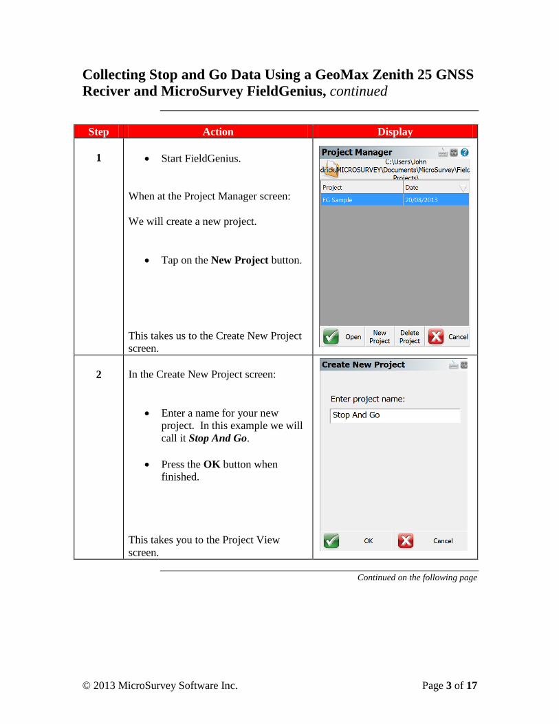
1
Start FieldGenius.
When at the Project Manager screen:
We will create a new project.
Tap on the New Project button.
This takes us to the Create New Project
screen.
2
In the Create New Project screen:
Enter a name for your new
project. In this example we will
call it Stop And Go.
Press the OK button when
finished.
This takes you to the Project View
screen.
Continued on the following page
© 2013 MicroSurvey Software Inc. Page 4 of 17
Collecting Stop and Go Data Using a GeoMax Zenith 25 GNSS
Reciver and MicroSurvey FieldGenius, continued
Step Action Display
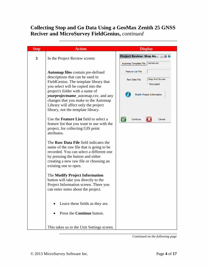
3
In the Project Review screen:
Automap files contain pre-defined
descriptions that can be used in
FieldGenius. The template library that
you select will be copied into the
project's folder with a name of
yourprojectname_automap.csv, and any
changes that you make to the Automap
Library will affect only the project
library, not the template library.
Use the Feature List field to select a
feature list that you want to use with the
project, for collecting GIS point
attributes.
The Raw Data File field indicates the
name of the raw file that is going to be
recorded. You can select a different one
by pressing the button and either
creating a new raw file or choosing an
existing one to open.
The Modify Project Information
button will take you directly to the
Project Information screen. There you
can enter notes about the project.
Leave these fields as they are.
Press the Continue button.
This takes us to the Unit Settings screen.
Continued on the following page
© 2013 MicroSurvey Software Inc. Page 5 of 17
Collecting Stop and Go Data Using a GeoMax Zenith 25 GNSS
Reciver and MicroSurvey FieldGenius, continued
Step Action Display
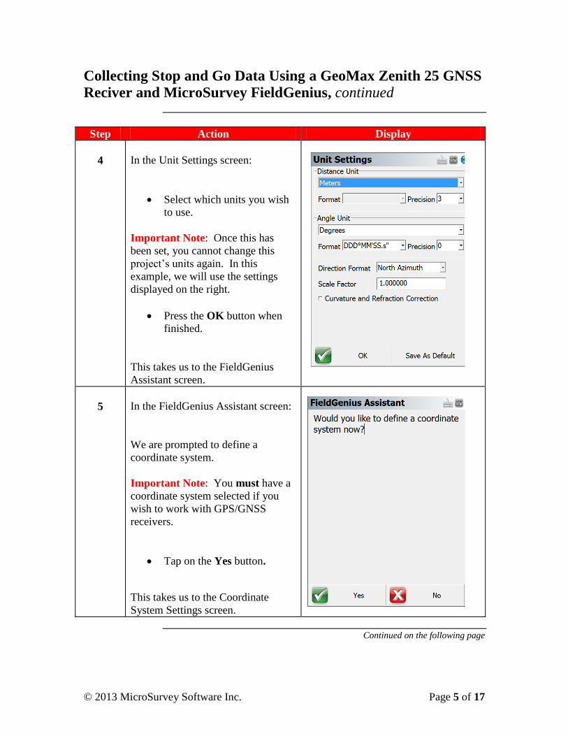
4
In the Unit Settings screen:
Select which units you wish
to use.
Important Note: Once this has
been set, you cannot change this
project’s units again. In this
example, we will use the settings
displayed on the right.
Press the OK button when
finished.
This takes us to the FieldGenius
Assistant screen.
5
In the FieldGenius Assistant screen:
We are prompted to define a
coordinate system.
Important Note: You must have a
coordinate system selected if you
wish to work with GPS/GNSS
receivers.
Tap on the Yes button.
This takes us to the Coordinate
System Settings screen.
Continued on the following page
© 2013 MicroSurvey Software Inc. Page 6 of 17
Collecting Stop and Go Data Using a GeoMax Zenith 25 GNSS
Reciver and MicroSurvey FieldGenius, continued
Step Action Display
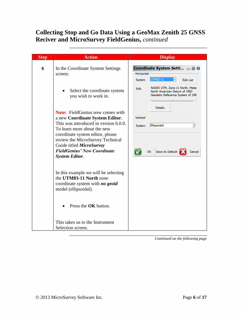
6
In the Coordinate System Settings
screen:
Select the coordinate system
you wish to work in.
Note: FieldGenius now comes with
a new Coordinate System Editor.
This was introduced in version 6.0.0.
To learn more about the new
coordinate system editor, please
review the MicroSurvey Technical
Guide titled MicroSurvey
FieldGenius’ New Coordinate
System Editor.
In this example we will be selecting
the UTM83-11 North zone
coordinate system with no geoid
model (ellipsoidal).
Press the OK button.
This takes us to the Instrument
Selection screen.
Continued on the following page
© 2013 MicroSurvey Software Inc. Page 7 of 17
Collecting Stop and Go Data Using a GeoMax Zenith 25 GNSS
Reciver and MicroSurvey FieldGenius, continued
Step Action Display
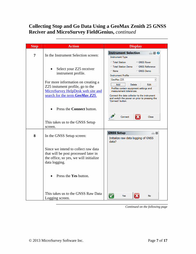
7
In the Instrument Selection screen:
Select your Z25 receiver
instrument profile.
For more information on creating a
Z25 instument profile, go to the
MicroSurvey HelpDesk web site and
search for the term GeoMax Z25.
Press the Connect button.
This takes us to the GNSS Setup
screen.
8
In the GNSS Setup screen:
Since we intend to collect raw data
that will be post processed later in
the office, so yes, we will initialize
data logging.
Press the Yes button.
This takes us to the GNSS Raw Data
Logging screen.
Continued on the following page
© 2013 MicroSurvey Software Inc. Page 8 of 17
Collecting Stop and Go Data Using a GeoMax Zenith 25 GNSS
Reciver and MicroSurvey FieldGenius, continued
Step Action Display
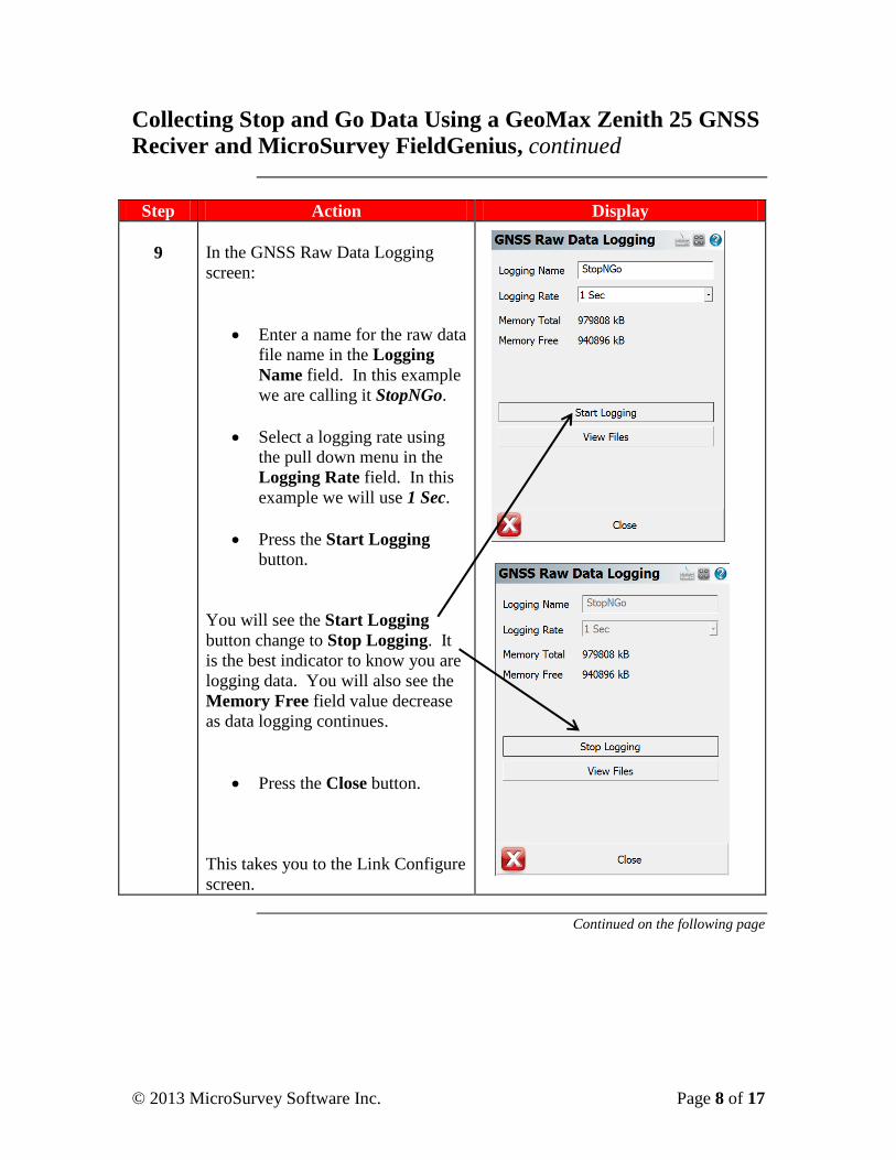
9
In the GNSS Raw Data Logging
screen:
Enter a name for the raw data
file name in the Logging
Name field. In this example
we are calling it StopNGo.
Select a logging rate using
the pull down menu in the
Logging Rate field. In this
example we will use 1 Sec.
Press the Start Logging
button.
You will see the Start Logging
button change to Stop Logging. It
is the best indicator to know you are
logging data. You will also see the
Memory Free field value decrease
as data logging continues.
Press the Close button.
This takes you to the Link Configure
screen.
Continued on the following page
© 2013 MicroSurvey Software Inc. Page 9 of 17
Collecting Stop and Go Data Using a GeoMax Zenith 25 GNSS
Reciver and MicroSurvey FieldGenius, continued
Step Action Display
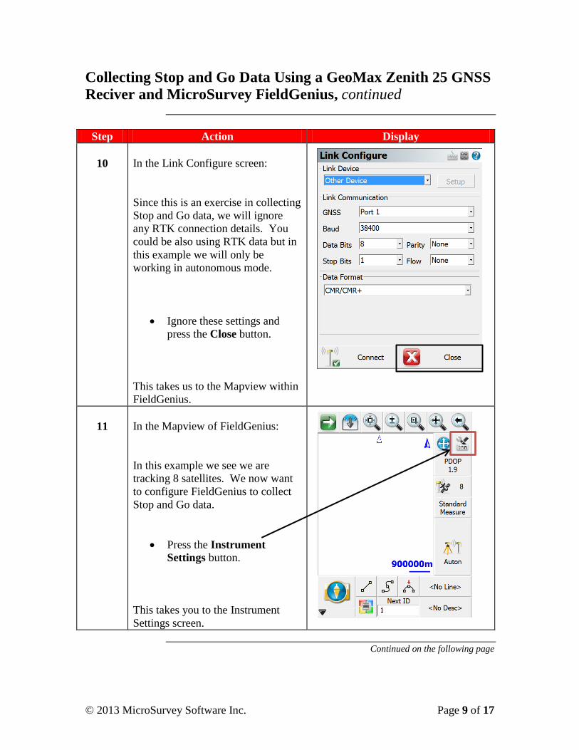
10
In the Link Configure screen:
Since this is an exercise in collecting
Stop and Go data, we will ignore
any RTK connection details. You
could be also using RTK data but in
this example we will only be
working in autonomous mode.
Ignore these settings and
press the Close button.
This takes us to the Mapview within
FieldGenius.
11
In the Mapview of FieldGenius:
In this example we see we are
tracking 8 satellites. We now want
to configure FieldGenius to collect
Stop and Go data.
Press the Instrument
Settings button.
This takes you to the Instrument
Settings screen.
Continued on the following page
© 2013 MicroSurvey Software Inc. Page 10 of 17
Collecting Stop and Go Data Using a GeoMax Zenith 25 GNSS
Reciver and MicroSurvey FieldGenius, continued
Step Action Display
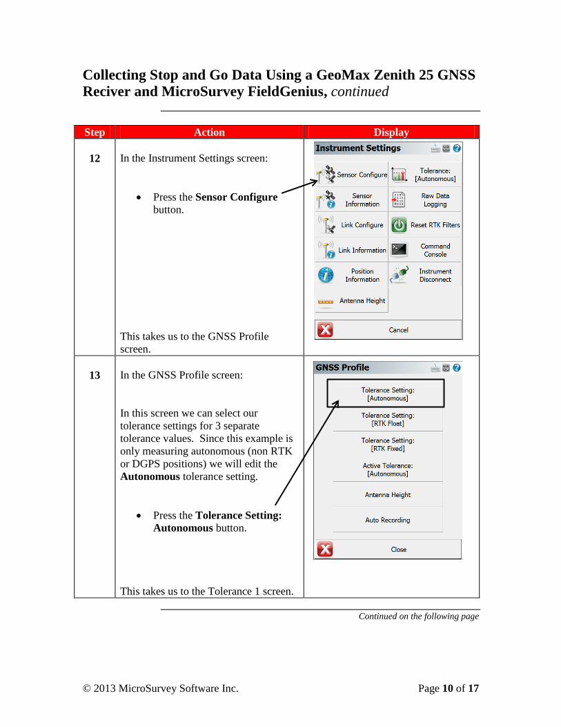
12
In the Instrument Settings screen:
Press the Sensor Configure
button.
This takes us to the GNSS Profile
screen.
13
In the GNSS Profile screen:
In this screen we can select our
tolerance settings for 3 separate
tolerance values. Since this example is
only measuring autonomous (non RTK
or DGPS positions) we will edit the
Autonomous tolerance setting.
Press the Tolerance Setting:
Autonomous button.
This takes us to the Tolerance 1 screen.
Continued on the following page
© 2013 MicroSurvey Software Inc. Page 11 of 17
Collecting Stop and Go Data Using a GeoMax Zenith 25 GNSS
Reciver and MicroSurvey FieldGenius, continued
Step Action Display
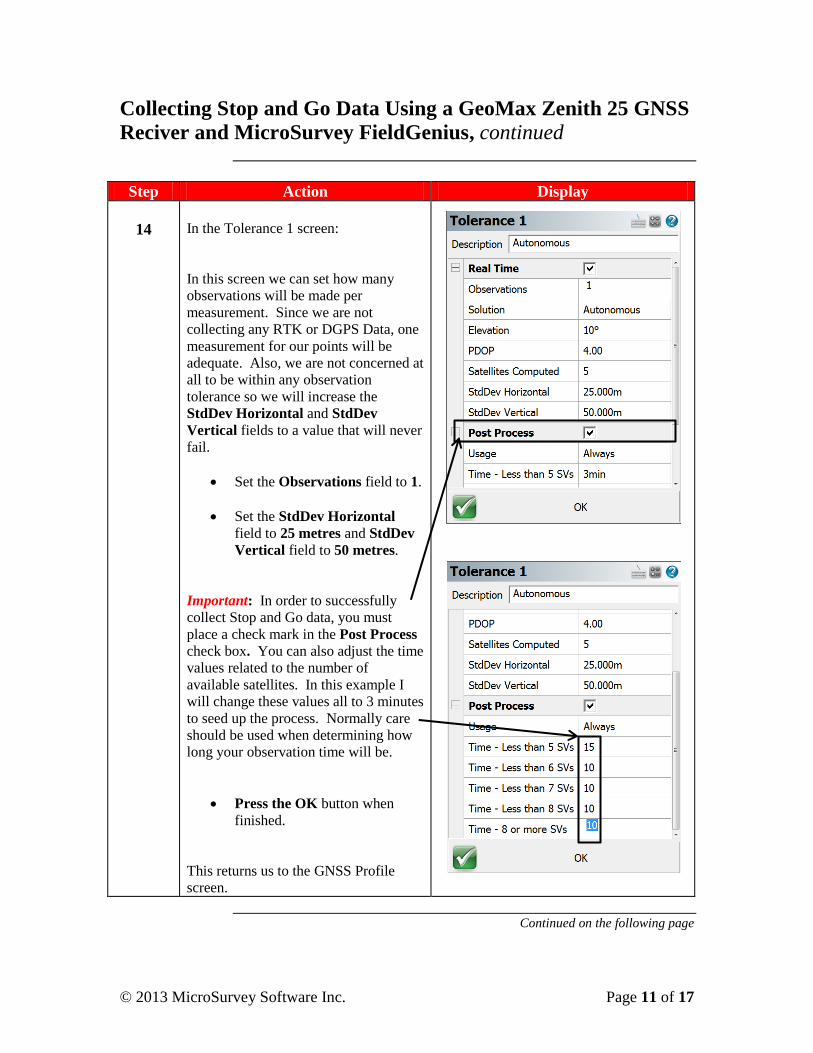
14
In the Tolerance 1 screen:
In this screen we can set how many
observations will be made per
measurement. Since we are not
collecting any RTK or DGPS Data, one
measurement for our points will be
adequate. Also, we are not concerned at
all to be within any observation
tolerance so we will increase the
StdDev Horizontal and StdDev
Vertical fields to a value that will never
fail.
Set the Observations field to 1.
Set the StdDev Horizontal
field to 25 metres and StdDev
Vertical field to 50 metres.
Important: In order to successfully
collect Stop and Go data, you must
place a check mark in the Post Process
check box. You can also adjust the time
values related to the number of
available satellites. In this example I
will change these values all to 3 minutes
to seed up the process. Normally care
should be used when determining how
long your observation time will be.
Press the OK button when
finished.
This returns us to the GNSS Profile
screen.
Continued on the following page
© 2013 MicroSurvey Software Inc. Page 12 of 17
Collecting Stop and Go Data Using a GeoMax Zenith 25 GNSS
Reciver and MicroSurvey FieldGenius, continued
Step Action Display
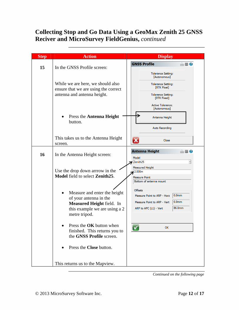
15
In the GNSS Profile screen:
While we are here, we should also
ensure that we are using the correct
antenna and antenna height.
Press the Antenna Height
button.
This takes us to the Antenna Height
screen.
16
In the Antenna Height screen:
Use the drop down arrrow in the
Model field to select Zenith25.
Measure and enter the height
of your antenna in the
Measured Height field. In
this example we are using a 2
metre tripod.
Press the OK button when
finished. This returns you to
the GNSS Profile screen.
Press the Close button.
This returns us to the Mapview.
Continued on the following page
© 2013 MicroSurvey Software Inc. Page 13 of 17
Collecting Stop and Go Data Using a GeoMax Zenith 25 GNSS
Reciver and MicroSurvey FieldGenius, continued
So Far We have configured FieldGenius to record Stop and Go data while
measuring points in real-time mode even though we have no real-time
corrections coming in (that is, we are in autonomous mode).
We then set the correct antenna type and entered a height of antenna.
We are now ready to record data. Set up your receiver over the point
you wish to measure. Since the receiver’s antenna should not move
during this occupation, a tripod or bi-pod should be used to steady the
antenna.
Step Action Display
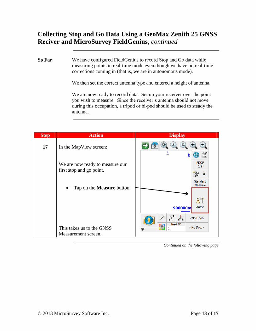
17
In the MapView screen:
We are now ready to measure our
first stop and go point.
Tap on the Measure button.
This takes us to the GNSS
Measurement screen.
Continued on the following page
© 2013 MicroSurvey Software Inc. Page 14 of 17
Collecting Stop and Go Data Using a GeoMax Zenith 25 GNSS
Reciver and MicroSurvey FieldGenius, continued
Step Action Display
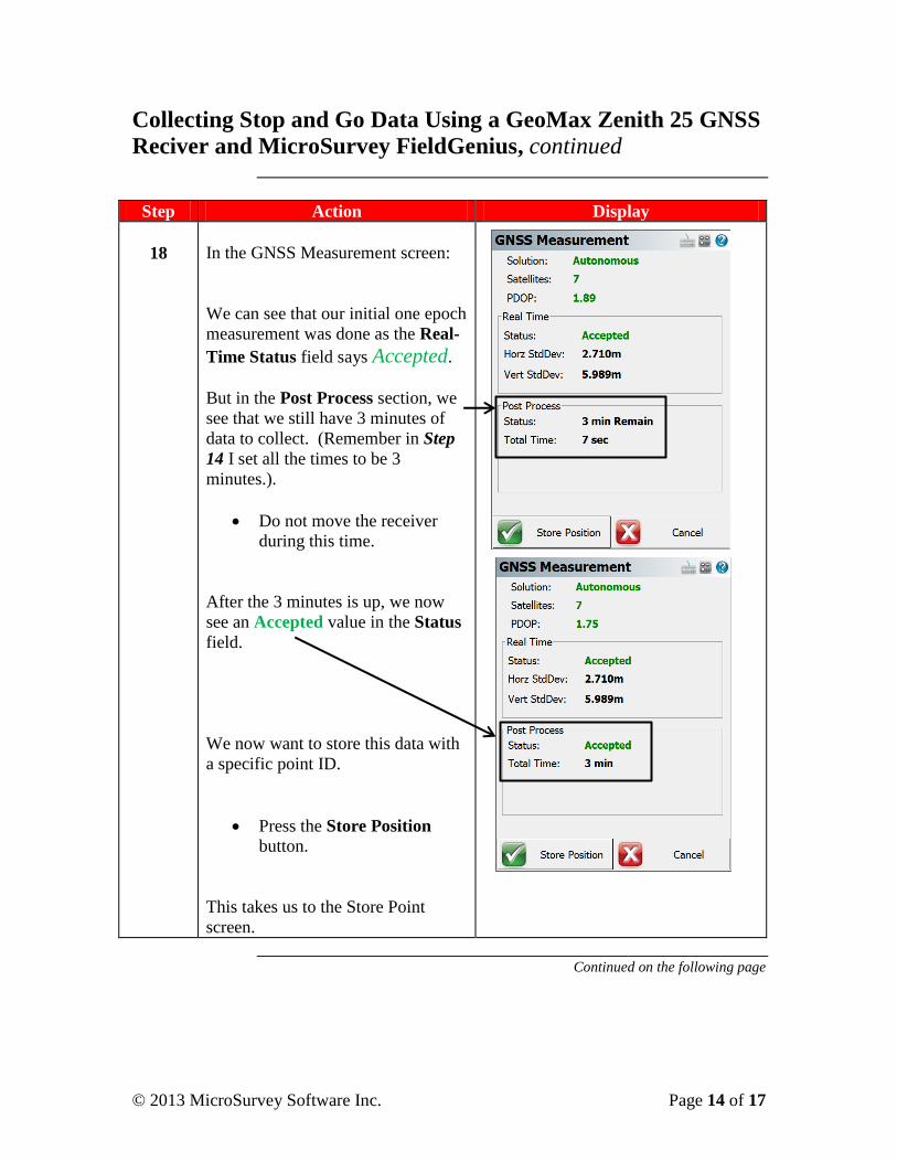
18
In the GNSS Measurement screen:
We can see that our initial one epoch
measurement was done as the Real-
Time Status field says Accepted.
But in the Post Process section, we
see that we still have 3 minutes of
data to collect. (Remember in Step
14 I set all the times to be 3
minutes.).
Do not move the receiver
during this time.
After the 3 minutes is up, we now
see an Accepted value in the Status
field.
We now want to store this data with
a specific point ID.
Press the Store Position
button.
This takes us to the Store Point
screen.
Continued on the following page
© 2013 MicroSurvey Software Inc. Page 15 of 17
Collecting Stop and Go Data Using a GeoMax Zenith 25 GNSS
Reciver and MicroSurvey FieldGenius, continued
Step Action Display
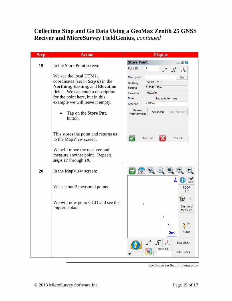
19
In the Store Point screen:
We see the local UTM11
coordinates (set in Step 6) in the
Northing, Easting, and Elevation
fields. We can enter a description
for the point here, but in this
example we will leave it empty.
Tap on the Store Pnt.
button.
This stores the point and returns us
to the MapView screen.
We will move the receiver and
measure another point. Repeats
steps 17 through 19.
20
In the MapView screen:
We see our 2 measured points.
We will now go to GGO and see the
imported data.
Continued on the following page
© 2013 MicroSurvey Software Inc. Page 16 of 17
Collecting Stop and Go Data Using a GeoMax Zenith 25 GNSS
Reciver and MicroSurvey FieldGenius, continued
GGO Remember: This guide assumes you know how to use GGO
(GeoMax Geo Office), and providing user guidance on this software
is beyond the purview of this training guide.
Step Action Display
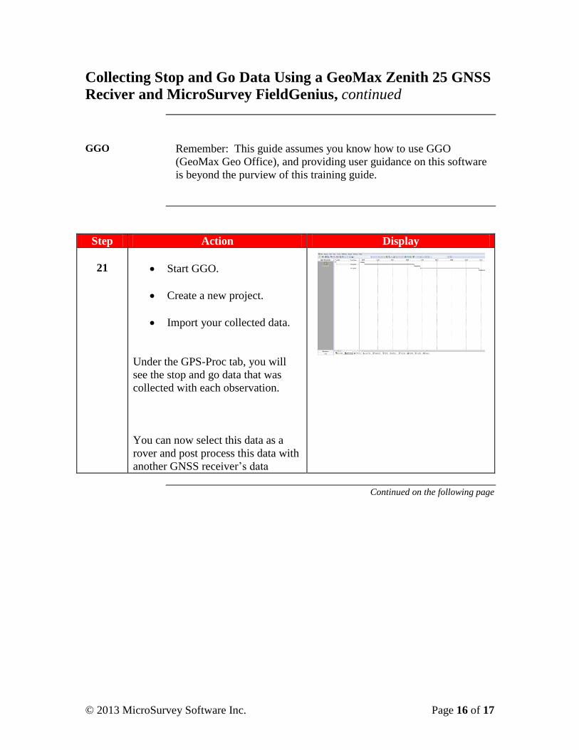
21
Start GGO.
Create a new project.
Import your collected data.
Under the GPS-Proc tab, you will
see the stop and go data that was
collected with each observation.
You can now select this data as a
rover and post process this data with
another GNSS receiver’s data
Continued on the following page
© 2013 MicroSurvey Software Inc. Page 17 of 17
Collecting Stop and Go Data Using a GeoMax Zenith 25 GNSS
Reciver and MicroSurvey FieldGenius, continued
Congratulations You have successfully configured FieldGenius to collect Stop and
Go data.
You then entered the correct antenna height and selected the correct
antenna model and were ready to start measuring.
You measured 2 points while collecting Stop and Go data.
You then imported the data and were ready to post process it against
other GNSS data.
Glossary GNSS – Global Positioning System
ISP – Internet Service Provider
PIN – Personal Identification Number
PUK – PIN Unlocked Key
GSM – Global System for Mobile Communications
CDMA – Code Division Multiple Access
ISP - Internet Service Provider
NTRIP – Networked Transport of RTCM via Internet Protocol
NTRIP Caster – an HTTP server that accepts request-messages on a
single port and then decides where there is streaming data to receive
or to send. The caster offers a list of mountpoints that is called a
source list or source table.
HTTP: Hypertext Transfer Protocol
SIM - Subscriber Identity Module
RTCM - Radio Technical Commision for Martitime
RTK – Real Time Kinematic