geology and stratigraphy of fluvio-deltaic deposits in the ... · significant remaining reserves in...
TRANSCRIPT
ABSTRACT
Significant remaining reserves in Prudhoe Bayfield are confined within deltaic rocks at the baseof the Triassic Ivishak sandstone. The initial strati-graphic characterization of the Prudhoe Bay reser-voir was lithostratigraphically based, and it depict-ed this basal reservoir interval as tabular zonesbetween marine shale and overlying coarse-grained, fluvial sandstones. A reassessment of thisinterval based on cores and genetic-stratigraphiccorrelations depicts en echelon, offlapping, fluvial-ly dominated deltaic wedges.
Reservoir-quality rocks occur in distributarymouth bar, distributary channel, and fluvial faciesassociations. A paleogeographic reconstruction ofone delta lobe includes an alluvial plain crossed bychannels of possibly braided or low-sinuosityrivers. This alluvial plain graded into a delta plaincut by distributary channels that fed distributarymouth bars on a broad delta front. River domi-nance is inferred from the abundance of unidirec-tional current structures, normally graded beds,soft-sediment deformation, and general absence ofwave-formed, tidal, and biogenic structures.Slumping and growth faulting locally replaced
1588 AAPG Bulletin, V. 83, No. 10 (October 1999), P. 1588–1623.
©Copyright 1999. The American Association of Petroleum Geologists. Allrights reserved.
1Manuscript received March 17, 1998; revised manuscript receivedFebruary 5, 1999; final acceptance March 3, 1999.
2ARCO 2300 West Plano Parkway, Plano, Texas 75075-8499; e-mail:[email protected]
3ARCO El-Djazair, 2300 West Plano Parkway, Plano, Texas 75075-8499.4ARCO Alaska, Inc. 700 G Street, Anchorage, Alaska 99510-0360.5Exxon Azerbaijan Operating Company, Landmark, Suite 300, 96 Nizami
Street, Baku, 370000, Azerbaijan Republic.We thank the Prudhoe Bay Working Interest Owners for their support and
permission to publish this paper. Many individuals aided our work by sharingtheir experience and knowledge. Among those to whom we are especiallygrateful are P. A. Barker, D. Bodnar, L. Corwin, M. Deacon, E. H. Gustason,W. D. Masterson, J. H. McGowen, and M. T. Richards. Jack Fitzpatrick,Katherine Hale, Ken Nelson, and Darrell Irving provided graphic support. D. Przyowjski and M. Stanford cheerfully helped in the core lab. Earlyversions of this manuscript were reviewed by J. L. Hand, M. C. Kremer, andP. L. McGuire. AAPG reviewers J. Michael Casey, N. Hurley, Keith W. Shanley, R. W. Tillman, and K. M. Wolgemuth are thanked for theirreviews and suggested improvements.
Geology and Stratigraphy of Fluvio-Deltaic Deposits inthe Ivishak Formation: Applications for Development ofPrudhoe Bay Field, Alaska1
Robert S. Tye,2 Janok P. Bhattacharya,2 James A. Lorsong,3 Scott T. Sindelar,4
Douglas G. Knock,4 David D. Puls,5 and Richard A. Levinson4
coarsening-upward deltaic successions with sharp-based, overthickened mouth bar and distributarychannel deposits.
Mudstones deposited following delta-lobe aban-donment form laterally extensive f low barriersbetween lobes. Compartmentalization is most pro-nounced distally, where deltaic sandstones areoverlain by and pass laterally into marine shale.Proximally, fluvial and deltaic sandstones are juxta-posed across erosional contacts, improving reser-voir continuity.
This stratigraphic interpretation is corroboratedby production and surveillance data plus an interfer-ence test. Locally, stratigraphy and poor waterfloodperformance reflect completions in diachronoussandstones that originated in separate deltaic lobes.Previously, poor well performances were attributed tosandstone pinch-outs. In some cases, production canbe enhanced with recompletions rather than infilldrilling. Nonconventional wells planned and complet-ed with the benefit of detailed facies-association correlations currently are recovering millions of bar-rels of previously bypassed oil.
INTRODUCTION
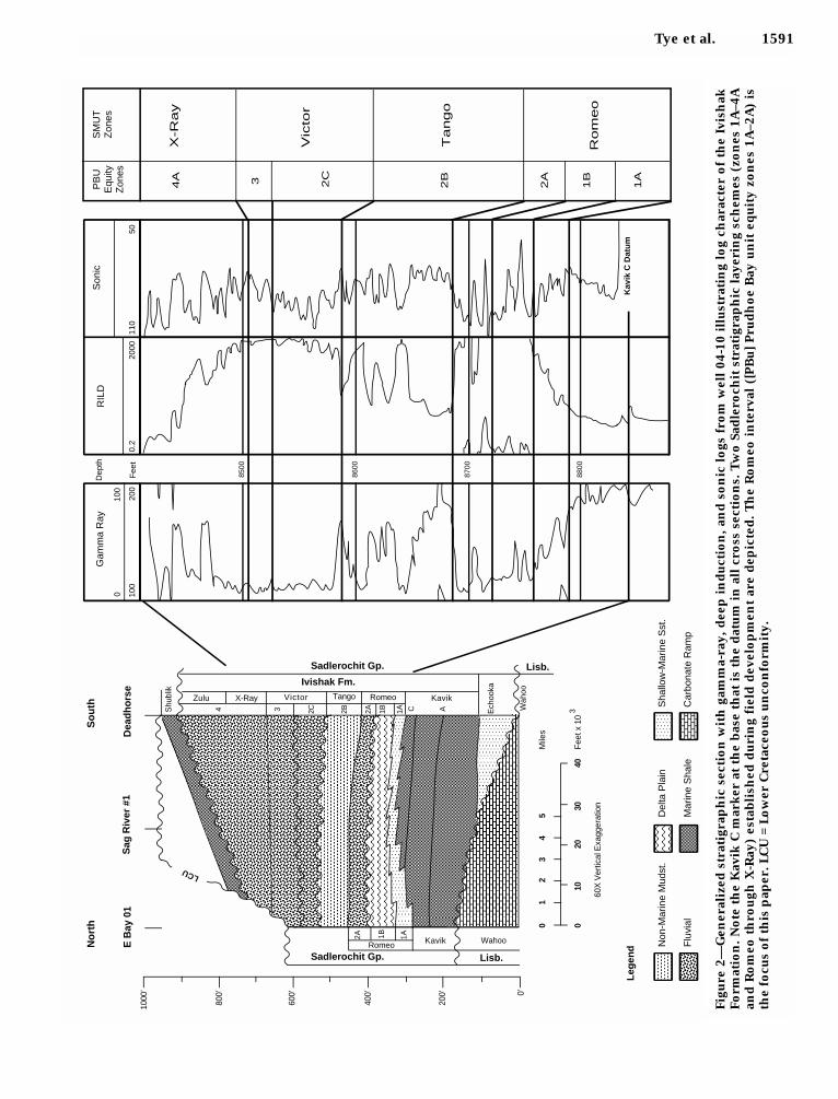
As with all oil fields, development practices atPrudhoe Bay field on Alaska’s North Slope (Figure1) have evolved as the field has matured. As a con-sequence, descriptions of the reservoir made dur-ing early field production, when the most perme-able zones were perforated, became unsatisfactoryfor matching well performance as lower permeabil-ity rocks were perforated (Szabo and Meyers,1993). With the onset of declining production inthe 1980s, it was determined that a significant por-tion of Prudhoe’s remaining reserves reside withinfluvio-deltaic sandstones at the base of the reser-voir. These rocks are operationally referred to asthe Romeo interval (Figure 2). Romeo oil had beennotoriously more difficult to produce than oil inthe overlying nonmarine strata possessing higher

Tye et al. 1589
Figure 1—The Alaskan North Slope and location of Prudhoe Bay field between the National Petroleum Reserve(NPRA) and the Arctic National Wildlife Refuge (ANWR). ARCO operates the eastern operating area (EOA). Loca-tions of cross sections (Figures 5–7) and cored wells are shown. Boxes highlight locations of Figures 4 and 8,respectively. PBU = Prudhoe Bay unit.

porosities and permeabilities; moreover, limitedgeologic information (core descriptions), erraticproduction histories, and poor producibility exac-erbated the Romeo’s reputation as comprisinglithologically heterogeneous and discontinuousstrata.
In light of declining production, the present reser-voir engineering focus at Prudhoe Bay is on evaluat-ing reservoir sweep efficiency and the impact andeconomics of various recovery mechanisms (e.g.,gravity drainage, waterflood, estimated oil recov-ery). It has been proposed that immediate produc-tion increases can be attained and maintainedthrough the selective drilling of Romeo infill wellson 80 or 40 ac (32 or 16 ha) spacings; however,reservoir sweep efficiency in the Romeo at presentwell spacings (160 and 80 ac; 64 and 32 ha) is equiv-ocal. Additionally, controversy has arisen concerningthe most efficient recovery methods to be used.
Following equity agreements, previously unavail-able cores were released for geologic analyses.These additional data helped revise existing reser-voir descriptions; therefore, ARCO, BP, and Exxonestablished teams of geologists, geophysicists, andreservoir engineers to describe the Romeo intervaland to conduct flow simulations for various devel-opment scenarios. This interdisciplinary group pro-vided a full-field geologic, geophysical, and petro-physical characterization of the Romeo interval(Bellamy, 1993; Richards et al., 1994). Additionally,both prior to, and simultaneously with, the multi-company program, ARCO geoscientists and engi-neers initiated smaller scale, two- and three-dimensional reservoir description projects toaddress specific development issues within theeastern operating area (EOA) (Figure 1) (Lorsong etal., 1994; Tye et al., 1994).
Prudhoe Bay Field
Prudhoe Bay field lies on the Alaska coastal plain264 mi (425 km) north of the Arctic Circle betweenNaval Petroleum Reserve (NPRA) No. 4 and theArctic National Wildlife Refuge (ANWR) (Figure 1).Production from Permian–Triassic sandstones andconglomerates of the Sadlerochit Group (Figure 2)was 1.5 MMSTB/day (million stock tank bbl/day) atfield start-up in 1977 (Szabo and Meyers, 1993).The Sadlerochit Group unconformably overlies theLisburne Group and comprises the EchookaFormation, the Kavik shale, and the IvishakFormation, the main reservoir interval at PrudhoeBay field. Where it crops out in ANWR, the Ivishakis divided into the Kavik, Ledge Sandstone, andFire Creek members (Crowder, 1990); however,these stratigraphic divisions are not carried intothe subsurface.
Gentle southerly structural dip combined with anorth-bounding fault, an unconformity truncationto the east (LCU, Figure 2), and overlying shalescreate the trap and seal. In-place reserve estimateshave risen as development has progressed. Morg-ridge and Smith (1972) reported reserves of 9.6 bil-lion bbl of oil and 26 tcf (trillion cubic feet) of gas. By1990, in-place reserve estimates were updated to22 billion bbl of oil and 47 tcf of gas (Atkinson etal., 1990). Szabo and Meyers (1993) argued thatdiligent reservoir management practices imple-mented since field start-up account for a 25%increase in recoverable reserves.
Previous Ivishak Interpretations
A deltaic origin has been embraced for basalIvishak (Romeo) strata since field discovery(Detterman, 1970; Morgridge and Smith, 1972;Eckelmann et al., 1975; Jones and Spears, 1976;Wadman et al., 1979; Jamison et al., 1980; Melvinand Knight, 1984; Lawton et al., 1987; McMillenand Colvin, 1987; Atkinson et al., 1988, 1990; Begget al., 1992). This interpretation is founded primari-ly on the Ivishak’s apparent conformable stratigra-phy in which basal marine shales grade upwardthrough shallow-marine and finally into fluvial stra-ta. Fluvial strata have been described as braided-river deposits on a coastal plain (Eckelmann et al.,1975; Jones and Spears, 1976; Wadman et al., 1979;Melvin and Knight, 1984; Lawton et al., 1987;Atkinson et al., 1990) or on a large alluvial fan(McGowen and Bloch, 1985; McGowen et al.,1987). More specifically, Romeo deltaic depositshave been interpreted as those of fan deltas or mul-tiple coastal deltas fed by several coeval fluvial sys-tems. Lawton et al. (1987) interpreted the prepon-derance of distributary channel and mouth bardeposits as indicative of river-dominated deltadeposition; Begg et al. (1992) reached a similarconclusion.
Initially, the Ivishak Formation in Prudhoe Bayfield was subdivided into four equity zones charac-terized by differing log responses (Figure 2)(Eckelmann et al., 1975; Jones and Spears, 1976;Atkinson et al., 1988, 1990). Log response is strong-ly tied to lithology (Atkinson et al., 1988, 1990;Melvin and Knight, 1984); thus, well-to-well corre-lation of the four zones imposes a lithostratigraphicframework on the Ivishak Formation. These zonesconstituted operational subdivisions for reservoirengineering and geologic analyses (Wadman et al.,1979; Melvin and Knight, 1984).
Atkinson et al. (1988, 1990) recognized thatreservoir performance was strongly influenced byshales. These workers separated the Ivishak intothree sandstone to conglomerate units (Romeo,
1590 Fluvio-Deltaic Deposits in the Ivishak Formation
Tye et al. 1591
Fig
ure
2—
Gen
eral
ized
str
atig
rap
hic
sec
tio
n w
ith
gam
ma-
ray,
dee
p i
nd
uct
ion
, an
d s
on
ic l
ogs
fro
m w
ell
04-1
0 i
llu
stra
tin
g lo
g ch
arac
ter
of
the
Ivis
hak
Fo
rmat
ion
. N
ote
th
e K
avik
C m
ark
er a
t th
e b
ase
that
is
the
dat
um
in
all
cro
ss s
ecti
on
s. T
wo
Sad
lero
chit
str
atig
rap
hic
lay
erin
g sc
hem
es (
zon
es 1
A–4
Aan
d R
om
eo t
hro
ugh
X-R
ay)
esta
bli
shed
du
rin
g fi
eld
dev
elo
pm
ent
are
dep
icte
d.
Th
e R
om
eo i
nte
rval
([P
Bu
] P
rud
ho
e B
ay u
nit
eq
uit
y z
on
es 1
A–2
A)
isth
e fo
cus
of
this
pap
er. L
CU
= L
ow
er C
reta
ceo
us
un
con
form
ity.
X-R
ay
Vic
tor
Tango
Rom
eo
1A
1B
2A
2B
2C34A
001
23
3
45
Mile
s
40F
eet x
10
3020
10
60X
Ver
tical
Exa
gger
atio
n
1000
’
800’
600’
400’
200’ 0’
E B
ay 0
1D
eadh
orse
Ech
ooka
Wah
oo
Shu
blik
C A1A1B2A2B2C34
1A1B2A
No
rth
So
uth
Zulu X-Ray Victor Tango KavikRomeo
Ivishak Fm.
Sadlerochit Gp. Lisb.
KavikRomeo Wahoo
Lisb.Sadlerochit Gp.
Sag
Riv
er #
1
LCU
Gam
ma
Ray
010
0
100
200
Dep
th
Fee
t
RIL
D
0.2
2000
Son
ic
110
50
8500
8600
8700
8800
Kav
ik C
Dat
um
Leg
end N
on-M
arin
e M
udst
.
Flu
vial
Del
ta P
lain
Mar
ine
Sha
le
Sha
llow
-Mar
ine
Sst
.
Car
bona
te R
amp
PB
UE
quity
Zon
es
SM
UT
Zon
es
Victor, and Zulu, Figure 2). These stratigraphic divi-sions were termed “flow units,” emphasizing theirsignificance as hydraulic layers. Atkinson et al.(1988) divided the Romeo flow unit into two sub-units on the basis of better reservoir-quality rock atthe top and lesser quality rock below. These sub-units correspond to different depositional facies.The lowermost unit (1A) consists primarily ofprodelta and distal-delta front, whereas the upperunit (1B) contains distributary mouth bar and dis-tributary channel deposits. Cross sections impliedlateral persistence of subunits, prompting their treat-ment as tabular layers of relatively uniform thickness(Melvin and Knight, 1984; Atkinson et al., 1990).
Difficulties in field development, possiblyattributable to reservoir stratigraphy, became apparent
as basal Ivishak sandstones were targeted, thusspurring additional geological studies (Begg et al.,1992; Bellamy, 1993; Bhattacharya et al., 1994;Lorsong et al., 1994; Richards et al., 1994; Tye etal., 1994; Puls et al., 1995). These studies benefitedfrom access to a large number of previouslyunavailable (preserved) cores. Newly acquiredsedimentologic insights and genetic stratigraph-ic concepts warrant new interpretations ofRomeo stratal geometries, specifically the rela-tionship of lower Romeo clinoform strata withKavik shales. This interpretation contrasts withthe layer-cake stratigraphy previously depictedand requires a more complex interpretation off low units. The focus of this paper is how thisinterpretation influences the density, placement,
1592 Fluvio-Deltaic Deposits in the Ivishak Formation
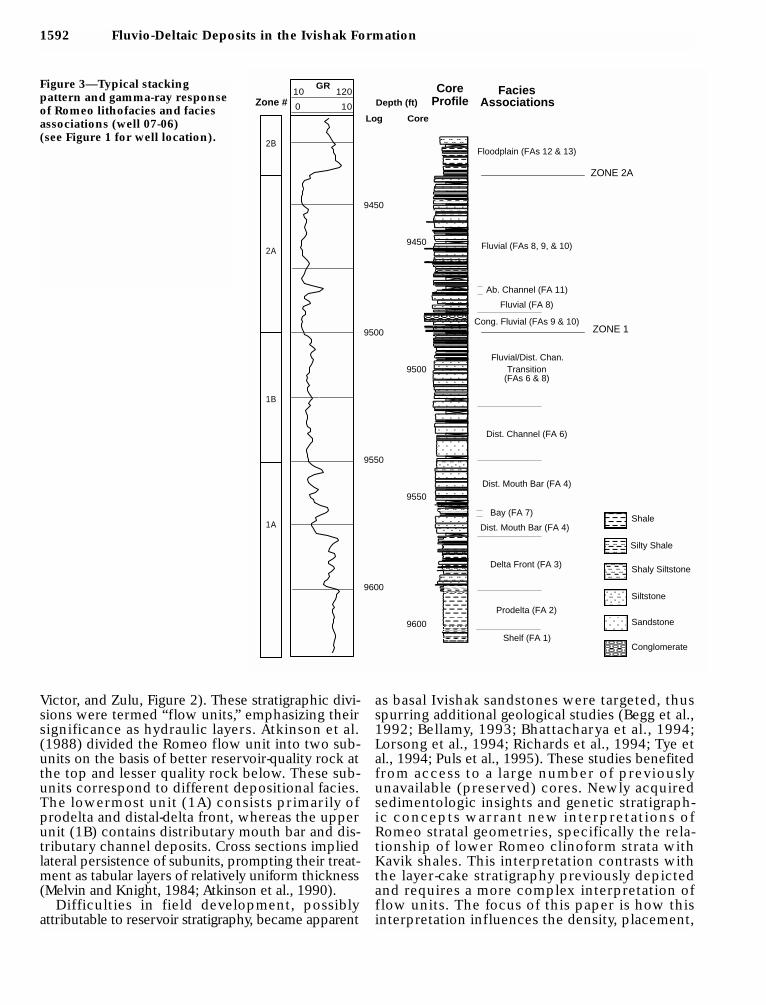
Figure 3—Typical stacking pattern and gamma-ray responseof Romeo lithofacies and faciesassociations (well 07-06) (see Figure 1 for well location).
Conglomerate
Silty Shale
Shaly Siltstone
Siltstone
Sandstone
Shale
Dist. Channel (FA 6)
Bay (FA 7)
Dist. Mouth Bar (FA 4)
Delta Front (FA 3)
Prodelta (FA 2)
Floodplain (FAs 12 & 13)
Fluvial (FAs 8, 9, & 10)
Cong. Fluvial (FAs 9 & 10)
Fluvial (FA 8)
Ab. Channel (FA 11)
Fluvial/Dist. Chan.
Dist. Mouth Bar (FA 4)
Transition
Shelf (FA 1)
(FAs 6 & 8)
ZONE 2A
ZONE 1
AssociationsFaciesCore
Profile
9450
9500
9550
9600
Core
9450
9500
9550
9600
Log
1A
1B
2A
GR10 120
0 10Zone #
2B
Depth (ft)

and type of wells drilled, as well as completionpractices in the Romeo. Accompanying work(Lorsong et al., 1994) focused on methods toquantify this geologic description for reservoirsimulation.
Objectives and Methods
The main objective of this study was to use coredescriptions, facies interpretations, and stratigraph-ic correlations to geologically characterize produc-tive and nonproductive intervals of the Romeowithin selected regions of the EOA. Approximately5000 ft (1525 m) of core were described from 27wells (Figure 1). Descriptions focused on recogniz-ing sedimentary facies and emphasized interpretingsedimentary processes. Through core analyses, reg-ularly occurring facies associations (see theAppendix) and vertical relationships were recog-nized (Figure 3). Facies associations were used asthe basic correlation units of the Romeo interval,they were mapped within specific stratigraphicintervals, and they constitute the building blocksfor reservoir simulation models.
Seventeen cross sections incorporating approxi-mately 250 wells (Figure 1) were constructedacross the EOA. Sections were datumed within theunderlying Kavik shale. Well data (log and core)were correlated following the concepts outlined inFisher et al. (1969), Brown (1969), Frazier (1974),Galloway (1989), and van Wagoner et al. (1990).Following the examples of these workers, ourstudy emphasizes identifying and correlating time-equivalent, genetically linked sedimentary facies ininterpreting resultant depositional systems and sys-tems tracts. Well performance, limited pressuredata, and facies relationships (Reading, 1986;Bhattacharya and Walker, 1992; Posamentier et al.,1993) guided geologic correlation.
Choosing a Datum
Recognizing a stratigraphic datum is perhaps themost important decision made in the early stages ofa subsurface appraisal project. Previous work atPrudhoe Bay suggested that FA 1 (facies association1) sandstones could be calibrated to easily identifi-able and areally extensive wireline log markers.Thus, with corroborating core data, a Kavik (FA 1)marine-flooding surface, assumed to have been flatduring Ivishak deposition, was picked as the datum(Figure 2). A condensed section above the floodingsurface (Loutit et al., 1988; Bhattacharya andPosamentier, 1994) is manifested as a highlyradioactive gamma-ray response. Where this mark-er was not penetrated, stratigraphically higher
picks corresponding to shaly facies associationswere used to approximate a well’s stratigraphicposition.
FACIES ASSOCIATIONS AND DEPOSITIONALINTERPRETATIONS
Core data provide the foundation on which ourgeologic observations, interpretations, and conclu-sions are based. Distinguishing sedimentologic andstratigraphic characteristics of each sedimentaryfacies and facies association, as well as the contactsseparating them, are described and interpreted inthe Appendix and summarized in Table 1.
Our study follows previously presented faciesschemes for basal Ivishak strata (Melvin andKnight, 1984; Lawton et al., 1987; Atkinson et al.,1988; Begg et al., 1992); however, newly availablecore data enabled us to add sedimentologic andstratigraphic detail. With refined geologic insightsgained from the core descriptions, we interpreted13 facies associations representing 11 depositionalsettings (shelf, prodelta, delta front, distributarymouth bar, distributary channel, shoreface, bay, flu-vial channel, abandoned channel, crevasse splay,and flood plain) (Table 1, Appendix). These deposi-tional facies associations were correlated andmapped within time-stratigraphic boundaries.
NATURE OF THE ROMEO DELTAS
Although most previous workers agree about adeltaic origin for Romeo sandstones (Morgridgeand Smith 1972; Eckelmann et al., 1975; Wadman etal., 1979; Lawton et al., 1987; Atkinson et al., 1990),our interpretation of basal Ivishak deposits differssomewhat from an alluvial fan-delta system (Melvinand Knight, 1984) or the braided-river/delta-frontsetting of Atkinson et al. (1990). Interpretationaldifferences focus primarily on the size of the fluvialfeeder system, slope and scale of the deltaic plain,and dominant river-mouth processes controllingsediment distribution. Instead of interpreting theIvishak as a conformable delta front to braided-stream sequence (Atkinson et al., 1988, 1990), weenvision it as a marine to deltaic and fluvial succes-sion punctuated by numerous tectonically inducedunconformities. Episodic uplift of the source area,not interfingering lithofacies, is deemed responsi-ble for the grain size variability and changes in flu-vial style noted in the nonmarine strata overlyingthe Romeo.
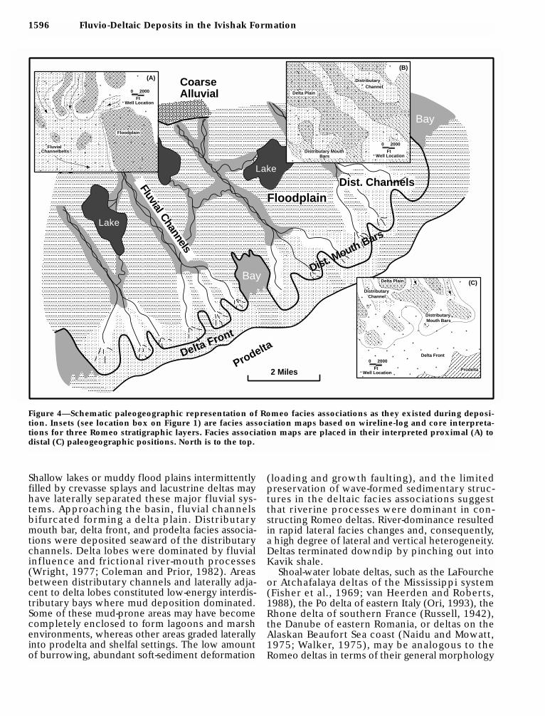
Our reconstruction of the Romeo interval de-picts southeastward-oriented low-gradient and fine-grained fluvial systems that extended 100 km (62mi) or more from the source area (Figure 4).
Tye et al. 1593

1594 Fluvio-Deltaic Deposits in the Ivishak Formation
Table 1. Summary of Sedimentary Characteristics*
Facies Physical BiogenicAssoc. Lithology Texture Structure Structure
FA 1 Mudstone Claystone to Symmetrical ripple lamination; Numerous burrow tracesand sandstone very fine grained hummocky cross-stratification including Teichichnus,
Rosselia, Planolites, andZoophycos
FA 2 Heterolithic mudstone, Claystone to Load casts, microfaults, and Rare burrows includingsiltstone (30%), and very fine grained fluid-escape pipes; Teichichnus, Planolites,sandstone (5%) normal grading; symmetric Thalassinoides, pectin
and asymmetric ripple casts; maceratedcross-lamination organic debris
FA 3 Heterolithic claystone Claystone to Normal grading, symmetric Macerated organic debris;and siltstone (60%), very fine grained and asymmetric ripple rare burrow tracesand very fine grained cross-lamination; raresandstone (40%); hummocky cross-stratification;trace of fine- to ball-and-pillow, convoluted, andmedium-grained overturned bedding, faulting,sandstone and dewatering features
FA 4 Sandstone (90%) with Very fine (50%), fine Flat lamination; low-angle Sparsely burrowed;minor siltstone grained (30%), and cross-beds; truncation surfaces; macerated organicand mudstone (10%) medium grained symmetric, combined-flow, debris
(10%) and asymmetric-current ripplelamination; fluid-escape featuresand synsedimentary faults
FA 5 Sandstone Very fine to Normal grading; flat to low-angle Moderate burrow tracesfine grained laminae; symmetric and including
combined-flow ripple laminae; Macaronichus,rare asymmetric-ripple Palaeophycus,laminae; reactivation and scour Teichichnus, andsurfaces; hummocky Skolithos; maceratedcross-stratification organic debris
FA 6 Sandstone (95%); minor Medium (50%), Sharp based; trough and planar tabular Macerated organicchert pebbles, siltstone fine (30%) to very cross-bedding, parallel lamination and debrisand mudstone (5%) fine grained (15%) asymmetric-ripple lamination
FA 7 Heterolithic mudstone, Claystone to Symmetric- and asymmetric- Sparse burrowssiltstone (80%), and very fine grained ripple lamination; lenticular including Arenicolitesminor sandstone (20%) beds; loading and mud cracks
FA 8 Sandstone (97%); Medium (60%), fine Parallel lamination; planar Not observedchert granules and (30%) to very fine cross-bedding; asymmetric-pebbles (2%); minor grained (7%) ripple laminationmudstone (1%)
FA 9 Conglomerate, pebbly Coarse to Poorly stratified to Not observedsandstone, sandstone fine grained cross-bedded; normally graded;(99%); minor asymmetric-ripple laminationmudstone (1%)
FA 10 Conglomerate, sandy Coarse grained Poorly stratifiedconglomerate
FA 11 Heterolithic mudstone Claystone (55%), Asymmetric-ripple lamination; Not observed(55%) and very fine grained soft-sediment deformationsandstone (45%) (40%) and medium
to fine grained (5%)FA 12 Heterolithic mudstone Mudstone (20%), very Asymmetric- and symmetric- Rare Scoyenia
(20%) and fine grained (50%), ripple lamination; soft-sandstone (80%) fine grained (20%), sediment deformation
and coarse to mediumgrained (10%)
FA 13 Mudstone, siltstone, Claystone to very Irregular lamination; mud Rare Scoyenia; pedogenicrare sandstone fine grained cracks, slickensides features; root traces;
mottling
*Porosity and permeability values were provided by F. Paskvan (1993, personal communication) and represent mean values calculated from log and coredata.

Tye et al. 1595
Table 1. Continued.
Macroscopic Interpreted DepositionalDiagenetic Gamma-Ray Environment, Permeability, Comparison to PreviousFeatures Log Character and Porosity Depositional Interpretations
Framboidal and Upward coarsening; Marine shelf Not recognizednodular pyrite sharp-based sandstones
Nodular and Overall upward-coarsening Prodelta; Prodelta (Lawton et al.,bedded siderite sharp-based sandstones mean permeability = 3.4 md; 1987); prodelta and distal
mean porosity = 6.6% delta front (Atkinson et al.,1988)
Nodular and Coarsening upward Distal delta front; Distal delta front (Atkinsonbedded siderite to serrated mean permeability= 5.0 md; et al., 1988); distal bar
mean porosity = 10.4% (Lawton et al., 1987)
Siderite Overall upward coarsening; Proximal delta front; Distributary mouth barrarely blocky or serrated distributary mouth bar; (Atkinson et al., 1988);
mean permeability= 151.5 md; proximal bar (Lawton etmean porosity = 20.3% al., 1987)
Not observed Upward coarsening Shoreface; wave-influenced Not recognizeddistributary mouth bar;mean permeability= 91.0 md;mean porosity = 19.9%
Not observed Stacked, fining-upward units Distributary channel; Distributary channelmean permeability= 315.4 md; complex (Lawton et al.,mean porosity = 22.9% 1987)
Siderite/limonite Shaly to serrated Interdistributary bay, swamp, marsh; Bay/marsh (Lawton et al.,cementation mean permeability= 15.4 md; 1987)
mean porosity = 15.1%Siderite Sharp based, fining upward Fluvial channel; Sandy meandering to
to blocky; clay-clast mean permeability= 910 md; braided fluvial (Lawtonconglomerates produce mean porosity = 26% et al., 1987)high gamma-ray response
Siderite Sharp to irregularly based, Fluvial channel; Fluvial channel (Atkinson etfining upward to blocky; mean permeability= 477.9 md; al., 1988); braided fluvialclay-clast conglomerates produce mean porosity = 24% complex (Lawton et al.,high gamma-ray response 1987)
Not observed Sharp based, blocky; Fluvial channel; Fluvial channel (Atkinson etclay-clast conglomerates produce mean permeability= 1333.5 md; al., 1988); braided fluvialhigh gamma-ray response mean porosity = 27% complex (Lawton et al.,
1987)Pyrite and siderite Gradationally based; Abandoned channel Abandoned channel
serrated to upward fining (distributary and fluvial); (Lawton et al., 1987;mean permeability= 198.9 md; Atkinson et al., 1988)mean porosity = 17.6%
Not observed Sharp or gradationally based; Crevasse splay, lacustrine delta, Flood plain/pond (Atkinsonupward coarsening natural levee, bayhead delta; et al., 1988; Lawton et al.,or fining; serrated mean permeability= 215.4 md; 1987)
mean porosity = 21.7%
Pyrite and siderite; Serrated to shaly Alluvial flood plain; Paleosols (Atkinson et al.,rare iron oxides mean permeability= 30.1 md; 1988)
mean porosity = 15.1%
1596 Fluvio-Deltaic Deposits in the Ivishak Formation
Shallow lakes or muddy flood plains intermittentlyfilled by crevasse splays and lacustrine deltas mayhave laterally separated these major f luvial sys-tems. Approaching the basin, f luvial channelsbifurcated forming a delta plain. Distributarymouth bar, delta front, and prodelta facies associa-tions were deposited seaward of the distributarychannels. Delta lobes were dominated by fluvialinf luence and frictional river-mouth processes(Wright, 1977; Coleman and Prior, 1982). Areasbetween distributary channels and laterally adja-cent to delta lobes constituted low-energy interdis-tributary bays where mud deposition dominated.Some of these mud-prone areas may have becomecompletely enclosed to form lagoons and marshenvironments, whereas other areas graded laterallyinto prodelta and shelfal settings. The low amountof burrowing, abundant soft-sediment deformation
(loading and growth faulting), and the limitedpreservation of wave-formed sedimentary struc-tures in the deltaic facies associations suggestthat riverine processes were dominant in con-structing Romeo deltas. River-dominance resultedin rapid lateral facies changes and, consequently,a high degree of lateral and vertical heterogeneity.Deltas terminated downdip by pinching out intoKavik shale.
Shoal-water lobate deltas, such as the LaFourcheor Atchafalaya deltas of the Mississippi system(Fisher et al., 1969; van Heerden and Roberts,1988), the Po delta of eastern Italy (Ori, 1993), theRhone delta of southern France (Russell, 1942),the Danube of eastern Romania, or deltas on theAlaskan Beaufort Sea coast (Naidu and Mowatt,1975; Walker, 1975), may be analogous to theRomeo deltas in terms of their general morphology
2 Miles
Floodplain
Fluvial Channels
Lake
Bay
CoarseAlluvial
Lake
Bay
Delta Front
Dist. Channels
Prodelta
Dist. Mouth Bars
0 2000
FeetWell Location
0 2000
FeetWell Location
Distributary
(B)
Delta Front
(C)
(A)
FluvialChannelbelts
Channel
Floodplain
0 2000
FtWell Location
0 2000
FtWell Location
Distributary MouthBars
Delta Plain
0 2000
FtWell Location
Delta Plain
DistributaryMouth Bars
Prodelta
DistributaryChannel
Figure 4—Schematic paleogeographic representation of Romeo facies associations as they existed during deposi-tion. Insets (see location box on Figure 1) are facies association maps based on wireline-log and core interpreta-tions for three Romeo stratigraphic layers. Facies association maps are placed in their interpreted proximal (A) todistal (C) paleogeographic positions. North is to the top.

and the nature of fluvial feeder systems. BeaufortSea deltas are most similar in grain size.
STRATIGRAPHY
A variety of facies association contacts identifi-able from logs and cores are interpretable as keyKavik and Romeo stratigraphic markers. Thesemarkers were correlated using a genetic approachin which time-equivalent rock units bounded bysurfaces of erosion and nondeposition are correlat-ed, rather than simply linking lithologically similarrock units. The strength of identifying depositionalfacies and correlating coeval stratigraphic units isthat this method results in an accurate depiction ofthe reservoir stratigraphy. This approach allowsbetter understanding and prediction of facies asso-ciations between wells and their connectivity, andimproves methods for distributing rock propertiesin reservoir models.
Stratigraphic Surfaces and ReservoirCompartmentalization
Transgressive SurfacesSandstone-mudstone contacts capping coarsening-
and thickening-upward bed sets are interpreted andcorrelated as transgressive surfaces of erosion ormarine-flooding surfaces (Weimer and Sonnenberg,1989; van Wagoner et al., 1990; Weimer, 1992;Bhattacharya, 1993). A few cores exhibit evidence ofmarine erosion and reworking at these contacts;however, delta-lobe subsidence or transgression wassufficiently rapid to preserve most of the shorelinefacies associations (FA 3–FA 5).
Identifying and correlating surfaces created dur-ing delta abandonment are important becausethese surfaces are overlain by mudstone lithofacies(FA 2 and FA 7) within the reservoir interval. Thearrangement of mudstones is the most importantfactor controlling flow in the reservoir. Thus, anaccurate depiction of the size, distribution, and ori-entation of mudstones is critical. Of particular con-cern to reservoir compartmentalization is theirregional extent and integrity. In developing ourmodel, common questions focused on the mud-stones and whether they represent autocyclicdelta-lobe switching and transgression or whetherthey are related to regional allocyclic transgres-sions, and how the mudstones were altered duringsubsequent delta progradation.
Within nonmarine strata, mottled mudstonesrepresent alternately f looded and exposed allu-vial soils. Abrupt upward transitions from mot-tled mudstones into laminated silty mudstones(FA 13) are interpreted as representing flood plain
submergence and lake formation (Coleman, 1966;Tye and Coleman, 1989a, b). This transition can beconsidered a nonmarine flooding surface (Shanleyand McCabe, 1994). Nonmarine flooding surfacesalso cap lacustrine deltas and crevasse-splay sand-stones (FA 12).
Sequence Boundaries vs. Channel DiastemsIn several wells, (17-01, 17-04, 5-10, 3-06;
Figures 5–7) distributary mouth bar or distributarychannel sandstones sharply overlie prodelta mud-stones. These abrupt contacts and missing faciesare interpreted to represent basinward shorelineshifts that formed regressive surfaces of erosion orsequence boundaries by relative sea level falls(Plint, 1988; van Wagoner et al., 1990; Hunt andTucker, 1992; Bhattacharya, 1993; Posamentier etal., 1993; Nummedal and Molenaar, 1995).Although these surfaces cannot be correlatedregionally, a basinward-stepping stratigraphic suc-cession formed (Figure 5). Theoretically, one coulddefine each of these offlapping units as individualsequences; however, we believe that this violatesthe essence of sequence stratigraphy, that is, todefine regionally extensive stratigraphic unitsbounded by sequence boundaries and correlativeconformities.
Channelized facies associations are assumed tohave erosional bases. Unfortunately, in a field-scaleevaluation of fluvio-deltaic strata, it is difficult todistinguish sequence boundaries from localizedchannel diastems; nevertheless, evaluating theseerosional surfaces was critical because they dissectpreviously deposited prodelta (FA 2) or bay (FA 7)shales. Localized channel incision decreases shaleeffectiveness as a flow barrier. In many cases, chan-nel bases are mantled by mud chips, indicatingbreakup of a previously existing shale. Some appar-ently thick shales indicated by wireline logs wereobserved in core to be mud-chip layers overlyingpartially preserved bay shale.
Cross Sections
Numerous shingled, offlapping units are evidentwithin basal Romeo strata in the EOA (Figure 5).These shingled units represent individual deltalobes bounded by flooding surfaces and overlain byprodelta shales. Delta-lobe profiles are manifestedas gently dipping (approximately 0.3°) clinoforms.Clinoforms dip to the southeast, extend basinwardinto shale, and merge or downlap onto the Kavikdatum.
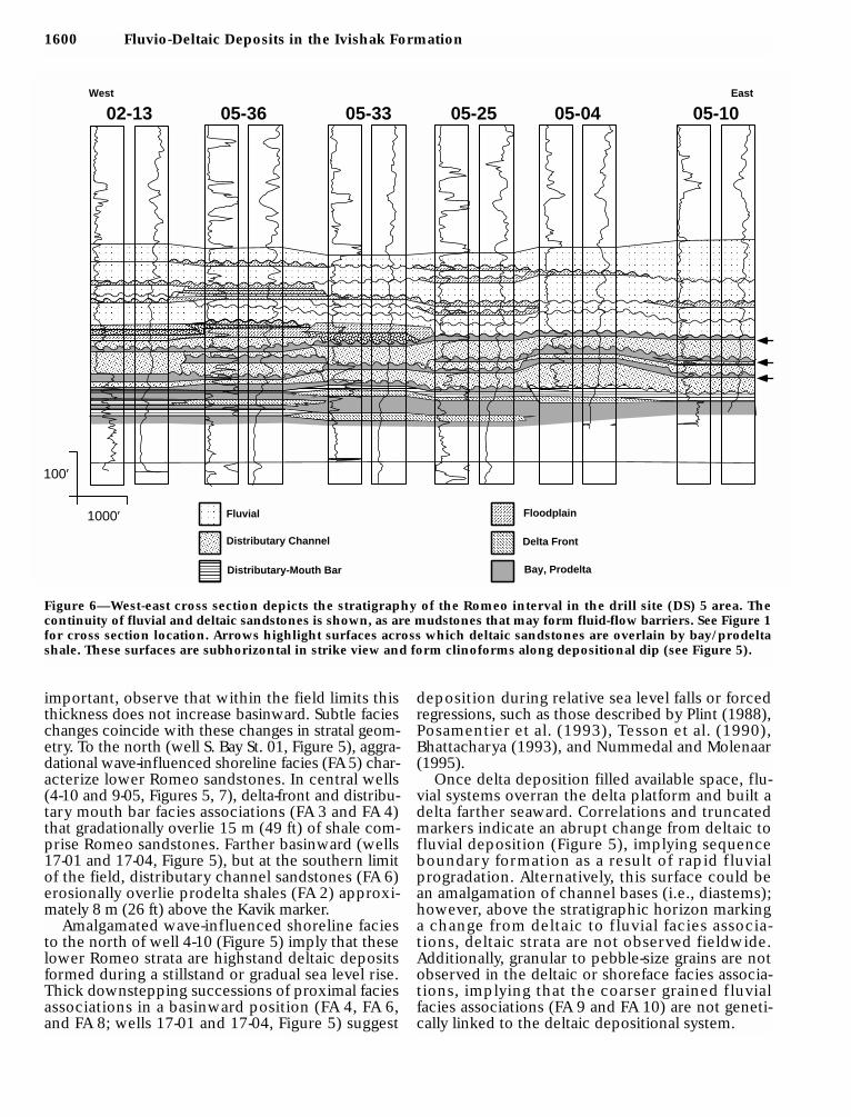
Along depositional strike (Figure 6), the mostobvious feature is the lateral interfingering or juxta-position of sandstone facies (distributary mouth
Tye et al. 1597

bar and distributary channel deposits) with muddierfacies (delta-front and bay/prodelta deposits).Stratification is fairly consistent, but facies associationcorrelations are complex (Figures 5–7) (see alsoLawton et al., 1987). Delta-front deposits (FA 3)pinch out into prodelta shales at delta-lobe margins.Flooding surfaces separate delta-front strata fromoverlying distributary mouth bar and distributary
channel sandstones (wells 5-04, 5-10, Figure 6). Fourto five bay shales are correlated within the lower halfof the Romeo, but only two bay shales extend acrossthe section. No upper Romeo shales correlate acrossthe 6.5-km- (4-mi-) long cross section; moreover, thissection displays both gradational prodelta to delta-front transitions (wells 2-13 to 5-25, Figure 6), aswell as abrupt, sharp-based transitions (wells 5-4
1598 Fluvio-Deltaic Deposits in the Ivishak Formation
RILD
.20 2000
G R
SONI
0
150
150
50
8500
RILD
.20 2000
G R
SONI
0
150
150
50
10,300
10,350
10,400
10,450
10,500
10,550
RILD
.20 2000
G R
SONI
0
150
150
50
8150
8200
8250
8300
8350
8400
RILD.20 2000
G R
SONI
0
150
150
50
8400
8450
8350
8500
8550
8600
8650
RILD.20 2000
G R
SONI
0
150
150
50
8400
8450
8500
8550
8250
8300
8350
8600
8650
RILD.20 2000
G R
SONI
0
150
150
50
8550
8600
8650
8700
8400
8450
8600
8550
8500
8450
8650
8700
8500
8750
8800
8800
8850
8900
8950
8750
9000
9050
RILD
.20 2000
G R
SONI
0
150
150
50
GULL IS. #1 GULL IS. #2 E. BAY ST. #1
S. BAY ST. #1 04-10
09-32
Floodplain
Distributary Channel
Distributary Mouth Bar/Delta Front
Prodelta/Shelf
Fluvial
One Mile
100 ft
North
1
32
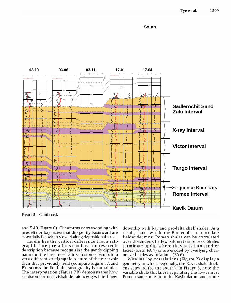
Figure 5—North-south wireline log correlations across Prudhoe Bay field (see Figure 1 for cross section location).Multiple, stacked, coarsening-upward depositional packages representing successive delta-lobe progradationsunderlie nonmarine strata. Surfaces capping coarsening-upward successions and overlain by mudstone are inter-preted as transgressive surfaces of erosion that dip gently (0.3°) to the southeast. Lithofacies constituting thesecoarsening-upward packages become shalier toward the southeast. Note the progradational and downsteppinggeometry of the deltaic and fluvial strata.
Tye et al. 1599
and 5-10, Figure 6). Clinoforms corresponding withprodelta or bay facies that dip gently basinward areessentially flat when viewed along depositional strike.
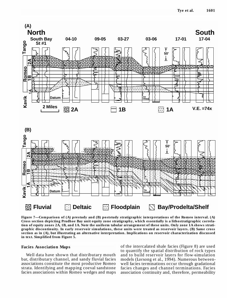
Herein lies the critical difference that strati-graphic interpretations can have on reservoirdescription because recognizing the gently dippingnature of the basal reservoir sandstones results in avery different stratigraphic picture of the reservoirthan that previously held (compare Figure 7A andB). Across the field, the stratigraphy is not tabular.The interpretation (Figure 7B) demonstrates howsandstone-prone Ivishak deltaic wedges interfinger
downdip with bay and prodelta/shelf shales. As aresult, shales within the Romeo do not correlatefieldwide; most Romeo shales can be correlatedover distances of a few kilometers or less. Shalesterminate updip where they pass into sandierfacies (FA 3, FA 4) or are eroded by overlying chan-nelized facies associations (FA 6).
Wireline log correlations (Figure 2) display ageometry in which regionally, the Kavik shale thick-ens seaward (to the south). In Figure 5, note thevariable shale thickness separating the lowermostRomeo sandstone from the Kavik datum and, more
Kavik Datum
Romeo Interval
Tango Interval
Victor Interval
X-ray Interval
Sadlerochit SandZulu Interval
8550
8600
8550
8500
8450
8650
8700
8800
8750
8850
8900
8950
9000
9050
9100
RILD
.20 2000
G R
SONI
0
150
150
50
8900
8950
9000
9050
8700
8750
8800
8550
8600
8650
8850
8700
8750
8800
8850
9100
8900
8950
9000
9050
9100
9150
9200
9150
9200
9250
9300
9350
RILD
.20 2000
G R
SONI
0
150
150
50
RILD
.20 2000
G R
SONI
0
150
150
50
RILD.20 2000
G R
SONI
0
150
150
50
9200
9250
9100
9150
9100
9150
9050
8950
9000
9300
9350
9400
9450
RILD
.20 2000
G R
SONI
0
150
150
50
9250
9300
9150
9200
9050
9100
8950
9000
8900
9350
9400
9450
9500
03-10 03-06 03-11 17-01 17-04
South
Sequence Boundary
Figure 5—Continued.
1600 Fluvio-Deltaic Deposits in the Ivishak Formation
West East
Bay, Prodelta
Fluvial
Distributary Channel
Floodplain
Distributary-Mouth Bar
Delta Front
02-13 05-36 05-33 05-25 05-04 05-10
100′
1000′
Figure 6—West-east cross section depicts the stratigraphy of the Romeo interval in the drill site (DS) 5 area. Thecontinuity of fluvial and deltaic sandstones is shown, as are mudstones that may form fluid-flow barriers. See Figure 1for cross section location. Arrows highlight surfaces across which deltaic sandstones are overlain by bay/prodeltashale. These surfaces are subhorizontal in strike view and form clinoforms along depositional dip (see Figure 5).
important, observe that within the field limits thisthickness does not increase basinward. Subtle facieschanges coincide with these changes in stratal geom-etry. To the north (well S. Bay St. 01, Figure 5), aggra-dational wave-influenced shoreline facies (FA 5) char-acterize lower Romeo sandstones. In central wells(4-10 and 9-05, Figures 5, 7), delta-front and distribu-tary mouth bar facies associations (FA 3 and FA 4)that gradationally overlie 15 m (49 ft) of shale com-prise Romeo sandstones. Farther basinward (wells17-01 and 17-04, Figure 5), but at the southern limitof the field, distributary channel sandstones (FA 6)erosionally overlie prodelta shales (FA 2) approxi-mately 8 m (26 ft) above the Kavik marker.
Amalgamated wave-influenced shoreline faciesto the north of well 4-10 (Figure 5) imply that theselower Romeo strata are highstand deltaic depositsformed during a stillstand or gradual sea level rise.Thick downstepping successions of proximal faciesassociations in a basinward position (FA 4, FA 6,and FA 8; wells 17-01 and 17-04, Figure 5) suggest
deposition during relative sea level falls or forcedregressions, such as those described by Plint (1988),Posamentier et al. (1993), Tesson et al. (1990),Bhattacharya (1993), and Nummedal and Molenaar(1995).
Once delta deposition filled available space, flu-vial systems overran the delta platform and built adelta farther seaward. Correlations and truncatedmarkers indicate an abrupt change from deltaic tofluvial deposition (Figure 5), implying sequenceboundary formation as a result of rapid f luvialprogradation. Alternatively, this surface could bean amalgamation of channel bases (i.e., diastems);however, above the stratigraphic horizon markinga change from deltaic to f luvial facies associa-tions, deltaic strata are not observed fieldwide.Additionally, granular to pebble-size grains are notobserved in the deltaic or shoreface facies associa-tions, implying that the coarser grained f luvialfacies associations (FA 9 and FA 10) are not geneti-cally linked to the deltaic depositional system.
Tye et al. 1601
Facies Association Maps
Well data have shown that distributary mouthbar, distributary channel, and sandy fluvial faciesassociations constitute the most productive Romeostrata. Identifying and mapping coeval sandstonefacies associations within Romeo wedges and maps
of the intercalated shale facies (Figure 8) are usedto quantify the spatial distribution of rock typesand to build reservoir layers for f low-simulationmodels (Lorsong et al., 1994). Numerous between-well facies terminations occur through gradationalfacies changes and channel terminations. Faciesassociation continuity and, therefore, permeability
Figure 7—Comparison of (A) prestudy and (B) poststudy stratigraphic interpretations of the Romeo interval. (A)Cross section depicting Prudhoe Bay unit equity zone stratigraphy, which essentially is a lithostratigraphic correla-tion of equity zones 2A, 1B, and 1A. Note the uniform tabular arrangement of these units. Only zone 1A shows strati-graphic discontinuity. In early reservoir simulations, these units were treated as reservoir layers. (B) Same crosssection as in (A), but illustrating an alternative interpretation. Implications on reservoir characterization discussedin text. Simplified from Figure 5.
2 Miles
(A)
North SouthSouth Bay
St #104-10 09-05 03-27 03-06 17-01 17-04
V.E. =74x
Datum
2A 1B 1A
50’
Fluvial Deltaic Floodplain Bay/Prodelta/Shelf
Datum
50’
(B)
1602 Fluvio-Deltaic Deposits in the Ivishak Formation
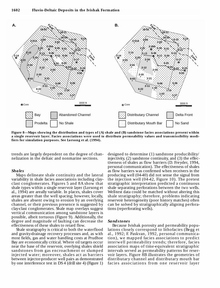
Figure 8—Maps showing the distribution and types of (A) shale and (B) sandstone facies associations present withina single reservoir layer. Facies associations were used to distribute permeability values and transmissibility modi-fiers for simulation purposes. See Lorsong et al. (1994).
Zone
18-0218-11
18-205-15 5-14
5-23
2-01A
2-29A5-35 5-31
5-12
2-02
5-10
5-20
5-225-04
5-06
1-19
5-08
1-20
1-03
2-21
2-116-22
2-20
6-03
2-04
2-23
2-142-10
2-20
2-31
2-09
2-135-345-11
5-36
2-345-25
2-032-12
1-17
5-17
5-33
3000 ftCore
Prodelta No Shale
Bay Abandoned Channel
A.
Zone
Distributary Mouth Bar
Distributary Channel Delta Front
No Sand
3000 ftCore
B.18-02
18-11
18-205-15 5-14
5-23
2-01A
2-29A5-35 5-31
5-12
2-02
5-10
5-20
5-225-04
5-06
1-19
5-08
1-20
1-03
2-21
2-116-22
2-20
6-03
2-04
2-23
2-142-10
2-20
2-31
2-09
2-135-345-11
5-36
2-345-25
2-032-12
1-17
5-17
FaultFault
trends are largely dependent on the degree of chan-nelization in the deltaic and nonmarine sections.
ShalesMaps delineate shale continuity and the lateral
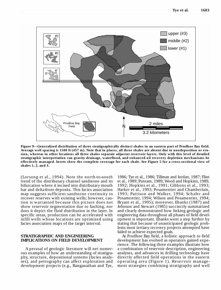
variability in shale facies associations including clay-clast conglomerates. Figures 5 and 8A show thatshale types within a single reservoir layer (Lorsong etal., 1994) are areally variable. In places, shales coverareas greater than the well spacing; however, locally,shales are absent owing to erosion by an overlyingchannel, or their previous presence is suggested byclay-clast conglomerates. Shale map overlays suggestvertical communication among sandstone layers ispossible, albeit tortuous (Figure 9). Additionally, thedegree and magnitude of faulting can decrease theeffectiveness of these shales to retard flow.
Shale stratigraphy is critical to both the waterfloodand gravity-drainage recovery processes and, as withmost fields, gas and water handling costs at PrudhoeBay are economically critical. Where oil targets occurnear the base of the reservoir, overlying shales shieldsandstones from gas encroachment or slumpedinjected water; moreover, shales act as barriersbetween injector-producer well pairs as demonstratedby one interference test in DS 4 (drill site 4) (Figure 1)
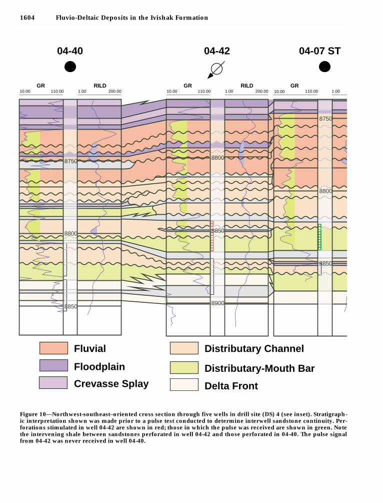
designed to determine (1) sandstone producibility/injectivity, (2) sandstone continuity, and (3) the effec-tiveness of shales as flow barriers (D. Freyder, 1994,personal communication). The effectiveness of shalesas flow barriers was confirmed when receivers in theproducing well (04-40) did not sense the signal fromthe injection well (04-42, Figure 10). The preteststratigraphic interpretation predicted a continuousshale separating perforations between the two wells.Well-test data could be matched without altering thisshale stratigraphy; therefore, problems indicatingreservoir heterogeneity (poor history matches) oftencan be solved by stratigraphically aligning perfora-tions (reperforating wells).
SandstonesBecause Ivishak porosity and permeability popu-
lations closely correspond to lithofacies (Begg etal., 1992; F. Paskvan, 1992, personal communica-tion), we mapped facies associations to predictinterwell permeability trends; therefore, faciesassociation maps of time-equivalent stratigraphicintervals served as permeability patterns for reser-voir layers. Figure 8B illustrates the geometries ofdistributary channel and distributary mouth barfacies associations from one reservoir layer
Tye et al. 1603
(Lorsong et al., 1994). Note the north-to-southtrend of the distributary channel sandstone and itsbifurcation where it incised into distributary mouthbar and delta-front deposits. This facies associationmap suggests sufficient sandstone continuity torecover reserves with existing wells; however, cau-tion is warranted because this picture does notshow reservoir segmentation due to faulting, nordoes it depict the fluid distribution in the layer. Inspecific areas, production can be accelerated withinfill wells whose locations are optimized usingfacies association maps of the target interval.
STRATIGRAPHIC AND ENGINEERINGIMPLICATIONS ON FIELD DEVELOPMENT
A perusal of geologic literature will net numer-ous examples of how an understanding of stratigra-phy, structure, depositional systems (facies analy-ses), and petrography can affect exploration anddevelopment projects (e.g., Ranganathan and Tye,
1986; Tye et al., 1986; Tillman and Jordan, 1987; Flintet al., 1989; Putnam, 1989; Wood and Hopkins, 1989,1992; Hopkins et al., 1991; Gibbons et al., 1993;Harker et al., 1993; Posamentier and Chamberlain,1993; Pattison and Walker, 1994; Schafer andPosamentier, 1994; Wilson and Posamentier, 1994;Bryant et al., 1995); moreover, Ebanks (1987) andJohnson and Stewart (1985) succinctly summarizedand clearly demonstrated how linking geologic andengineering data throughout all phases of field devel-opment is important. Ebanks went a step further bystating that because of unanticipated geologic prob-lems most tertiary recovery projects attempted havefailed to achieve expected goals.
At Prudhoe Bay field, a holistic approach to fielddevelopment has evolved as operators gained expe-rience. The following three examples illustrate howa combination of reservoir description, engineeringanalyses, and advances in drilling technology havedirectly affected field operations in the easternoperating area (Figure 1). Reservoir manage-ment strategies combining stratigraphy and well
2 miles
3.2 kilometers
NPrudhoe Bay
Field
lower (#1)
middle (#2)
upper (#3)
Figure 9—Generalized distribution of three stratigraphically distinct shales in an eastern part of Prudhoe Bay field.Average well spacing is 1500 ft (457 m). Note that in places, all three shales are absent due to nondeposition or ero-sion, whereas in other locations all three shales separate adjacent reservoir layers. Only with this level of detailedstratigraphic interpretation can gravity drainage, waterflood, and enhanced oil recovery depletion mechanisms beeffectively managed. Insets show the complete coverage for each shale. See Figure 5 for a cross-sectional view ofshales 1, 2, and 3.
1604 Fluvio-Deltaic Deposits in the Ivishak Formation
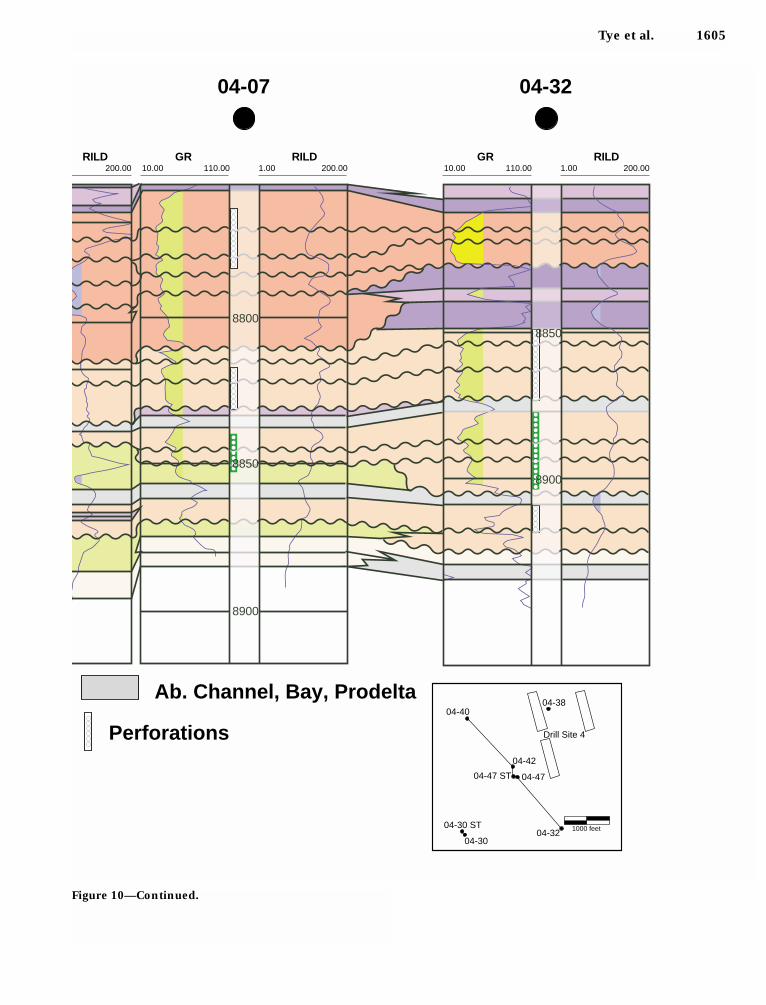
Figure 10—Northwest-southeast–oriented cross section through five wells in drill site (DS) 4 (see inset). Stratigraph-ic interpretation shown was made prior to a pulse test conducted to determine interwell sandstone continuity. Per-forations stimulated in well 04-42 are shown in red; those in which the pulse was received are shown in green. Notethe intervening shale between sandstones perforated in well 04-42 and those perforated in 04-40. The pulse signalfrom 04-42 was never received in well 04-40.
10.00 110.00 200.001.00GR RILD
10.00 110.00 200.001.00GR RILD
10.00 110.00 1.00GR
8800
8750
8900
8800
8800
8750
Fluvial
Floodplain
Crevasse Splay
Distributary Channel
Distributary-Mouth Bar
Delta Front
04-40 04-42 04-07 ST
8850
8850
8850
Tye et al. 1605
200.00RILD
10.00 110.00 200.001.00GR RILD
10.00 200.001.00GR RILD
8900
8800
Ab. Channel, Bay, Prodelta
110.00
Perforations
04-07 04-32
8850
8850
8900
04-40
04-42
04-4704-47 ST
04-38
Drill Site 4
04-30 ST
04-3004-32 1000 feet
Figure 10—Continued.
1606 Fluvio-Deltaic Deposits in the Ivishak Formation
histories focused on the following goals: (1) design-ing producer/injector patterns for maximum efficiency,(2) establishing stratigraphic alignment of perforationsin waterflood injector/producer well pairs, (3) identify-ing remaining reserve targets from well injection/production histories, and (4) using nonconventionalwells to optimize rates and recoveries.
Reserve Target Identification andOptimization: Drill Site-04 WaterfloodPerformance
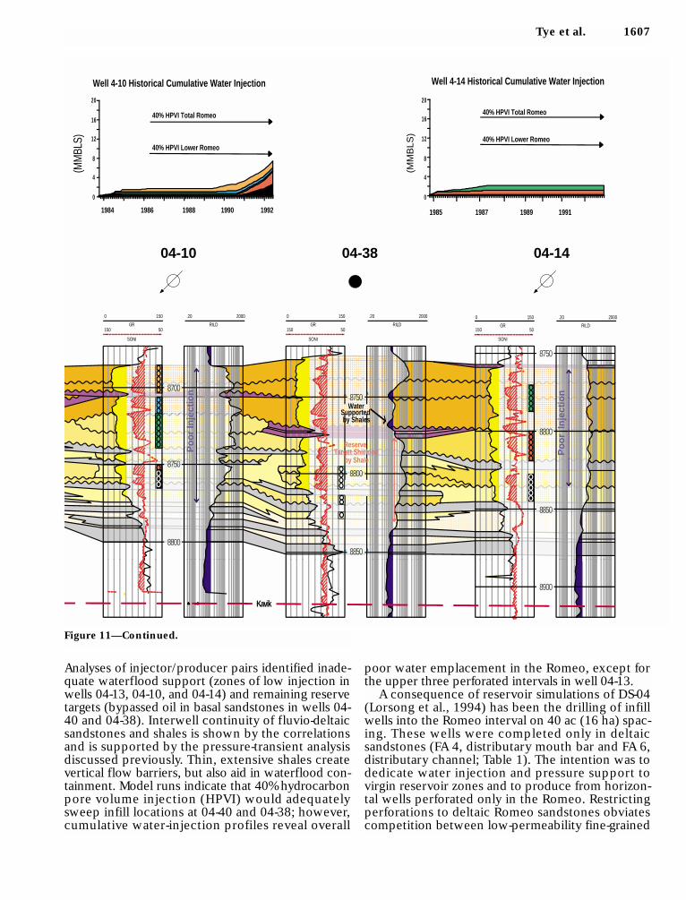
The cross section in Figure 11 illustrates alternat-ing injection and production wells covering a smallpart of the waterflood area in Prudhoe Bay field.
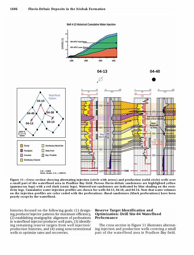
Figure 11—Cross section showing alternating injection (circle with arrow) and production (solid circle) wells overa small part of the waterflood area in Prudhoe Bay field. Porous fluvio-deltaic sandstones are highlighted yellow(gamma-ray logs) with a red slash (sonic logs). Watered-out sandstones are indicated by blue shading on the resis-tivity logs. Cumulative water injection profiles are shown for wells 04-13, 04-10, and 04-14. Note that water volumeson the injection profiles are color coded with the perforations. Basal sandstones (black perforations) have beenpoorly swept by the waterflood.
8750
8800
8850
RILD
.20 2000
GR
SONI
10
150
110
50RILD
.20 2000
GR
SONI
0
150
150
50
8850
8800
8750
Fluvial
Floodplain
Crevasse
Distributary Channel
Distributary Mouth Bar
Delta Front
Bay / Prodelta
WaterfloodPattern
Go
od
Inje
ctio
n
8900 Kavik
Supressed ResistivityDue to 04-13 Injection
Supportedby Shale
PoorInjection
(MM
BLS
)
Well 4-13 Historical Cumulative Water Injection
40% HPVI Total Romeo
40% HPVI Lower Romeo
1986 1988 1990 19920
10
20
30
Target Shielded by Bay Shale
04-13 04-40
V.E. = 240XHoriz. Scale: 1 in. = 1000 ft.
04-13
04-40
04-10
04-38
04-14 Water
Reserve
1600 ft
525m
Tye et al. 1607
Analyses of injector/producer pairs identified inade-quate waterflood support (zones of low injection inwells 04-13, 04-10, and 04-14) and remaining reservetargets (bypassed oil in basal sandstones in wells 04-40 and 04-38). Interwell continuity of fluvio-deltaicsandstones and shales is shown by the correlationsand is supported by the pressure-transient analysisdiscussed previously. Thin, extensive shales createvertical flow barriers, but also aid in waterflood con-tainment. Model runs indicate that 40% hydrocarbonpore volume injection (HPVI) would adequatelysweep infill locations at 04-40 and 04-38; however,cumulative water-injection profiles reveal overall
poor water emplacement in the Romeo, except forthe upper three perforated intervals in well 04-13.
A consequence of reservoir simulations of DS-04(Lorsong et al., 1994) has been the drilling of infillwells into the Romeo interval on 40 ac (16 ha) spac-ing. These wells were completed only in deltaicsandstones (FA 4, distributary mouth bar and FA 6,distributary channel; Table 1). The intention was todedicate water injection and pressure support tovirgin reservoir zones and to produce from horizon-tal wells perforated only in the Romeo. Restrictingperforations to deltaic Romeo sandstones obviatescompetition between low-permeability fine-grained
Figure 11—Continued.
RILD
.20 2000
GR
SONI
0
150
150
50RILD
.20 2000
GR
SONI
0
150
150
50RILD
.20 2000
GR
SONI
0
150
150
50
8800
8750
8700
8850
8800
8750
8750
8800
8850
8900
Po
or
Inje
ctio
n
Po
or
Inje
ctio
n
Kavik
by Shales
WaterSupported
(MM
BLS
)
Well 4-14 Historical Cumulative Water Injection
40% HPVI Total Romeo
40% HPVI Lower Romeo
1985 1987 1989 1991
0
4
8
12
16
20
(MM
BLS)
0
4
8
12
16
20
40% HPVI Total Romeo
40% HPVI Lower Romeo
19921990198819861984
Well 4-10 Historical Cumulative Water Injection
Target Shielded by Shale
Reserve
04-10 04-38 04-14
1608 Fluvio-Deltaic Deposits in the Ivishak Formation
sandstones (FA 4) and overlying high-permeabilitysandstones and conglomerates (FA 6, FA 8, FA 9, andFA 10; Table 1). Additionally, recompletions compris-ing squeeze jobs and reperforations were performed
to ensure stratigraphic and structural agreementbetween perforated zones in injection and produc-tion wells, thus increasing producible Romeoreserves.
9000
8900
8850
8800
No Production09-35
09-35 ConventionalCompletion
100% Production
09-35ANon-Conventional
Completion
Kavik
Basal RomeoSandstones
09-35AHorizontal Sidetrack
09-35Original
B.
8750
8800
8850
8600
8650
8700
8900
TopIvishak
09-34A DedicatedLower Romeo
Horizontal Twin Well
.20
RILD
2000TVD
FEET
150
50150
50 GR
SONIC
04-04Original
Basal RomeoSandstones
100% Production09-34A
100%
Ori
gin
al 0
4-04
Pro
du
ctio
n
A.
0
400
800
1200
1600
2000
09-35 Production 09-35A Production
5/31
/92
1/31
/93
1/31
/94
5/31
/94
09-35 & 09-35AOil and Water Production
Oil
Water
(BBL
S/Da
y)
C.
8936 ft Shale
.20
RILD
2000TVDFEET
150
50150
50 GR
SONIC
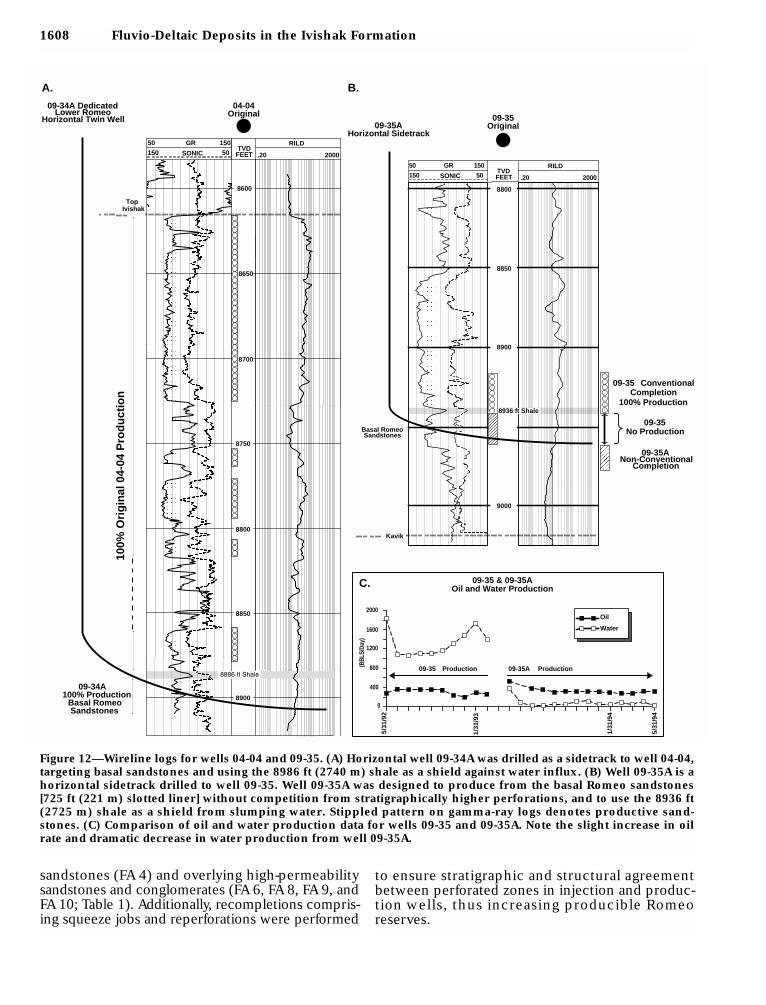
Figure 12—Wireline logs for wells 04-04 and 09-35. (A) Horizontal well 09-34A was drilled as a sidetrack to well 04-04,targeting basal sandstones and using the 8986 ft (2740 m) shale as a shield against water influx. (B) Well 09-35A is ahorizontal sidetrack drilled to well 09-35. Well 09-35A was designed to produce from the basal Romeo sandstones[725 ft (221 m) slotted liner] without competition from stratigraphically higher perforations, and to use the 8936 ft(2725 m) shale as a shield from slumping water. Stippled pattern on gamma-ray logs denotes productive sand-stones. (C) Comparison of oil and water production data for wells 09-35 and 09-35A. Note the slight increase in oilrate and dramatic decrease in water production from well 09-35A.
Tye et al. 1609
11-2
811
-30
11-2
3
FP
FP
FP
IB IB
Fliuds
Fluids
8600
8500
8400
8600
8500
8700
So
uth
wes
tN
ort
hea
st
MW
Dga
mm
a ra
y
12200
12300
12400
12500
12600
12700
12800
12900
13000
13100
13200
13300
13400
13500
13600
13700
TD
B.
894’
of s
lotte
d lin
er
Flu
vial
/Cre
vass
e S
play
Bay
She
lf, P
rode
lta, &
Del
ta F
ront
Dis
trib
utar
y M
outh
Bar
Flo
odpl
ain
Dis
trib
utar
y C
hann
el
Gas
Oil
A.
C.
25’
Fig
ure
13
—(A
) C
ross
sec
tio
n i
llu
stra
tin
g f
acie
s as
soci
atio
n i
nte
rpre
tati
on
s b
etw
een
wel
ls 1
1-2
8 a
nd
11
-23
an
d t
he
pre
dri
llst
rate
gy f
or
pla
cin
g w
ell
11
-30
. T
he
ho
rizo
nta
l tr
ajec
tory
of
11
-30
is
per
pen
dic
ula
r to
th
e cr
oss
sec
tio
n.
(B)
Sch
emat
ic r
epre
-se
nta
tio
n o
f th
e w
ell-
bo
re p
ath
th
rou
gh
dis
trib
uta
ry m
ou
th b
ar s
and
sto
nes
ben
eath
a b
ay s
hal
e. (
C)
MW
D (
mea
sure
d w
hil
ed
rill
ing)
gam
ma-
ray l
og
thro
ugh
dis
trib
uta
ry m
ou
th b
ar s
and
sto
nes
. Gra
y v
s. l
igh
t st
ipp
lin
g d
eno
tes
a 50 A
PI
cuto
ff.
1610 Fluvio-Deltaic Deposits in the Ivishak Formation
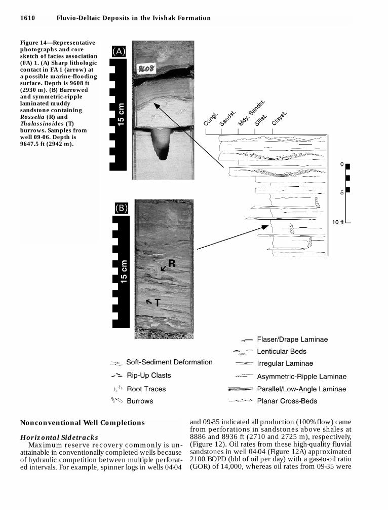
Figure 14—Representativephotographs and coresketch of facies association(FA) 1. (A) Sharp lithologiccontact in FA 1 (arrow) at a possible marine-floodingsurface. Depth is 9608 ft(2930 m). (B) Burrowedand symmetric-ripple laminated muddy sandstone containingRosselia (R) and Thalassinoides (T) burrows. Samples fromwell 09-06. Depth is 9647.5 ft (2942 m).
Nonconventional Well Completions
Horizontal SidetracksMaximum reserve recovery commonly is un-
attainable in conventionally completed wells becauseof hydraulic competition between multiple perforat-ed intervals. For example, spinner logs in wells 04-04
and 09-35 indicated all production (100% flow) camefrom perforations in sandstones above shales at8886 and 8936 ft (2710 and 2725 m), respectively,(Figure 12). Oil rates from these high-quality fluvialsandstones in well 04-04 (Figure 12A) approximated2100 BOPD (bbl of oil per day) with a gas-to-oil ratio(GOR) of 14,000, whereas oil rates from 09-35 were
Tye et al. 1611
300 BOPD (Figure 12B, C). Both wells experiencedhigh (up to 85%) and increasing water cuts.Nonrecovery of oil from underlying, low-permeabil-ity sandstones (approximately 80–200 md) con-stituted bypassed reserves.
To recover bypassed reserves from basal deltaicsandstones, horizontal sidetrack wells, 09-34A and09-35A, were drilled as dedicated lower Romeotwins to wells 04-04 and 09-35 (Figure 12A, B).Distributary mouth bar sandstones were targetedand the well plans were designed to use the 8886 ft(2710 m) shale in well 04-04 and the 8936 ft (2725 m)shale in well 09-35 as shields against water
influx. The placement of the 09-34A horizontalwell bore within deltaic sandstones resulted innew production from this interval at an oil rate of700–800 BOPD and a significant decrease in waterand gas production (water cut 2% and GOR 800).Increased oil rates and a decreased water fractionwere also realized in well 09-35 (Figure 12C).Although spinner logs were not run across thelower Romeo, these wells confirmed the pro-ducibility of basal low-permeability deltaic sand-stones with a low water cut. Established produc-tivity from this stratigraphic interval was thecatalyst for a successful series of dedicated lower
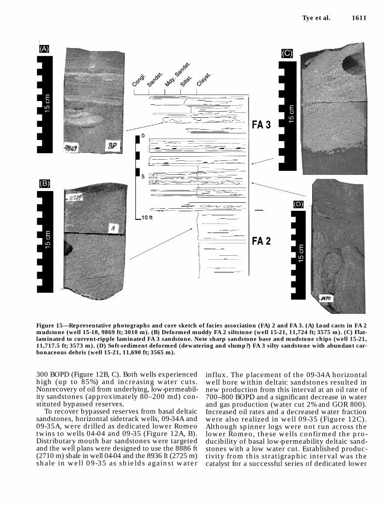
Figure 15—Representative photographs and core sketch of facies association (FA) 2 and FA 3. (A) Load casts in FA 2mudstone (well 15-10, 9869 ft; 3010 m). (B) Deformed muddy FA 2 siltstone (well 15-21, 11,724 ft; 3575 m). (C) Flat-laminated to current-ripple laminated FA 3 sandstone. Note sharp sandstone base and mudstone chips (well 15-21,11,717.5 ft; 3573 m). (D) Soft-sediment deformed (dewatering and slump?) FA 3 silty sandstone with abundant car-bonaceous debris (well 15-21, 11,690 ft; 3565 m).
1612 Fluvio-Deltaic Deposits in the Ivishak Formation
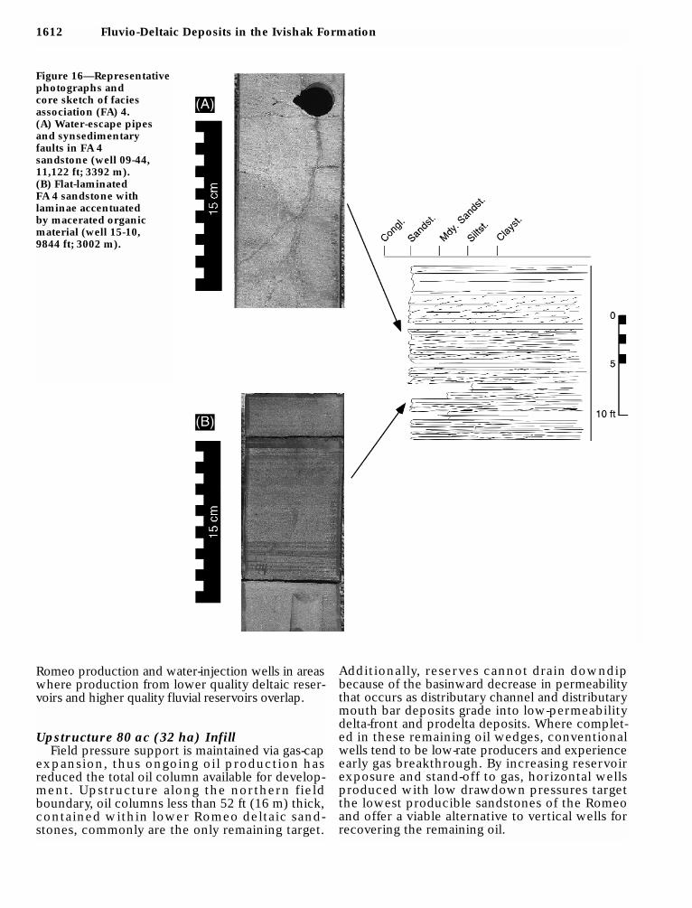
Figure 16—Representativephotographs and core sketch of facies association (FA) 4. (A) Water-escape pipesand synsedimentary faults in FA 4 sandstone (well 09-44,11,122 ft; 3392 m). (B) Flat-laminated FA 4 sandstone with laminae accentuated by macerated organicmaterial (well 15-10, 9844 ft; 3002 m).
Romeo production and water-injection wells in areaswhere production from lower quality deltaic reser-voirs and higher quality fluvial reservoirs overlap.
Upstructure 80 ac (32 ha) InfillField pressure support is maintained via gas-cap
expansion, thus ongoing oil production hasreduced the total oil column available for develop-ment. Upstructure along the northern fieldboundary, oil columns less than 52 ft (16 m) thick,contained within lower Romeo deltaic sand-stones, commonly are the only remaining target.
Additionally, reserves cannot drain downdipbecause of the basinward decrease in permeabilitythat occurs as distributary channel and distributarymouth bar deposits grade into low-permeabilitydelta-front and prodelta deposits. Where complet-ed in these remaining oil wedges, conventionalwells tend to be low-rate producers and experienceearly gas breakthrough. By increasing reservoirexposure and stand-off to gas, horizontal wellsproduced with low drawdown pressures targetthe lowest producible sandstones of the Romeoand offer a viable alternative to vertical wells forrecovering the remaining oil.
Tye et al. 1613
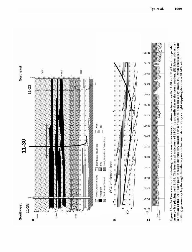
The 11-30 horizontal well (Figure 13) was drilledat one of the few remaining 80 ac (32 ha) locationsdowndip of the gas cap limit. This well illustrateshow a linkage of reservoir description and drillingtechnology can culminate in a successful Romeodevelopment. Prognoses predicted a 19-ft- (6-m-)thick distributary mouth bar sandstone (FA 4) at thebase of the Romeo [8800 ft (2684 m) total verticaldepth, Figure 13A] and an overlying extensive inter-distributary bay shale (FA 7) that could act as ashield from the gas cap. Reservoir-target choices
were optimized using both net sandstone and faciesassociation maps, as well as geostatistical realizationsof coeval facies associations. Potentially gas-conduc-tive faults were avoided through detailed mappingusing three-dimensional seismic data.
The well was designed to achieve a 90° hole angleat casing point in the targeted sandstone, drill out ahorizontal section, and complete with a slotted liner.After setting casing, an 894-ft- (272-m-) long horizon-tal section was drilled entirely within the targetedsandstone (Figure 13B). Of this, 475 ft (144 m) was
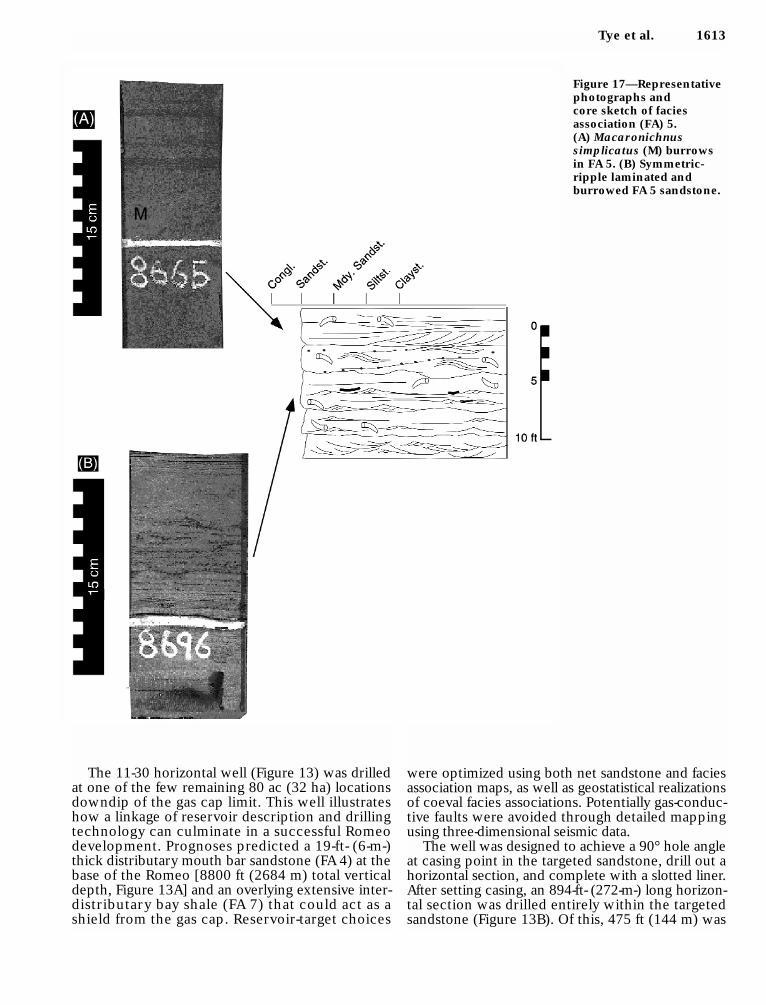
Figure 17—Representativephotographs and core sketch of facies association (FA) 5. (A) Macaronichnus simplicatus (M) burrowsin FA 5. (B) Symmetric-ripple laminated and burrowed FA 5 sandstone.

1614 Fluvio-Deltaic Deposits in the Ivishak Formation
Figure 18—Representativephotographs and core sketch of facies association (FA) 6. (A) Basal FA 6 sandstonecontaining organic debrisand clay clasts (well 09-06,9512 ft; 2901 m). (B) Cross-bedded andasymmetric-ripple laminated FA 6 sandstone(well 09-06, 9499.3 ft; 2897 m).
determined to be net pay (based on gamma-ray cutoffand well cuttings) (Figure 13C). Current productionhas stabilized at 1600 BOPD with a low gas-to-oilratio. This well was largely successful due to animproved understanding of sand-body geometry andthe use of shale as a shield from the gas cap.
CONCLUSIONS
Stratigraphic analyses of basal Ivishak sand-stone deposits in Prudhoe Bay field, Alaska, usingdepositional interpretations based on core dataand concepts of genetic stratigraphy and incor-porating well history data have demonstratedthat the basal section of the reservoir comprisescoarsening-upward sandstone sequences inter-bedded with shales. Strata were deposited in
river-dominated deltas. Mudstones depositedfollowing delta-lobe abandonment separate thedelta lobes. In the eastern portion of the field,f luvio-deltaic deposits are overlain by extensiveflood plain deposits.
Genetic-stratigraphic correlations revised tradition-al lithostratigraphic depictions of tabular reservoirzones between a basal marine shale and overlyingnonmarine strata. This stratigraphic reassess-ment depicts en echelon, off lapping f luviallydominated deltaic wedges. Within a discretedeltaic complex, productive intervals include, inorder of increasing relative quality, (1) distribu-tary mouth bar and (2) distributary channel faciesassociations. Marine and bay shales separatingdelta lobes form locally extensive, but not field-wide, flow barriers. Reservoir compartmentaliza-tion is most pronounced distally, where deltaic
Tye et al. 1615
sandstones are overlain by and pinch out intomarine shale. Proximally, f luvial and deltaicsandstones are juxtaposed across erosional con-tacts, improving reservoir continuity.
Economic oil rates can best be attained andmaintained from horizontal wells targeted at spe-cific reservoir intervals and using laterally exten-sive shales to provide vertical shields from gasand water. Thin, continuous shales strongly con-trol vertical f luid movements within the reser-voir. Detailed modeling of shale continuity, con-nectivity, and placement is vital in accuratelyassessing remaining reserves’ potential and loca-tion. These results could not have been achievedwith reservoir models that did not integratedetailed geology and well history data.
APPENDIX
Detailed Sedimentary Descriptions of FaciesAssociations and Their Depositional Interpretations
Facies Association 1 (Marine Shelf)Dark gray, massive to laminated mudstone interbedded with very
fine grained sandstones comprise this facies association, which isrestricted to the Kavik Member of the Ivishak Formation (Figures 2and 14). Sandstones exhibit symmetric-ripple and low-angle inter-secting laminae. Burrow abundance is high to moderate and decreas-es upward in the sandier facies. Trace fauna include examples ofdwarf Teichichnus, Rosselia, Planolites, and Zoophycos. Pyrite blebsand nodules, up to a few centimeters across, are ubiquitous.
FA (facies association) 1 characterizes the lower Kavik Memberof the Ivishak Formation, and is organized into coarsening- andthickening-upward units ranging from 6 to 100 ft (2 to 30 m)thick. Tops of coarsening-upward subunits are expressed as sharp
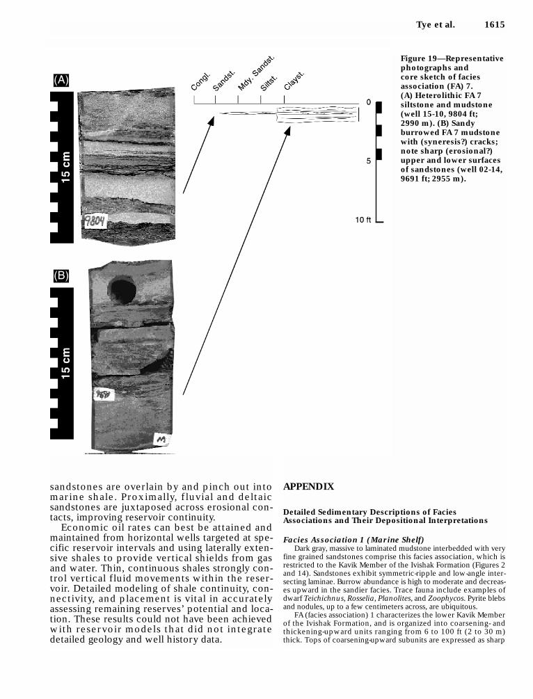
Figure 19—Representativephotographs and core sketch of facies association (FA) 7. (A) Heterolithic FA 7 siltstone and mudstone(well 15-10, 9804 ft; 2990 m). (B) Sandy burrowed FA 7 mudstonewith (syneresis?) cracks;note sharp (erosional?)upper and lower surfacesof sandstones (well 02-14,9691 ft; 2955 m).
1616 Fluvio-Deltaic Deposits in the Ivishak Formation
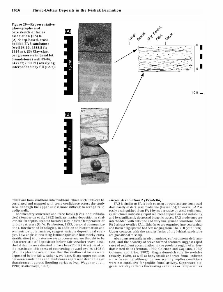
Figure 20—Representativephotographs and core sketch of facies association (FA) 8. (A) Sharp-based, cross-bedded FA 8 sandstone(well 03-10, 9588.5 ft; 2924 m). (B) Clay-clastconglomerate in basal FA8 sandstone (well 09-06,9477 ft; 2890 m) overlyinginterbedded bay fill (FA 7).
transitions from sandstone into mudstone. Three such units can becorrelated and mapped with some confidence across the studyarea, although the upper unit is more difficult to recognize inupdip wells.
Sedimentary structures and trace fossils (Cruziana ichnofa-cies) (Pemberton et al., 1992) indicate marine deposition in shal-low-shelfal depths. Stunted burrows may indicate temperature orturbidity stresses (G. W. Pemberton, 1993, personal communica-tion). Interbedded lithologies, in addition to bioturbation andsymmetric-ripple laminae, suggest variable depositional ener-gies. Low-angle intersecting laminae (possible hummocky cross-stratification) imply storm-wave processes and are thought to becharacteristic of deposition below fair-weather wave base.Shelfal depths are estimated to have been 250 ft (76 m) based onthe maximum thickness of coarsening-upward cycles ≤108 ft(≤33 m) plus the assumption that the shallowest facies weredeposited below fair-weather wave base. Sharp upper contactsbetween sandstones and mudstones represent deepening orabandonment across flooding surfaces (van Wagoner et al.,1990; Bhattacharya, 1993).
Facies Association 2 (Prodelta)FA 2 is similar to FA 1; both coarsen upward and are composed
dominantly of dark gray mudstone (Figure 15); however, FA 2 iseasily distinguished from FA 1 by its pervasive physical sedimenta-ry structures indicating rapid sediment deposition and instabilityand by significantly decreased biogenic traces. FA 2 mudstones areinterbedded with siltstone and very fine grained sandstone beds.FA 2 always overlies FA 1. Lithofacies are organized into coarsening-and thickening-upward bed sets ranging from 6 to 60 ft (2 to 18 m).Upper contacts with the sandier facies of the Ivishak sandstoneare gradational to sharp.
Abundant normally graded laminae, soft-sediment deforma-tion, and the scarcity of wave-formed features suggest rapidrates of sediment accumulation in the prodelta region of a river-dominated delta (Scruton, 1960; Coleman and Gagliano, 1965;Coleman and Prior, 1982). Magnesium-rich siderite nodules(Mozely, 1989), as well as body fossils and trace fauna, indicatea marine setting, although burrow scarcity implies conditionswere not conducive for prolific faunal activity. Suppressed bio-genic activity reflects fluctuating salinities or temperatures

Tye et al. 1617
combined with a large suspended-sediment load and rapiddeposition. Much of the sediment probably was depositedthrough gravitational sett l ing from suspended-sedimentplumes. Symmetric-ripple laminations suggest minor rework-ing by storm waves and deposition below fair-weather wavebase. Dewatering and loading features resulted from sedimentinstabilities and density contrasts between rapidly depositedclay, silt, and sand. Maximum water depths approached 213 ft(65 m).
Facies Association 3 (Delta Front)FA 3 comprises dominantly dark gray mudstone and very fine
grained sandstone (Figure 15). These lithologies form coarsening-upward or irregularly bedded packages up to 37 ft (12 m) thick.Sandstone beds may reach 3 ft (1 m) thick, are commonly sharp basedwith a mud chip lag and are normally graded. FA 3 gradationallyoverlies FA 2 and the contact is placed where sandstone exceedssiltstone abundance; however, in places, FA 3 is missing. At theselocations, FA 2 mudstone is abruptly overlain by FA 4 sandstone.In a few cores, FA 3 is sharply overlain by FA 2.
A delta-front depositional setting is suggested for FA 3.Lithologies and sedimentary structures indicate deposition inwater depths shallower than those inferred for FA 2 and FA 1(<100 ft; 30 m). Asymmetric-ripple laminations associated withnormally graded laminae imply alternating traction-current andsuspension deposition. Periodic rapid sediment accumulation isindicated by climbing current-ripple laminae. Rare wave-ripplelamination and hummocky cross-stratification indicate the minorinfluence of periodic storms. Soft-sediment deformation featuresare ubiquitous, and a nearly complete lack of trace fauna indicateinhospitable conditions caused by substrate instability, turbidity,salinity, or energy stresses.
Facies Association 4 (Distributary Mouth Bar)FA 4 is dominantly sandstone and ranges from 3 to 43 ft (1 to
13 m) in thickness. FA 4 generally exhibits an upward increase ingrain size from very fine to fine-grained sandstone. Sandstones aremassive to parallel laminated. Disseminated carbonaceous debris(“coffee grounds”) drape and accentuate laminae and thin beds.Cross lamination is rare (Figure 16). Soft-sediment deformation
Figure 21—Representativephotographs and core sketch of facies association (FA) 9 and FA10. (A) Cross-bedded FA 9sandstone (well 03-06, 9782 ft; 2983 m). (B) Variably rounded black, gray, and white chert pebbles in FA 10 (well 03-10, 9475 ft; 2889 m).
1618 Fluvio-Deltaic Deposits in the Ivishak Formation
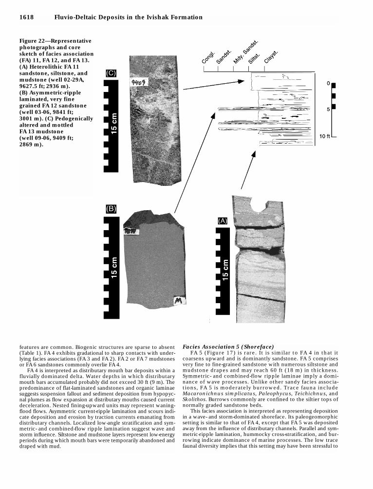
Figure 22—Representativephotographs and coresketch of facies association(FA) 11, FA 12, and FA 13.(A) Heterolithic FA 11sandstone, siltstone, andmudstone (well 02-29A,9627.5 ft; 2936 m). (B) Asymmetric-ripplelaminated, very finegrained FA 12 sandstone(well 03-06, 9841 ft; 3001 m). (C) Pedogenicallyaltered and mottled FA 13 mudstone (well 09-06, 9409 ft; 2869 m).
features are common. Biogenic structures are sparse to absent(Table 1). FA 4 exhibits gradational to sharp contacts with under-lying facies associations (FA 3 and FA 2). FA 2 or FA 7 mudstonesor FA 6 sandstones commonly overlie FA 4.
FA 4 is interpreted as distributary mouth bar deposits within afluvially dominated delta. Water depths in which distributarymouth bars accumulated probably did not exceed 30 ft (9 m). Thepredominance of flat-laminated sandstones and organic laminaesuggests suspension fallout and sediment deposition from hypopyc-nal plumes as flow expansion at distributary mouths caused currentdeceleration. Nested fining-upward units may represent waning-flood flows. Asymmetric current-ripple lamination and scours indi-cate deposition and erosion by traction currents emanating fromdistributary channels. Localized low-angle stratification and sym-metric- and combined-flow ripple lamination suggest wave andstorm influence. Siltstone and mudstone layers represent low-energyperiods during which mouth bars were temporarily abandoned anddraped with mud.
Facies Association 5 (Shoreface)FA 5 (Figure 17) is rare. It is s imilar to FA 4 in that i t
coarsens upward and is dominantly sandstone. FA 5 comprisesvery fine to fine-grained sandstone with numerous siltstone andmudstone drapes and may reach 60 ft (18 m) in thickness.Symmetric- and combined-flow ripple laminae imply a domi-nance of wave processes. Unlike other sandy facies associa-tions, FA 5 is moderately burrowed. Trace fauna includeMacaronichnus simplicatus, Paleophycus, Teichichnus, andSkolithos. Burrows commonly are confined to the siltier tops ofnormally graded sandstone beds.
This facies association is interpreted as representing depositionin a wave- and storm-dominated shoreface. Its paleogeomorphicsetting is similar to that of FA 4, except that FA 5 was depositedaway from the influence of distributary channels. Parallel and sym-metric-ripple lamination, hummocky cross-stratification, and bur-rowing indicate dominance of marine processes. The low tracefaunal diversity implies that this setting may have been stressful to
Tye et al. 1619
organisms, possibly reflecting a deltaic influence (G. W.Pemberton, 1993, personal communication).
Facies Association 6 (Distributary Channel)FA 6 is common in the lower and middle portions of the Romeo
interval in all wells and commonly erosionally overlies FA 4 or FA 3(rarely, FA 2). FA 6 is dominantly a fine-grained sandstone withminor siltstone and claystone (Figure 18). FA 6 may reach 60 ft (18m) in thickness and can be subdivided into a series of stacked fining-upward subunits of roughly 10 ft (3 m) thick. Scoured bases markedby mud-chip lags up to 0.3 ft (0.1 m) thick are common. Fining-upward units show an upward transition from cross-bedding to par-allel stratification to ripple-laminated beds.
FA 6 is interpreted as distributary channel deposits. Channelerosion is indicated by the scoured bases and the presence of abasal lag. Fining-upward units represent waning energy conditionsfollowing flood passage or as the channel is progressively filled.Sedimentary structures indicate unidirectional flow. Multiple fining-upward units suggest aggradational stacking of channel sand-stones. Juxtaposition of FA 6 with shallow-marine or deltaic faciesassociations suggests that the channels were deltaic distributariesrather than fluvial channels.
Fining-upward packages 3–9 ft (1–3 m) in thickness repre-sent relatively complete cycles of distributary channel deposi-tion and abandonment; therefore, these thicknesses approxi-mate paleodistributary channel depths. Thicker occurrences ofFA 6 (i.e., up to 59 ft; 18 m) represent stacked distributary chan-nel deposits. Where distributary channel deposits overlie FA 2,an anomalous facies break is indicated (shallow-water faciesover deep-water facies). The absence of delta-front, distributarymouth bar, or shoreface deposits (i.e., FA 3, FA 4, FA 5) possiblyindicate (1) a relative drop in sea level, (2) exceptional distribu-tary channel progradation and scour, (3) slumping on an unsta-ble delta front, or (4) some combination of these processes.
Facies Association 7 (Swamp, Marsh, InterdistributaryBay, Bay)
Dark- to medium-gray heterolithic claystone and siltstone andminor sandstone comprise FA 7 (Figure 19). FA 7 may range up to20 ft (6 m) thick and caps either FA 4, FA 5, or FA 6. More com-monly, FA 7 is sharp-based and 1–5 ft (0.3–1.5 m) thick. FA 7 canbe gradationally overlain by FA 3 or FA 4 or erosively capped byFA 6 or FA 7.
Claystone to sandstone lithofacies are very thinly interbed-ded. Siltstones are commonly normally graded. Sandstones aresymmetrically and asymmetrically ripple laminated and mayform lenticular beds averaging 1 in. (2.5 cm) thick. Other fea-tures include small-scale loading, mud cracks, and syneresiscracks. Fractures are common. Rare trace fossils includeArenicolites.
FA 7 is interpreted as having been deposited in a shallow-watersubtidal setting. The presence of starved symmetric- and asymmetric-ripple laminations suggests wave and tidal processes affectedthese areas. Syneresis cracks may indicate brackish conditions(Plummer and Gostin, 1981; Bhattacharya and Walker, 1992). Thelinkage with facies associations 4 and 6 suggests a muddy deltaicplain. Depositional environments could include interdistributarybays or larger bays fringing a delta lobe, poorly drained swamps,and marshes.
Facies Association 8 (Fluvial Channel)This facies association comprises multiple, fining-upward units
of medium- to fine-grained sandstones that individually average10–15 ft (3–5 m) in thickness (Figure 20). Amalgamated units upto 42 ft (13 m) thick occur.
Fining-upward subunits have sharp to erosional bases common-ly mantled by a lag of mudstone chips, siderite clasts, chert peb-bles, and granules. Medium-grained sandstones are predominantly
trough and planar-tabular cross-bedded in sets 1–3 ft (0.3–1 m)thick. Fine-grained sandstone commonly is cross-bedded to flatstratified. Laminated to asymmetric current-rippled very finegrained sandstone constitutes a minor proportion of FA 8.Carbonaceous material usually is absent. Thin units of siltstoneand claystone may cap the fining-upward subunits.
FA 8 is most common in the middle and upper portions of theRomeo interval. It is distinguished from FA 6 by its greater pro-portion of medium-grained sandstone, the presence of chertgranules and pebbles, and lack of carbonaceous material. FA 8also occurs at a higher stratigraphic position. FA 8 commonly over-lies FA 4, FA 6, or FA 7.
FA 8 is interpreted as a fluvial-channel deposit. Its coarse-grained texture and lack of association with deltaic depositsindicates a nonmarine depositional setting. The high proportionof sandstone, numerous scours, internal stratification, and thelack of inclined mudstone drapes (i.e., lateral accretion sets)suggest deposition in low-sinuosity, sandy, braided-river chan-nels approximately 15 ft (5 m) deep.
Facies Association 9 (Fluvial Channel)FA 9 consists of stacked, sharp to erosional based, fining-
upward units of coarse- to fine-grained sandstone with interbed-ded pebbly sandstone and sandy conglomerate (Figure 21). Itaverages 10–20 ft (3–6 m) in thickness. The maximum thicknessobserved is 15 m (46 ft). Conglomerates are commonly poorlysorted and matrix-supported (medium-grained sandstone).Pebbly sandstone may be draped by ripple-laminated very finegrained sandstone, siltstone, and thin mudstone layers. Cobble-size material is rare.
Sandy conglomerates and pebbly sandstones are poorly stratifiedto cross-bedded. Pebbles are well rounded and maximum clast sizeis approximately 0.4 in. (1 cm). Cross sets ranging from a few to 11in. (30 cm) thick contain normally graded avalanche beds, creatinga distinct arrangement of conglomerate/sandstone couplets.
This facies association represents the coarse-grained pebblydeposits of fluvial channels. Thin conglomerates (pebble andclay clast) at the bottoms of sharp-based sandstone beds corre-spond to channel-lag deposits. Interbedded conglomerate, peb-bly sandstone, and sandstone represent channel-bar deposits.Conglomerate-sandstone stratification is formed by bar migrationand aggradation as sandy bed forms accrete onto conglomerate-armored bar margins.
Facies Association 10 (Fluvial Channel)FA 10 comprises erosionally or sharp-based poorly stratified
conglomerate and sandy conglomerate (Figure 21). Distinct bed-ding contacts are difficult to recognize owing to the large grainsizes. Pebbles are well rounded and comprise dense and micro-porous chert, and rock fragments (mostly sedimentary). Clast sizesapproach 1 in. (3 cm) in diameter. FA 10 is a minor facies associa-tion restricted to the uppermost part of the Romeo interval.Erosional surfaces and coarse-grained textures suggest FA 10 rep-resents coarse-grained channel and bar deposits.
Facies Association 11 (Abandoned Channel)FA 11 comprises rare successions of gradationally fining-
upward interbedded very fine grained sandstone, siltstone, andmudstone (Figure 22) that may reach 9 ft (3 m) in thickness.Claystone and siltstone constitute the majority of FA 11 with veryfine grained sandstone and minor fine-grained sandstone compris-ing the remainder. Asymmetric-ripple laminae and soft-sedimentdeformation are common. FA 11 gradationally overlies facies asso-ciations 6, 8, 9, and, rarely, 10. FA 11 is most commonly associatedwith FA 6 and FA 8.
Based on both its fine-grained composition and the intimateand gradational relationship with underlying interpreted channel

sandstones, this heterolithic facies association is interpreted asabandoned channel fill. Asymmetric- (current) ripple lamina-tions and soft-sediment deformation are compatible with low-energy and fluctuating fluvial processes. Fining-upward texturaltrends imply progressively lower depositional energies as thechannels were abandoned. Atkinson et al. (1988) noted thatabandoned channel fills grade upward into flood-plain deposits(our FA 13).
Facies Association 12 (Crevasse Splay, LacustrineDelta, Natural Levee, Bayhead Delta)
Interbedded lower coarse- to medium-grained sandstone, cross-stratified fine-grained sandstone, very fine grained asymmetric-ripplelaminated sandstone, and siltstone and claystone comprise FA 12(Figure 22). Sandstones also exhibit small-scale loading features.Occurrences may either coarsen or fine upward and reach 10 ft(3 m) in thickness.
The dominance of asymmetric- (current) ripple laminationsand loading features and lack of wave-formed sedimentary struc-tures and marine traces suggest rapid deposition from unidirec-tional flows in a nonmarine setting. Association with nonmarineto marginal marine shales suggests that these deposits representoverbank deposition on alluvial and deltaic plains such as natural-levee, crevasse-splay, lacustrine-delta, or bayhead deltaic envi-ronments.
Facies Association 13 (Alluvial Flood Plain)FA 13 contains mudstone and siltstone with very minor sand-
stone (Figure 22). Thicknesses average 4.5 ft (1.4 m), but mayreach 30 ft (9 m). The dominant lithofacies is laminated, greento brown mudstone that commonly passes upward into mud-stone characterized by mud cracks, root mottling, swelling clay,slickensides, and diagenetic mottling. Mud cracks may be filledwith siltstone or sandstone. Laminated to mottled units may formdistinct cycles 10–20 ft (3–6 m) thick. Rarely, mudstones have adistinct red coloration. FA 13 commonly is intercalated with faciesassociations 8, 9, 10, and 12 and noticeably absent within the basalIvishak.
FA 13 is nonmarine in origin. Well-laminated mudstones implylow-energy subaqueous deposition, probably in freshwater lakes.The transition into mudstones containing abundant swelling claysis interpreted as representing periods when the lakes were driedor filled and sediments were exposed to subaerial processes (e.g.,pedogenesis). Thicknesses of laminated to mottled mudstonepackages may bear some relationship to paleolake depths.Considering compaction, lakes were a few meters deep. Red col-oration may indicate oxygenation during subaerial exposure.Atkinson et al. (1988) interpreted the mottled lithofacies as imma-ture paleosols (gley to pseudogley) reflecting a flood plain charac-terized by high sedimentation rates and seasonal fluctuation ingroundwater levels.
REFERENCES CITEDAtkinson, C. D., P. N. Trumbly, and M. C. Kremer, 1988,
Sedimentology and depositional environments of the Ivishaksandstone, Prudhoe Bay field, North Slope, Alaska, in A. J.Lomando and P. M. Harris, eds., Giant oil and gas fields: SEPMCore Workshop no. 12, p. 561–613.
Atkinson, C. D., J. H. McGowen, S. Bloch, L. L. Lundell, and P. N.Trumbly, 1990, Braidplain and deltaic reservoir, Prudhoe Bay,Alaska, in J. H. Barwis, J. G. McPherson, and R. J. Studlick, eds.,Sandstone petroleum reservoirs: New York, Springer-Verlag, p. 7–29.
Begg, S. H., E. R. Gustason, and M. W. Deacon, 1992,Characterization of a fluvial-dominated delta: zone 1 of the
Prudhoe Bay field: Society of Petroleum Engineers 67th AnnualTechnical Conference and Exhibition, paper SPE 24698, p. 351–364.
Bellamy, J. R. W., 1993, Multidisciplinary team approach to reservoirdescription in a fluvio-deltaic reservoir: zone 1/2A, Prudhoe Bayfield: Society of Petroleum Engineers Western Regional Meeting,paper SPE 26120, p. 749.
Bhattacharya, J. P., 1993, The expression and interpretation ofmarine flooding surfaces and erosional surfaces in core;examples from the Upper Cretaceous Dunvegan Formation inthe Alberta foreland basin, in C. P. Summerhayes and H. W.Posamentier, eds., Sequence stratigraphy and facies associations:International Association of Sedimentologists Special Publicationno. 18, p. 125–160.
Bhattacharya, J. P., and H. W. Posamentier, 1994, Sequencestratigraphic and allostratigraphic applications in the Albertaforeland basin, in G. D. Mossop and I. Shetsen, eds, Geologicalatlas of the Western Canada sedimentary basin: Canadian Societyof Petroleum Geologists and Alberta Research Council, p.407–412.
Bhattacharya, J. P., and R. G. Walker, 1992, Deltas, in R. G. Walkerand N. P. James, eds., Facies models response to sea levelchange: Geological Association of Canada, St. John’s,Newfoundland, Canada, p. 157–177.
Bhattacharya, J. P., R. S. Tye, and J. A. Lorsong, 1994, Cutting up thelayer cake: improved reservoir stratigraphy of a Permo–Triassicriver-dominated lowstand delta, Prudhoe Bay, Alaska: AAPGHedberg Research Conference Proceedings, Applications ofsequence stratigraphy to oil field development: Sept. 5–8, Paris,France, 6 p., unpaginated.
Brown, L. F., 1969, Geometry and distribution of fluvial and deltaicsandstones (Pennsylvanian and Permian), north-central Texas:Transactions of the Gulf Coast Association of GeologicalSocieties, v. 19, p. 23–47.
Bryant, I. D., C. W. Greenstreet, and W. R. Voggenreiter, 1995,Integrated 3-D geological modeling of the C1 sands reservoir,Maui field, offshore New Zealand: AAPG Bulletin, v. 79, no. 3, p. 351–374.
Coleman, J. M., 1966, Ecological changes in a massive fresh-waterclay sequence: Transactions of the Gulf Coast Association ofGeological Societies, v. 16, p. 159–174.
Coleman, J. M., and S. M. Gagliano, 1965, Sedimentary structures:Mississippi River deltaic plain: SEPM Special Publication 12, p. 133–148.
Coleman, J. M., and D. B. Prior, 1982, Deltaic environments ofdeposition, in P. A. Scholle and D. Spearing, eds., Sandstonedepositional environments: AAPG Memoir 31, p. 139–178.
Crowder, R. K., 1990, Permian and Triassic sedimentation in thenortheastern Brooks Range, Alaska: deposition of the SadlerochitGroup: AAPG Bulletin, v. 74, no. 9, p. 1351–1370.
Detterman, R. L., 1970, Sedimentary history of the Sadlerochit andShublik formations in northeastern Alaska, in W. L. Adkison andM. M. Brosge, eds., Proceedings of the Geological Seminar on theNorth Slope of Alaska: AAPG Pacific Section, p. O1–O13.
Ebanks, W. J., Jr., 1987, Geology in enhanced oil recovery, inR. W. Tillman and K. J. Weber, eds., Reservoir sedimentology:SEPM Special Publication no. 40, p. 1–14.
Eckelmann, W. R., R. J. Dewitt, and W. L. Fisher, 1975, Prediction offluvial-deltaic reservoir geometry, Prudhoe Bay field, Alaska:Proceedings of the 9th World Petroleum Congress, v. 2, p. 223–227.
Fisher, W. L., L. F. Brown, Jr., A. J. Scott, and J. H. McGowen, 1969,Delta systems in the exploration for oil and gas: Austin, Texas,Bureau of Economic Geology, The University of Texas at Austin,78 p.
Flint, S., D. J. Stewart, and E. D. van Riessen, 1989, Reservoirgeology of the Sirikit oilfield, Thailand: lacustrine deltaicsedimentation in a Tertiary intermontaine basin, in M. K. G.Whateley and K. T. Pickering, eds., Deltas: sites and traps forfossil fuels: Geological Society Special Publication 41, p. 223–237.
1620 Fluvio-Deltaic Deposits in the Ivishak Formation

Tye et al. 1621
Frazier, D. E., 1974, Depositional episodes: their relationship to theQuaternary stratigraphic framework in the northwestern portionof the Gulf basin: Bureau of Economic Geology, The Universityof Texas at Austin, Geologic Circular 74-1, 28 p.
Galloway, W. E., 1989, Genetic stratigraphic sequences in basinanalysis I: architecture and genesis of flooding-surface boundeddepositional units: AAPG Bulletin, v. 73, p. 125–142.
Gibbons, K., T. Hellem, A. Kjemperud, S. D. Nio, and K. Vebenstad,1993, Sequence architecture, facies development and carbonate-cemented horizons in the Troll field reservoir, offshore Norway,in M. Ashton, ed., Advances in reservoir geology: GeologicalSociety Special Publication no. 69, p. 1–31.
Harker, S. D., K. A. Mantel, D. J. Morton, and L. A. Riley, 1993, Thestratigraphy of Oxfordian–Kimmeridgian (Late Jurassic) reservoirsandstones in the Witch Ground graben, United Kingdom NorthSea: AAPG Bulletin, v. 77, no. 10, p. 1693–1709.
Hopkins, J. C., J. M. Wood, and F. F. Krause, 1991, Waterfloodresponse of reservoirs in an estuarine valley fill: upper ManvilleG, U, and W pools, Little Bow field, Alberta, Canada: AAPGBulletin, v. 75, no. 6, p. 1064–1088.
Hunt, D., and M. E. Tucker, 1992, Stranded parasequences and theforced regressive wedge systems tract: deposition during base-level fall: Sedimentary Geology, v. 81, p. 1–9.
Jamison, H. C., L. D. Brockett, and R. A. McIntosh, 1980, PrudhoeBay—a ten year perspective, in M. T. Halbouty, ed., Giant oil andgas fields of the decade: AAPG Memoir 30, p. 289–310.
Johnson, H. D., and D. J. Stewart, 1985, Role of clasticsedimentology in the exploration and production of oil and gasin the North Sea, in P. J. Brenchley and B. P. J. Williams, eds.,Sedimentology recent developments and applied aspects:London, Geological Society, p. 249–310.
Jones, H. P., and R. G. Speers, 1976, Permo-Triassic reservoirs ofPrudhoe Bay field, North Slope Alaska: AAPG Memoir 24, p. 23–50.
Lawton, T. F., G. W. Geehan, and B. J. Voorhees, 1987, Lithofaciesand depositional environments of the Ivishak Formation,Prudhoe Bay field, in I. Tailleur and P. Weimer, eds., AlaskanNorth Slope geology: SEPM Pacific Section, v. 10, p. 61–76.
Lorsong, J. A., J. P. Bhattacharya, and R. S. Tye, 1994, Using facies todistribute reservoir properties: hybrid models of fluvio-deltaicdeposits in Prudhoe Bay field, Alaska (abs.): AAPG AnnualConvention Program with Abstracts, p. 201.
Loutit, T. S., J. Hardenbol, P. R. Vail, and G. R. Baum, 1988,Condensed sections: the key to age-dating and correlation ofcontinental margin sequences, in C. K. Wilgus, B. S. Hastings, C. G. St. C. Kendall, H. W. Posamentier, C. A. Ross, and J. C. van Wagoner, eds., Sea-level changes: an integrated approach:SEPM Special Publication no. 42, p. 183–213.
McGowen, J. H., and S. Bloch, 1985, Depositional facies, diagenesis,and reservoir quality of the Ivishak Sandstone (SadlerochitGroup), Prudhoe Bay field (abs.): AAPG Bulletin, v. 69, p. 286.
McGowen, J. H., S. Bloch, and D. Hite, 1987, Depositional facies,diagenesis, and reservoir quality of Ivishak Sandstone(Sadlerochit Group), Prudhoe Bay field (abs.), in I. Tailleur and P. Weimer, eds., Alaskan North Slope geology: SEPM PacificSection, v. 1, p. 84.
McMillen, K. J., and M. D. Colvin, 1987, Facies correlation and basinanalysis of the Ivishak Formation, Arctic National WildlifeRefuge, Alaska, in I. Tailleur and P. Weimer, eds., Alaskan NorthSlope geology: SEPM Pacific Section, v. 50, p. 381–390.
Melvin, J., and A. S. Knight, 1984, Lithofacies, diagenesis andporosity of the Ivishak Formation, Prudhoe Bay area, Alaska, inD. A. McDonald and R. C. Surdam, eds., Clastic diagenesis: AAPGMemoir 37, p.347–365.
Morgridge, D. L., and W. B. Smith, Jr., 1972, Geology and discoveryof Prudhoe Bay field, eastern Arctic slope, Alaska, in R. E. King,ed., Stratigraphic oil and gas fields: AAPG Memoir 16, p. 489–501.
Mozely, P. S., 1989, Relation between depositional environment andthe elemental composition of early diagenetic siderite: Geology,v. 17, p. 704–706.
Naidu, A. S., and T. C. Mowatt, 1975, Depositional environmentsand sediment characteristics of the Colville and adjacent deltas,northern Arctic Alaska, in M. L. Broussard, ed., Deltas: HoustonGeological Society, p. 283–309.
Nummedal, D., and C. M. Molenaar, 1995, Sequence stratigraphy oframp-setting strand plain successions: the Gallup Sandstone,New Mexico, in J. C. van Wagoner and G. T. Bertram, eds.,Sequence stratigraphy of foreland basin deposits: outcrop andsubsurface examples from the Cretaceous of North America:AAPG Memoir 64, p. 277–310.
Ori, G. G., 1993, Continental depositional systems of the Quaternaryof the Po Plain (northern Italy): Sedimentary Geology, v. 83, p. 1–14.
Orton, G. J., and H. G. Reading, 1993, Variability of deltaic processesin terms of sediment supply, with particular emphasis on grainsize: Sedimentology, v. 40, p. 475–512.
Pattison, S. A. J., and R. G. Walker, 1994, Incision and filling of alowstand valley: late Albian Viking Formation at Crystal, Alberta,Canada: Journal of Sedimentary Research, v. B64, no. 3, p. 365–379.
Pemberton, S. G., J. A. MacEachern, and R. W. Frey, 1992, Tracefossil facies models: environmental and allostratigraphicsignificance, in R. G. Walker and N. P. James, eds., Faciesmodels: response to sea level change: Geological Association ofCanada, St. John’s, Newfoundland, Canada, p. 47–72.
Plint, A. G., 1988, Sharp-based shoreface sequences and “offshorebars” in the Cardium Formation of Alberta: their relationshipto relative changes in sea level, in C. K. Wilgus, B. S. Hastings,C. G. St. C. Kendall, H. W. Posamentier, C. A. Ross, and J. C.van Wagoner, eds., Sea-level changes: an integrated approach:SEPM Special Publication no. p. 357–370.
Plummer, P. S., and V. A. Gostin, 1981, Shrinkage cracks:desiccation or synaeresis?: Journal of Sedimentary Petrology, v. 51, no. 4, p. 1147–1156.
Posamentier, H. W., and C. J. Chamberlain, 1993, Sequence-stratigraphic analysis of Viking Formation lowstand beachdeposits at Joarcam field, Alberta, Canada: InternationalAssociation of Sedimentologists Special Publication 18, p. 469–485.
Posamentier H. W., C. P. Summerhayes, B. U. Haq, and G. P. Allen,1993, Sequence stratigraphy and facies associations:International Association of Sedimentologists Special Publication18, 644 p.
Puls, D. D, R. A. Levinson, R. D. Newsom, F. K. Paskvan, R. S. Tye,T. S. Lo, J. J. Lawrence, and M. Haajizadeh, 1995, Reservoirmanagement in a heterogeneous clastic reservoir—zone 1,Prudhoe Bay field: AAPG Annual Convention Program withAbstracts, p. 78A.
Putnam, P. E., 1989, Geological controls on hydrocarbonentrapment within the Lower Cretaceous Cantuar Formation,Wapella field, southeastern Saskatchewan: Bulletin of CanadianPetroleum Geology, v. 37, no. 4, p. 389–400.
Ranganathan, V., and R. S. Tye, 1986, Petrography, diagenesis andfacies controls on porosity in Shannon sandstone, Hartzog Drawfield, Wyoming: AAPG Bulletin, v. 70, no. 1, p. 56–69.
Reading, H. G., 1986, Sedimentary environments and facies (2d ed.):Oxford, Blackwell, 615 p.
Richards, M. T., et al., 1994, Multi-disciplinary team approach toreservoir description in a fluvio-deltaic reservoir: zone 1/2APrudhoe Bay field (abs.): AAPG Annual Convention Programwith Abstracts, p. 243.
Russell, R. J., 1942, Geomorphology of the Rhone delta: Annals ofthe Association of American Geographers, v. 32, p. 149–254.
Schafer, D. B., and H. W. Posamentier, 1994, Development drillingand assessment in a 40-year-old oil field: new opportunitiesthrough the integration of depositional system and sequencestratigraphic analyses with cumulative production histories(abs.): AAPG Annual Convention Program with Abstracts, p. 250.
Scruton, P. C., 1960, Delta building and the delta sequence, inRecent sediments, Northwest Gulf of Mexico: AAPG SymposiumVolume, NW Gulf of Mexico Symposium, p. 82–102.
Shanley, K. W., and P. J. McCabe, 1994, Perspectives on thesequence stratigraphy of continental strata: AAPG Bulletin v. 78, no. 4, p. 544–568.
Szabo, D. J., and K. O. Meyers, 1993, Prudhoe Bay: developmenthistory and future potential: Society of Petroleum EngineersWestern Regional Meeting, paper 26053, p. 528–541.
Tesson, M., B. Gensous, G. P. Allen, and C. Ravenne, 1990, LateQuaternary deltaic lowstand wedges on the Rhone continentalshelf, France: Marine Geology, v. 91, p. 325–332.
Tillman, R. W., and D. W. Jordan, 1987, Sedimentology andsubsurface geology of deltaic facies, Admire 650’ sandstone, ElDorado field, Kansas, in R. W. Tillman and K. J. Weber, eds.,Reservoir sedimentology: Society for Economic Paleontologistsand Mineralogists Special Publication 40, p. 221–291.
Tye, R. S., and J. M. Coleman, 1989a, Evolution of Atchafalayalacustrine deltas: Sedimentary Geology, v. 65, p. 95–112.
Tye, R. S., and J. M. Coleman, 1989b, Depositional processes andstratigraphy of fluvially dominated lacustrine deltas: MississippiDelta plain: Journal of Sedimentary Petrology, v. 59, no. 6, p. 973–996.
Tye, R. S., V. Ranganathan, and W. J. Ebanks, Jr., 1986, Faciesanalysis and reservoir zonation of a Cretaceous shelf sand ridge,in T. F. Moslow and E. G. Rhodes, eds., Modern and ancientshelf clastics: a core workshop: SEPM Core Workshop 9, p. 169–216.
Tye, R. S., J. P. Bhattacharya, J. A. Lorsong, and S. T. Sindelar,1994, Stratigraphic controls on reservoir performance and development in deltaic deposits of the Ivishak sandstone,Prudhoe Bay field, Alaska: AAPG Annual Convention Programwith Abstracts, p. 273.
van Heerden, I. L., and H. H. Roberts, 1988, Facies development ofAtchafalaya Delta, Louisiana: a modern bayhead delta: AAPG
Bulletin, v. 72, no. 4, p. 439–453.van Wagoner, J. C., R. M. Mitchum, K. M. Campion, and V. D.
Rahmanian, 1990, Siliciclastic sequence stratigraphy in well logs,cores, and outcrops: AAPG Methods in Exploration 7, 55 p.
Wadman, D. H., D. E. Lamprecht, and I. Mrosovsky, 1979, Jointgeologic/engineering analysis of the Sadlerochit reservoir,Prudhoe Bay field: Journal of Petroleum Technology, v. 31, p. 933–940.
Walker, H. J., 1975, Depositional environments in the Colville RiverDelta: Proceedings of the Alaska Geological Society Symposium,p. C1–C22.
Weimer, R. J., 1992, Developments in sequence stratigraphy:foreland and cratonic basins: AAPG Bulletin, v. 76, no. 7, p. 965–982.
Weimer, R. J., and S. A. Sonnenberg, 1989, Sequence stratigraphicanalysis of Muddy (J) sandstone reservoir, Wattenberg field,Denver basin, Colorado, in E. Coalson, ed., Sandstone reservoirs:Rocky Mountain Association of Geologists, p. 197–220.
Wilson, G., and H. W. Posamentier, 1994, High-resolutionstratigraphic framework for the Kuparuk River Formation “A”sandstone, Kuparuk River unit, Alaska (abs.): AAPG AnnualConvention Program with Abstracts, p. 285.
Wood, J. M., and J. C. Hopkins, 1989, Reservoir sandstone bodies inestuarine valley fill: Lower Cretaceous glauconitic member, Little Bowfield, Alberta, Canada: AAPG Bulletin, v. 73, no. 11, p. 1361–1382.
Wood, J. M., and J. C. Hopkins, 1992, Traps associated withpaleovalleys and interfluves in an unconformity boundedsequence: Lower Cretaceous glauconitic member, southernAlberta, Canada: AAPG Bulletin, v. 76, no. 6 p. 904–926.
Wright, L. D., 1977, Sediment transport and deposition at rivermouths: a synthesis: Geological Society of America Bulletin, v. 88,p. 857–868.
1622 Fluvio-Deltaic Deposits in the Ivishak Formation
Tye et al. 1623
Robert S. Tye
Bo Tye acquired his interest andpassion for geology during his youthwhile exploring beaches and tidalrivers near Charleston, SouthCarolina. He holds degrees in geolo-gy, marine sciences, and environ-mental sciences from The College ofCharleston, The University of SouthCarolina, Louisiana State University,and The University of Alaska-Anchorage. Presently, Bo is a princi-pal research geologist with ARCO and, in addition toAlaska, has worked projects in Algeria, Ecuador, Indonesia,Mozambique, Turkey, and Venezuela. Previous employersinclude Cities Service Company and the Texas Bureau ofEconomic Geology. Bo is keenly interested in the applica-tion of stratigraphy and depositional systems analysis toreservoir characterization. He is a member of AAPG, SEPM,and the International Association of Sedimentologists.
Janok P. Bhattacharya
Janok P. Bhattacharya is associateprofessor at the University of Texasat Dallas. His research interestsinclude deltaic sequence stratigra-phy and the local control of struc-ture on stratigraphy. He received hisB.Sc. degree in 1981 from MemorialUniversity of Newfoundland, Canada,and his Ph.D. in 1989 from McMasterUniversity, Hamilton, Ontario,Canada. Following an NSERC post-doc at the Alberta Geological Survey in Edmonton, Janokworked for ARCO and then the Bureau of EconomicGeology at Austin, Texas.
James A. Lorsong
James A. Lorsong is senior staffgeologist at ARCO El-Djazair Company.He received a B.Sc. degree from theUniversity of Toronto (1975) and aPh.D. from the University ofCambridge (1979). He researchedreservoir geology of heavy oil fields atthe Saskatchewan Geological Surveybefore leaving to found petroleumconsulting and mineral explorationcompanies in 1982. He continued asan independent for seven years while teaching stratigraphyand sedimentology part-time at the University of Regina andthe University of Saskatchewan. In 1988 he joined ARCO’sreservoir geology research group, where he spent six yearsworking on projects mainly in the North Sea, Indonesia, andAlaska, including Prudhoe Bay. He then served as director ofstratigraphic research before moving to international opera-tions, where he is currently involved in redevelopment of alarge field in North Africa.
Scott T. Sindelar
Scott graduated from Montana College of MineralScience and Technology in 1988. He joined ARCO Alaskain July 1988. He has held several positions of increasingresponsibility as reservoir engineer and operations/ana-lytical engineer in the Kuparuk and Prudhoe Bay fields.Currently, Scott is working as an operations/analyticalengineer in ARCO Alaska’s exploration group.
Douglas G. Knock
Douglas G. Knock is a senior geologist at ARCO Alaska,Inc., in Anchorage, Alaska, with 11 years of oil industryexperience. He has worked on several reservoir character-ization projects involving the Kuparuk River and PrudhoeBay oil fields. Currently, he is working on development ofthe newly discovered Alpine oil field on Alaska’s NorthSlope. Doug holds a B.S. degree in geology from theUniversity of Idaho and an M.S. degree in geology from theUniversity of Alaska-Fairbanks.
David D. Puls
David graduated from CaliforniaLutheran University in 1982 (B.S.degree in geology) and from North-ern Arizona University in 1986 (M.S.degree in geology). Since that time,he has worked for Exxon on explo-ration projects in Nevada, westTexas, and New Mexico. In 1990, hebegan work on Prudhoe Bay fieldand participated with ARCO and BPpersonnel on reservoir descriptionand development studies. David is now located in Baku,Azerbaijan, where he works for Exxon Ventures (CIS) onexploration of the South Caspian Basin.
Richard A. Levinson
Richard A. Levinson received a B.A. degree in earth sci-ence from Drake University in 1974 and an M.S. degree ingeology from the University of Wyoming in 1979. Hespent most of his career with ARCO working a variety ofAlaskan exploration and field development projects onthe North Slope, Cook Inlet, Alaska Peninsula, and BeringSea. Presently, he is a staff geologist with the Prudhoe Bayresource development group focusing on multidisci-plinary reservoir studies and modeling.
ABOUT THE AUTHORS