geology and ground-water resources of …geology and ground -water resources of washington, b.c.,...
TRANSCRIPT

Geology and Ground-Water Resources of Washington, D.C., and Vicinity
GEOLOGICAL SURVEY WATER-SUPPLY PAPER 1776

Geology and Ground -Water Resources of Washington, B.C., and VicinityBy PAUL M. JOHNSTON
With a section on CHEMICAL QUALITY OF THE WATER
By D. E. WEAVER and LEONARD SIU
GEOLOGICAL SURVEY WATER-SUPPLY PAPER 1776
UNITED STATES GOVERNMENT PRINTING OFFICE, WASHINGTON : 1964
UNITED STATES DEPARTMENT OF THE INTERIOR
STEWART L. UDALL, Secretary
GEOLOGICAL SURVEY
Thomas B. Nolan, Director
The U.S. Geological Survey Library catalog card for this publication appears after page 97.
For sale by the Superintendent of Documents, U.S. Government Printing Office Washington, D.C. 20402
CONTENTS
PageAbstract__-__.-_--------------------_-----------------_--_.--__ 1Introduction.___.__-___-_-_--____-_--_-_-____---___-____-_._______ 2
Purpose and scope of the investigation ___________________________ 2Location of the area.--__--_-_-_------------------_-_--------_- 3Previous investigations.__-__---_--_-_-_----__---_-_-_-_-_-_____ 3Acknowledgments. ____________________________________________ 5
Geography _______,--_-------_-_----___----_---_--___----_-_-__-_- 5Surface features and dramage---__-_-_-__---_--__--_-____-______ 5Climate ________--------_-------------_-_---------_-------_--. 7
Economic development-,-_--_---_--_--__-------------_-_--_-_--_-__ 8Geology.___________-___--_---_-_----_----_-_--_---.--_-_-_--_--__ 9
Regional geologic history_----_------_------_-__----____-_--__-. 10Geologic formations -----.--------_------_--------------_---- 11
The Piedmont____.-..__-------__-_---------__. 11Lower Paleozoic(?) rocks--------_-----------_.-_--_---- 11
Wissahickon Formation-__.___.---_-.--_-_.-.__.___ 11Rocks of unknown age_--_---_---'--__----_-_-_----_--__ 14
Serpentine, ------ ----__-----_---_-_---_--___-___ 14Mafic rocks--_----_-_----_----__------_---.-_--__-- 14Laurel Gneiss of Chapman, 1942.__-----------.--__- 16Sykesville Formation of Jonas, 1928----------------- 17Granitic rocks.---.--_--------------.---__----_-,-- 21Aplite....._-.-____-.__--.____.___ 25Quartz veins.-..-_--_-..------.-___-__-._._---._.. 26
Structure of the Piedmont rocks.----_------._-_-.------- 27The Coastal Plain...._..._.._.._-------__..... 29
Lower and Upper Cretaceous Series __------_.__.----... 29Potomac Group___.-.-_--.-.--_.-.-.-._.____-__.-_ 29
Lower Cretaceous Series_-_-------------_-_-----.--._- 29Patuxent Formation________________________________ 29
Upper Cretaceous Series------.-----.----------.-------- 31Arundel Clay.......__..___..........____. 31Patapsco Formation_______________________________ 31Magothy Formation __-_. ..-..................__... 32Monmouth Formation..._.-..._-..._...._.....__.- 32
Tertiary System Paleocehe Series...__.-_--_...-....-.-. 33Brightseat Formation_____--____-_-____----___----. 33
Eocene Series Pamunkey Group.-.--------.------------ 33Aquia Greensand---_-__--_-----------------------_ 33Nanjemoy Formation.--___-_----------------.---__ 34
Miocene Series Chesapeake Group -._---.--._-------- 35m

IV CONTENTS
Geology ContinuedGeologic formations Continued
The Coastal Plain Continued Page Pliocene(?) Series._....._....-..............,------.- 36
Bryn Mawr Gravel ___---_____.___________------ 36Brandy wine Gravel, ----_-----___._--___--.--------- 37
Quaternary System Pleistocene Series___--_-_--_-------- 38Sunderland Formation_..-_.-.._...._......_-.------ 38Wicomico Formation,. ..____._.,_._.._._..__------ 38Pamlico Formation_------------_----_------.------ 39
Recent alluvium and colluvium__--______._____._------ 39Colluvium......-..._._.--_...__----____---- - 39Recent alluvium__------------------------------- 41
Structure of the Coastal Plain deposits..----------------- 41Water resources_....__._.._._...--.-._-.--_--.-...----._..-------- 42
History of water supply in the District of Columbia_______-__----- 42Present status of water supply in the area_-_._.------------------ 48
District of Columbia..__________________----------------- 48Suburban Maryland,__-__-_____-----_______-_--_-_---..---- 49Suburban Virginia,.-__-____--_------____------._-.-------- 49
The hydrologic cycle__-_-----------_-----------,--------------- 50Surface water-__-__----_----------------.-_--------_---------- 51
Principal streams and their use in the area_____-__---------- 51Ground water-____-----_----_----.-------_----_------_-------- 52
Occurrence in crystalline rocks_---__---_------_------------- 52Occurrence in sedimentary rocks_--_------------------------- 54Development __-____--_--------------_-_------------------ 54
Wells and springs --------------.---.---------------- 54Well-numbering system-----.-_-_-------_--_------- 55Springs-----.------------------.------------------ 55Construction methods_-----_--_-----_----_---_--- 56Comparison of well types..----.------__--.-_------- 56Problems. .._--..-_--------------------------- 59Selection of well sites___...__..._..-.-...---- 60
Studies of the relations of well yield, depth, and topographicposition._._.----_-__----_--_-.--_-.-__---__----_------- 62
Depth and yield of drilled wells in the Piedmont by geo logic units.-.-_-_--------------_-__----.------------ 63
Yield of drilled wells in the Piedmont by depth intervals - - - 64 Relation of yield of drilled wells in the Piedmont to depth of
weathering- __.--.-------------..-_.----.-_---------- 65Relation of depth, casing, and yield of drilled wells in the
Piedmont by topographic position_-_------------------ 65Dug and bored wells in the Piedmont and Coastal Plain
relation of depth of well and water level to topographic position._--_---_-.,-_--_----.._--_----.--_--------- 66
Yield of drilled wells in the Coastal Plain._--------------- 66
CONTENTS . V
Water resources ContinuedGround water Continued Page
The chemical character of the ground water, by D. E. Weaverand Leonard Siu____---_-_--------_-----_-__--------__--_ 67
Geochemistry of ground water. _________________________ 67Quality of water in relation to source _-_-----__-----_--_ 75
Wissahickon Formation__--___----_--__-.-_________ 76Sykesville Formation of Jonas, 1928__.__..______--_ 77Laurel Gneiss of Chapman, 1942 ------------------- 77Granite-.__--------------_---------_--_____-__--- 77Mafic rocks_------------------------------------ 77Serpentine ________-----------_---__----___-___.___ 78Potomac Group (undifferentiated)____----__.-__.__-_ 78Patuxent Formation _.._--_.._-...___.___.____-.__ 79
Quality of water in relation to use.__-____.-.__.___..__.._ 79Summary- __---.--_-_--_._-----------_--_-----_-_---___ 81
Potential development of ground-water resources...------------ 81The Triassic basin __.-_____-____.________.--_____.___ 83
Fluctuations of ground-water level.- -----_--_-_-_-------___ 83Emergency water supplies.-_---...---___---__.-_____-____--_ 85
Summary and conclusions__________---__.-________--________....___ 87Selected references___-_-_----_------_--_-___-.------____--_-_-__--- 88Index.---_-_---_._._.---._.-_---_---___-__-__-__._--.-___..__-... 95
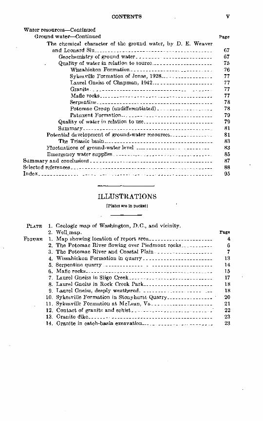
ILLUSTRATIONS[Plates are in pocket]
PLATE 1. Geologic map of Washington, D.C., and vicinity.2. WelLmap.
FIGURE 1. Map showing location of report area------------2. The Potomac River flowing over Piedmont rocks.3. The Potomac River and Coastal Plain.-.__-_-._4. Wissahickon Formation in quarry-______---_--_5. Serpentine quarry__-_-_______-____----_--6. Mafic rocks.---_____-_.____-_-_____-___..____7. Laurel Gneiss in Sligo Creek_--___-_._-_-__--__8. Laurel Gneiss in Rock Creek Park._____________9. Laurel Gneiss, deeply weathered.__-_-----------
10. Sykesville Formation in Stonyhurst Quarry..---.11. Sykesville Formation at McLean, Va_ __ ._-____12. Contact of granite and schist.-----------------13. Granite dike.---------_---___-----_._-_______14. Granite in catch-basin excavation ____________
Page 467
1314151718182021222323

VI CONTENTS
PageFIGURE 15. Kensington Granite Gneiss^ -____------___._____-_---__-- 24
16. Aplite dikes at Glen Echo. ---_--________________.__._- 2617. Fractured quartz vein_-_--____--.__._________-__--__-__- 2718. Folding in Wissahickon Formation______________________ 2819. Patuxent Formation in sandpit -__--__---________---___ - 3020. Bryn Mawr(?) Gravel near Tysons Crossroads.__-._------- 3721. Gravel pit at Lincolnia, Va_...__.....-..__-....._.--_--- 3922. Colluvium overlying schist---------.------------..------- 4023. Silver Spring-.-._------------___--__---______----- 4224. Takoma Spring_____--__________________________----. 4425. Zones of subsurface water-__--_-----___----______------- 5026. Diagram, hydrologic principles._--___--___________--_---- 5227. Diagram of well types..-__-_-_-_-___--_____-___._------- 5828. Graph showing chemical constituents of ground water------- 7629. Month-end water levels-___.___--__-________.__.__-----_- 86
TABLES
Page TABLE 1. Piedmont formations and their water-bearing properties,
Washington, D.C., and vicinity-.______________________ 612. Coastal Plain formations and their water-bearing properties,
Washington, D.C., and vicinity. -.-------_____--------- 623. Depth and yield of drilled wells in the Piedmont by geologic
units ________________________________________________ 644. Yield of drilled wells in the Piedmont by depth intervals ______ 645. Relation of yield of drilled wells in the Piedmont to depth of
weathering._________________________________________ 656. Depth, casing, and yield of drilled wells in the Piedmont by
topographic position __________________________________ 667. Dug and bored wells in the Piedmont and Coastal Plain
relation of depth of well and water-level to topographic position ______-___-------________-_-_--_______--_---_ 66
8. Yield of drilled wells in the Coastal Plain___..._______ 669. Chemical analyses of ground water in Washington, D.C., and
vicinity __-_-____---_______.-____-___________--__---- 6810. Summary of analyses of ground water in Washington, D.C.,
and vicinity__-___-__--___-------.__-_-.___.--------- 7411. Public Health Service standards_-----___---__--._---.-_ -- 7912. Ground-water levels in observation wells. --_---__--------- 84
GEOLOGY AND GROUND-WATER RESOURCES OF WASHINGTON, D.C., AND VICINITY
By PATJL M. JOHNSTON
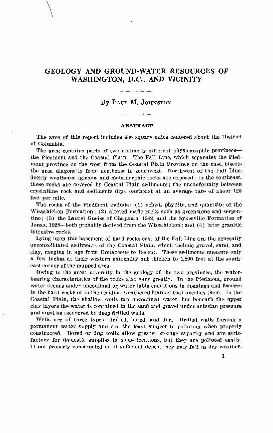
ABSTRACT
The area of this report includes 436 square miles centered about the District of Columbia.
The area contains parts of two distinctly different physiographic provinces the Piedmont and the Coastal Plain. The Fall Line, which separates the Pied mont province on the west from the Coastal Plain Province on the east, bisects the area diagonally from northeast to southwest. Northwest of the Fall Line, deeply weathered igneous and metamorphic rocks are exposed; to the southeast, these rocks are covered by Coastal Plain sediments; the unconformity between crystalline rock and sediments dips southeast at an average rate of about 125 feet per mile.
The rocks of the Piedmont include: (1) schist, phyllite, and quartzite of the Wissahickon Formation; (2) altered mafic rocks such as greenstone and serpen tine; (3) the Laurel Gneiss of Chapman, 1942, and the Sykesville Formation of Jonas, 1928 both probably derived from the Wissahiekon ; and (4) later granitic intrusive rocks.
Lying upon this basement of hard rocks east of the Fall Line are the generally unconsolidated sediments of the Coastal Plain, which include gravel, sand, and clay, ranging in age from Cretaceous to Recent. These sediments measure only a few inches at their western extremity but thicken to 1,800 feet at the south east corner of the mapped area.
Owing to the great diversity in the geology of the two provinces, the water bearing characteristics of the rocks also vary greatly. In the Piedmont, ground water occurs under unconfined or water-table conditions in openings and fissures in the hard rocks or in the residual weathered blanket that overlies them. In the Coastal Plain, the shallow wells tap unconfined water, but beneath the upper clay layers the water is contained in the sand and gravel under artesian pressure and must be recovered by deep drilled wells.
Wells are of three types drilled, bored, and dug. Drilled wells furnish a permanent water supply and are the least subject to pollution when properly constructed. Bored or dug wells allow greater storage capacity and are satis>- factory for domestic supplies in some locations, but they are polluted easily. If not properly constructed or of sufficient depth, they may fail in dry weather.

2 GEOLOGY, GROUND WATER, WASHINGTON, P.C.
Ground-water supplies for domestic use, 5 to 10 gpm (gallons per minute), are obtainable in most places. In the Piedmont, recorded yields in drilled wells range from 0.2 to 212 gpm. In the Coastal Plain, wells yield from 1 to 800 gpm.
The quality of the ground water in the report area is generally satisfactory for domestic, industrial, and irrigation use. High iron content and corrosiveness are troublesome in places. The water is soft to moderately hard 2 to 175 ppm (parts per million). Water in the Piedmont province is- dominantly the calcium and bicarbonate type; in the Coastal Plain most water is of calcium-magnesium bicarbonate type.
In the Piedmont, careful location of wells with respect to the geology (rock type and structure) and to topography usually results in higher yields and may mean the difference between success and failure. In the Coastal Plain, drilled artesian wells are not affected by topography, but the yield obtained depends upon the penetration of a water-bearing sand or gravel bed at sufficient depth.
The early settlers obtained water from the springs and streams, and later from dug wells. After Washington was established as the Capital in 1800, water was obtained from public and privately owned wells. Water was piped from some of the springs to government buildings and to private homes and business houses. In 1863 a diversion dam was completed in the Potomac above Great Falls and a conduit was built into the city to furnish a public water supply. This system with modifications has been in use ever since. A new diversion dam and pumping station at Little Falls was put into service in the summer of 1959.
In 1961 the total pumpage from Coastal Plain aquifers in the report area was estimated to be about 15 mgd (million gallons per day). An estimate of the withdrawal from Piedmont aquifers cannot be made from the information available.
Observations of ground-water levels in the Washington area indicate no sus tained downward trend, and at the present rate of development, there is no evidence that the area's ground-water resources will be depleted in the near future.
The present practice of using a major surface-water supply supplemented by ground water is also the best plan for the future. Certainly the area's needs cannot be met by ground water alone, but wells are capable of supplying a sub stantial amount of water which otherwise would not be us«d. Furthermore, many parts of the area are not served by city water and will continue to depend upon ground-water supplies.
INTRODUCTION
PURPOSE AND SCOPE OF THE INVESTIGATION
Published ground-water data pertaining to the District of Columbia and adjacent parts of Virginia are outdated or are out of print; the most recent information (1954) concerning Maryland is published in the reports of that State. Therefore a single report discussing the ground-water resources of the metropolitan area has been needed for some time.
Since World War II, the suburban area surrounding Washington, D.C., in common with most other metropolitan areas in this country, has been expanding rapidly. The movement of the population to the
INTRODUCTION 3
suburbs brings with it the demand for new homes; towns and villages in the suburban area are overrunning their limits, and more-or-less isolated subdivisions are springing up in the intervening open coun try. All types of construction including schools, highways, and civil and military facilities and the establishment of new industry in the suburbs demand geologic information, including ground-water data, for additional water supplies. Many such developments are far from city waterlines; hence ground-water supplies must be furnished.
The base map used in this report is a reduction (scale 1: 62,500) of the Geological Survey map of Washington and vicinity, Md.-Va.-D.C. (1949) (1:31,680). The geology (pi. 1) is a composite of mapping done in Maryland and the District of Columbia by Cooke and Cloos (1951) ; in Maryland and the District of Columbia by Cloos and Cooke (1953); in the Coastal Plain of Virginia by Darton (1947) ; and in the Virginia Piedmont by the writer. The geologic mapping done in the Piedmont of Virginia in 1901 had become inadequate for cur rent needs; hence it was necessary to map the Virginia Piedmont area especially for this report.
During the course of the investigation 1,022 wells and springs were located for which physical data were collected. (See Johnston, 1961, tables 13-16.) Chemical analyses were made of 102 water samples. In areas where no wells could be located, subsurface data were supplied from foundation borings.
LOCATION OP THE AREA
The area discussed in this report includes that shown on the Geological Survey map of Washington and vicinity (1949). The area contains 436 square miles, of which almost 14 square miles is water surface. Political subdivisions included are: the District of Columbia; parts of Montgomery and Prince Georges Counties in Maryland; and all of Arlington County, Alexandria, and Falls Church, and parts of Fairfax County and the town of Vienna in Virginia (fig. 1).
PREVIOUS INVESTIGATIONS
The pioneer in the study of geology and ground water of the Wash ington area was the late N. H. Darton of the Geological Survey. Among Darton's publications are the "Atlas Folio of the Washington Area" (1901), in which he collaborated with G. H. Williams and

4 GEOLOGY, GROUND WATER, WASHINGTON, D.C.
Arthur Keith; "The Sedimentary Formations of Washington, D.C., and Vicinity" (1947); and "Configuration of the Bedrock Surface of the District of Columbia and Vicinity" (1950).
Between 1930 and 1950, well data in the area were collected by various Survey geologists, including G. H. Hall, A. C. Byers, V. C. Fishel, and F. H. Klaer.
In 1951 and 1952, J. H. Christensen, then a geologist with the Sur vey, collected additional ground-water information in the District of Columbia. Some of the data collected by him are included in the present report.
In 1938 a report on the ground-water resources of northern Virginia was prepared by R. C. Cady, Survey geologist, and published by the Virginia Geological Survey. A report on the geology and ground- water resources of Prince Georges County, Md., was prepared in 1952 with the cooperation of the Maryland Department of Geology, Mines and Water Resources by C. Wythe Cooke and Gerald Meyer, Survey geologists. A report on the ground-water resources of Montgomery County, Md., by R. J. Dingman and Gerald Meyer, also in cooperation with the State, was published in 1954. Both Maryland reports were published by the State.
02468 10 MILES
FIGURE 1. Map showing location of report area.

GEOGRAPHY 5
The sedimentary formations of Prince Georges and Montgomery Counties were mapped by C. Wythe Cooke, and the metamorphic and igneous rocks by Ernst Cloos, Johns Hopkins University; the maps were published by the State of Maryland in 1951 and 1953 respectively.
ACKNOWLEDGMENTS
Acknowledgment is made to Ernst Cloos of The Johns Hopkins University and to C. Wythe Cooke of the Geological Survey for the use of their geologic maps of the Piedmont and Coastal Plain in Mary land and the District of Columbia. The descriptions of the Coastal Plain deposits in Maryland and Virginia are largely from Cooke (1952) andDarton (1947), respectively.
Microscopic mineral determinations were made by R. R. Blanken- ship. Arthur R. Levy assisted in field and office in 1956-58, and Lee Plein and Arnold Boettcher were summer field assistants in 1954 and 1955, respectively. William Kephart and O. J. Coskery assisted dur ing the period 1957-59.
In the District and Virginia information on wells was obtained from the District of Columbia Division of Sanitation and from owners and well drillers, all of whom cooperated to the fullest extent. In Maryland, well data were obtained from E. G. Otton, District Geologist, U.S. Geological Survey, Baltimore, Md.
Information on population, agriculture, industry, and transporta tion was furnished by the Fairfax County Planning Commission, the City of Alexandria, the City of Falls Church, the Arlington County Planning office, the Maryland-National Capital Parks and Planning Commission, and the District of Columbia Board of Trade.
Information on climate was furnished by the U.S. Weather Bureau. Foundation test-boring logs were made available by the Raymond Concrete Pile Co. and their clients, by the consulting engineering firm of Howard, Needles, Tammen, and Bergendoff, the Virginia Depart ment of Highways, and others.
Acknowledgment is due R. L. Orndorff, Deputy Director of Sani tary Engineering, District of Columbia, and J. C. Smith, Chief, Water Supply Branch of the Army Corps of Engineers, who furnished in formation and assistance for the section on the history of water supply.
GEOGRAPHY
SURFACE FEATURES AND DRAINAGE
The Washington, D.C., area, as shown on the topographic map of Washington and vicinity (1949), straddles the Fall Line, the boundary separating the Piedmont physiographic province on the northwest from the Coastal Plain province on the southeast. The Piedmont province extends from Maine to Alabama; it is about 40 miles wide in

6 GEOLOGY, GROUND WATER, WASHINGTON, B.C.
this latitude. East of the Fall Line the hard rocks of the Piedmont are buried beneath the unconsolidated sand, gravel, and clay of the Coastal Plain.
The topography of the Washington area displays moderate relief. The highest point is near Tysons Crossroads in the Falls Church quadrangle altitude 518 feet and the lowest point is at sea level the surface of the Potomac at Chain Bridge and downstream. The greatest local relief is about 260 feet, upstream from Great Falls. North of the river the highest points are near Glen Hills (450 feet); Eockville, Glenmont, and Fairland (460 feet); and Wheaton (480 feet). South of the river the surface ranges from 518 feet near Tysons Crossroads to 30 feet in Hybla Valley south of Alexandria and to sea level in the Potomac River. The boundary between the Piedmont and the Coastal Plain shows no abrupt change of topography; the sediments feather out onto the Piedmont. A few detached outliers of the Coastal Plain sediments cap high ground in the central and west- central parts of the area.
The entire area is drained by the Potomac River (figs. 2 and 3) and its local tributaries, Anacostia River and Rock Creek in the north, and Difficult Run, Pimmit Run, Holmes Run, and Accotink Creek in in the south.
FIGURE 2. The Potomac River flowing over Piedmont rocks below Great Falls, looking upstream. Quartzlte and schist of the Wlssahlckon Formation exposed in river bluffs. River terrace deposits cap ridge on left.
GEOGRAPHY
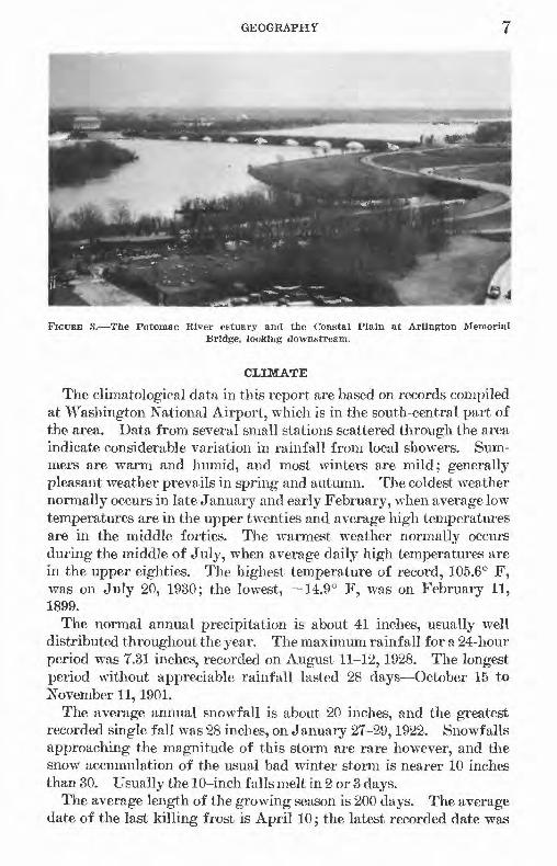
FIGUEB 3. The Potomac River estuary and the Coastal Plain at Arlington Memorial Bridge, looking downstream.
CLIMATE
The climatological data in this report are based on records compiled at Washington National Airport, which is in the south-central part of the area. Data from several small stations scattered through the area indicate considerable variation in rainfall from local showers. Sum mers are warm and humid, and most winters are mild; generally pleasant weather prevails in spring and autumn. The coldest weather normally occurs in late January and early February, when average low temperatures are in the upper twenties and average high temperatures are in the middle forties. The warmest weather normally occurs during the middle of July, when average daily high temperatures are in the upper eighties. The highest temperature of record, 105.6° F, was on July 20, 1930; the lowest, -14.9° F, was on February 11, 1899.
The normal annual precipitation is about 41 inches, usually well distributed throughout the year. The maximum rainfall for a 24-hour period was 7.31 inches, recorded on August 11-12,1928. The longest period without appreciable rainfall lasted 28 days October 15 to November 11,1901.
The average annual snowfall is about 20 inches, and the greatest recorded single fall was 28 inches, on January 27-29,1922. Snowfalls approaching the magnitude of this storm are rare however, and the snow accumulation of the usual bad winter storm is nearer 10 inches than 30. Usually the 10-inch falls melt in 2 or 3 days.
The average length of the growing season is 200 days. The average date of the last killing frost is April 10; the latest recorded date was

8 GEOLOGY, GROUND WATER, WASHINGTON, D.C.
May 12,1913. The average date of the first killing frost is October 28, and the earliest recorded date was October 2, 1899.
ECONOMIC DEVELOPMENT
The area discussed in this report comprises 436 square miles, of which 60 square miles lies within the District of Columbia, 216 square miles in Maryland, and 160 square miles in Virginia.
The population of this area, estimated as of January 1959, was 1,740,500 of which 770,000 were in the District of Columbia, 595,000 in Maryland, and 375,500 in Virginia.
Agriculture is rapidly disappearing as an occupation in this area. However, some livestock, dairy products, tobacco and field crops are produced in nearby Maryland and Virginia.
In the District of Columbia and surrounding area, industrial estab lishments produce food and food products, lumber and wood products, furniture and fixtures, printed materials, metal parts, machinery, in struments, chemicals, refrigerator cars, electronic equipment, and con crete products. Several electronic-research establishments and testing laboratories are located in the area.
The production of sand and gravel is by far the most important mineral industry in the area. Some building stone and crushed rock are obtained from the Sykesville Formation (Jonas, 1929) in the River Road Seven Locks Road area of Maryland. Crushed rock is produced from the serpentine southwest of Rockville. Bricks are made from the Arundel (?) Clay, which, in former days produced some iron.
Before 1900 gold was obtained in nearby Montgomery County from placer deposits in the streambeds and from shafts sunk in the rock. Emmons (1890) reports a mine known as Montgomery mine in the vicinity of Great Falls on upper Rock Run. This mine was reac tivated in 1890, and it was reported that $8,000 in gold had been taken from the streambed.
The Allerton-Ream property on the east bank of the Potomac about three-fourths of a mile above Great Falls was worked by open cut in contorted mica schist. At the Harrison group gold mines on Rock Run, 1 mile north of Conduit road, eight or more veins (quartz ?) were exposed where the stream cuts across the strike of the rock. Huddleston farm was the site of a gold mine on the east fork of Cabin John Creek about 8 miles northwest of Washington (Emmons, 1890).
Southwest of the intersection of Falls Road and McArthur Boule vard, a deep shaft and remains of mine buildings can still be seen.
No gold is mined in this area at present, but reportedly it can be panned in small amounts from some of the streams.
GEOLOGY, GROUND WATER, WASHINGTON, D.C. 9
GEOLOGY
Washington, D.C., is in an area of extremely diverse geology. The Fall Line, or Fall Zone, passes ronghly from Fort Belvoir on the south through Roosevelt Island and the District of Columbia to Silver Spring and Fairland on the north, separating the Piedmont on the northwest from the Coastal Plain on the southeast. The Piedmont is made up of generally hard igneous rocks and metamorphic rocks derived from sedimentary and older igneous rocks 'by dynamic and contact metamorphism. (See pi. 1).
The area has never been glaciated; hence, uplands and hillsides are covered by deep residual soils except where certain highly resistant rocks crop out. Only in the river and major stream valleys of the Piedmont, where the thick residual cover has been removed by running water, can the nature of most of these rocks be seen.
At the Fall Line the hard rocks of the Piedmont pass under the sediments clay, sand, and gravel of the Coastal Plain. The bedrock surface dips to the southeast at an average rate of about 125 feet per mile.. The rocks of the Piedmont include: (1) schist, phyllite, and quart- zite of the Wissahickon Formation; (2) altered mafic and ultramafic rocks such as greenstone and serpentine; (3) the Laurel Gneiss of Chapman, 1942, which was apparently derived from the Wissahickon by hydrothermal alteration; (4) the Sykesville Formation of Jonas, 1929, which consists of highly altered remnants of the Wissahickon Formation together With intrusive biotite granite, quartz diorite (ton- alite), and associated rocks; and (5) later granitic intrusive rocks such as the Bear Island Granodiorite of Cloos, 1953 (Cloos and Cooke, 1953), in Maryland, and similar granitic rocks in Virginia. In short, the rocks underlying the Piedmont of the Washington area are com posed of the Wissahickon Formation in various stages of alteration plus associated f elsic and mafic rocks.
East of the Fall Line, but including isolated outliers capping nearby uplands on the west, the sediments of the Coastal Plain lie upon the bedrock surface. These sedimentary rocks (generally unconsolidated) form a southe,astward-thickening wedge in which the beds, from bottom to top, dip successively less than the bedrock surface (Darton, 1947), and whose ages range from Cretaceous at the bottom through Pleistocene and Recent at the top.
This is a greatly simplified version of the structure of the Coastal Plain. The Coastal Plain deposits in the Washington area were laid down under variable conditions in subaerial and near-shoreline en vironments, and the beds are not continuous over long distances.

10 GEOLOGY, GROUND WATER, WASHINGTON, D.C.
REGIONAL GEOLOGIC HISTORY
The rocks of the Washington area and adjacent regions include representatives of the three broad groups sedimentary, metamorphic, and igneous. The sedimentary rocks include the Cretaceous and younger sand, gravel, and clay of the Coastal Plain and stream- channel and colluvial deposits of Kecent age. Sedimentary rocks of Triassic age lie about 12 miles west of the District of Columbia, be yond the limits of the map.
The sedimentary rocks are underlain by metamorphic rocks derived from much older sedimentary and igneous rocks. Intermediate in age between the sedimentary rocks and these older metamorphic rocks are igneous intrusive rocks which include mafic (basaltic) and felsic (granitic) types.
The metamorphic rocks, which underlie about half the area, include the Wissahickon Formation and Sykesville Formation of Jonas, 1928, and the Laurel Gneiss of Chapman, 1942, together with serpen tine and greenstone which are altered intrusives or are interbedded in the Wissahickon Formation. Altered granitic intrusive rocks also are included among the metamorphic rocks. These rocks have had a very long and complicated history, and their ages have been the sub ject .of discussion for many years.
Later intrusive rocks of the Piedmont are the Bear Island Granodi- orite and Kensington Granite Gneiss of Cloos (Cloos and Cooke, 1953 ; Cooke and Cloos, 1951, respectively) in Maryland and their equiva lents in Virginia.
In most published literature dealing with the subject, the age of the Wissahickon is given as Precambrian. However, originally, ge ologists considered it to be of Cambrian and Ordovician age, a con clusion which seems to be strengthened by later work in Pennsylvania and Maryland (Miller, 1935; Mackin, 1935; Cloos and Hietanen, 1941; Scotford, 1951; and Whitaker, 1955). The lack of fossils in the Wis sahickon thus far has precluded absolute proof, but evidence points to the conclusion that the Wissahickon rocks are the metamorphic equiv alents of known Cambrian and Ordovician rocks farther west. The problem may in time be resolved by geochemical dating methods or diagnostic fossils may yet be discovered, but for the present the age is considered to be early Paleozoic (?).
The history of these rocks begins with the deposition of sediments in the sea at least 440 million years ago (Holmes, 1959). After con solidation, the rocks were raised above the sea and intruded by mafic magmas, which in some places reached the surface and resulted in volcanic activity. Much later, in late Paleozoic time, strong compres- sive forces, acting in a northwest or southeast direction buckled the

GEOLOGY 11
earth's crust and compressed the beds into tight folds. During and after this mountain-building activity, probably in late Paleozoic time (Cloos and Hershey, 1936), another series of intrusions took place, involving both felsic and mafic magmas which congealed at some depth below the surface, producing granite and gabbro. Lonsdale (1927, p. 39) mentions post-Cambrian and post-Ordovician granitic rocks in the Piedmont of Stafford and Prince William Counties, Va. Knopf and Jonas (1929a) described Paleozoic granite in Baltimore County, Md. Late Paleozoic pegmatite occurs in the Sykesville and Peters Creek Formations in Car roll County, Md. (Stose and Stose, 1946).
After the mountain-making activity, a long period of erosion re duced the ancient mountains nearly to base level before the region again sank beneath the sea. Sediments deposited upon the eroded surface in Triassic time were intruded by another series of mafic rocks (Triassic traprock or diabase). At the close of the Triassic, tilting and faulting took place and low mountains were formed, but the geologic record gives no evidence of further extensive folding in this area (Moore, 1933, p. 410).
During the Jurassic, this region probably remained above sea level ; no Jurassic sediments have been recognized. Erosion reduced the region to a surface of low relief; eastward tilting brought its eastern part beneath the sea, and stream cutting increased in the western part. Cretaceous and younger sediments in the Coastal Plain were deposited in and near the sea, which during Pleistocene time fell and rose with the advance and retreat of the ice (Cooke, 1952, p. 42-45). However, the continental ice sheet never advanced south of central Pennsylvania and northern New Jersey.
Coastal Plain sediments once extended farther west than they do now, but they have been removed by erosion.
Relatively minor faulting has taken place since Cretaceous time, as shown by faulting of the Wissahickon over gravel of Cretaceous age in the District of Columbia (Carr, 1950, p. 21) and elsewhere (White, W. A., 1952).
GEOLOGIC FORMATIONS
THE PIEDMONT
LOWER PALEOZOIC (?) BOCKS
WISSAHICKON FORMATION
The Wissahickon Formation of early Paleozoic(?) age was named originally by Bascom (1905), from exposures along Wissahickon Creek in Philadelphia. Similar rocks have been mapped as Wissa hickon from Pennsylvania to Alabama. The formation passes beneath
711-570 O 64 2
12 GEOLOGY, GROUND WATER, WASHINGTON, D.C.
the Coastal Plain on the north and south and in some places on the east. West of Washington it grades into other formations or is con- ' cealed beneath rocks of Triassic age. It occupies roughly most of the map area northwest of the northwest District of Columbia line extended.
The geologic map of Virginia (Stose, 1928) shows the Virginia part of the Washington area to be occupied by Wissahickon schist, intruded by granite on its southeast side, "largely biotite granite and quartz monzonite; some muscovite granite and pegmatite," and by quartz diorite on the northeast.
In the Washington area the Wissahickon is composed of quartz- mica schist, phyllite, and quartzite. The schist grades into finer grained phyllite and into quartzite. Quartz (30 to 60 percent) forms the bulk of the schist, which contains abundant sericite (15 to 45 percent) and variable amounts of biotite and chlorite. In some places the biotite or chlorite content is as high as 30 percent; in many places traces of clinozoisite-epidote are present, and two samples contained 10 to 20 percent of this mineral. Minor accessory minerals are garnet (almost everywhere), ilmeiiite, magnetite, sphene, and tourmaline.
The color of fresh, unweathered schist and phyllite is various shades of gray, bluish gray, or greenish gray. These rocks commonly exhibit a silvery luster on cleavage surfaces owing to the abundant sericite.
The quartzite in the Wissahickon is massive to somewhat schistose, very fine to coarse, and contains 60 percent or more of quartz. Some of the quartzite contains appreciable amounts of biotite, 5 to 20 per cent, and (or) chlorite, 5 to 10 percent. The fresh rock is generally dark gray, but the color ranges from nearly white to very dark, almost black. The darker, finer grained quartzite in hand samples resembles ferromagnesian rock and may be mistaken for an intrusive. One specimen of a related dark fine-grained rock from the circumferential- highway crossing, west of Annandale, contained 40 percent quartz, 40 percent biotite, and 15 percent clinozoisite-epidote but could scarcely be classified as a quartzite.
The schist and phyllite of the Wissahickon weather readily, produc ing a buff-colored, reddish, yellow, or drab micaceous clayey, silty soil; the quartzite, which is somewhat more resistant, weathers to a fine silty to medium-grained sandy soil, similarly colored.
The schist tends to split into laminae along the planes of schistosity; the quartzite does also to some extent, but the more massive quartzite breaks into blocks along three major joint sets: one nearly parallel to the schistosity, one nearly at right angles, both steeply inclined, and third nearly horizontal or only slightly inclined. The joint system in the quartzite also is common to the schist.
GEOLOGY 13
In Maryland, Cloos and Cooke (1953) subdivided the Wissahickon Formation into two facies the Wissahickon albite-chlorite facies on the west and the Wissahickon oligoclase-mica facies on the east. No similar subdivision has been made in Virginia.
Fresh exposures of the Wissahickon Formation can be seen along both sides of the Potomac River between Plummer Island and Great Falls. In Maryland, typical weathered exposures can be observed west of Rock Creek just south of East-West Highway; in Virginia, along Dulany Drive in Elmwood Estates, which is off Old Dominion Drive west of McLean; in contact with chlorite schist on Kirby Road near Westmoreland Road; and along U.S. Highway 29-211 west of Merrifield.
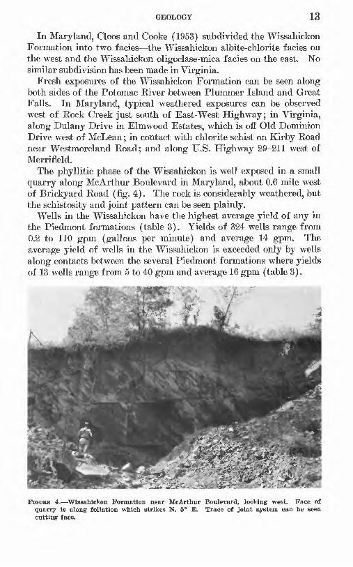
The phyllitic phase of the Wissahickon is well exposed in a small quarry along McArthur Boulevard in Maryland, about 0.6 mile west of Brickyard Road (fig. 4). The rock is considerably weathered, but the schistosity and joint pattern can be seen plainly.
Wells in the Wissahickon have the highest average yield of any in the Piedmont formations (table 3). Yields of 324 wells range from 0.2 to 110 gpm (gallons per minute) and average 14 gpm. The average yield of wells in the Wissahickon is exceeded only by wells along contacts between the several Piedmont formations where yields of 13 wells range from 5 to 40 gpm and average 16 gpm (table 3).
K
FIGUBE 4. Wissahickon Formation near McArthur Boulevard, looking west. Face of quarry is along foliation which strikes N. 5° E. Trace of joint system can be seen cutting face.

14 GEOLOGY, GROUND WATER, WASHINGTON, D.C.
BOCKS OF UNKNOWN AGE
SERPENTINE
Serpentine occurs in various places in the Piedmont in large and small bodies, but only one body has been recognized in the mapped area. It is located in the northwest corner of the map (pi. 1), west of Rockville, and extends about 2^ miles southwestward in a body about a mile wide. The principal rock, as exposed in the quarry of the Rockville Crushed Stone Co., is gray to dark-green or black serpen tine cut by fine veinlets of calcite. In some places green pyroxene, probably diopside, occurs; garnet is an accessory mineral.
Schistosity is not prominent, in the serpentine. Instead, the rock tends to break along curved surfaces (fig. 5).
Wells in serpentine have the lowest yield of any in the Piedmont formations. The 5 wells sampled yield from 3 to 10 gpm and average 6gpm. (See table 3.)
MAFIC ROCKS
The group of allied rocks designated as mafic rocks in this report occurs in two large bodies and many small ones in the Washington area. One large body about 1% miles wide is northeast of Rockville; the second begins about 3% miles southeast, of Rockville as a sliver between the two facies of the Wissahickon and widens southward to ward the Potomac River. Near the crossing of River Road, it splits
^ *> J£ *** j-fi- £r . rrL ,1 -* ~ -
FIGURE 5. Serpentine In the quarry of the Rockville Crushed Stone Co.
GEOLOGY 15
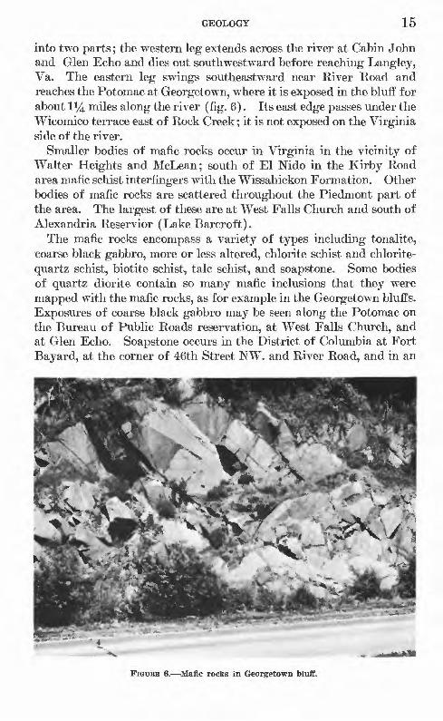
into two parts; the western leg extends across the river at Cabin John and Glen Echo and dies out south-westward, before reaching Langley, Va. The eastern leg swings southeastward near River Road and reaches the Potomac at Georgetown, where it is exposed in the bluff for about li/4 miles along the river (fig. 6). Its east edge passes under the Wicomico terrace east of Rock Creek; it is not exposed on the Virginia side of the river.
Smaller bodies of mafic rocks occur in Virginia in the vicinity of Walter Heights and McLean; south of El Nido in the Kirby Road area mafic schist interfingers with the Wissahickon Formation. Other bodies of mafic rocks are scattered throughout the Piedmont part of the area. The largest of these are at West Falls Church and south of Alexandria Reservior (Lake Barcroft).
The mafic rocks encompass a variety of types including tonalite, coarse black gabbro, more or less altered, chlorite schist and chlorite- quartz schist, biotite schist, talc schist, and soapstone. Some bodies of quartz diorite contain so many mafic inclusions that they were mapped with the mafic rocks, as for example in the Georgetown bluffs. Exposures of coarse black gabbro may be seen along the Potomac on the Bureau of Public Roads reservation, at West Falls Church, and at Glen Echo. Soapstone occurs in the District of Columbia at Fort Bayard, at the corner of 46th Street NW. and River Road, and in an
FIGUKE 6. Mafic rocks in Georgetown bluff.
16 GEOLOGY, GROUND WATER, WASHINGTON, D.C.
abandoned quarry on the river bluff north of the main building on the Bureau of Public Roads reservation at Langley, Va.
Biotite schist, chlorite schist, and hornblende schist bodies formed by metamorphism of flows or intrusives of relatively small size, too small to show on the map, may be seen in most of the bedrock forma tions of the Washington area except in the younger granite.
Most of the rocks in the mafic complex contain clinozoisite-epidote in varying amounts; the range is 5 to 60 percent. Abundant amphi- bole, particularly hornblende, ranges from 10 to 50 percent. The quartz component is uncommonly high for this type of rock, amount ing to as much as 45 percent in some specimens.
In most places these mafic rocks weather to a dark-brown or reddish soil, but more rarely a pale-green soil may result. Weathering pro ceeds to various depths; schist with little quartz weathers more readily than the more massive or siliceous types. However, the metagabbro behind the shopping center at West Falls Church, although containing little or no quartz, is comparatively fresh near the surface.
Average yield of wells in mafic rocks is about equal to the average of all wells in the Piedmont (table 3). Twenty-five wells sampled yield from 3 to 45 gpm and average 13 gpm. This agrees with 13 gpm in Montgomery County (Dingman and Meyer, 1954) but is much greater than the average for Fairfax quadrangle, where mafic rocks (greenstone) average 6 gpm (Johnston, 1962c). This is not surpris ing, considering the many rock types included in the unit and the relative degree of fracturing from one locality to another.
LAUREL GNEISS OF CHAPMAN, 1942
The Laurel Gneiss was originally named the Laural migmatite by Cloos and Broedel (1940) after its type locality near the town of Laurel in Prince Georges County, Md. Chapman (1942), in a study of the Laurel at its type locality, concluded that it was derived from the Wissahickon "under conditions of stress, high temperature and abundant water." He therefore suggested that the nongenetic name of gneiss be assigned to the formation; this is the name used on the geologic map of Montgomery County (Cloos, in Cloos and Cooke, 1953).
The Laurel Gneiss enters the area east of Fairland, Montgomery County, and trends southwestward, its west side grading into the Wissahickon, its east side concealed beneath the Coastal Plain. On the south it is truncated by the Wissahickon along Rock Creek near Piney Branch. The Laurel could not be traced in Virginia, but it may make up part of the area mapped as Sykesville south of the Potomac.
In outcrop the Laurel Gneiss has much the same appearance as the Sykesville, for the two formations weather similarly (fig. 7). Fresh

GEOLOGY 17
Laurel Gneiss generally has a lighter color and a more uniform grain than the Sykesville. At the type locality, Chapman (1942) reported only traces of chlorite in the Laurel. However, at the southern ex tremity of the formation in Rock Creek Park (fig. 8) the rock contains as much as 10 percent of chlorite.
At four scattered localities in and near the District the rock types in the Laurel are muscovite-biotite-chlorite-quartz schist, biotite-epi- dote-quartz schist, and muscovite-biotite-quartz gneiss.
In the weathered exposure at Winchester-Takoma Apartments in Takoma Park, Md., the original bedding of the Laurel Gneiss can be plainly seen (fig. 9).
Average yield of wells in the Laurel Gneiss is below the average for aquifers in the Piedmont. The yields of 15 wells range from 0.8 to 30 gpm and average 10 gpm.
SYKESVIIiE FORMATION OF JONAB, 1928
The Sykesville Formation was first named the Sykesville granite by Jonas and shown on the Carroll County, Md., geologic map (1928) as schistose biotite-quartz monzonite. The formation was later de scribed in detail by Stose and Stose (1946, p. 91-93). On the Mont gomery County geologic map (Cloos and Cooke, 1953), the designation Sykesville formation is used, and it is described as "granitic-looking schistose rock with numerous inclusions, quartz pebbles, garnets, grading into schist east and westward. Probably granitized schist."
FIGURE 7. Laurel Gneiss of Chapman. 1942. along Sligo Creek near Maple Avenue in Takoma Park. Inclusions In relief on weathered surface.

18 GEOLOGY, GROUND WATER, WASHINGTON, D.C.
FIGURE 8. Laurel Gneiss of Chapman, 1942, at Piney Branch and Beach Drive in Eock Creek Park, showing structure. Handle of hammer leans against foliation plane.
FIGURE 9. Laurel Gneiss of Chapman, 1942, deeply weathered, near Winchester-Takoma Apartments, Maple Avenue near Sligo Creek, Takoma Park.

GEOLOGY 19
In Carroll County the formation is said to be intrusive in the Peters Creek Formation (Stose and Stose, 1946, p. 92). Its extension south across Howard County lies between the Peters Creek Formation on the east and the Wissahickon on the west. The formation is 2% to 3y2 miles wide in northern Montgomery County, where it lies between the two facies of the Wissahickon Formation. This body enters the Wash ington area east of Rockville, where it is a little more than a mile wide. It pinches out about 2 miles farther south near the Baltimore and Ohio Railroad. Lenticular bodies aggregating a maximum width of about a mile in the Seven Locks Road area cross the Potomac be tween Cabin John and Carderock. These bodies, which are entirely enclosed within the Wissahickon Formation, merge south of the river, widen and appear to plunge beneath the Wissahickon between Lewins- ville and Brilyn Park. In this area the deep \vells at Pimmit Hills pass through the Wissahickon into the Sykesville beneath. A smaller lenticular body of Sykesville rocks extends across the river from Montgomery County near Offut and Hermit Islands, splits into two sections, and apparently dies out near Leesburg Road. A somewhat larger lenticular body about half a mile wide and 2y2 miles long occurs in the vicinity of Garrett Park, north of Bethesda, Md. The major body of Sykesville rocks in the Washington area extends from River Road between Glen Echo Heights and Ken wood and across the river between High Island and the Three Sisters. It fronts along the river for more than 4 miles before passing under the Coastal Plain sedi ments at its east margin. In Virginia its west boundary passes through Chesterbrook, Stafford Hills, East Falls Church and west of Seven Corners, east of Masonville and west of Annandale, where it passes with a gradational contact into the granite on the south. Its east boundary is concealed beneath the Coastal Plain.
In the Washington area, the Sykesville Formation appears to be a modified facies of the Wissahickon, which, before intrusion of the Sykesville granite, contained, along with schist and quartzite, a large component of mafic rocks, probably both intrusive rocks and inter- bedded flows. Granitic magmas were intruded into the Wissahickon and the Peters Creek farther north. The resulting intrusive rocks include quartz diorite, biotite granite, granodiorite, and quartz mon- zonite. These granitic rocks are very dark gray and contain inclusions of dark gray to black biotite schist or chlorite-epidote-quartz schist, sericite-quartz schist, and quartz fragments. It may be that the orig inal magma was of felsic composition but because of assimilation of ferro-magnesian rocks, took on a darker, mafic aspect. Included in the Sykesville Formation are muscovite or sericite-biotite-quartz schist and gneiss, quartzite, epidote quartzite, and muscovite-biotite
20 GEOLOGY, GROUND WATER, WASHINGTON, D.C.
quartzite. Eocks of the Sykesville Formation, despite their dark color, are highly quartzose. Excluding the quartzite, which contains at least 60 percent quartz, most of the rocks are estimated to contain 35 to 60 percent quartz. Feldspar in appreciable quantity 15 to 35 percent is found only in the intrusive rocks. Little or no feldspar is present in the schist, but sericite or muscovite content ranges from 15 to 35 percent. Biotite is almost universally present and ranges from 8 to 20 percent. Much of it is chloritized. Clinozoisite-epidote as much as 20 percent is found in some of the rocks but is much more widely distributed in the mafic rocks.
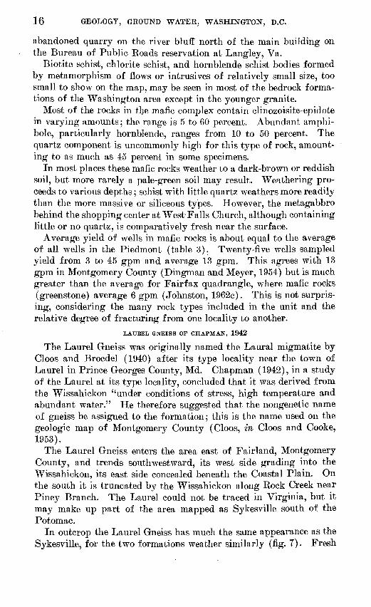
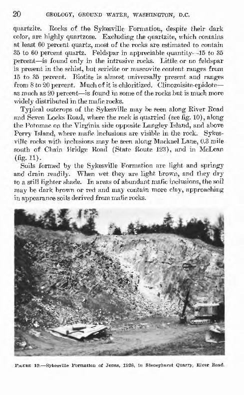
Typical outcrops of the Sykesville may be seen along Eiver Road and Seven Locks Road, where the rock is quarried (see fig. 10), along the Potomac on the Virginia side opposite Langley Island, and above Perry Island, where mafic inclusions are visible in the rock. Sykes ville rocks with inclusions may be seen along Macknel Lane, 0.3 mile south of Chain Bridge Road (State Route 123), and in McLean (fig. 11).
Soils formed by the Sykesville Formation are light and springy and drain readily. When wet they are light brown, and they dry to a still lighter shade. In areas of abundant mafic inclusions, the soil may be dark brown or red and may contain more clay, approaching in appearance soils derived from mafic rocks.
.** "
FIGURE 10. Sykesville Formation of Jonas, 1928, in Stoneyhurst Quarry, River Road.

GEOLOGY 21
Yields of wells in the Sykesville Formation average slightly less than those in the mafic rocks; an average of 12 gpm was obtained from 142 wells in the Washington area. Yields range from 2 to 100 gpm.
OBANITIC KOCKS
Granitic rocks are widely distributed; they range from large linear or irregular bodies 6 to 10 square miles in area to smaller bodies of only a few square feet. Granite and aplite dikes as much as several feet wide can be seen in many places.
The composition of the granitic rocks is variable. Included are biotite granite, muscovite granite, and biotite-muscovite granite; granodiorite; quartz monzonite; and quartz diorite (tonalite). Some of these rocks have been subjected to intense shearing, whereas others appear undistorted. Much of the rock is altered; the feldspars have been converted to sericite or clinozoisite-epidote. Most of the granitic rocks are highly siliceous; quartz content ranges from '20 to 60 percent.
The larger granitic bodies generally display gradational contacts with the surrounding schist, and remnants of schist are embedded in the granite at many places. Examples can be seen along the Southern Railway west of Springfield Station and along U.S. Highway 29-211 west of Falls Church. A large body of schist more than 3 miles long embedded in the granite extends from the vicinity of Calamo Branch, southwest of Springfield, westward into the Fairfax quadrangle. The
FIGUKE 11. Sykesville Formation of Jonas, 1928, showing Inclusions, McLean, Va.

22 GEOLOGY, GROUND WATER, WASHINGTON, B.C.
contact of the granite with this body of schist formerly could be seen along the telephone line south of Keene Mill Road (fig. 12). A section across the contact from north to south at this place is as follows:
Rock type
Granite ________Schist __ _ Granite ______Schist _________Quartz, crushed- Granite ________Schist _________
Feet
34
1526
The individual contacts are sharp and distinct, but the schist, which here is phyllitic, is highly distorted and schistosity does not follow the regional pattern. This exposure was destroyed about 1960 during construction of a small dam on a tributary of Accotink Creek.
Construction of the George Washington Parkway north of Chain Bridge Road exposed a white granite dike 100 feet wide, which crossed the parkway grade nearly at right angles (fig. 13). This dike is con cordant with the schistosity of the enclosing Sykesville schist. Little evidence of contact metamorphism was observed, but the schist was highly sheared for a few inches on each side of the dike, suggesting that there had been some movement after emplacement.
FIGURE 12. Contact of granite and scliist along telephone line south of Keene Mill Road.

GEOLOGY 23
Farther north along the parkway (fig. 14), a body of similar granite has been intruded along a slightly inclined joint as well as along the schistosity.
FIGURE 13. Granite dike 100 feet wide, Intrusive In Sykesvllle Formation of Jonas, 1928, along George Washington Parkway north of Chain Bridge Road.
FIGURE 14. Granite in catch-basin excavation, George Washington Parkway north ofChain Bridge Road.

24 GEOLOGY, GROUND WATER, WASHINGTON, D.C.
The granitic rocks appear to belong to at least three separate cycles of intrusion. The older, light-colored granitic rocks, which intruded the Wissahickon before folding (also the Sykesville and probably the Laurel), have been metamorphosed to schist and gneiss; the feldspars have been altered to sericite and much of the biotite to chlorite.
In the second cycle, probably during and immediately after the folding of the sediments, the biotite granite and its metamorphic equivalent (clinozoisite-epidote-quartz rock) were emplaced. Some of the granite is schistose, but some shows only slight distortion. To this cycle belong the Kensington Granite Gneiss of Cloos (Cooke and Cloos, 1951), the granite along Turkey Run in Virginia, and possibly the larger bodies of granite at Falls Church and to the south.
The body of granite shown on the southwest corner of the geologic map (pi. 1) is contiguous with the Occoquan Granite named by Lons- dale (1927, p. 45-48). Lonsdale placed his Occoquan in the Pre- cambrian and Cambrian range, although he stated that there was some evidence that it intruded the Quantico Slate (Ordovician).
A good example of the Kensington Granite Gneiss may be seen on Broad Branch in Rock Creek Park (fig. 15), just above a gradational contact with the Wissahickon.
The Bear Island Granodiorite of Cloos (Cloos and Cooke, 1953), which may represent the third cycle of intrusion, is exposed in an abandoned quarry along the Baltimore & Ohio Railroad just south of River Road.
FIGURE 15. Kensington Granite Gneiss of Ooos, 1951, in Broad Branch, half a mile abovemouth, in Rock Creek Park.

GEOLOGY 25
Altered quartz diorite with black inclusions is well exposed on the hilltop south of Tripps Bun, between Annadale Road and Sleepy Hollow Road. The rock in this exposure differs considerably in com position from that in the abandoned Falls Church quarry, which is only about 2y2 miles north.
The Tripps Run rock contains about 40 percent quartz and 30 per cent plagioclase, about half of which has been altered to clinozoisite- epidote. The rock contains abundant biotite and minor amounts of muscovite, and the mafic inclusions appear to be similar to those in the intrusives in the Sykesville.
In the Falls Church quarry pink and white granite contains 40 to 50 percent quartz, 30 to 40 percent orthoclase, and small amounts of plagioclase. Some sericite has formed. Granite from the Fort Belvoir quarry has a similar composition.
The granite varies considerably in its susceptibility to weathering. Soils developed on granite are generally light colored and sandy, but where the granite contain? many dark-colored inclusions or schist bodies, the soil tends to be reddish and clayey.
Wells tapping the undifferentiated granitic rocks of the Washing ton area have an average yield of 9 gpm, according to the 38 wells sampled (table 3). Yields range from 0.5 to 30 gpm. However, several wells drilled in the granite have been reported failures.
APLITE
Aplite bodies intrude the Piedmont rocks. The intruded aplite is in the form of dikes, sills, and irregular bodies, all of which range from a fraction of an inch to tens of feet across. Exposures are deeply weathered, except in stream channels, and resemble granulated sugar. Aplite bodies do not form prominences and may be concealed in places by movement of slope wash.
All the aplite bodies are white and are composed of quartz and feldspar. In some places tourmaline and white mica occur as acces sory minerals.
Examples of aplite dikes can be seen at many places in the Wash ington area. Good examples are at Glen Echo (Fig. 16), at Tysons Crossroads in back of the gasoline station on the northeast corner of Chain Bridge Road and State Route 7, along Kirby Road opposite Ivy Hill Drive, along Leesburg Road west of Madeira School, and at the Engineer Proving Grounds at Fort Belvoir.
The aplite bodies are not considered to be water-bearing formations because of their small areal extent. Several wells bottomed in aplite produced little or no water from it. The rock is generally relatively impermeable, and contacts with country rock are normally sealed.

26 GEOLOGY, GROUND WATER, WASHINGTON, D.C.
Drilling is very slow in these rocks; in one place not more than 1 foot per day could be drilled with a percussion-type rig.
QUARTZ VEINS
Quartz veins from a fraction of an inch to tens of feet across are found in all the Piedmont rocks of the Washington area. Some of the larger veins may be traced for half a mile or more; the smaller ones are only a few feet long.
Generally, the veins are highly distorted and in many places so badly shattered that small fragments no larger than a thumbnail litter the ground. Compression has crushed the quartz, and shear ing forces have pulled some of the veins apart so that they are no longer continuous. In some exposures a rude schistosity appears which parallels the regional trend of the enclosing rocks; in others schistosity is not apparent (fig. 17). Most of the quartz is white or slightly iron stained. In places it contains a few small black tourma line crystals or, more commonly, cubes of pyrite, some of which have been replaced by hematite. Fracture surfaces in many places show crusts of manganese oxide. Fragments of quartz weather out of the bedrock and accumulate on the surface, in time becoming corroded and heavily iron stained.
FIGURE 16. Apllte dikes In mafic rocks. Glen Echo, Md.
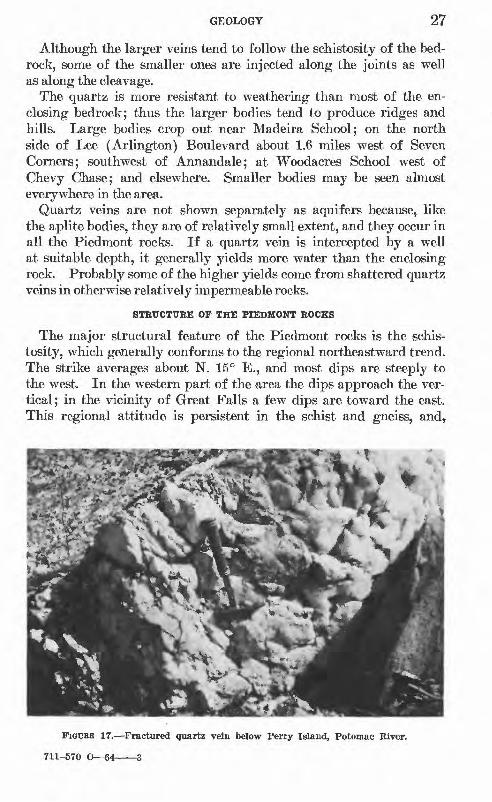
GEOLOGY 27
Although the larger veins tend to follow the schistosity of the bed rock, some of the smaller ones are injected along the joints as well as along the cleavage.
The quartz is more resistant to weathering than most of the en closing bedrock; thus the larger bodies tend to produce ridges and hills. Large bodies crop out near Madeira School; on the north side of Lee (Arlington) Boulevard about 1.6 miles west of Seven Corners; southwest of Annandale; at Woodacres School west of Chevy Chase; and elsewhere. Smaller bodies may be seen almost everywhere in the area.
Quartz veins are not shown separately as aquifers because, like the aplite bodies, they are of relatively small extent, and they occur in all the Piedmont rocks. If a quartz vein is intercepted by a well at suitable depth, it generally yields more water than the enclosing rock. Probably some of the higher yields come from shattered quartz veins in otherwise relatively impermeable rocks.
STRUCTURE OF THE PIEDMONT ROCKS
The major structural feature of the Piedmont rocks is the schis tosity, which generally conforms to the regional northeastward trend. The strike averages about N. 15° E., and most dips are steeply to the west. In the western part of the area the dips approach the ver tical ; in the vicinity of Great Falls a few dips are toward the east. This regional attitude is persistent in the schist and gneiss, and,
FICUEE 17. Fractured quartz vein below Perry Island, Potomac Kiver.
711-570 O 64 3
28 GEOLOGY, GROUND WATER, WASHINGTON, D.C.
although much less prominent in the younger intrusive rocks, most of the intrusives exhibit a foliation that is probably a primary struc ture imposed during emplacement in the enclosing schist (Cloos and Hershey, 1936).
The attitude of the schistosity varies locally, and the variation is most pronounced near intrusive contacts. This is most noticeable in the Annandale quadrangle, where the normal strike averages about N. 10° E. away from the contacts, but near the contacts with granitic rocks it averages N. 65° W.
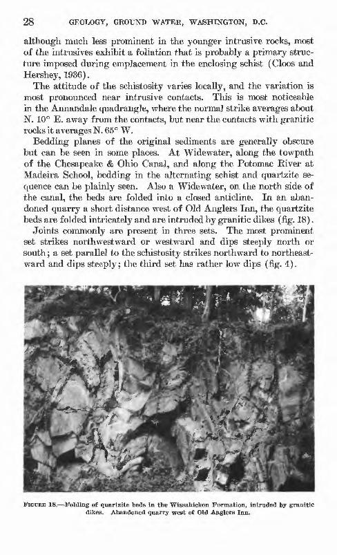
Bedding planes of the original sediments are generally obscure but can be seen in some places. At Widewater, along the towpath of the Chesapeake & Ohio Canal, and along the Potomac River at Madeira School, bedding in the alternating schist and quartzite se quence can be plainly seen. Also a Widewater, on the north side of the canal, the beds are folded into a closed anticline. In an aban doned quarry a short distance west of Old Anglers Inn, the quartzite beds are folded intricately and are intruded by granitic dikes (fig. 18).
Joints commonly are present in three sets. The most prominent set strikes northwestward or westward and dips steeply north or south; a set parallel to the schistosity strikes northward to northeast ward and dips steeply; the third set has rather low dips (fig. 4).
FIGURE 18, Folding of quartzite beds In the Wissahickon Formation, intruded by granitic dikes. Abandoned quarry west of Old Anglers Inn.
GEOLOGY 29
THE COASTAL PLAIN
LOWEB AND UPPEE CRETACEOITS SEEIES
POTOMAC OROITP
In Maryland the Potomac Group of Early and Late Cretaceous age is divided into three formations: (1) the Patuxent Formation (Lower Cretaceous), (2) the Arundel Clay, and (3) the Patapsco Formation (Upper Cretaceous). In the Maryland part of the report area, the Arundel and the Patapsco are not separated but are con sidered together. In the Virginia part, the Potomac Group is con sidered as a unit.
The Potomac Group is well exposed along the Richmond, Fred- ericksburg, & Potomac Railroad between Franconia and Bush Hill, Va. A composite section from core borings for the Washington Circumferential Highway in the vicinity of Mount Hebron Park is as follows:
TMcTcneas Depth Description (feet) (feet)
Gravel and soil_____________________ 3 3Silt, tan, and sand; trace of gravel________ 5 8Sand and silt, mottled; trace of mica________ --_ 5 13Silt, clayey, mottled_______________________-____ 8 21Sand, yellowish-brown__________ _____ 4 25Silt, clayey, green, and fine sand__ _____ __ 7 32Sand, yellowish-brown_____ __ ___ 6 38Sand, brown, and gravel with layers of gray clay 4 42Silt and clay, mottled ; trace of fine sand______ 25 67Sand, silty, multicolored_____________________-____ 22 89Top of bedrock_____________________________ 89
LOWEB CBETACEOUS SERIES
PATUXENT FORMATION
The Patuxent Formation was named by Clark (1897) from its type locality in the upper valleys of the Little and Big Patuxent Rivers. The following descriptions of the formation are in part adapted fromCooke (1952).
The formation contains large amounts of sand commonly mixed with variable amounts of kaolin and mica, gravel composed of large well-rounded polished pebbles, and lenses of varicolored or white massive clay.
According to Little (1917, p. 60), the known fauna of the Patuxent consists only of a Unio (a fresh-water mussel) and a fish. The flora includes ferns, horsetails, cycads, and conifers.
The Patuxent is the basal formation of the Coastal Plain; it lies directly upon the crystalline basement and probably was deposited as outwash from the Piedmont. Shifting currents have cut out parts

30 GEOLOGY, GROUND WATER, WASHINGTON, D.C.
of some members, replacing them with other materials, so that trac ing any member any great distance is not commonly possible. The Patuxent is overlain unconf ormably by the Arundel Clay.
The outcrop of the Patuxent is a strip about 3 miles wide between Laurel (5 miles northeast of Beltsville, Md.) and Georgetown. The outcrop is partly cut through by Northwest Branch and Sligo Creek, and an outlier is separated from the main body at Tenleytown and Cleveland Park in the District. In Virginia, the Patuxent is in cluded in the Potomac Group which crops out in a strip about 4 to 8 miles wide south of the Potomac River.
The Patuxent can best be seen in the northeast corner of the mapped area in the pits of the Contee Sand and Gravel Co. along Contee Road. Other exposures are on Adams Mill Road near the entrance to the National Zoological Park (Washington), opposite the inter section of New Mexico Avenue and Macomb Street, and at Terra Cotta east of Fort Totten Park (fig. 19).
At the corner of Ray Road and New Hampshire Avenue in Takoma Park an approximate section of the Patuxent is as follows:
Thickness Depth Description (feet) (feet)
Sand and fine gravel with some clay _____ 30 30Gravel, coarse_ _ 6 36Sand and thin-bedded sandstone, broken. 10 46Conglomerate, hard, cemented 4 50Laurel Gneiss of Chapman, 1942, weathered 30 80Laurel Gneiss of Chapman, 1942, hard_____ 80
FIGUEB 19. Patuxent Formation In sandpit east of Fort Totten Park.
GEOLOGY 31
The Patuxent Formation and the undifferentiated Potomac Group are the most productive water-bearing formations in the report area. Forty-five wells in the Patuxent yield 10 to 300 gpm and average 80 gpm. In the undifferentiated Potomac Group yields range from 1 to 800 gpm from 91 wells and average 96 gpm.
TTFFEB CRETACEOUS SERIES
AEUNDEL CLAY
This formation was first named by Clark (1897, p. 190) from its exposures in Anne Arundel County. Clark described it as:
a series of large and small lenses of iron-ore-bearing clays which occupy ancient depressions in the surface of the Patuxent Formation * * *. The clays are highly carbonaceous, lignitized trunks of trees being often encountered in an upright position with the larger roots still intact. Scattered through the tough, dark clays are vast quantities of nodules of iron carbonate, at times reaching many tons in weight, and known to the miners under the name of "white ore." In the upper portions of the formation the carbonate ores have changed to hydrous oxides of iron, which the miners call "brown ore." The largest clay lenses * * * reach a thickness of nearly 125 feet.
Fauna of Arundel time included dinosaurs, crocodiles, turtles, and gar fishes. The flora included ferns, cycads, and conifers. Car bonized wood is common (Cooke, 1952, p. 5).
The Arundel is separated from the underlying Patuxent Formation by an unconformity and from the overlying Patapsco Formation possibly by an unconformity. Cooke (1952, p. 5) states that the un conformity at the top may not indicate a long stratigraphic break but may be the result of shifting currents.
According to Cooke (1952, p. 6), the Arundel Clay "is exposed at the bottom of the pits of the Washington Brick Co." at Muirkirk, Md., but (op. cit., p. 7) "Possibly the * * * [overlying] maroon clay [in the pits] properly belongs with the Arundel rather than the Patapsco * * *." Muirkirk is just outside the area of the geologic map, about 2 miles northeast of Beltsville.
PATAPSCO FORMATION
Clark (1897, p. 191) named the formation from the Patapsco Eiver near Baltimore. Cooke (1952, p. 7) stated that:
The basal part of the Patapsco formation is clayey; the upper part also contains clay but is more sandy and contains many lateral transitions from clay into sand * * *. The lower clay is commonly maroon. The colors of the upper part are prevailingly lighter, especially the sand, much of which is white. Most of the beds are lenticular but a few near the top are more even and appear to have been deposited in quiet water. Possibly the basal maroon clay properly belongs to the Arundel rather than the Patapsco, and some of the upper beds may repre sent the Raritan * * *
32 GEOLOGY, GROUND WATER, WASHINGTON, D.C.
Berry (1911, p. 70) reported flora including "ferns, horsetails, cycads, conifers, and the first extensive development of advanced angiosperms * * *.
The Patapsco overlies the Arundel Clay unconformably and in the Washington area is overlain unconformably by the Monmouth For mation of Late Cretaceous age. It crops out in a strip extending from near Berwyn Heights to the Potomac River, reaching a maximum width of about 6 miles in the Washington area. The best exposures of the Patapsco are at Muirkirk in the Washington Brick Co. pits and at Anacostia in the abandoned pistol range of the Eleventh Precinct Police Station.
The Patapsco Formation is one of the better producing aquifers in the Washington area. Eleven wells in the Patapsco yield 10 to 120 gpm and average 40 gpm.
MAOOTHT FORMATION
The Magothy Formation was named by Darton (1893) for exposures on the Magothy River. Cooke, who did not recognize it, stated (1952, p. 5) that it was overlapped by the Monmouth in the Washington- Prince Georges County area. However, Meyer (1952, p. 98) de scribed it as a thin band paralleling the Patapsco Formation except near Seat Pleasant, Fort Foote, and Fort Washington. As described by Meyer, it is "essentially a light-gray cross-bedded coarse sand, containing a small amount of glauconite and pyrite which oxidizes to iron oxide where exposed, and brown, white, or gray clay. Particles of carbonaceous matter or lignite are common throughout the formation."
Three wells terminating in either the Magothy or the Patapsco Formation in the Washington area yield 40 to 42 gpm from depths of 341 to 347 feet.
MONMOUTH FORMATION
The Monmouth Formation was named by Clark (1897) for deposits in Monmouth County, N.J. According to Cooke (1952, p. 8) the Monmouth Formation in the Washington areaconsists chiefly of very fine sand, commonly including more or less glauconite and mica. The base of the formation consists of a gravel bed about 2 feet thick containing well-rounded pebbles and coarse pink quartz sand. This bed merges upward into fine micaceous sand that weathers rusty brown. Fresher exposures are colored gray-green to nearly black by the unaltered glauconite. In this con dition the Monmouth closely resembles the Eocene Aquia Greensand, which over lies it but from which it can be distinguished by its characteristic fossils. More over the basal Aquia is commonly coarser and contains more and coarser grains of glauconite than the Monmouth.
The fossils of the Monmouth include marine fish, crabs, and shellfish.
GEOLOGY 33
The Monmouth Formation unconformably overlies the Patapsco Formation and is overlain unconformably by the Paleocene Brightseat Formation, by the Eocene Aquia Greensand, or by the Miocene Chesa peake Group.
As shown on plate 1, the Monmouth Formation includes in places the Brightseat Formation, which was not recognized when the Prince Georges County geologic map was made. The Monmouth and (or) the Brightseat Formation crop out in the valleys of Oxon Eun and Henson Creek between Seat Pleasant and the Potomac Eiver. The Monmouth is well exposed in a road cut on Branch Avenue, between Suitland" Parkway and Naylor Eoad, one fourth of a mile south of the District line. Here 30 to 40 feet of fine black micaceous, glauco- nitic sand is overlain by 1 to 2 feet of coarser green glauconitic sand (Aquia ?), above which is Miocene light gray-buff slightly diatoma- ceous clay containing fossil bones (Cooke, 1952, p. 13-14). No drilled wells are known to terminate in the Monmouth Formation, and it is not important as a water-bearing formation.
TERTIARY SYSTEM PALEOCENE SERIES
BBI0HTSEAT FORMATION
The Brightseat was named by Bennett and Collins (1952, p. 114) from exposures 1 mile and Zy2 miles southwest of Brightseat, Md., a village just outside the report area about 3% miles northeast of Seat Pleasant. At these localities it is a light-gray to dark-gray micaceous sandy or silty clay, indurated in places, the lower part fos- siliferous (Bennett and Collins, p. 114-115). Its thickness is ex tremely variable from place to place and the formation is not every where present.
No drilled wells are known to obtain water from the Brightseat Formation. Like the Monmouth, which includes the Brightseat as shown on plate 1, the Brightseat is not important as a water-bearing formation.
EOCENE SERIES PAMUNKEY GROUP
The Pamunkey was originally mapped as a formation by Darton (1891) from exposures on the Pamunkey Eiver, Va. It was later divided by Clark and Martin (1901) into two formations, the Nan- jemoy above and the Aquia below.
AQUIA GREENSAND
Cooke (1952, p. 22) prefers the name Aquia Greensand for the for mation in this area because glauconite is the dominant mineral in it. He described it as follows:
The glauconite of the Aquia is commonly in rather large grains, particularly in the lower part of the formation. It is nearly everywhere mixed with some what finer sand, which is less conspicuous because of its neutral color, though it
34 GEOLOGY, GROUND WATER, WASHINGTON, D.C.
may exceed the glauconite in actual volume. The Aquia includes several local ledges of marlstone in which the glauconitic sand is cemented by lime. Fresh exposures of the Aquia are generally very dark green, but this color alters to rusty-brown in time because of the oxidation of the iron in the glauconite. * * * Fossils occur at several horizons within the Aquia. The lowest zone, lying only a foot or two above the base, includes several large, heavy mollusks that indicate shallow water * * *.
The gastropod Turritetta mortoni, and Pelecypods Ostrea compressiro- stra, Cucullaea gigantea, and Orassatella alaeformis are the most con spicuous species in the higher zones.
"The Aquia lies unconformably on the eroded surface of the Paleo- cene Brightseat Formation or overlaps on older formations" (op. cit., p. 23). In the map area, the Aquia lies upon the Brightseat or the Monmouth Formation. The Nanjemoy overlies the Aquia Greensand, probably unconformably.
The Aquia crops out in a band parallel to the Monmouth in the val leys of Oxon Run and Henson Creek. It can be seen at the Suitland Parkway locality one fourth of a mile south of the District line, where 1 to 2 feet of coarse glauconitic sand, probably Aquia, overlies the Monmouth. It is well exposed near Fort Washington and along Indianhead Highway just north of Piscataway Creek, both localities about 8 miles south of the District line. Only a few dug wells obtain water from the Aquia; no drilled wells terminate in it.
NANJEMOY FORMATION
The Nanjemoy Formation was named by Clark and Martin (1901, p. 64) from exposures on Nanjemoy Creek in Charles County, Md. The following descriptions are from Cooke (1952, p. 29) :
The most distinctive part of the Nanjemoy formation in Prince Georges County is a bed of pink plastic clay, called the Marlboro clay member of the Nanjemoy (Clark and Martin, 1901, p. 65; Darton, 1948), that lies directly on the Aquia greensand. This is overlain by gray to green glaucontic sand very like the Aquia in appearance but commonly somewhat finer.
The pink clay is 27 feet thick on the Indian Head Road at Piscataway Creek. The full thickness of the overlying glauconitic sand is not known. Clark and Martin (1901, p. 64) report the total thickness of the formation as 125 feet * * *. *******
The pink clay of the Nanjemoy contains few if any mollusks. The glauconitic sand above it is more fossiliferous,. through identifiable shells are rare * * *.
The contact of the pink clay with the underlying Aquia greensand is very sharp, with no sign of transition between the beds nor any indication of erosion between them except a slight unevenness of the contact. If the contact marks an unconformity, the hiatus between the beds probably was of short duration.
The contact of the clay with the overlying glauconitic sand is likewise sharp, but there is some evidence of wave action, for lumps of clay are incorporated in the bed above. If this indicates an unconformity, it, too, probably does not record a long period of time. Perhaps the clay bed properly belongs with the Aquia rather than the Nanjemoy.

GEOLOGY 35
In Prince Georges County the Nanjemoy is overlain directly by overlapping Miocene beds.
The Nanjemoy Formation crops out only along Tinkers Creek in the southeast corner of the report area.
The Aquia greensand on the Indian Head Road at Piscataway Creek [about 8 miles south of the District line] is overlain by 27 feet of pink plastic clay and 16 feet of fine gray glauconitic sand * * *. Neither the upper nor the lower surface of the clay is well exposed * * *. The bottom of the clay member of the Nanjemoy is about 62 feet above water level in Piscataway Creek (op. cit, P. 31).
The Nanjemoy supplies water to only a few dug wells. No drilled wells in this formation are known in the report area.
MIOCENE SEEIES CHESAPEAKE GROUP
The Chesapeake Formation was the name given by Darton (1891) to the Miocene marine deposits in the Chesapeake Bay area. It has since become a group and has been divided into three formations (Shattuck, 1902), in descending order: the St. Marys, Choptank, and Calvert Formations. The Chesapeake Group is undifferentiated on the geologic map (pi. 1). Cooke (1952, p. 34) stated that:
In the famous Calvert Cliffs along Chesapeake Bay, 8 or 9 miles east of Prince Georges County, are almost continuous clean exposures of the Calvert and Choptank formations. The St. Marys formation crops out farther south * * *. In Prince Georges County the Miocene consists chiefly of dark-gray to light-gray clay, which weathers readily into fine fiuffly sand or silt * * *. At some places the basal Miocene deposits are carbonaceous. Elsewhere they contain enough glauconite to impart a green or gray color.
Miocene shells are rarely found in Prince Georges County, though impressions of them are fairly abundant. The shells themselves have been dissolved.
The Chesapeake Group crops out in Anacostia, D.C., and in stream valleys to the southeast. "Where it lies at the surface it may be recog nized by its peculiar hummocky topography" (Cooke, 1952, p. 35).
At Good Hope Hill, Good Hope Road at 24th Street SE. in Wash ington, the Chesapeake lies directly on the Patapsco. A section by Cooke (1952) is as follows:
Miocene, Chesapeake group (undifferentiated) : Feet Coarse black carbonaceous pebbly sand at base, passing upward into
light-gray and brownish clayey sand, silty clay at top. Impressions of mollusks in lower-middle part. Upper part mantled with gravel derived from the Brandywine formation. Bottom approximately 210 ft. above sea level____________ 40±
Upper Cretaceous, Patapsco Formation:Tough dark-gray to brown massive clay changing eastward into fine
white sand. A thin ledge of ferruginous sandstone, locally conglom eratic, separates it from the overlying Miocene 5
36 GEOLOGY, GROUND WATER, WASHINGTON, D.C.
The Chesapeake also may be seen overlying thin Aquia (?) glauconitic sand at the Branch Avenue locality, one-fourth mile south of the District line.
At Tysons Crossroads in Virginia, 10 to 15 feet of red and yellow silty, sandy clay beneath the Bryn Mawr Gravel may represent the Chesapeake Group, as mapped by Darton (1947). It does not appear to be residual material derived from the underlying schist as suggested byCooke (1952, p. 39).
PLIOCENE (?) SERIES
BRYN MAWE GRAVEL
The name Bryn Mawr was first used by Lewis (1880) to designate gravel at altitudes of 325 to 450 feet in the Philadelphia area. Bascom (1924) used the name to include gravel deposits of Pennsylvania, Delaware, and Cecil County, Md. Cooke (1952, p. 38) applied the name to gravel lying above 350 feet in the Washington, D.C., area.
In Virginia smilar deposits lying above 340 feet and reaching a maximum altitude of 518 feet at Tysons Crossroads were called Brandy wine Formation and Bryn Mawr( ?) Gravel by Darton (1947). Cooke (1952, p. 39) restricted the Brandywine to a maximum eleva tion of 270 feet in the Washington area.
In this area the Bryn Mawr consists of coarse, poorly sorted pebbles in red sand and silt * * * The bright red color distinguishes it from the pink or yellow Brandywine formation, with which it is nowhere in contact. It is further distinguished by its altitude, being everywhere higher. In the District of Columbia it ranges in altitude from approximately 350 to 410 feet above sea level, and near Tysons Crossroads in Fairfax County, Virginia, red gravel pre sumably Bryn Mawr stands as high as 518 feet (Cooke, 1952, p. 38).
The author measured the following section at Tysons Crossroads:Thickness
Bryn Mawr Gravel: (feet) Gravel, in red clayey silt matrix_________ 3 Conglomerate, iron-cemented__ ___ __ 1 Gravel, in red clayey silt matrix, pebbles, maximum 6 in 6
Chesapeake (?) Group:Clay, silty, sandy, red and yellow___ 10-15 Clay, white_______________________________ 2-3
Wissahickon Formation: Schist.
No fossils have been found in the Bryn Mawr, but its appearance and the erosion of the formation indicate a considerable age. It is gen erally considered to be Pliocene(?) (Cooke, 1952, p. 38).
The Bryn Mawr is not continuous but caps isolated hilltops. In the District of Columbia it crops out south of Tenleytown; in Maryland it occupies ridges at Sliver Spring, White Oak, and northeast of Cedar-
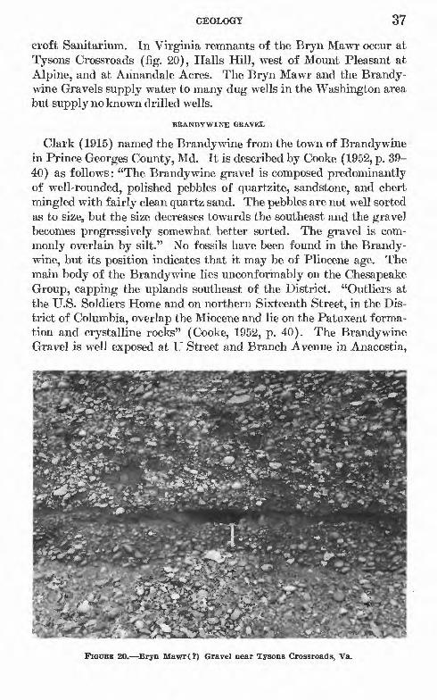
GEOLOGY 37
croft Sanitarium. In Virginia remnants of the Bryn Mawr occur at Tysons Crossroads (fig. 20), Halls Hill, west of Mount Pleasant at Alpine, and at Annandale Acres. The Bryn Mawr and the Brandy- wine Gravels supply water to many dug wells in the Washington area but supply no known drilled wells.
BRANDYWINE GRAVEL
Clark (1915) named the Brandy wine from the town of Brandy wine in Prince Georges County, Md. It is described by Cooke (1952, p. 39- 40) as follows: "The Brandy wine gravel is composed predominantly of well-rounded, polished pebbles of quartzite, sandstone, and chert mingled with fairly clean quartz sand. The pebbles are not well sorted as to size, but the size decreases towards the southeast and the gravel becomes progressively somewhat better sorted. The gravel is com monly overlain by silt." No fossils have been found in the Brandy- wine, but its position indicates that it may be of Pliocene age. The main body of the Brandywine lies unconformably on the Chesapeake Group, capping the uplands southeast of the District. "Outliers at the U.S. Soldiers Home and on northern Sixteenth Street, in the Dis trict of Columbia, overlap the Miocene and lie on the Patuxent forma tion and crystalline rocks" (Cooke, 1952, p. 40). The Brandywine Gravel is well exposed at U Street and Branch Avenue in Anacostia,
?<£=fcUs '. Mw#*fc.*sf*
FIGURE 20. Bryn Mawr(?) Gravel near Tysons Crossroads, Va.
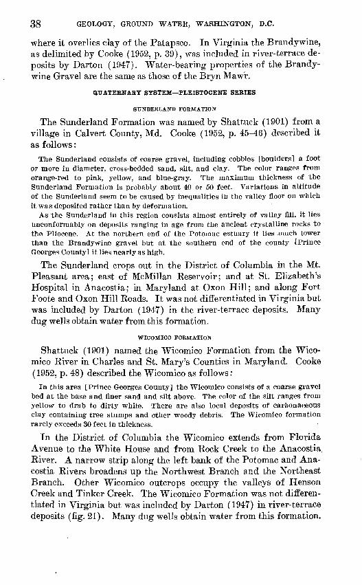
38 GEOLOGY, GROUND WATER, WASHINGTON, D.C.
where it overlies clay of the Patapsco. In Virginia the Brandywine, as delimited by Cooke (1952, p. 39), was included in river-terrace de posits by Darton (1947). Water-bearing properties of the Brandy- wine Gravel are the same as those of the Bryn Maw'r.
QUATERNARY SYSTEM PLEISTOCENE SERIES
SUNDERLAND FORMATION
The Sunderland Formation was named by Shattuck (1901) from a village in Calvert County, Md. Cooke (1952, p. 45-46) described it as follows:
The Sunderland consists of coarse gravel, including cobbles [boulders] a foot or more in diameter, cross-bedded sand, silt, and clay. The color ranges from orange-red to pink, yellow, and blue-gray. The maximum thickness of the Sunderland Formation is probably about 40 or 50 feet. Variations in altitude of the Sunderland seem to be caused by inequalities in the valley floor on which it was deposited rather than by deformation.
As the Sunderland in this region consists almost entirely of valley fill, it lies unconformably on deposits ranging in age from the ancient crystalline rocks to the Pliocene. At the northern end of the Potomac estuary it lies much lower than the Brandywine gravel but at the southern end of the county (Prince Georges County] it lies nearly as high.
The Sunderland crops out in the District of Columbia in the Mt. Pleasant area; east of McMillan Keservoir; and at St. Elizabeth's Hospital in Anacostia; in Maryland at Oxon Hill; and along Fort Foote and Oxon Hill Koads. It was not differentiated in Virginia but was included by Darton (1947) in the river-terrace deposits. Many dug wells obtain water from this formation.
WICOMICO FORMATION
Shattuck (1901) named the Wicomico Formation from the Wico- mico Kiver in Charles and St. Mary's Counties in Maryland. Cooke (1952, p. 48) described the Wicomico as follows:
In this area [Prince Georges County] the Wicomico consists of a coarse gravel bed at the base and finer sand and silt above. The color of the silt ranges from yellow to drab to dirty white. There are also local deposits of carbonaceous clay containing tree stumps and other woody debris. The Wicomico formation rarely exceeds 30 feet In thickness.
In the District of Columbia the Wicomico extends from Florida Avenue to the White House and from Kock Creek to the Anacostia River. A narrow strip along the left bank of the Potomac and Ana costia Kivers broadens up the Northwest Branch and the Northeast Branch. Other Wicomico outcrops occupy the valleys of Henson Creek and Tinker Creek. The Wicomico Formation was not differen tiated in Virginia but was included by Darton (1947) in river-terrace deposits (fig. 21). Many dug wells obtain water from this formation.
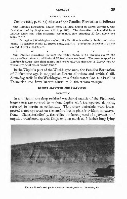
GEOLOGY 39
PAMLICO FORMATION
Cooke (1952, p. 50-51) discussed the Pamlico Formation as follows:
The Pamlico formation, named from Pamlico Sound in North Carolina, was first described by Stephenson (1912, p. 286). The formation is bounded by a marine shore line with estuarine reentrants, now standing 25 feet above sea level. * * *
In this region [Washington region] the Pamlico is entirely fluvial and estu arine. It consists chiefly of gravel, sand, and silt. The deposits probably do not exceed 30 feet in thickness.*******
The Pamlico formation occupies the valley floors of all streams except the very smallest below an altitude of 25 feet above sea level. The area mapped as Pamlico includes also tidal marsh and other alluvial deposits of Recent age as well as artificial fill, or "made land."
In the Virginia part of the Washington area, the Pamlico Formation of Pleistocene age is mapped as Recent alluvium and artificial fill. Some dug wells in the Washington area obtain water from the Pamlico Formation and from Recent alluvium in the stream valleys.
EECENT ALLUVIUM AND COLLUVIUM
coiitrviuM
In addition to the deep residual weathered mantle of the Piedmont, large areas are covered to various depths with transported deposits, referred to herein as colluvium. That these materials were trans ported is not apparent on the surface but is plainly evident in excava tions. Characteristically, the colluvium is composed of a pavement of angular weathered quartz fragments as much as 6 inches long lying
FIGUBE 21. Gravel pit in river-terrace deposits at Lincolnia, Va.

40 GEOLOGY, GROUND WATER, WASHINGTON, D.C.
directly upon the deeply weathered bedrock surface and overlain by several feet of reddish or buff-colored clayey silt, which generally con tains scattered quartz fragments. In some sections, one or more thin beds of weathered quartz fragments, more or less parallel to the bed rock surface, are the only indication of bedding, which elsewhere in the section may be obscure or lacking (fig. 22).
In the Piedmont of the Washington area, these deposits generally are exposed above an altitude of 300 feet, on uplands and hillsides alike. Their maximum observed thickness is more than 20 feet, though they may be much thicker. They probably originated as a result of rapid deposition of slope wash, as outlined below.
Quartz veins, which are common in all the basement rocks, are gen erally more resistant to erosion than the enclosing bedrock, and frag ments tend to accumulate on the surface while finer materials derived from the bedrock are carried away by sheet wash or by the wind. Downhill creep slowly spreads the accumulation of quartz fragments over the surface. The characteristic glossy, iron-stained appearance of the quartz in many places indicates long exposure to the elements. Later deposition buried the quartz pavement beneath an accumulation of clay and silt, which also contained a few scattered fragments of quartz throughout. Still later, erosion removed a part of the silt from the surface, leaving a second accumulation of quartz on the surface, which in turn was buried beneath a second accumulation of silt, ac-
FIGUEB 22. Colluvium overlying weathered schist of the Wissahiekon Formation, along University Boulevard east of Wheaton, Md.

GEOLOGY 41
counting for the interbedded quartz fragments. Subsequent erosion and dissection by streams left these deposits as remnants on the uplands.
A somewhat similar deposit, which appears to have formed in small tributary streams by a process that can be observed today, contains subangular to subrounded quartz fragments with intermixed clay, silt, and sand. The quartz fragments show only slight stream rounding, indicating that they have not been carried very far. Later erosion, after changes in the drainage pattern, has left the deposits above present stream courses.
The widespread occurrence of colluvial deposits greatly increases the difficulty of mapping the bedrock on the uplands and on the gentler slopes. The boundaries of the deposits are hard to distinguish because of the resemblance of the deposits to residual soils, and generally they are not detected unless exposed in road cuts or other excavations.
In addition to increasing the difficulty of geologic mapping, col- luvium has a most serious effect on construction projects, which has caused considerable trouble to builders and contractors. When col- luvium becomes saturated during wet weather it has the characteristics of quicksand .and tends to drain very slowly, although when dry it generally has satisfactory foundation and percolation properties. This behavior when saturated has caused expensive delays and serious foundation problems in some localities in the Washington area.
Because of the difficulties involved and the lack of time, this unit has not been mapped and is not shown on the geologic map. Probably some dug wells obtain domestic water supplies from the colluvium.
BECENT ALLUVIUM
The Recent alluvium is confined to stream channels and flood plains in the Piedmont as well as in the Coastal Plain and is generally only a few feet thick, but in some places it may exceed 20 feet. It consists of clay, sand, and gravel. Many dug wells obtain water from these deposits in the Washington area.
STBUCTUBE OF THE COASTAL PLAIN DEPOSITS
The bedrock surface in the Washington area, upon which the Cretaceous sediments of the Coastal Plain lie, dips to the southeast at an average rate of 125 feet per mile. The overlying formations dip progressively less. According to Meyer (1952), the Patuxent Forma tion dips to the southeast at about 80 feet per mile. The Arundel Clay dips 45 to 50 feet per mile, the Patapsco 30 to 50 feet, the Magothy 22 to 33 feet, the Monmouth about 30 feet, the Aquia about 20 feet, and the Nanjemoy 15 to 40 feet.
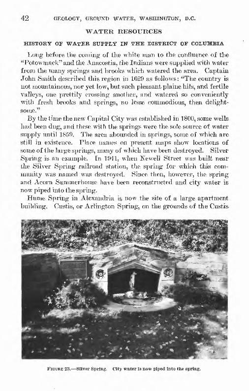
42 GEOLOGY, GROUND WATER, WASHINGTON, D.C.
WATER RESOURCES
HISTORY OF WATER SUPPLY IN THE DISTRICT OF COLUMBIA
Long before the corning of the white man to the confluence of the "Potowmack" and the Anacostia, the Indians were supplied with water from the many springs and brooks which watered the area. Captain John Smith described this region in 1G29 as follows: "The country is not mountainous, nor yet low, but such pleasant plaine hils, and fertile valleys, one prettily crossing another, and watered so conveniently with fresh brooks and springs, no lesse commodious, then delight some."
By the time the new Capital City was established in 1800, some wells had been dug, and these with the springs were the sole source of water supply until 1859. The area abounded in springs, some of which are still in existence. Place names on present maps show locations of some of the large springs, many of which have been destroyed. Silver Spring is an example. In 1941, when Newell Street was built near the Silver Spring railroad station, the spring for which this com munity was named was destroyed. Since then, however, the spring and Acorn Summerhouse have been reconstructed and city water is now piped into the spring.
Hume Spring in Alexandria is now the site of a large apartment building. Custis, or Arlington Spring, on the grounds of the Custis.
FIGURE 23. Silver Spring. City water is now piped Into the spring.

WATER RESOURCES 43
estate, now Arlington National Cemetery, was a favorite picnic spot before the Civil War.
In the District of Columbia, the name Carroll Springs was given to a community surrounding a group of springs on New Jersey Ave nue, two or three blocks south of the Capitol (Brown, 1930, p. 5). Takoma Spring, though now unused, is still in existence at the corner of Elm and Poplar Avenues in Takoma Park.
Many anecdotes of fact and fiction about some of the springs in this area have come down through the years. The big spring at the Kingwood Farm southwest of Alexandria is said to have been a favorite stopping place of George Washington. A large spring (prob ably called Washington Spa Springs) formerly at the east side of Bladensburg Road, just south of the entrance to Fort Lincoln Ceme tery, figured in the battle of Bladensburg in 1814. Proctor (1930, p. 357) wrote: "Commodore Barney was taken prisoner, having ordered his officers to leave him where he lay bleeding at the spring * * *." Barney's wounds were treated by the British, and he was later released.
Silver Spring was named by Francis Preston Blair, the former owner of Blair House on Pennsylvania Avenue (now used as a guest house by the President). In 1842 Blair happened on the spring while in pursuit of a runaway horse. The water bubbling up through the mica and sand glistened in the sunlight, and this effect suggested the name. Blair later purchased a large tract of land, which included the spring, and built a country home.
In the seventy-fifth anniversary history of Takoma Park (Olm- stead and others, 1958, p. 16), it is related that when the Indian Chief Powhatan was wounded near the present site of Philadelphia he was taken to ,a "wonderful, healing spring" north of the Potomac pre sumably Takoma Spring referred to as Big Spring to distinguish it from lesser springs in the vicinity.
The Takoma spring was sold to the Takoma Park Springs Co., which in 1891 began to bottle and sell the water. According to Olm- stead (1958, p. 17) this was tolerated until the company fenced in the spring to prevent access by the public, whereupon the irate citi zenry took things in their own hands and tore the fence down. In vestigation showed that "the terms of the sale specifically intended to retain the spring in public use and that the claim of the owners was void * * *." The town then acquired possession of the spring and park. The Takoma spring (fig. 24) was in use during the drought of 1932, when people from many miles around came for water.
711-570 0 64 4

44 GEOLOGY, GROUND WATER, WASHINGTON, D.C.
Numerous other springs, whose names are no longer recorded on maps, have been destroyed, but former locations may be determined from records of the District Government, and the Corps of Engineers, from newspaper files, and from local historical writings.
One of the largest springs in the city, "the celebrated Ridge [or City] Spring," \vas on the north side of C Street between Fourth and Sixth Streets NW. Water from this spring was piped to the yard of Center House which \vas opened in 1804 at the corner of Ninth and D Streets NW. (Brown, 1930, p. 321). In 1808, water from this spring \vas conveyed by \vooden (bored-log) pipeline to residences in the 600 block of Pennsylvania Avenue NW. The cost of pipe and installation \vas borne by the owners \vho used the service. This is the first record of \vater supply for public use by pipeline in the city (Orndorff, 1962).
A large spring, at Ninth and F Streets NW. known variously as Federal, Caffrey's or Hotel Spring, \vas "concealed from view" \vhen the Masonic Temple was built (Brian, 1914, p. 559). Water \vas piped from this spring to Pennsylvania Avenue in 1809, to serve the blocks between 9th and 14th Streets NW. This wTas the first pipeline to wThich the District Government contributed a part of the cost; one-third of the cost was borne by the District, two-thirds by the users. After this, no further extensions of pipelines wTere made until 1823, \vhen water from a spring in the "public space" of 13th Street NW., north
FIGURE 24. Takoma. Spring, still flowing but unused.

WATER RESOURCES 45
of Eye Street, was piped southward along 13th and 14th Streets. During the course of several years these lines, which were partly of bored logs and partly of cast iron, were extended south to Ohio Ave nue, east to llth Street, and west to 15th Street NW. (Orndorff, 1962).
Congressional or Smith Spring, now inundated but marked by a circular brick structure in McMillan Reservoir, was purchased in 1833. It supplied water by pipeline to the Capitol building in 1834. In 1837 the pipeline was extended to hydrants along Pennsylvania Avenue (J. C. Smith, written communication, 1962).
Delay in improving public facilities must have been as common in the nineteenth century as it is today. In 1819 Congress provided an appropriation to have water piped from a group of springs in what is now known as Franklin Park to the White House and executive buildings, which at that time were supplied from wells (Brian, 1914, p. 65). The project was not completed until 1834 because of "un willingness of the government to pay what was regarded as a high price in 1819" (op. cit., p. 65).
Cool Spring, a large spring near 15th and E Streets NE., also was called Young's or Stoddert's Spring after former owners; later it became known as Federal Spring, a duplication of the name used sometimes for Caffrey's Spring (Brian, 1914). An ice plant was built at this site and the water is still in use for cooling at the plant. This is one of two springs in use commercially in the Washington area. The other is southwest of Kockville, where the water is bottled and distributed for drinking.
No further details are available concerning a spring in City Hall Park, now Judiciary Square, which also supplied water by pipeline to the nearby area. There were many other springs of considerable importance in the old city, but it is doubtful if any of them were used to supply pipe systems.
The waterlines from the springs were maintained and extended from year to year. By 1850 most of the area south of the springs to Pennsylvania Avenue and between 1st and 15th Streets NW. was served by pipeline. Most of the lines were connected to public hy drants or "pumps," but some supplied service lines into private premises.
According to Orndorff (1962) :
an act of the City Council dated August 5, 1812, provided general authority "for sinking of wells and erecting of pumps, conveying of water in pipes, and fixing of hydrants for the improvement of springs and other purposes." Under this act, the Mayor * * * could cause one-half of the cost of such improvements to be assessed against the resident beneficiaries. In addition to the construction, improvement, and maintenance of springs, wells and pipelines, the city con structed large brick cisterns or reservoirs in strategic street intersections to store water for fire fighting.

46 GEOLOGY, GBOUND WATER, WASHINGTON, D.C.
Wells were a great convenience, even if located on the corner of a block. However, the more affluent had wells dug in their own yards. Others used the public pumps.
Fortunately the chief source of soil contamination in centers of population was never a problem in Washington. On May 13,1805, an ordinance was approved prohibiting the use of privy pits.
The Intelligencer of December 1, 1849, stated that for more than a third of a century the city had made use of the "rich gifts of nature of under-ground springs which rise up wherever a well is dug." However, by midcentury the supply was no longer adequate for a pop ulation that had increased to 51,000. The demand was so great that it was impossible to prevent private citizens from tapping the pipe lines to public buildings (Brian, 1914, p. 305).
Several surveys had been made for a public water supply. Notes on L'Enfant's map of 1792 suggested that water from a branch of Tiber Creek be "conveyed to the high ground where Congress House stands," from Keedy Branch to the President's House, and that Pine Creek (now Piuey Branch) be "turned into James White Branch to supply the city." These suggestions were never carried out, except that Congressional or Smith Spring, which was the source of a branch of Tiber Creek, was piped to the Capitol building.
At various times consideration for a public supply had been given to the Potomac above Great Falls, Rock Creek, the Anacostia Eiver, and the numerous wells and springs in the District (Somervell, in Proctor, 1930, p. 613).
"In a letter written in 1798, General Washington expressed a belief 'that the water of the Potomac may, and will be brought from above the Great Falls into the Federal City, which would, in future, afford an ample supply of this object' " (Orndorff, 1962).
In the years 1850-52, appropriations were made for a study of the best way of supplying water to the city, and by 1853 Capt. M. C. Meigs of the U.S. Army Corps of Engineers began construction of a project to bring water from the Potomac to the city. The project consisted of a dam above Great Falls, 9 miles of 9-foot conduit to Dalecarlia Reservoir (a 46-acre reservoir in Little Falls Branch), and 2 miles of 9-foot conduit from Dalecarlia to Georgetown Reser voir. From Georgetown the water was to be distributed through cast-iron mains to other parts of the city.
By 1859 construction had been partly completed and water from Little Falls Branch, impounded in Dalecarlia Reservoir, was turned into the system. Finally, on December 5,1863, after delays caused by the war, water from above Great Falls began flowing into the mains (Orndorff, 1962).
WATER RESOURCES 47
When the system was first put into service the water was at times polluted or made turbid by Little Falls Branch. Dalecarlia was then bypassed at times of pollution or turbidity by the building of a con duit around it, and water from Little Falls Branch was used only when in good condition, or for emergencies. This was the situation until 1895 when a tunnel was built to carry Little Falls Branch around Dalecarlia Reservoir to the Potomac River.
McMillan Reservoir (38 acres for sedimentation and storage) was completed in 1902 and connected to Georgetown Reservoir. Even with the improvements at Dalecarlia, the water, now obtained entirely from the Potomac, was frequently turbid and remained so periodically until a filtration plant was completed in 1905.
The filtration plant left something to be desired the water from the Potomac was still turbid at times and remained so until January 1911, when coagulant was added. Thereafter the water was clear at all times (Somervell, in Proctor, 1930).
The next year the problem of pollution of the ground water made its appearance. According to the Washington Evening Star of Feb ruary 6, 1906:The recent action of Dr. W. E. Woodward, the health officer, in condemning the water from the springs in Franklin Square, between L, K, 13th and 14th Streets, declaring it to be deleterious to the public health, has caused comment in various quarters. For 75 years the springs have furnished water for use at the White House, the State, Treasury, War and Navy Departments, and many houses in that portion of the city, during which time there has been no complaint of the quality of water. Many hale, hearty old men and women, some of them octo genarians, have been lifelong users of the water, it is claimed, and have fared fully as well as those supplied by other springs * * *.
Ground-water supplies from wells also became suspect, according to the Washington Evening Star of August 24, 1907: "Partisans of the public pumps, organized under the name of the District of Colum bia Protective Association, held a meeting at Society Temple last night and condemned the action of the Commissioners in abandoning a number of wells about the city." But in spite of the protests the use of public shallow wells and springs was discontinued, at least in the central part of the city. However, the objections had become so violent that when pollution was suspected in the spring on 13th Street, water from the Potomac was turned into the lines at night without the public knowing it.
Although the public use of shallow wells and springs was forbidden, many that were privately owned remained in use until a few years ago, and at the present time the District does not require permits for drilling private wells. However, cross-connections with the public system are strictly forbidden and large commercial wells are metered so that a sewer charge can be made..

48 GEOLOGY, GROUND WATER, WASHINGTON, D.C.
Long after the central part of the city was supplied with water from the Potomac, the District Government continued to contract for the drilling of deep wells for schools in the outlying parts of the District. The Annual Eeport of the District for J910 listed 11 shallow and 30 deep wells in use, presumably for public supply. The 1920 report shows that maintenance work was done on 2 springs and 23 wells.
In 1920 it was again found necessary to augment the public water supply. At this time additional sources considered were the Patuxent Eiver, the Potomac Eiver at Little Falls, and the Potomac above Great Falls. A new intake was installed about 100 feet above the old dam above Great Falls and a new conduit was built parallel to the old one, to Dalecarlia. A new filtration plant was constructed just below Dalecarlia (Somervell, in Proctor, 1930).
As the suburbs expanded, water had to be provided for communities adjacent to the District. In March 1917 and April 1926, legislation was enacted to allow water to be supplied to the Washington Suburban Sanitary District in adjoining Maryland and to Arlington County Sanitary District in Virginia. These areas encompassed 95 square miles in Maryland and 25 square miles in Virginia.
In 1928 Washington had a water supply "so abundant that it will provide water for several more decades though the population in creases at the present rate of 11,000 a year" (Proctor, 1930).
In the early 1900's drilled wells began to supplant dug wells. Most of the new wells were artesian, drilled in the Coastal Plain for com mercial establishments. Some of these wells are still in use within the District of Columbia and in nearby Maryland and Virginia.
Many of the outlying suburban and rural areas surrounding Wash ington are not supplied with city water. In these places wells and springs are the sole source of supply.
PRESENT STATUS OF WATER SUPPLY IN THE AREA
DISTRICT OP COLUMBIA
Until 1959 the public water supply for the District of Columbia, and Arlington and Falls Church, Va., was taken from the Potomac River by means of the diversion dam above Great Falls. A new diversion dam and pumping station with installed pumping capacity of 450 mgd (million gallons per day) were constructed at Little Falls and put into operation in the summer of 1959. When the present filtering capacity of 204 mgd is increased to 333 mgd, the system will be capable of supplying the District and adjacent parts of Virginia until the early 1990's (J. C. Smith, written communication, 1962). The Army Engineers are now (1962) completing a comprehensive study of the Potomac River basin in order to select the best plan to supply needs in the more distant future.
WATER RESOURCES 49
Within the District approximately 14 private wells in Coastal Plain formations supply water for a variety of commercial establishments such as a storage warehouse, a railroad terminal, a dairy, a hotel, a theatre, retail establishments, and light industry. These wells together pump approximately 1.5 mgd. Two wells in the Piedmont west of Rock Creek supply a few gallons per minute for irrigation;
SUBURBAN MARYLAND
Public water supply in Maryland in a 427-square-mile area adjoining the District of Columbia is furnished by the Washington Suburban Sanitary Commission. In 1961 an average of 49 mgd was supplied to a population of about 600,000. Water is obtained from two reservoirs on the Patuxent River and from diversion works on the Potomac River placed in operation in 1960. A small reservoir and filtration plant on Northwest Branch is maintained at Burnt Mills, near Silver Spring, to provide for emergencies and peak loads. Three wells are operated by the Commission in Prince Georges County and others are planned.
In all, the facilities of the Sanitary Commission have a total capacity of about 110 mgd, and an additional 90 mgd can be provided by ex pansion of the Potomac River plant. These facilities are considered adequate to supply the population expected in the area until the year 2000.
The city of Rockville, until October 1958, was supplied with water from 35 wells. Since that time the city has obtained its water from a plant on the Potomac River opposite Bealls Island. The city main tains 17 of its wells on a standby basis for emergency use.
SUBURBAN VIRGINIA
Arlington County and Falls Church obtain public water supplies from the District of Columbia system. Falls Church in turn sells water to the Fairfax County Water Authority and also supplies residents in a 22-square-mile area in adjacent Fairfax County. At least 10 privately owned water companies, most of which rely on wells or a combination of ground water and surface water, supply northern Virginia in the Washington area.
The Alexandria Water Co., the largest system in northern Virginia, obtains most of its water from a dam on Occoquan Creek, about 20 miles southwest of Alexandria; it supplies the city of Alexandria and the adjacent part of Fairfax County, including Fort Belvoir.
In 1957 the Fairfax County Water Authority was established to purchase the private water companies and integrate them into a county system. By the end of 1961, four private companies had been acquired.

50 GEOLOGY, GROUND WATER, WASHINGTON, D.C.
THE HYDRCXLOGIC CYCLE
Ground water in the Washington area is derived from precipitation in nearby areas not more than a few miles distant. Eain falling upon the ground may (1) run off, (2) seep into the ground, (3) be transpired by plants, or (4) be evaporated. The relative proportion of rainfall that follows each course is dependent upon many factors, including the duration and rate of precipitation, the topography, the physical properties and degree of saturation of the soil, the kind and amount of vegetation, and the climate.
Of that, portion of the rainfall that infiltrates into the ground, a part may be returned to the atmosphere through transpiration by vegetation or through evaporation. The remainder, acted upon by the force of gravity, may tend to move downward toward the water table or, in response to capillary forces, may move upward, downward, or laterally in the direction of decreasing moisture content. Within wide limits, the. drier the soil the greater is its affinity for water.
Between the land surface and the water table is the zone of aeration, which is not saturated but contains water held by molecular attraction within the interstices of the earth materials and water in downward transit to the water table. This is called suspended water, or vadose water. The zone of aeration may be divided into three parts: (1) the zone of soil water, (2) the intermediate zone, and (3) the capillary fringe. (See fig. 25.)
WATER
SURFACE
ZONE OF SATURATION (GROUND WATER)
FIGURE 25. Zones of subsurface water.

"WATER RESOURCES 51
The zone of soil water, which lies nearest the surface, discharges water to the atmosphere by evaporation and by transpiration from plants and to the zone below it by gravity.
Below the zone of soil water is the intermediate zone, through which water not retained by the zone above seeps downward to the water table. Where the water table lies close to the surface, the intermediate zone may be absent.
Just above the water table, which marks the surface of the zone of saturation, is the capillary fringe, where water is held by capillary forces. The height of the capillary fringe is determined by the texture of the material in whicli it lies; its height is greatest in fine-grained materials and least in coarse-grained materials.
Some water is held at all times in the zone of aeration by molecular attraction. If the soil in this zone is more moist at the land surface than below, capillary forces act downard, aiding gravity to move the water toward the water table. When the soil at the surface becomes drier than the soil below, capillary action is reversed and opposes the action of gravity. If the capillary forces acting upward balance the force of gravity, the water in the zone of aeration is in equilibrium and does not move.
When the water seeping downward reaches the zone of saturation, it moves laterally, by gravity flow, toward lower elevations and ulti mately, unless intercepted by wells, to places of discharge springs, seeps, or surface-water bodies.
The movement of ground water described in the preceding para graphs applies to unconfined water in granular materials, such as al luvium or the weathered residual blanket that overlies the metamorphic and igneous rocks of the Piedmont. Where permeable material, such as sand and gravel, alternates with relatively impermeable material, such as clay, entirely different conditions prevail. If the alternating beds are inclined, water entering at the outcrop of the permeable beds will move downdip under pressure, being confined by the impermeable clay beds above. Then, if a well is drilled through the clay into the water-bearing sand or gravel (aquifer) below, the water, being under pressure, will rise some distance above the bottom of the clay bed.
This is now an artesian well, and if the water rises high enough to flow at the surface, it is a flowing artesian well. These conditions are illustrated in figure 26.
SURFACE WATER
PRINCIPAL STREAMS AND THEIR TTSE IN THE AREA
The Potomac River is the only stream within the area used as a public water supply. Alexandria Reservoir, now called Lake Bar- croft, was abandoned by the Alexandria Water Co. about 1949 when

52 GEOLOGY, GROUND WATER, WASHINGTON, D.C.
a new dam was built on Occoquan Creek, south of the area. In 1959 Fort Belvoir contracted to obtain water from the Alexandria Water Co., permitting abandonment of Belvoir Reservoir on Accotmk Creek. The only other surface supply comes from the Patuxent River, which is north of the area, and is supplied to communities in nearby Mont gomery and Prince Georges Counties, partly within the report area, by the Washington Suburban Sanitary Commission.
GROUND WATER
Ground water in the Washington area is obtained from both con solidated crystalline rocks and uiiconsolidated sedimentary rocks. The exposures of these two rock types are almost equally divided by the Fall Line running diagonally from, roughly, the northeast to the southwest corners of the mapped area.
OCCURRENCE IN CRYSTALLINE ROCKS
In the Piedmont of this area ground water occurs almost exclusively in the crystalline (metamorphic and igneous) rocks or in the residual materials developed upon them. Only a few wells obtain water from the alluvium in the stream valleys or from colluvium.
//WATER TABLE ' > , I ', ! ,
^Water-table Stream ^-^Water-tabje
/ / /
lan well
INTAKE AREA'' '/ / V' /'//'/AQUIFER B ' ' ' ' ' '/
Flowing artesian.well screened in two aquifers
Flowing artesian ' well
Water in weathered and fractured bedrock and permeable sediments (water table)
EXPLANATION
Piezometric surface*, Aquifer A
Piezometric surface. Aquiter B
The Piezometric surface is the theoretical level to which water will rise in a well screened in a given aquifer
Water here will rise above the impermeable layer where the aquifer is pene trated by wells
THE CAUSE OF
INTAKE AREA ARTESIAN FLOW
Holes
Water will "seek its level" through the small holes drilled in lower end of the tube
FIGURE 26. Diagram showing hydrologic principles prevailing in the Washington, D.C., area.
WATER RESOURCES 53
Crystalline rock, because of its compact fabric, yields little or no water to wells. Ground-water movement is controlled largely by fractures joints, cleavage planes, and faults and in places by con tacts between rock bodies. Fortunately most of the rocks in this area have been considerably disturbed by earth movement and so contain water-bearing structures to some degree.
Joints commonly occur in sets of three, together called a joint system. Each set consists of approximately parallel fractures, which may be .closely or widely spaced a few inches to many feet apart. The three sets as a rule are disposed at right angles to each other; two sets are almost vertically inclined, and a third set is nearly flat lying or slight ly inclined.
In most schistose rocks, cleavage planes are caused by shearing or compressional forces. These forces tend to orient the rock minerals in parallel, creating planes of weakness along which the rock tends to split.
One wall along a fracture may move with respect to the opposing wall and a shear zone or fault ensues. The movement may create a brecciated (crushed) zone, which would serve as a channel for the movement of ground water. On the other hand, an impermeable zone of clay (gouge) may be formed, according to the type of materials, the nature of the forces involved, and the depth below the surface at which the movement occurred. Such a clay-filled structure would serve as a barrier to the movement of ground water.
Contacts between the country rock and the igneous intrusive rocks may have similar effects on the movement of ground water; that is, the contact may be shattered, creating a ground-water channel, or it may be effectively sealed, creating a barrier.
The joints break down large rock masses into smaller units. Weathering tends to enlarge the joints and thus facilitates the move ment of ground water in relatively impermeable rocks.
In the metamorphic and igneous rocks below the residual soil level, movement of ground water, therefore, is controlled by the rock struc ture. If the water table lies below the top of the rock rather than in the weathered overburden, influent seepage, instead of moving di rectly down to the water table, moves along open fractures at a rate dependent upon the amount of water supplied by the weathered over burden and the size and inclination of the openings. If the openings are interconnected, one water table will result; single fractures or groups of fractures may have separate water levels, depending upon the altitude of the point of discharge.
Ground water in these Piedmont rocks is usually thought of as unconfined; that is, controlled by water-table conditions rather than
54 GEOLOGY, GROUND WATER, WASHINGTON, P.O.
artesian conditions. This is generally true. However, some drilled wells in the Piedmont fit the definition of an artesian well; that is ground water in the well is at sufficient pressure to rise above the level at which it enters the well, although not necessarily rising to or above the ground surface (Sayre, 1936, p. 33). Here the artesian pressure is caused by water moving downward along an inclined structural feature, such as a joint or fault, the upper block or so-called hanging wall acting as a confining layer. Even though these aquifers do not extend over large areas, as many artesian aquifers do, they are truly artesian as are the wells that tap them.
OCCURRENCE IN SEDIMENTARY ROCKS
In the Coastal Plain, ground water occurs under unconfined (water- table) and confined (artesian) conditions. Dug or bored wells or shallow drilled wells in the upper Coastal Plain formations obtain water from the water table, and the characteristics of these wells are similar to those in the residual soils of the Piedmont. If, as is common at greater depths, the drilled wells penetrate a confining bed of clay (aquiclude), the water in the sand and gravel (aquifer) beneath, being under pressure, will rise above its source in the well and may even flow at the land surface. Only two flowing arteisan wells (WE- Bb-2 and AX-Ca-10) are known in the area (Johnston, 1961, table13).
The geologic setting of artesian wells, as well as of water-table wells, is shown in figure 26. It is seen that the recharge or intake areas for the aquifers are at. the outcrop of the aquifers. Rain falling on these areas seeps into the ground and moves downdip in the aquifer until it is intei'cepted by a well or discharged naturally.
An erroneous belief prevails that ground water in the Washington area originates at a considerable distance, such as in the Blue Ridge or even in the mountains of Pennsylvania, This cannot be true, be cause the Piedmont has no water-bearing structural feature in the Washington area that has a continuous areal extent of more than a few miles. The water from wells in the Piedmont and from the shallow water-table wells in the Coastal Plain originates as precipitation in or near the local watershed or basin in which the well is located. In the Coastal Plain most of the water from artesian wells originates in the outcrop area of the aquifer involved, which in the Washington area probably would not be more than a few miles distant.
DEVELOPMENT
WELLS AND SPRINGS
Because of time limitations, no attempt was made to inventory all the wells and springs in the Washington area. The wells selected

WATER RESOURCES 55
probably represent not more than 25 or 30 percent of the total number existing at the time the survey was made. However, complete data are available for most of the wells inventoried and are shown in table, 13 (Johnston, 1961). The wells listed are typical of the Washington area.
WELL-NUMBERING SYSTEM
The well map (pi. 2) shows the boundaries of the quadrangles that make up the Washington and vicinity map. Each quadrangle is divided into nine rectangles by lines drawn through the 2%-minute marks. The rectangles thus formed are lettered A, B, and C from top to bottom and a, b, and c from left to right. In the text a single- or double-letter prefix in uppercase indicates the quadrangle as follows:
Quadrangle
R_______________________________________ Eockville K____________________________________ KensingtonBT_____________________________________ Beltsville FC___________________________________ Falls Church WW_______________________________ Washington West WE________________________________ Washington East AN _ ________________________________ AnnandaleAX _ _____________________________ AlexandriaAC _________________________________ Anacostia
The wells and springs are numbered consecutively in each quad rangle, the pair of uppercase and lowercase letters indicating the rectangle in the quadrangle and the single or double uppercase letter the quadrangle. For example: R-Ba-1 indicates the first well num bered in the northwesternmost rectangle of the Rockville quadrangle, and AC-Cc-3 is the last well numbered in the sontheasternmost rectangle of the Anacostia quadrangle. The upper tier of rectangles of the Rockville, Kensington, and Beltsville quadrangles is not shown on the Washington and vicinity map, hence the numbering in each of these quadrangles begins with Ba, Bb, or Be.
Foundation test borings are designated similarly; they are lettered consecutively with lowercase letters in each rectangle. For example: WW-Cc-a is the first boring in the sontheasternmost rectangle of the Washington West quadrangle.
SPRINGS
In all, 23 springs are listed by Johnston (1961, table 13) 19 in the Piedmont and 4 in the Coastal Plain. Yields range from 1 to 50 gpm. Of the 10 improved springs, 5 are in use and 2 of these (R-Bc-2 and WE-Ca-5) are used commercially.
56 GEOLOGY, GROUND WATER, WASHINGTON, D.C.
CONSTKTJCTION METHODS
Wells in the Washington area are of three types: drilled, bored, and hand-dug. Until 3 or 4 years ago drilled wells were constructed by two methods: cable-tool drilling, also known as percussion or churn drill ing, and rotary drilling. Eecently a third method has been coming into use, known as down-the-hole drilling, which might be called a com bination of percussion and rotary drilling.
The cable-tool or percussion drill rig uses a heavy chisel-pointed bit suspended by a steel cable. The bit cuts by being alternately raised and dropped inside a steel casing set into the ground. In the past these rigs have been used .almost exclusively for drilling wells in the Pied mont and to a large extent in the Coastal Plain. Cable tools are capable of drilling most of the hard rocks of the Piedmont, although some rocks are so hard that the drilling is extremely slow.
As the name implies, rotary rigs drill wells by applying a rotary motion to a steel bit attached to the end of a string of hollow rods. The rotary method is particularly adapted to drilling in the Coastal Plain, especially for drilling large-diameter gravel-packed wells. However, at least one rotary rig is in use in the Piedmont in this area and it is reported to operate effectively in hard rock.
The chief advantage of the new down-the-hole rig is the speed with which it drills in hard rocks a decided advantage in the Piedmont. It can also function as a rotary rig. The machine consists chiefly of an air hammer fitted with a tungsten-carbide bit at the end of a string of hollow rods. Cutting is accomplished by a combined reciprocating and rotary motion. Although the machines are very expensive, the high speed more than offsets the difference in cost.
Bored wells are similar in characteristics to dug wells but are con structed by large-diameter (24- to 48-in.) boring machines or earth augers which are incapable of drilling in rock and operate best in soft residual or alluvial materials. In spite of this limitation, large numbers of bored wells have been constructed in the Virginia part of the area, and in favorable locations they provide an adequate and dependable water supply for the average household. For some reason very few bored wells have been constructed in the Maryland part of the area.
COMPABISON OF WELL TYPES
Drilled, bored, and dug wells each have certain advantages as well as disadvantages. Theoretically, though not always actually, the drilled well in the Piedmont obtains its water from openings in the bedrock. When precipitation seeps downward from the ground sur face through the soil, it enters the natural openings in the hard rock beneath and then moves along these openings to the place where it is intercepted by the well. A drilled well, 100 feet or more deep, is not likely to fail in dry weather, and if the bottom of the casing is properly

WATER RESOURCES 57
seated in the rock, the chance of pollution from surface sources is minimized, though perhaps not entirely eliminated.
In contrast to the drilled well, the bored or dug well in the Pied mont receives all its water from the weathered materials overlying the bedrock. Where the weathered materials are thin, the water table may decline below the bedrock surface in dry weather, and the water supply will fail. If water is not found above the bedrock surface in a bored well, the well must be abandoned or deepened by hand. Hand digging is difficult below the water table, even in unconsolidated de posits, and consequently many wells are not deep enough to provide for the natural fluctuation of the water table. For this reason, bored or dug wells (fig. 27) are best adapted to sites where the water table is near the surface, as low on a hillside or in a valley. Being of large diameter, they provide greater storage capacity than a small-diameter drilled well.
Locally, especially in some of the granite intrusions, bedrock is so little fractured that it will yield only very small amounts of water to drilled wells. In these places, provided the weathered zone is sufficiently thick, a bored or dug well may suffice and may be the only alternative.
Bored or dug wells are most commonly subject to pollution because they are supplied from near-surface water, and their construction seems to invite inadequate protection at the land surface. Chlorina- tion may be advisable, and frequent tests should be made to insure that the water is free from contaminants. On the other hand, water from bored or dug wells usually does not contain objectionable amounts of iron a common constituent of water from some drilled wells.
In the Coastal Plain somewhat different construction techniques are necessary for drilling wells. Here two types of drilled wells are commonly in use: the tubular drilled well and the gravel-packed well (fig. 27). Both types are drilled by rotary rigs, but the tubular type can be drilled by cable tools. A rig that employs the principle of jetting is in use farther east but so far as is known has not been used in the Washington area.
Most drilled wells in the Coastal Plain employ screens to keep fine sand and silt from being pumped into the system. It is pos sible to avoid the use of a screen in a few places, but the pump intake must be well above the bottom, and pumping must create no turbulence. Some wells are screened in more than one aquifer, the im permeable beds between being cased off with unperforated pipe.
In some places in the Coastal Plain, gravel-packed wells are an advantage. A well of this type may be of large diameter throughout, or it may be underreamed to a large diameter opposite the aquifer.

DU
G
or B
OR
ED
W
ELL
DR
ILLE
D
WE
LL
(Gra
vel-p
acke
d)D
RIL
LED
W
ELL
fes
-
Out
er c
asin
g-
Inne
r ca
sing
P
ump
colu
mn
Pum
p dr
ive
sha
Pum
p im
pelle
rs
Scr
een
Dou
ble
casi
ng a
nd
grav
el p
acki
ng
Scr
een
Sw
aged
plu
g -v<^*!-
*:'"
v,x'
:.:;
g o ss o I H
SS 1 I S e o
FIG
CEB
27. D
iagra
m s
how
ing
type
s of
wel
ls i
n th
e re
port
are
a.

WATER RESOURCES 59
In. either case the annular space between the screen and the wall of the well is filled with gravel, grading from coarse against the screen to fine at the periphery of the hole. The advantages of the gravel-packed well are (1) that it allows use of a screen with larger openings than otherwise could be used, permitting more water to pass, and (2) that it increases the effective diameter of the well. However, gravel-packed wells are not always an advantage and may not be necessary. In m.any places careful developing of the well, which removes fine-grained material nearest the screen, will make it fully as effective as a gravel-packed well.
PROBLEMS
In the Piedmont many drilled wells are fed, at least in part, by water from the weathered zone. Attempts to seal off the upper water are not always effective, even if the driller makes a conscientious effort to seat the casing in the hard rock. Furthermore, this may not always be desirable, as sealing off the water from the weathered zone may reduce the yield below the minimum requirement. On the other hand, if the bottom of the casing is not driven tightly into the rock, pollution may result, or, in certain types of rock, silt and mud may be drawn into the well. In some places iron leaches out of the weathered zone and tends to accumulate near the top of the bedrock, and the water will contain objectionable amounts of iron. In the fine-grained clay schist or phyllite, the casing may appear to be firmly seated but, after the well is in use for a few days, the rock tends to soften and large amounts of micaceous silt may be pumped. In some places it will then be possible to drive the casing down still farther and thus eliminate the trouble. If this is not effective, the application of cement to the bottom of the casing (grout ing) may stop the silting. Where high iron content in the water results from iron entering the upper part of the hole, installing a packer around a smaller inner pipe in the open hole may end the problem.
It must be borne in mind, however, that the water withdrawn from openings in the hard rock reaches those openings by percola tion through the overlying weathered zone. Proper well construction should be directed primarily toward preventing polluted, near-sur face water from moving down the disturbed zone immediately outside the casing and entering the well.
In the Coastal Plain iron in the water is often a problem, but if an alternate aquifer cannot be found, the only remedy is to install a water conditioner of some type. Water from some aquifers con tains more iron than others so that the quality of the water varies from place to place. Unfortunately it is not possible with the infor mation at hand to pinpoint the areas of greatest or least iron content.
711-570
60 GEOLOGY, GROUND WATER, WASHINGTON, D.C.
SELECTION OF WELL SITES
In the Piedmont the topography is commonly controlled by the structural features of the rocks. The surface traces of the major structural features are etched in relief by the processes of erosion. As suggested by Mundorff (1948, p. 25-27) and others, interpretation of rock structure by topographic features is an aid in selecting favor able well sites.
The two principal structural features reflected in the topography are the cleavage or schistosity and the joint system. The schistosity and one set of joints parallel to it generally have a northeast-southwest trend. Another set of joints strikes northwest nearly at right angles. These tliree features are commonly steeply inclined. A third set of joints is only slightly inclined and does not influence the topography greatly. Other structural features which may be expressed in the topography and which may carry water are fault and contact zones. Where the streams have cut into the bedrock, they are commonly adjusted to the structural pattern ,and indicate zones of weakness wherein the rocks are permeable and yield water freely. Wells drilled along these zones of weakness or, better still, at the intersection of two zones have the greatest possibility of success. However, unless the zone is nearly vertical or very wide, a vertical hole drilled on its surface trace may not remain in it at the depth required. Therefore, the dip of the structural feature should be determined from nearby outcrops if possible. However, few such features maintain a constant dip. Furthermore, these principles cannot be used with any assurance of success near the heads of gullies, where the streams have not ad justed themselves to the bedrock structure, or in wide alluviated valleys, where a zone of weakness concealed beneath the alluvium may lie anywhere in the valley.
Conversely, just as gullies and valleys indicate zones of weakness in the rocks, hills are commonly underlain by less permeable, harder, or more resistant rocks. This is one reason that low hillsides, gullies, and valleys are better well sites than hilltops. Also, the water table as a rule is nearer the surface in low areas and near streams than it is on hilltops and is less subject to long-term fluctuations caused by climatic variations.
In many places in the Piedmont, quartz veins of various sizes cut the bedrock, and some wells tapping these veins yield greater than average supplies of water. Quartz, called flint by drillers, is a brittle mineral and is commonly extremely shattered. Some wells in the Piedmont obtain their water from quartz veins that generally were struck by chance. If a fractured quartz vein can be intercepted at sufficient depth below the water table, it is likely to be a highly productive aquifer.

WATER RESOURCES 61
In selecting a site for a bored or dug well, topography is all im portant. As with drilled wells, bored or dug wells in low places gen erally have the largest yields and are most dependable. On hilltops or high hillsides, the water table may lie beneath the weathered zone and the underlying hard rock cannot be penetrated by the boring machine. In these places laborious hand digging may be necessary to reach the water table. Then too, the water table under the hills is subject to greater fluctuations, and a well that contained 5 feet of water in early spring or in cycles of greater than normal rainfall may be dry in the fall and during drought. (See section on "Fluctuations of Ground-Water Level.") Almost all wells that fail in times of drought are bored or dug wells that did not penetrate far enough below the water table.
As in the Piedmont, dug or bored wells in the Coastal Plain located in valleys or low on hillsides generally have the greatest yields. But a knowledge of the subsurface geology is essential to locate artesian wells of high yield. In this area only the formations of the Potomac Group are capable of yielding 300 to 800 gpm to artesian wells. These wells must be far enough downdip from the recharge area to provide sufficient artesian head, and they must intercept one or more aquifers.
The geologic formations of the Piedmont and Coastal Plain are described briefly and their water-bearing properties summarized in tables 1 and 2 below.
TABLE 1. Piedmont formations and their water-bearing properties, Washington,D.C., ana vicinity
Age
Recent
Age unknown
Lower Paleozoic(?)
Lithology
Recent alluvium and colluvium Clay, silt, sand, and gravel.
Granite (undifferentiated) Includes Bear Is land Granodiorite of Cloos, 1953, and Kensing ton Granite Gneiss of Cloos, 1851 in Maryland, and undifferentiated granitic rocks in Virginia. Sheared and massive.
Sykesville Formation of Jonas, 1928 Quartz- mica schist and gneiss, and quart zite; intrusive granitic rocks containing inclusions of schist and quartz. May include Laurel Gneiss in Virginia. .
Laurel Gneiss of Chapman, 1942 Similar to Sykesville Formation of Jonas. Contains gar net and staurolite.
Mafic rocks Tonalite, gabbro, meladiorite, am- phibolite, chlorite and biotite schist, soap- stone, and undiflerentiated mafic rocks.
Serpentine Black, gray, and dark green serpen tine.
Wissav ickon Formation Schist, phyllite, and quartzite.
Water-bearing properties
Yield small supplies to shallow dug wells.
38 wells yield 0.5 to 30 gpm and average 9 gpm. Average depth 138 ft.
142 wells yield 2 to 100 gpm and average 12 gpm. Average depth 124 ft.
15 wells yield 0.8 to 30 gpm and average 10 gpm. Average depth 198 ft.
25 wells yield 3 to 45 gpm and average 13 gpm. Average depth 126 ft.
5 wells yield 3 to 10 gpm and average 6 gpm. Average depth 104 ft.
324 wells yield 0.2 to 110 gpm and average 14 gpm. Average depth 118 ft.
NOTE. 14 wells in formational contacts yield 5 to 40 gpm and average 16 gpm. Average depth 138 ft.-7 wells of Pimmit Service Corp (Fairfax County Water Authority) in formational contacts, not
included above, yield 45 to 212 gpm and average 116 gpm. Average depth 550ft.
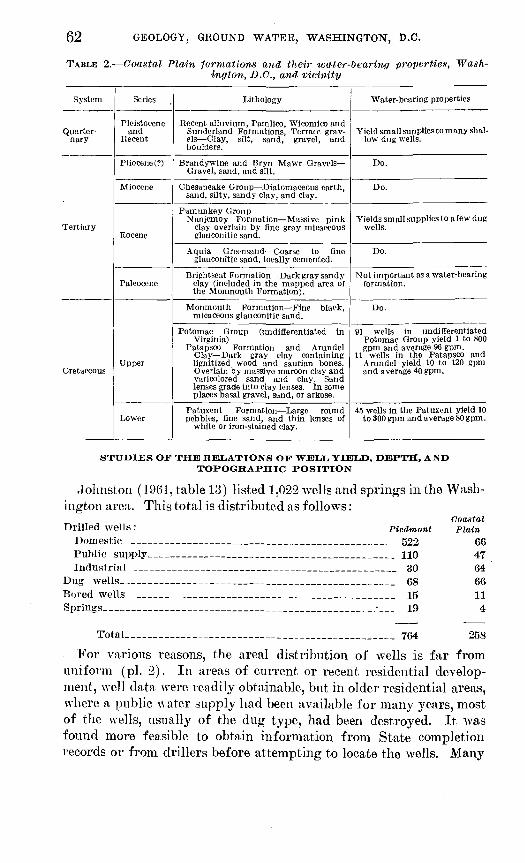
62 GEOLOGY, GROUND WATER, WASHINGTON, D.C.
TABLE 2. Coastal Plain formations and their water-tearing properties, Wash ington, D.C., and vicinity
System
Quarter- nary
Tertiary
Cretaceous
Series
Pleistocene and
Recent
Pliocene (?)
Miocene
Eocene
Paleocene
Upper
Lower
Lithology
Recent alluvium, Pamlico, Wicomico and Sunderland Formations, Terrace grav els Clay, silt, sand, gravel, and boulders.
Brandywine and Tiryn Mawr Gravels- Gravel, sand, and silt.
Chesapeake Group Diatomaceous earth, sand, silty, sandy clay, and clay.
Pamunkey Group Nanjemoy Formation Massive pink
clay overlain by flne gray micaceous glauconitic sand.
Aquia Greensand Coarse to fine glauconitic sand, locally cemented.
Brightseat Formation Dark gray sandy clay (included in the mapped area of the Momnouth Formation) .
Monmouth Formation Fine black, micaceous glauconitic sand.
Potomac Group (undiflerentiated in Virginia)
Patapsco Formation and Arundel Clay Dark gray clay containing lignitized wood and saurian bones. Overlain by massive maroon clay and varicolored sand and clay. Sand lenses grade into clay lenses. In some places basal gravel, sand, or arkose.
Patuxent Formation Large round pebbles, fine sand, and thin lenses of
white or iron-stained clay.
Water-bearing properties
Yield small supplies to many shal low dug wells.
Do.
Do.
Yields small supplies to a few dug wells.
Do.
Not important as a water-bearing formation.
Do.
91 wells in undiflerentiated Potomac Group yield 1 to 800 gpm and average 96 gpm.
11 wells in the Patapsco and Arundel yield 10 to 120 gpm and average 40 gpm.
45 wells in the Patuxent yield 10 to 300 gpm and average 80 gpm.
STUDIES OF THE RELATIONS OF WELL YIELD, DEPTH, AND TOPOGRAPHIC POSITION
Johnston (1961, table 13) listed 1,022 wells and springs in the Wash ington area. This total is distributed as follows:
Coastal Drilled wells: Piedmont Plain
Domestic _____ ________________________ 522 66Public supply__ _____________________ HO 47Industrial--_______________________________ 30 64
Dug wells__________________________________ 68 66Bored wells___________________________________ 15 11Springs _ _______._______________;__ 19 4
Total_________________________________ 764 258
For various reasons, the areal distribution of wells is far from uniform (pi. 2). In areas of current or recent residential develop ment, well data were readily obtainable, but in older residential areas, where a public water supply had been available for many years, most of the wells, usually of the dug type, had been destroyed. It was found more feasible to obtain information from State completion records or from drillers before attempting to locate the wells. Many
WATER RESOURCES 63
times in canvassing an area it was found that detailed information was not obtainable even when the well could be located. On the other hand, full data on dug wells generally could be obtained in the field. In areas where wells were scarce, particularly in the northwest part of the District, information from foundation borings was used.
In the following tables various comparisons are made between wells in the different formations, both in the Piedmont and in the Coastal Plain, although most of the statistical studies were made in the Pied mont drilled wells. The depth and yield of drilled wells in the Pied mont were compared among the several formations (table 3); the re lation of yield to depth is indicated in table 4; the relation of yield to depth of weathering is shown in table 5. The effect of topographic po sition on depth, casing, and yield is shown in table 6. Table 7 shows the relation of topographic position to depth of well and water level in dug or bored wells in both the Piedmont and the Coastal Plain. Table 8 compares the yields of wells in the principal water-bearing formations of the Coastal Plain.
Although the conclusions reached are logical, it is apparent that the comparisons are not necessarily valid for some formations because of the lack of sufficient samples. Furthermore, whereas the depth of well, length of casing, and depth to water level are reasonable ac curate, yields reported for domestic wells generally are inaccurate because of the testing procedures used.
DEPTH AND YIELD OF DBILLED WELLS IN THE PIEDMONT BY GEOLOGIC UNITS
Table 3 indicates that wells in the Piedmont have yields ranging from 0.2 to 110 gpm from wells 21 to 825 feet deep. Yields from wells of the Pimmit Service Corp. are 45 to 212 gpm from wells 337 to 741 feet deep. The average depth of wells in the Piedmont, exclusive of those of the Pimmit Service Corp., is 124 feet, the average yield 13 gpm. The average yield of Pimmit Service Corp. wells is 116 gpm.
Wells in formational contacts have the highest yields; they range from 5 to 40 gpm and average 16 gpm. Pimmit Service Corp. wells also are in formational contacts (of the Sykesville Formation and the overlying Wissahickon) and their yields as well as their depths are much greater than average 116 gpm and 550 feet, respectively.
The table indicates that wells in the Wissahickon Formation yield slightly more than the average of all wells in rocks of the Piedmont (excluding those in formational contacts) and that those in the Sykes ville Formation of Jonas, 1928, yield slightly less. Although wells in the Kensington Granite Gneiss of Cloos, 1951, and in the serpen tine are shown in table 3 to have low yields, these average yields may not be valid because of the small number of samples.
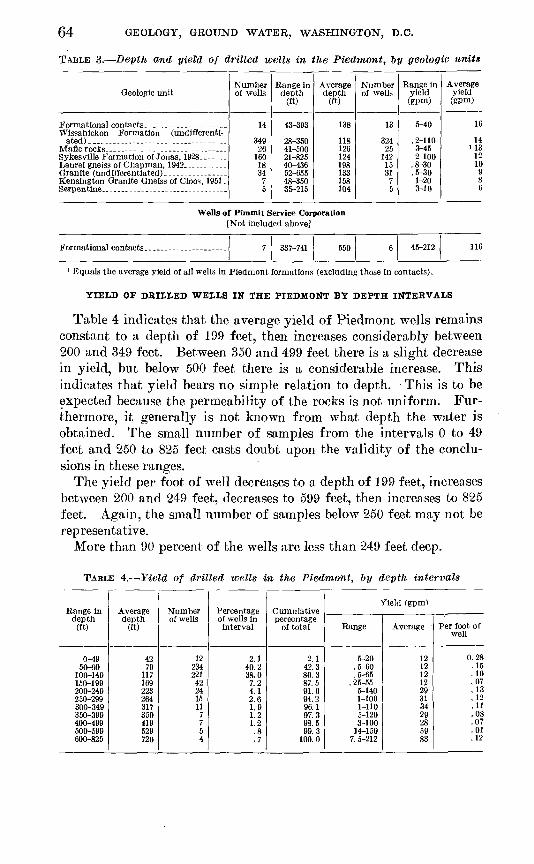
64 GEOLOGY, GROUND WATER, WASHINGTON, D.C.
TABLE 3. Depth and yield of drilled wells in the Piedmont, by geologic units
Geologic unit
Wissahickon Formation (undifferenti-
Eensington Granite Gneiss of Cloos, 1951 .
Number of wells
H
26160
1834
7
Range In depth
(ft)
43-393
28-35041-50021-82540-43652 65548-350 35-215
Average depth
(ft)
138
118126124198133158 104
Number of wells
13
32425
1421531
7 5
Range in yield fepm)
5-40
. 2-1103-45
.8-30
.5-301-20 3-10
Average yield (gPm)
16
14US
1210
98 6
Wells of Pimmit Service Corporation[Not included above]
7 550 45-212 116
1 Equals the average yield of all wells iu Piedmont formations (excluding those in contacts).
YIELD OF DRILLED WELLS IN THE PIEDMONT BY DEPTH INTERVALS
Table 4 indicates that the average yield of Piedmont wells remains constant to a depth of 199 feet, then increases considerably between 200 and 349 feet. Between 350 and 499 feet there is a slight decrease in yield, but below 500 feet there is a considerable increase. This indicates that yield bears no simple relation to depth. This is to be expected because the permeability of the rocks is not uniform. Fur thermore, it generally is not known from what depth the water is obtained. The small number of samples from the intervals 0 to 49 feet and 250 to 825 feet casts doubt upon the validity of the conclu sions in these ranges.
The yield per foot of well decreases to a depth of 199 feet, increases between 200 and 249 feet, decreases to 599 feet, then increases to 825 feet. Again, the small number of samples below 250 feet may not be representative.
More than 90 percent of the wells are less than 249 feet deep.
TABLE 4. field of drilled wells in the Piedmont, by depth intervals
Range Indepth
(ft)
0-4950-99
100-149150-199200-249250-299300-349350-399400-499500-599600-825
Averagedepth
(ft)
4279
117169223264317359419529720
Numberof wells
1223422142241511
7754
Percentageof wells in interval
2.140.238.07.24.12.61.91.21.2.8.7
Cumulativepercentage
of total
2.142.380.387.591.694.296.197.398.599.3
100.0
Yield (gpm)
Range
5-20.5-60.5-65
. 25-555-1401-1001-1105-1203-100
14-1507. 5-212
Average :
1212121229313429285983
Per foot of
well
0.28.15.10.07.13.12.11.08.07.01.12

WATER RESOURCES 65
RELATION OF YIELD OF DRILLED WELLS IN THE PIEDMONT TO DEPTH OFWEATHERING
In table 5 the length of the casing is a good indication of the depth of weathering. Dmgman and Meyer (1954, p. 32) concluded that the yield of wells in Montgomery County, Md., was related to the amount of weathered overburden on top of the hard rock. In the Washington, D.C., area an increase of yield with overburden depth (length of casing) seems to hold good to a depth of 99 feet, but below that depth fewer samples are available, and the figures may be mis leading. However, so many other factors affect the yield of a well that depth of weathering should not be the sole criterion.
TABLE 5. Relation of yield of drilled wells in the Piedmont to depth of weather ing (based on length of casing)
Length ofcasing (ft)
0-2425-4950-7475-99
100-124125-149150-174175-199200-238
Numberof wells
351401631003112
638
Averagelength ofcasing (ft)
20386185
112135163188215
Yield (gpm)
Range
0.2-30.3-110.5-120. 1-212
2.5-834-582-202-304-15
Average
913151716189
1210
RELATION OF DEPTH, CASING, AND YIELD OF DRILLED WELLS IN THE PIEDMONT BY TOPOGRAPHIC POSITION
Table 6 indicates that the amount of weathered overburden decreases on hilltops, uplands, hillsides, and spurs, in that order. In gullies, which are usually swept clean by rapidly moving water, the average overburden depth is considerably less. In valleys, the overburden may include both residual and transported materials (alluvium).
The average yields shown in table 6 appear to be in logical order. The lowest yields are from wells on hilltops and the highest from wells in gullies. The relatively high yield from wells on spurs is a little surprising, although it may be that most of these wells inter cepted zones of weakness dipping under the spurs from adjacent gullies.
Table 6 also indicates that it is usually necessary to drill deepest on uplands to obtain a satisfactory water supply. The next greatest depths are on hilltops, then on spurs. Hillsides and gullies require a.bout the same depths. The shallowest wells are in valleys.

66 GEOLOGY, GROUND WATER, WASHINGTON, D.C.
TABLE 6. Depth, casing, and yield of drilled wells in the Piedmont T>y topo graphic position
Depth of well
Topography
Hilltop--- -- --
Oully - _ ------Valley. - -
Number of wells
29 183 48
240 55
7
Average depth (ft)
122 144 120 111 110 94
Length of Casing
Number of wells
24 144 45
204 48 6
Average length (ft)
70 66 61 62 48 53
Yield
Number of wells
26 180 48
236 53
6
Average yield (gpm)
11 12 13 12 19 17
DUG AND BORED WELLS IN THE PIEDMONT AND COASTAL PLAIN RELATION OF DEPTH OF WELL AND WATER LEVEL TO TOPOGRAPHIC POSITION
As might be expected, table 7 indicates that it is best to place dug and bored wells where the water table is nearest the land surface. The water level is deepest in wells on spurs and shallowest in wells in gullies and valleys. The average depth of the wells decreases in like order (table 7).
TABLE 7. Dug and bored wells in the Piedmont and Coastal Plain relation of depth of well and water-level to topographic position
[Avg depth (weighted) of wells is 30.7 ft; avg depth (weighted) to water is 21.4 ft]
Topography
Hillside. . _. ------- ......
Valley. _ ...
Number of wells
86
6013
Average depth of well (ft)
34323120
Number of wells
86
5813
152
Average depth to
water (ft)
342622221010
YIELD OF DRILLED WELLS IN THE COASTAL PLAIN
The yields of the principal water-bearing formations in the Coastal Plain are compared in table 8. The Potomac Group is composed of the Patapsco and Arundel Clay and the Patuxent Formation. In Prince Georges County, Md., the Patapsco and Arundel have not been separated. In Virginia the Potomac Group is not differentiated. The table indicates that wells in the Patapsco and Arundel have an average yield of 40 gpm; in the Patuxent alone, 80 gpm; and in the undifferentiated Potomac Group, 96 gpm.
TABLE 8. yield of drilled wells in the Coastal Plain
Geologic formation Number of wells
11 45 91
Range (gpm)
10-120 10-3001-800
Average yield (gpm)
40 80 96

WATER RESOURCES 67
THE CHEMICAL CHARACTER OF THE GROUND WATER
By D. B. WEAVER and LEONARD Siu
The water-quality investigations in Washington, D.C., and vicinity were undertaken to provide current data on the quality of water in the several aquifers that would aid in developing and utilizing the ground-water resources, and to study the geochemical relations be tween water and the rocks in which it occurs.
Inasmuch as some water samples were taken from problem wells, that is, wells that produced water with high iron content or with cor rosive properties, the results show average water quality to be con siderably poorer than it actually is. This is especially true of the iron content, as many samples were taken because of iron problems.
Ground-water samples from 99 wells and 3 springs were analyzed and the results shown in table 9. The chemical and physical properties are summarized in table 10.
GEOCHEMISTRY OF GROUND WATER
Precipitation as rain or snow contains dissolved gases from the atmosphere, principally nitrogen, oxygen, and carbon dioxide. Upon contact with the earth, that part of the precipitation that infiltrates downward to the water table becomes ground water. In passing through the earth materials, the water takes up soluble constituents from the soil and weathered rock. Decaying organic matter in the soil releases carbon dioxide and organic acids to the water, thereby increasing its solvent power.
The principal constituents of ground water are bicarbonates, sul- f ates, and chlorides of the alkaline earths and the alkali metals. Other constituents generally present, but in smaller quantities, include silica, iron, manganese, copper, zinc, fluoride, nitrate, phosphate, and hydro gen sulfide.
Chemical and physical factors that affect the quality of water as it moves through the rocks include the geologic environment, the length of exposure time, and the processes of solution, oxidation, reduction, precipitation, and ion exchange. Ion exchange causes a change in the hardness of the water. Hardness is commonly thought of in terms of the soap-consuming property of the water and is attributable chiefly to the presence of calcium and magnesium; but free acid, heavy metals, and other alkaline-earth metals also affect the hardness. Some rock materials give up sodium ions in exchange for calcium and magnesium ions, thereby softening the water.
The chemical constituents of water are commonly reported in parts per million and equivalents per million; 1 nig (milligram) of solute in 1 kg (kilogram) of solution represents 1 ppm (part per million). Equivalents per million are computed by dividing parts per million of a constituent by its equivalent weight.

68 GEOLOGY, GROUND WATER, WASHINGTON, D.C.
TABLE 9. Chemical analyses of ground[In parts
Well
o
10
§R
1*0
sO>
p
£?
£
rt
*B S
OEM
8OD
3 '
g
SD
^
'p
s
0
o,o O
9"
oriN
"a
0
30
g,I 1
1
"3"
"Bo
CO
gB
so
PH
Wissahickon Formation albite-chlorite facies
FC-Aa-5FC-Aa-9____FC-Ac-6.......FC-Ac-7R-Ba-8...R-Bh-23 »______E-Bb-24 2...R-Bb-263. .R-Bc-1 2R-nc-2__.___R-Bc-9-_._____R-Bc-13-.--.R-Bc-18 '...._R-Bc-19 sR-nc-222_____R-Bc-24 '_-_.__R-Bc-272 .....R-I)c-28 >.R-Ca-1.. ..R-Ca-9.. ......R-Cb-3.. ......K-Ba-ls.......
10- 9-586-26-555-26-555-26-55
3- 7-513-27 513-27-511- 6-45
2- 2-569-26-5810-22-4112-27-463-28-519-28-543-28-513-27 51
5-26-55
4- 7-49
7828172
31784
137162
108
95102
173113147109135126110117
60
5758
55
58
2021
13261117101819
17
11
32
3516
0.0.0.2
.5
.5
.0
.51.1
.5
.0
.5
1.5
0.02oe
.10
09.00.20.10.16.00
2.3.14.04.02.20
.CO1.0.02.08.13.10
0.11.02.08
.00
.00
no
.15
.00
.05
.01
.6900.70
.02
.92
.48
.77
9.45.1
5.71.75.25.7A Q
2.0.7
384.3
1.88.2
4.09 16.85.8153.8
3.61.9
3 2
2.54.81, 61.51.0
201.8
3.63 3
4.53.82.82.19.1.5
3.84.06.04.03.3
7
1.8.04.6
5.0
'
7.5
9.0
1.6
2.6.31.0
2
.6
1.3
.8
2.75.02.0
Wissahickon Formation oligoclase-mica facies
K-Bb-8 -K-Bb-13.....K-Bb-19K-Bc-24-----.BT-Ba-3.......BT-Ha-6 __BT-Ba-7.. ..BT-Ba-11 . BT-Ba-16- _ . BT-Ba-17- ._BT-Bb-2......
2- 6-556- 2-5512-18-576- 2-556- 2-556- 2-55
6- 2-55 6-30-55 12-20-5712-23-52
646511110966618773 30
95
61
60
61
----- -
2625
246.17.3
135.6 268.1
0.1
1.0.8
.0
.3
.0
.2
34.02.012.61.3.26
.10
.02
.023.6
0.06.00.03.0001.55.00 .78 .07.06
0.46.03
.233.9
.20
.14
.80
276.05.44.61.62.0
1.7 5.6 2.51.4
2.32.5
.3
.8
.2
.8
9.35.5
5.31.21.2
2.7 3.5
2.9
2.41.1
1.6.7.8
i.i.2
1.0
Wissahickon Formation Undifferentiated
FC-Ba-27 ...FC-Bb-19----- FC-Bc-43- - FC-Ca-12 ... FC-Ca-!4-- _FC-Ca-17 --- FC-Ca-23.- ...FC-Ca-24 ...
FC-Cb-ll._...AN-Aa-8------AN-Aa-11 ....AN-Ab-9.-----AN-Ca-7.---..
12-19-5710- 1-58 10- 1-58 7-19-5fi 5-23-551-10-55 1-12-551-12-551-10-557-21-5410- 9-5810-11-54
7-21-55
140125 95 138 34196
160900
1636210610983
......
55 55
54
273114 16 1424
1 ft
2023
0.0.0 .1 .1
.0
.0
.0
.0
.83
.12 1.6 .21
12 1.82011
.02
.041.6.52
.05
.07
.09
.12
.00
.00
.00
.14
.08
.00
.38
.30
.76
.66
00
flQ
.00
3.0 5.1 2.4
5.8
3.45.85.6
3.212
4.42.1 2.3 3.5 1.14.0
o o
4.83.0
.66.1
6.1 4.6 4.6
5.
3
4.5136
13
0.6 1.5 .2
5
6
1.6
9.6
See footnotes at end of table.

WATER RESOURCES 69
water in Washington, D.C., and vicinity
per million]
da
3
0w3Oi
§
1s
6CO
3
CO
6
g 30
£
*
o
E
6fc^Tis 2
3
aPH
0
-^ oo
Sos
p>.s-5.o
Hardnessas CaCOs
ag"o?
3 8)
*o3 O O
3
.03
1
8 U5
E-" *o 03
0 n
oS
glo t» wa
^"3 0
3O
aRuoI8
Wissahickon Formation albite-chlorite facies
0.0.0. 1.0.0
.0
.1
.0
.0
fi.3370371656
8
34
23
4744
102
0.1. 1
22.2.1
14.3
2 1
.01.0
2.6
3.0.5
6.1.2
7.41.3
5.02.22.81.21.76.0
8.66.42.22.03.53.43.19.7.2
2240
1.24.54.1
0.2.1.0.1.1
.1
.2
. 1
.0
.0
.3
8.11.41.31.21.2.6
1.42.01.62.0
1.5.7
2.01.85.03.05.0.9
1.23.0.0
o.o.1.1.1.0
0
.0
.2
.0
8759
130633874
1221045824615540
8812290
1468875
13692
382167281024383121
6184
181417323828
28287517
40
1000
0
0
00
10166
173663388
23
69
56
9876
190
6.46.5636 86.56.16.1
605.96.56.36(17.35.85.85.85.86.26.86 963
0888
0
80
2717569.38.0
71
20
27
1.8
471120
Wissahickon Formation oligoclase-mica facies
0.2. 1
.....
.0
.0~~"b~
.1_____-----
121274041201913122131
8
41.1
3.8. 1.1. 1
2.2.1.1.0
1.2
152.31.71.71.81.8.6
1.23.0.8
3.2
0.1.0.1.0.0. 1
.1
.01
.0
0.15.01.01.21.81.84.51.85.81.06.3
0.0.1.0.0.0.1
.1
.0
.0
.0
1985868652829
33435537
1381723231615128
1811
7
390000020100
32165.570.769.436.434.440.033.853.150.436.5
6.26.27.56.86.66.46.16.2P. 46.55.6
528
1753
.... --
58
......
1527
2.108.
121612151635
Wiasahickon Formation Undifferentiated
o.o.0. i
.0
-----
6230173664465012345130232528
6.0.4.4.4.5
1.8.3
1.21.2.2
.64.8
1.02.05.52.52.51.82.02.5
4.04.05.02.434
0.2.2.2.0
.1
.2
.0
0.32.912
. 16.01.4
4.0.5.5
3.1
.615
0.0.1.1.1
.0
.1
8364674779
69
55157
37162223
31319
223426161155
0080
000
020032
1046079621278386346086747948196
8.06.66.16.46.S7.07.35.66.36.86.36.36.26.1
77210
000
5
0.1262123167.34.0302713248.8
2535
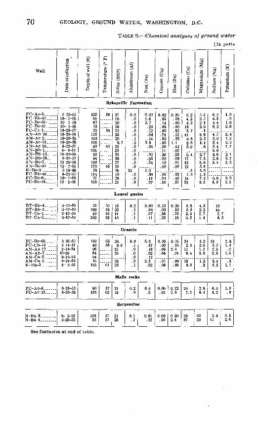
70 GEOLOGY, GROUND WATER, WASHINGTON, D.C.
TABLE 9. Chemical analyses of ground water[In parts
Well
."-§
*O
O
o
1 q
«? 3
&*o.flA aq
&
a3
! &o
1S
5
|,g
<
& §M
a0
<E>
1 o
Su.sN
O
a '3 3
0
^^
2
£1 1
2
Sodium
M
|
I
Sykesville Formation
FC-Ac-3 _ ..FC-Bb-57..
FC-Bc-57... ...FC-Ce-1. ...AN-Ab-20-. ..AN-Ac-2......AN- Ac-13 .. ..AN- Ac-16.-...AN-Bb-l--.-_AN-Bb-15. ..AN-Bb-28- .AN-Bc-7. .AN-Bc-31 _ ..K-Ba-2 .... ..FC Bb 40..FC-Bc-6 .___
10- 1-5810- 1-5810- 1-5810-23-5710-29-58
10-29-58
6- 5-5710-29-585-21-57
12- 7-585-18-499-21-55
10- 1-5810- 1-58
135656775
11510316683
2268594
100170
7811477
103
59
58
62
45
171Q
29223320
9 715233336272598
26
0.0.0.0.0.0.0.1.2.0
.0
.0
.0
.012
-0.0.0
0.071.62 7
oe
.04.14
3.8
.02
.34
1.600
17
0.02AQ
.08AA
.02no9A
.30
.00
.10
.00
.66
.04
.30
.58AA
AA
QO
.12qo
1.1.44.02.20.00.01.00
4007
8.2
4 f>165.7
8.63 n
6.4
15
.51 9
14Oq
5.52.52.19 Q
.13.82 51.4
2.77.38.65.6
1 37.48.5
6.54.34.4o o
4.55.03.43.48.04.60 Q
8.1
6.66.0
1.0.9
1 R
2.6
1.2
2.12.72.5
2.23.3
Laurel gneiss
BT-Bb-4... ..BT-Bb-5.. .. BT-Ca-1 ....
2-17-59 2-17-59 2-17-59 2-17-59
55 248 40
250
55 56 55 59
15 23 11 15
0.2 .2 .1 .1
0.00 .05 .07 .11
0.13 .00 .36 .23
0.29 .10 .23 .18
5.8 5.0 3.3 2.5
4.5 2.2 2.7 1.4
1944 2.7 6.5
Granite
FC-Bc-63._...FC-Cb-15 . ..AN-Aa-17._...AN-Ab-2. .....AN-Ca-2......AN-Ca-5....-K-Bb-3______._
5-26-552-14-572-18-5410-588-19-548-24-546- 2-55
1604098849416
125
6355
------
'"ei"
249.9
3129
2825
0.0.1.0.0.0.0.1
8.3.57.16.02.12
3.3.02
0.09.00.09.04
.01
.06
0.16.36
2.9.24
.00
.03
312.5119.4
136.0
5.32.61.23.6
1.2.3
102.77.33.8
5.48.5
2.31.4.2
1.6
.51.1
Mafic rocks
FC-AC-9.......FC-AC-10.. .
6-26-555-26-55
80135
5762
2119
0.2.9
0.5.3
0.09.02
0.722.0
247.5
2.86.4
6.04.2
1.0.8
Serpentine
H-Ba-3 ... .E-Ba-4........
6- 2-55 10335
5757
2128
0.1 0.01.32
0.00.00
0.302.4
2967
6230
5.415
0.52.6
See footnotes at end of table.
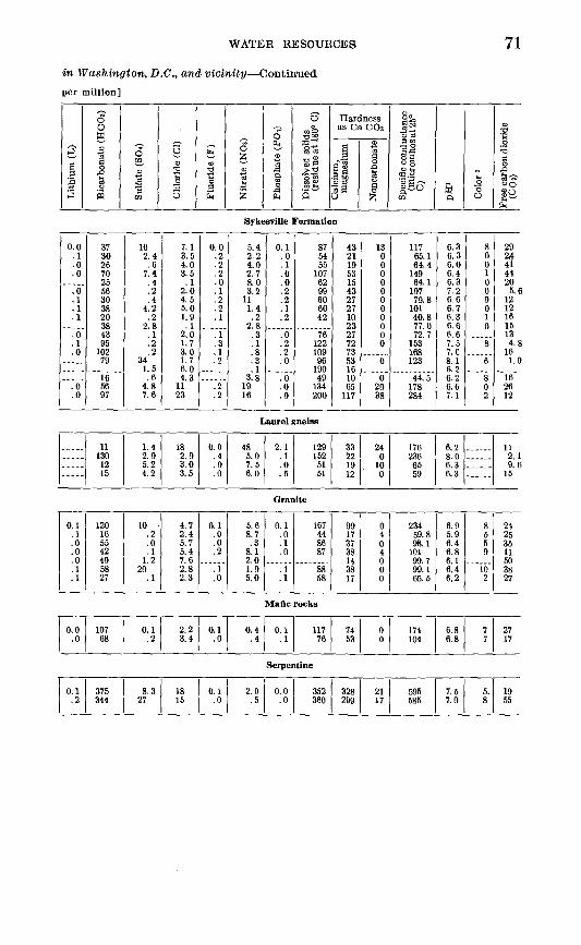
WATER RESOURCES 71
in Washington, D.C., and vicinity Continued
per million]
ss3
obonate (H
Sffl
6
"303
5
S 3 o
£ 1E
og,1crj
2
,^)hate (PO
Sg
0.-2.
Ived solids idue at 18(
M
Hardnessas Ca CDs
-1
6
sCJ§
J2
1
Si
0 C3
«I
81U (-.lle w
ft38
rbondioxi<
So |S
Sykesville Formation
0.0.1.0 .0
.0
.1
.1
.1
.0
.1
.0
.0
.0
37 30 26 70 25 56 30 38 20 38 43 95
102 79
1656 97
10 2.4 .6
7.4 .4 .2 .4
4.2 .2
2.8 .1 .2 .2
34 1.5 .6
4.8 7.6
7.1 3.5 4.0 3.5 .1
2.0 4.5 5.0 1.9 .1
2.0 1.7 3.0 1.7 6.0 4.3
11 23
0.0 .2 .2 .2 .0 .1 .2 .2 .1
.1
.3
.1
.2
.2
.2
5.4 2.2 4.0 2.7 8.0 3.2
11 1.4 .2
20.3 .1 .8 .3
3.8 19 16
0.1 .0 .1 .0 .0 .2 .2 .1 .2
.0
.2
.2
.0
.0
.0
.0
87 54 55
107 62 99 60 60 42
76 122 109 96
190 49
134 200
43 21 19 53 15 43 27 27 10 23 27 72 73 53 16 10 65
117
13 0 0 0 0 0 0 0 0 0 0 0
0
620 38
117 65.1 64.4
149 64.1
107 79.8
101 40.8 77.0 72.7
153 168 123
44.5 178 284
6.3 6.3 6.0 6.4 6.3 7.2 6.6 6.7 6.3 6.6 6.6 7.5 7.0 8.1
6.2 6.6 7.1
8 0 0 1 0 0 0 010
8
6
8 0 2
29
344 20
5.6 12 12 16 15 13 4.8
16 1.0
16 26 12
Laurel gneiss
-----
11 130 1215
1.42.0 5.2 4.2
18 2.0 3.0 3.5
0.0 .4 .0 .0
48 5.0 7.5 6.0
2.1 .1 .0.5
129 152
51 51
3322 19 12
24 0
10 0
176 236 65 59
6.2 8.0 6.3 6.3 ......
11 2.1 9.6
15
Granite
0.1.1.0.0.0.1.1
120165542405827
10.2.0.1
1.220
.1
4.72.45.75.47.62.82.3
0.1.0.0.2
.1
.0
5.68.7.3
8.12.01.05.0
0.1.0.1.0
.1
.1
167448687
8858
99173738143817
0404000
23459.898.1101QQ 7
99.165.5
6.95.96.46.86.16.46.2
8550
102
24253511503827
Mane rocks
0.0.0
10768
0.1.2
2.23.4
0.1.0
0.4.4
0.1.1
11776
7453
00
174104
6.86.8
77
2717
Serpentine
0.1 .2
375 344
8.3 27
18 15
0.1 .0
2.0 .5
0.0 .0
352 360
328 299
2117
595 585
7.5 7.0
5. 8
1955

72 GEOLOGY, GROUND WATER, WASHINGTON, D.C.
TABLE 9. Chemical analyses of ground water
[In parts
Well
ate of collectio
03
Q
£
epth of well (
Q
£
nperature (°
8 H
s*O in03 0
5
imiuum (Al)
5
?& OIM
aper (Cu)
o U
Io3N
cium (Ca)
03U
gnesium (Mj
§
ium (Na)
SOQ
ST
I
£
Potomac Group
AX-Ba-4....._
AX-Ac-l______AX-Ac-2._..._AX-Bb-9---_._AX-Bb-12___AX-Bc-4...._.AC-Bc-l_______
4-29-36
9- 8-37
8-24-533-49
130324
396325448630
211323
12
10
6.6
.0
.0
1.5.95
1.11.0.03.04.19.20
0.00
.02
6.66
.12
.00
18
16
.41.2
17
101.6
11
2.1.2.1
9.1
507.1
9.080 605.9
5.54.8
2.6.8
1.6
Patuxent Formation
WW-Bb-2.....WW-Ac-5_____WW-Cc-12,...WW-Cc-14 .WW-Cc-28....AX-Cc-6 - .WE-Ca-ll_____ BT-Bb-12.. .
4-24-58 2- 8-591- 5-383-13-58
3-503- 6-54 6- 2-55
Spring Spring
90127
290367 124
56
64 59
14
99
3330
19 7.1
0.0
.0
.1
.0
.0
.3
2.8 .10.02.16.10
1.34.3 1.4
0.00 .00
.00nn
.66
.00
0.00 .08.00.00.01
.10
.22
22 1.7
21QO
301.310 2.5
6.8 1.3
15112.0
6.6 .9
7.3
381311532.8 2.4
2.6 8
5.69.52.44.7 1.1
Miscellaneous
AN-Cc-73..... AX-Aa-18 3. .WE-Bb-6<___- FC-Ca-5»-._ BT-Bb-1 «___ AN-Bb-7' ..
0-29-54 11-20-504-24-58 0-24-54 7-26-55 8-28-57
29 1526 21 30 17
60
""63"
50 70
7.1 6.118 5.9
"l3""
0.1
.0
.0
.1
.0
0.07
.10
.26
.15
.10
0.00
.36
.08
.08
.23
2.2
.03
.36
.02
.00
7.6 47110 4.6 1.3 5.0
1.0 5.3
50 2.8 A
1.9
1.1
67 5.6 5.7 9.6
1.4
12 1.0
"l~.~8
1 Numerical units.3 Analyses by Maryland State Health Department.3 Alluvium and colluvium. Wicomico Formation.
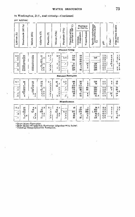
^ww
111
CO
-J
h-
_ _
^-
CO
O
00 O
os
CO
OS
tO
00
OO
i-'C
O)-'
h-
h-
Ci
CO
~J
O>
tO ~
J IO
O
O W
4k
SS
22
Oi
OS
OS
ps
^J O
S
OS
00 O
CO
WO
O
Oi
tO-J
h-I
O -
i !
! o
O 4
k|
to ^
i
i 1-
1
-j t
o to
4*.
H->
coO
O)-
'OW
O-J
OS
OO
tOW
-1 I
O i-1
tO
O
O ^
rfi.
-J
J
i -J
Qi
> 0
3
4^
O
O h
^ ^
-*
4k
OS
IOlO
;-1-4
4k
OT
4k
OO
W
OH
->O
CO
OO
OO
O^
-"
lA-
COw
w
-4 t
ow
o>
*-O
>tO
-q
i '
' O
o;
i o
>
oo
We
OO
~J
O~
-IO
iWt-
«O
OC
OC
OW
O-4
00
tO 2
Ui
W C
> £
0 C
O
. O
S C
D
OS
OS
1 4
k W
OW
-1
>
tOlO
CO
to
4
k *
- W
WW
-q
tO
^-"
to -g
co
*
to o
o *- C
O-J
O3Q
O *
- tO
O>
to-
i-*O
S O
| C
O O
*
W
i-1
tO
OS
IO
Osi-
1 4
k 4
k W
O U
i lO
Oi
o
& *fl
ormatior
i .
0
(& i
C
O W
i
O O
O
£co
oio
eo
eo
foeo
WlO
tOO
Oi-
'O'W
OS
tOtO
'-'t
Oh
-'-'
tO)-
' tO
OO
S4k|O
tO4kW
2H
-> ^
->
^->
O
SO
O
H-D
-"
OS
W
w
W
i O
Wi-
iO-J i
i-
1 H-
> W
i-1
IO
OlO
OS
tO'-
'O'-
'OO
O
11
1
i o
-
!' !
! '""'
!
w!
^^
to
^^
^
wc
o t
oco
co
en
w
oso
^-i
o
-g*.
§W
O^
OS
)-1
00
CO
tO
CO
CO
O W
OS
i O
O O
S i
tO I
OC
Oi-
>
tO
W W
-J
W
*
OS
W*-
W
OS
-IO
W*.^
WO
OC
O
i '
4k
OO
O O
O
w t
o j--
1-1
M w
MO
S i
-'O
OC
O
OS
)-'-
4
Lit
hium
(L
)
Bic
arbo
nate
(H
CO
a)
Sulf
ate
(SO
t)
Chl
orid
e (C
l)
Flu
orid
e (F
)
Nit
rate
(N
Os)
Pho
spha
te (
POO
Dis
solv
ed s
olid
s (r
esid
ue a
t 18
0° C
)
Cal
cium
, m
agne
sium
Non
carb
onat
e
CO M
01
W SI
Spec
ific
cond
ucta
nce
(mic
rom
hos
at 2
5°
C)
Col
or '
Free
car
bon
diox
ide
(CO
i)
2. 1
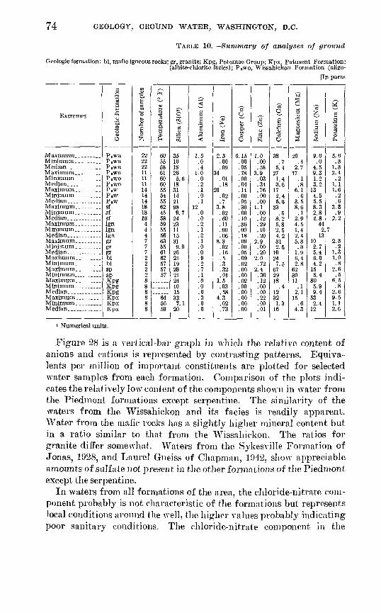
74 GEOLOGY, GROUND WATER, WASHINGTON, D.C.
TABLE 10. Summary of analyses of ground
Geologic formation: bi, mafic igneous rocks; gr, granite; Kpg, Potomac Group; Kpx Patuxent Formation;(albite-chlorite facies); P.wo, Wissahickon Formation (oligo-
[In parts
Extremes
Maximum _____
Median. ______
Maximum.
Minimum
Maximum _____
Maxim um_.___
Maximum. _ _
Median. ...
formation
'Mo 3O
P,wP W
P.wsfsfsf
bibisp
KpgKpgKpg
KpxKpx
of samples
1E&
22
2211
11
14
1818
4
7
2
2288
88
P4
V t-i _3
Temper
605558616060555455
585955
63
61
57
57
645659
i^O02
_aC£
&
351018265.6
1831
2198
9 724o*»
1101
9.926
1928
24101500
7.120
3e
Alumini
1.5.0
1.0
.1
.0
.112
.0
.0
.1
.0
.2
.0
.0
.0
.3
.0
.0
fc-
§ £
2.3.00.09
34.01.18
20.02.7
3.8.02.60
.06
.02
.5
.3
.32
.011.5
03.58
4.3.02
p Ul~l
I o O
0.15.00.05
70
.00
.00
.0530
.10
.0018
.05
.09
.00
.00
.02
.00
.00
.00
.00
.00
S-1ba
1.0.00.58
3 fJ
.03
.34
.00
.00
.00
.29
.10
.202 Q
.00
.202.0
2.4.30.12.00.00
.00
.01
'a
O.
Calcium
38.7
5.4271.43.6
2.45.6
OO
.5Q f)
K O
2 K
4.2q-i
2.510
7 c672918
1200
1.316
M
g
a3
Magnesi
20
2.717
.86.1
.03.58.6
2 94.51.42.45 0
1 96.42.8
62on
112.1
.64.3
"al
Sodium
9.0.0
4.59.31.23.2
134.55.58.32.84.8
442
1310
6.0
5.4805.9
532.4
g
EPotassiu
5.0.3
1.32.4
1.11.6.2
3.3.9
2.2
7
2.3.2
1.31.0.8
2.6.5
6.5.8
2.69.51.1
i Numerical units.
Figure 28 is a A-ertical-bar graph in which the relative content of anions and cations is represented by contrasting patterns. Equiva lents per million of important constituents are plotted for selected water samples from each formation. Comparison of the plots indi cates the relatively low content of the components shown in water from the Piedmont formations except serpentine. The similarity of the waters from the Wissahickon and its facies is readily apparent. Water from the mafic rocks has a slightly higher mineral content but in a ratio similar to that from the Wissahickon. The ratios for granite differ somewhat. Waters from the Sykesville Formation of Jonas, 1928, and Laurel Gneiss of Chapman, 1942, show appreciable amounts of sulfate not present in the other formations of the Piedmont except the serpentine.
In waters from all formations of the area, the chloride-nitrate com ponent probably is not characteristic of the formations but represents local conditions around the well, the higher values probably indicating poor sanitary conditions. The chloride-nitrate component in the

WATER RESOURCES 75
water in Wasliington, D.C., and vicinity
Ign, Laurel Gneiss; PiW, Wissahickon formation (undifferentiatecl); P«wa, Wissahiekon Formation clase-mica facics); sf, Sykesville Formation; sp, serpentine.per million]
3̂a5
H?
0.1.0.0.2.0.0.1.0.0.1.0.0
.1
.0
.1
.0
.0
.2.1.9.0.2.4.0.2
1So go§M5"
1028
40121
821641232
1021638
1301141
1201642
10768
3753441322899
1206
30
Oen
1u"3W
22.0.8
41.0.1
11.1.6
34.1
1.05.21.43.1
20.0
1.0.2
1278.3
241218
117.1
24
5"C
O
40.2
3.815
.61.8
34.2
2.523
.13.5
182.03.27.62.34.73.42.2
1815541.58.2
871.5
10
fe.o>
T3
O
fe
0.3.0.1.1.0.0.2.0.2.3.0.2.4.0.0.2.0.1.1.1.1.0.7.0.1.8.0.0
O55
155
8.1.0
1.56.3
.11.8
15.12
19.1
2.848
5.06.88.7.3
5.0,4.4
2.0.5
2.1.0.2
43.2
3.0
OfeS
1Sa
0.2.0.0.1.0.0.1.0.1.2.0.0
2.1.0.3.1.0.1.1.1.0.0.3.1.2.1.0.0
1
73 D"~
8 £005"""
1462481
1982849
1574768
2004287
1525190
1674486
11776
360352221
91136303
31160
Hardnessas CaCOs
,sBS5 2 2 SB'SO
1846
28138
71655
924
11710273312209914377453
32829986
239
1265
48
o 5«IO -^
55
1000
3900
3200
3800
240540000
211716
00
9306
o
llS so«~»S
i EJ^w
1902372
32134.450
1963479
28440.8
101236
59 120
23459.899
17410459558537413524635441.4
228
-
wa.
7.35.86.37.55.66.48.05.66.28.16.06.68.06.26.36.95.96.46.86.87.57.08.37.17.57.85.26.4
S"3O
804
1725
1004800
10057785
1000
2036
O gO
£1 a)
0.?
h
711.8
20352.0
1535
122441.0
16152.1
105011272717551911
.83.4
623.0
24
Coastal Plain formations is conspicuously large in the dug wells (AX-Aa-18 and AN-Bb-7) and in the spring (WW-Bb-2). In general, sulfate also is more prevalent in Coastal Plain ground water than water from the Piedmont. Waters from the Patuxent Forma tion and terrace deposits show larger quantities of the several com ponents indicated than that from any other formation in the area except serpentine.
aUALITY OF WATER IN RELATION TO SOURCE
The following discussion is based on analytical data for the follow ing geologic units: (1) Wissahickon Formation, (2) Sykesville For mation, (3) Laurel Gneiss, (4) Granite, (5) Mafic rocks, (6) serpen tine, (7) Potomac Group (undifferentiated), and (8) Patuxent Formation. Analyses of samples from two shallow wells obtaining water from both Coastal Plain sediments and the underlying bedrock also are included.
The first six units listed above are in the Piedmont province, the last two in the Coastal Plain province.
711-570 O - 64 - 6
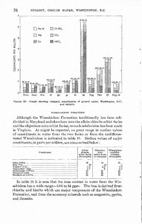
76 GEOLOGY, GROUND WATER, WASHINGTON, D.C.
ftwa ftwo ftw sp Kpg Kpx Qt Kpg-sf
FIGURE 28. Graph showing chemical constituents of ground water, Washington, D.C.,and vicinity.
WISSAHIOKON FORMATION
Although the Wissahickon Formation traditionally has been sub divided in Maryland and elsewhere into the albite-chlorite schist facies and the oligoclase-mica schist f acies, no such subdivision has been made in Virginia. As might be expected, no great range in median values of constituents in water from the two facies or from the undifferen- tiated Wissahickon is indicated in table 10. Median values of major constituents, in parts per million, are summarized below:
Constituent
Dissolved solids _ .
Albite- chlorite
schist facies (22 samples)
18
2.7408128
Oligoclase- mica
schist facies (11 samples)
1C
.183.6.8
21
16
Wissahickon (undifler- entiated:
14 samples)
.75.63.5
326824
In table 10 it is seen that the iron content in water from the Wis sahickon has a wide range 0.00 to 34 ppm. The iron is derived from chlorite and biotite which are major components of the Wissahickon Formation, and from the accessory minerals such as magnetite, pyrite, and ilmenite.

WATER RESOURCES 77
Iron-bearing minerals, when broken down by weathering processes, release soluble iron compounds, which, when leached from the over lying residual soils, may accumulate at the base of the weathered zone or in fractures in the rock. This is an oversimplified statement, but it helps explain the erratic range in iron content in water from meta- morphic and igneous rocks.
Water from wells R-Ca-1 and AN-Ca-7, 126 and 83 feet deep, contains 40 and 34 ppm of chloride, respectively, indicating possible polution. Nitrate in water from AN-Ca-7 was reported to be 15 ppm, also indicative of possible pollution. The maximum fluoride content of water from the Wissahickon is 0.3 ppm.
SYKESVILLE FORMATION OP JONAS, 1928
Ground water from the Sykesville Formation is represented by 18 samples (table 9). Median values for major constituents are in the same range as those for the Wissahickon Formation. Iron content ranges from 0.02 to 3.8 ppm; 9 samples contain iron in excess of 0.3 ppm, the maximum permissible limit under Public Health Service standards. One sample contained 12 ppm of aluminum, which is well above the normal range even with a pH of 6.2; no other water reported in the area contains more than 1.5 ppm of aluminum. The maximum flouride content of water from the Sykesville Formation was 0.3 ppm.
LAUREL GNEISS OP CHAPMAN, 1942
Four water samples were collected from wells in the Laurel Gneiss. Median values of the major constituents are in the same range as those of the Wissahickon, Sykesville, and granite formations. Iron ranges from 0.00 to 0.11 ppm, calcium from 2.5 to 5.8, magnesium from 1.4 to 4.5, bicarbonate from 11 to 130, dissolved solids from 51 to 152, and hardness from 12 to 33 ppm. The high nitrate content in BT-Bb-4, 48 ppm, is probably indicative of pollution. Flouride is at a maxi mum of 0.4 ppm.
GRANITE
Water from the granite is represented by seven samples. Median values of major constituents are in the same range of magnitude as those of the Wissahickson, Laurel, and Sykesville Formations. Iron ranges from 0.2 to 8.3 ppm, calcium from 2.5 to 31, bicarbonate from 16 to 120, dissolved solids from 44 to 167, and hardness from 14 to 99 ppm. Flouride was reported at a maximum of 0.2 ppm.
MAFIC ROCKS
Only two samples of water from mafic rocks were analyzed, both from greenstone. Among the major constituents, calcium, bicarbon-
78 GEOLOGY, GROUND WATER, WASHINGTON, D.C.
ate, and hardness had considerably higher average values than those of water froih the Wissahickon, Sykesville, granite, and Laurel Gneiss, whereas the other major constituents were in the same range of magni tude. Iron content ranges from 0.3 to 0.5 ppm, calcium from 7.5 to 24, magnesium from 2.8 to 6.4, bicarbonate from 68 to 107, dissolved solids from 76 to 117, and hardness from 53 to 74 ppm.
The comparatively low iron and magnesium content in water from rocks composed principally of ferromagnesian minerals may appear anomalous. However, some of these rocks are highly resistant to weathering, soils are commonly shallow, and consequently there is less opportunity for soluble compounds to form in the zone of weathering. But, inasmuch as only two samples are available upon which to base these conclusions, this inference is only speculative.
SERPENTINE
Only two water samples from the serpentine are available for analy sis. However, the water is readily distinguished from that from all other sources in the report area by its much higher content of dissolved solids, chiefly calcium, magnesium, and bicarbonate, and by its hard ness, which ranges from 299 to 328 ppm. Magnesium is a chief con stituent of serpentine, and calcium carbonate may be derived from calcite, which occurs in veins in the serpentine.
Iron content in water from the serpentine ranges from 0.01 to 0.32 ppm, calcium from 29 to 67, magnesium from 30 to 62, bicarbonate from 344 to 375, and dissolved solids from 352 to 360 ppm.
POTOMAC GROUP (UNDIFFERENTIATED)
The chemical character of the water from the Potomac Group is represented by samples from eight wells. Median values for calcium, bicarbonate, and sulfate are considerably higher than those from the Wissahickon Formation. Iron content ranges from 0.03 to 1.5 ppm, calcium from 0.4 to 18, magnesium from 0.1 to 11, bicarbonate from 28 to 132, and sulfate from 12 to 24 ppm. Fluoride content ranges from 0.0 to 0.7 ppm.
Water from wells AX-Bb-12, AX-Bc-4, and AC-Ba-4, all in the Potomac Group, contains disproportionate amounts of sodium salts, which suggests that water has passed through softening processes and is not representative of raw water from the Potomac Group. Sample AX-Bb-12 also shows 54 ppm of chloride, which indicates the possi bility of pollution. Water from Well AX-Bb-9 contains the second highest concentration of fluoride reported in the Washington area, 0.7 ppm.

WATER RESOURCES 79
PATTJXENT FORMATION
The Patuxent Formation is the lowermost formation of the Potomac Group and has been mapped separately in Maryland. Analyses of water samples from 6 wells and 2 springs from this formation are avail able. A comparison of median values of the principal constituents shows that the water is similar to that from the undifferentiated Potomac Group; the major difference is the lower concentration of bicarbonate which is 30 ppm compared to 99 ppm in water from the Potomac Group.
Iron has a median value of 0.73 ppm and a range of 0.02 to 4.3 ppm. Bicarbonate ranges from 6 to 120 ppm and dissolved solids from 31 to 303 ppm. Hardness has a median value of 48 ppm and ranges from 5 to 126 ppm.
An unusually high content of sulfate, 117 ppm, was reported in water from WW-Cc-14. Water from well WW-Cc-12 contained 87 ppm of chloride and 43 ppm of nitrate, indicating possible pollution. The nitrate content of water from WW-Bb-2 is 32 ppm, so much higher than the median of 3.0 ppm that it is considered suspect. In water from well WW-Cc-14, 0.8 ppm of fluoride was reported, the maximum in the Washington area.
QUALITY OF WATER IN RELATION TO USE
The ground water from sources in the Washington area is suitable, with some exceptions, for domestic, public, industrial, and irrigation purposes. Water-quality standards of the U.S. Public Health Serv ice (1946), as shown below, generally are used in determining the suitability of water for domestic purposes.
TABLE 11. Public Health Service standardsMaximum
recommended Constituents (ppm)
Iron and manganese (Fe and Mn) ______________ __. 0.3 Magnesium (Mg) _ ___ _ _.__. 125 Sulfate (SO,)_____ _______________________ 250 Chloride (01)____________________________.__. 250 Fluoride (F)____________________________.__ 1.5 Nitrate (NO3 )__ _ _________ _____ - *44 Dissolved solids (residue on evaporation at 180°C) 2 500 Zinc (Zn)__________________________________ 15 Copper (Cu) __________________ _ ___-__ 3.0 Phenolic compounds_-___ _ ._-__. . 001 Color (standard cobalt scale)._____ ___ Not to exceed 20 units. Turbidity (silica scale) ______ '. ___ Not to exceed 10 ppm.
1 National Research Council Bull. Sanitary Engineering, 1950.2 Desirable. 1,000 ppm permissible if better water not available.

80 GEOLOGY, GROUND WATER, WASHINGTON, D.C.
From table 9 it can be seen that several chemical constituents in \vater from the Washington area do not meet the U.S. Public Health standards. Iron content is excessive in approximately 40 percent of the samples, and nitrate exceeds the recommended limit in water from several sources. Free carbon dioxide, though not listed in table 11, can create a corrosion problem when present in excess of 10 ppm (Forbes, 1954). The high iron content is not surprising as the geologic formations sampled contain such minerals as chlorite, biotite, magne tite, ilmenite, and pyrite. These minerals contain iron in combination which is converted to soluble compounds by weathering or hydro- thermal processes. Inasmuch as some samples were collected expressly because of excess iron content, the iron problem appears to be much greater than it actually is. Nitrate in amounts exceeding recom mended limits is an indication of contamination and suggests local sur face seepage into the well.
The problem of hardness of water is of particular interest. Water having a hardness of less than 100 ppm generally is considered suitable for domestic purposes. Water having a hardness of 2 ppm or less is necessary in feed water for boilers operating at 400 psi (pounds per square inch) or more. Tolerances of process water vary from one industry to another and generally range from about 10 ppm to several hundred (California State Water Pollution Control Board, 1952, p. 265-267). From table 9 it can be seen that most of the water samples analysed have a hardness of less than 100 ppm. Obviously, water from most of the sources would require softening for use in high-pres sure boilers, although it would not be objectionable for many other industrial purposes.
Of the remaining chemical constituents and physical properties listed in table 9, only silica content gives cause for particular concern. It presents no problem for domestic use and most industrial uses, but it exceeds the recommended tolerance in boiler feed water for boilers operating at 400 psi or above. A limiting concentration of 0.1 ppm in the steam has been recommended by Minhoff (1948).
The problem of water quality is largely one of economics; if an adequate quantity of water is available, the quality can be adjusted to any given standard. Cost is the governing factor.
Many users have solved the problems caused by iron and other con taminants and by corrosiveness of the water by installing special treat ment units. The type of water-conditioning unit to be used depends upon the problem, which, in turn, is determined by a chemical analysis of the water and a knowledge of its physical properties. To combat corrosiveness, it is usually satisfactory to add a sufficient quantity of alkaline material to maintain the pH above 7.0 preferably 8.0 to 8.5 (Forbes, 1954, pt. 1, p. 126).

WATER RESOURCES 81
Ground water that has a high iron and nitrate content should have chemical treatment if it is to be used for domestic purposes. Con siderable quantities of nitrate in the water necessitate the investigation and elimination of possible sources of organic pollution.
SUMMARY
The study of the chemical characteristics of ground water from Washington, D.C., and vicinity indicates that the ground water gen erally is satisfactory for domestic, industrial and irrigation use. Water from most aquifers is soft to moderately hard 2 to 175 ppm. Water in the Piedmont province is dominantly of the calcium bicarbonate type; that in the Coastal Plain is of the calcium magnesium bicar bonate type. Dissolved solids range from 23 to 801 ppm and average 87 ppm. Salts of chloride and sulfate are present in the water from both provinces but they dominate in the Coastal Plain.
Iron was found in 90 percent of the samples analyzed. Forty per cent of the samples contained iron in amounts exceeding the recom mended permissible limit of the U.S. Public Health Service (0.3 ppm). In some of the water, a low pH, free carbon dioxide, and corrosiveness are troublesome.
Most of the water samples that contain zinc were resampled for verification. The zinc probably remains in solution because of an excess of bicarbonate and other acid salts. The solubility of zinc is likely to be controlled by the alkalinity of the water.
POTENTIAL, DEVELOPMENT OF GROUND-WATER RESOURCES
At the present rate of development there is no indication that deple tion of the area's ground-water resources will take place in the near future. Reports that shallow wells (less than 100 feet deep) have failed are heard during every drought, but deep wells continue to furnish water for public supply, industry and commerce, and private homes.
In the Piedmont, the ratio of withdrawal to potential yield is not known, but it is safe to say that only a fraction of the potential is now being utilized, except perhaps in local areas.
Although most wells in the Piedmont yield only a few gallons a minute, this quantity is sufficient for a private home and may be ob tained in most places. However, public supply wells in the Piedmont, notably those of the communities of Vienna and Pimmit Hills, yield as much as 212 gpm.
The city of Rockville, formerly supplied by ground water, in October 1958 began using water from the Potomac River. Seventeen of the city wells are kept, in service on a stand-by basis and are capable of supplying more than a million gallons per day.
82 GEOLOGY, GROUND WATER, WASHINGTON, D.C.
In the Coastal Plain, only the Potomac Group^ the Patapsco and Patuxent Formations are major aquifers in this area. Where these formations occur at sufficient depth and are of sufficient thickness, they are a copious and dependable ground-water source. There are many wells in the higher formations of the Coastal Plain, but in this area they are shallow bored or dug wells capable of furnishing only meager domestic supplies, and many are subject to failure in dry weather.
The mean annual precipitation in the Washington area is 41.65 inches. The recharge area of the Potomac Group is about 135 square miles. If 10 percent of the precipitation becomes recharge (a con servative estimate), nearly 27 mgd becomes available to wells. The daily withdrawal from these aquifers is estimated to be about 15 mgd, of which 5 mgd is for commercial or public use. Thus about 55 per cent of the available recharge is being withdrawn a reasonably favorable water balance. . Nevertheless, future large-scale development of ground water in the Coastal Plain in this area should be carefully controlled so that safe limits of withdrawal are not exceeded. Any such control, of course, would require cooperation between Maryland, the District, and Virginia. However, no large developments appear to be in prospect, except by the Washington Suburban Sanitary Com mission, which plans additional wells in the Fort Foote area.
If expansion of public supply and industrial well fields is necessary to keep pace with increased demands, adequate storage facilities and carefully controlled pumping schedules of adequately spaced wells will permit efficient utilization of the ground-water supplies. How ever, there is a limit to the amount of water that can be withdrawn, and, with today's high per capita demand, areas of high-density population and industrial expansion cannot be supplied indefinitely by local ground-water development.
Individual wells are necessary and economical for private dwellings on large lots (2 acres or more) or in semirural or rural areas, but a separate well for each home on a 100-foot lot is wasteful and inef ficient. Where coupled with individual sewage disposal units, indi vidual wells on small lots are especially vulnerable to pollution. A single well to serve several families, properly constructed, would be much more efficient and could be protected more readily against pollu tion. The problem then would become one of operation and main tenance; it probably would be necessary to organize a private-water company to operate the system, under present laws.
Overall, the present practice of using a major surface-water supply supplemented by ground water is the best plan for the future. Cer tainly the area's needs cannot be met by ground water alone. But wells are capable of supplying a substantial amount of water that
WATER RESOURCES 83
otherwise would run to waste. Furthermore, many parts of the area are still not served by the major public water systems and will continue to depend upon ground-water supplies.
In addition to using ground water as a supplemental public supply, the advantages of having a standby ground-water supply should be considered. Ground-water sources are not subject to destruction by natural causes or by enemy attack, including contamination by chemi cal, biological, or radiological poisoning agents. As an example, although the city of Eockville is now using a surface source, the Potomac River, it has preserved some of its wells for use in emergencies.
THE TRIASSIC BASIN
Although the Triassic basin lies a few miles west of the report area, development of ground water in 1959-60 at the Dulles Airport at Chantilly, Va., is mentioned here. In May 1959 two highly produc tive wells, 860 and 955 feet deep yielding 32Y and 600 gpm, were successfully completed in shale of Triassic age. In 1960 a third well was drilled to a depth of 1,030 feet and yielded 1,000 gpm. Until these wells were drilled, nothing had been known of the water-bearing properties of the deep Triassic rocks in this area, and this development indicates that large volumes of water still untapped may be available elsewhere in the Triassic rocks (Johnston, 1960).
However, chemical analyses of the water show that it is highly mineralized and very hard, containing excessive amounts of bicar bonate and sulfate. Although this water is reported to be satisfactory for drinking, it is probably unsuitable for some uses, and treatment might be difficult. A solution to the problem may lie in testing the water from various depths and localities in an effort to locate water of better quality.
FLUCTUATIONS OP GROUND-WATER I^EVEL
To determine the trend of ground-water levels and consequently potential ground-water supplies, the Geological Survey maintains many strategically located observation wells throughout the United States. Periodic measurements are made of the water levels in these wells, and the results are reported in water-supply papers published by the Survey.
Fourteen such observation wells are in the Washington, D.C. area. Several of the wells have continuous records dated from 1928 or 1930. But most have records of only a few years (Johnston, 1961, table 13). The Ross well at Rossyln, Va., has one of the longest records since 1928. The hydrograph of this well (fig. 29) is typical of water-table wells in this area.
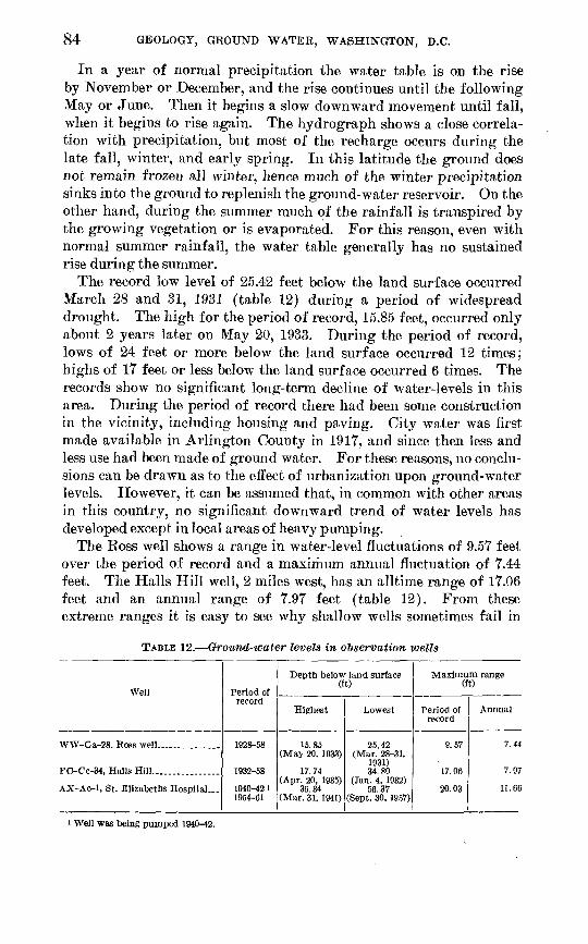
84 GEOLOGY, GROUND WATER, WASHINGTON, D.C.
In a year of normal precipitation the water table is on the rise by November or December, and the rise continues until the following May or June. Then it begins a slow downward movement until fall, when it begins to rise again. The hydrograph shows a close correla tion with precipitation, but most of the recharge occurs during the late fall, winter, and early spring. In this latitude the ground does not remain frozen all winter, hence much of the winter precipitation sinks into the ground to replenish the ground-water reservoir. On the other hand, during the summer much of the rainfall is transpired by the growing vegetation or is evaporated. For this reason, even with normal summer rainfall, the water table generally has no sustained rise during the summer.
The record low level of 25.42 feet below the land surface occurred March 28 and 31, 1931 (table 12) during a period of widespread drought. The high for the period of record, 15.85 feet, occurred only about 2 years later on May 20, 1933. During the period of record, lows of 24 feet or more below the land surface occurred 12 times; highs of 17 feet or less below the land surface occurred 6 times. The records show no significant long-term decline of water-levels in this area. During the period of record there had been some construction in the vicinity, including housing and paving. City water was first made available in Arlington County in 1917, and since then less and less use had been made of ground water. For these reasons, no conclu sions can be drawn as to the effect of urbanization upon ground-water levels. However, it can be assumed that, in common with other areas in this country, no significant downward trend of water levels has developed except in local areas of heavy pumping.
The Ross well shows a range in water-level fluctuations of 9.57 feet over the period of record and a maximum annual fluctuation of 7.44 feet. The Halls Hill well, 2 miles west, has an alltime range of 17.06 feet and an annual range of 7.97 feet (table 12). From these extreme ranges it is easy to see why shallow wells sometimes fail in
TABLE 12. Ground-water levels in observation wells
Well
WW-Ca-28. Eoss well...... . . .
FC-Cc-34, Halls Hill........ ......
AX-Ac-1, St. Elizabeths Hospital ...
Period of record
1028-58
1932-58
1940-42 1 1954-61
Depth below land surface (ft)
Highest
15.85 (May 20. 1033)
17.74 (Apr. 20, 1035)
36.34 (Mar. 31. 1041)
Lowest
25.42 (Mar. 28-31,
1031) 34.80
(Jan. 4. 1032) 56.37
(Sept. 30, 1057)
Maximum range (ft)
Period of record
0.57
17.06
20.03
Annual
7.44
7.07
11.66
i Well was being pumped 1940-42.

WATER RESOURCES 85
periods of drought. Water-level records of artesian wells in the Washington area are much less extensive than those of water table wells (fig. 29 and table 12). The longest continuous record, 1954-61, is for the well as St. Elizabeths Hospital in Ana'costia. A few meas urements were made in 1940^2, but the well was being pumped at that time and the record is of small value. However, the highest level was recorded during that period 36.34 feet below the land surface on March 31, 1941. The lowest level of record was 56.37 feet, Sep tember 30, 1957. Since 1957 the seasonal decline has been less each successive year. The reason for this is not clear but it may indicate cessation of pumping in nearby wells.
EMERGENCY WATER SUPPLIES
If public utilities, including water and power systems, were de stroyed during a nuclear war or other disaster, or if surface-water supplies were contaminated by radioactive fallout, wells and springs would become the only source of potable water.
Outside an area of total destruction it would be necessary to utilize undamaged wells and springs to the fullest extent and establish emer gency water-distribution points. Since public power would not be available, 110-220-volt portable power plants would have to be used to operate pumps. Hand pumps and pumps with independent power supplies, available for use in wells where the pumping equipment was inadequate or damaged, also would be desirable.
The present report describes the central part of the metropolitan area 436 square miles. Even if parts of this area were to be totally destroyed, many "wells and springs might remain intact or sustain only slight damage. These sources of water would be of vital importance in such an emergency.
Ground-water reports, including well inventories, are now available for only parts of the region adjacent to this report area. Ground- water reports discussing nearby Maryland have been published in recent years by the State in cooperation with the U.S. Geological Survey. (See Meyer, 1952; Dingman and Meyer, 1954; and Otton, 1955.)
Outside the present report area, the only recent ground-water infor mation in nearby Virginia is that pertaining to the Fairfax quadrangle (Johnston, 1962c). The remainder of Fairfax County and adjacent Loudoun and Prince William Counties have not been investigated for some time. Investigations in these counties should be made at an early date.
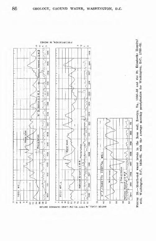
1 ' 1 '
'R
OS
S
WE
LL
/X'v
.
Vi""
'Xr-
1930
S
^
A ^
../"
\j
1931
1 '
A /
/ ^
. .-
1
:.!
1932
K\
./\ -\
KA
v
y M^ ; ;
./'V
\.'
;.-
1934
,,.,,,,
|^V
^ W
ate
r le
vel
\ V,
Pre
cip
ite :..V
* "
,. "
' ''i
J\ \
\tio
n
'"'' v
"'\..
.'
' i
/x/
X/N
'. .
S\:
"'
" .:'
\
1937
L/-\X
"M"
St
'-J-'
V
1938
1 '
l\
J X
Sta
tion L .
' ^ \''
'^
1939
1 '
/\
/ \
S W
B
' V
\.^
1940
' i
' |
1
'
/\
v-V
^>J
\ i
1941
P*
/ '
/V"
*\-
1942
1 '
'
l\
J \
VA
irport
L
' '"
'"'
.. /'
1943
1 '
'
,-^
J
X,
S W
B
,/v -
1944
to
14
0
16
1 »
-1
20
1
»U
2"
°
26
S 2s
n-
30
-. "
_1
' '
' '
RO
SS
W
EL
L
' N
/
!l
V
-- ^
^\
X
Na
tion
s.
,'/.
/ V
'\.
'x
1 A
irp
ort
\./
V\A
' ' r^
f ^
/ U S
W B
/\ A
V"'
"'
A, V
-Wa
\
ter
leve
l
'\ 1
'~'?
"'
1949
1
1950
/V\ \
V
ft.,-
-' W 1951
' ' A / \
/ \
,\,/
" \
i ' 19
55
' '
'
A/
\
\
V !... -
-..,
1953
^\
~~~^
v""v
-Vv
1954
s~
]~^
-/
."
./"*
'""
' v\
1955
' '
'
f\
^ X
.
I95S
' I
A ' \
..,.. .
. <
1957
r\ I \
1 \
' \
^f
' .
' ....
1958
' '
'
1959
oo o H
O O O
§ 1 a
tr LJ
<
40 45
50
55
60
ST
E
AS
\
\
National
V"V
AA'
1954
. ,
.
IZA
BE
TH
S
HO
/v
UV
1
^
SP
ITA
L
/ 1
\ /
^ P
recip
itation
\ /
Airp
ort
U S
W,B
/"-
-- '\
1955
t.^,..
'\.-.-
1956
V
......
,.^,~
..-19
57
WE
LL
//~
^J
f
. M
i-' v
-...
1958
A\ \
/\y
^,/
v X
-
1959
r^ ( \ \ ̂
.'V
V ~
..v
I96
0
/S
/ V
/J
.
1961
e h
FIG
URE
2
9. M
onth
-end
wat
er
leve
ls
in
the
Ros
s w
ell,
Eos
slyn
, V
a.,
1930
-58
and
the
St.
Eli
zabe
ths
Hos
pita
l w
ell,
Was
hing
ton,
D
.C.,
1954
-61,
w
ith
the
aver
age
mon
thly
pr
ecip
itat
ion
for
Was
hing
ton,
D
.C.,
1930
-61.
GEOLOGY, GROUND WATER, WASHINGTON, B.C. 87
SUMMARY AND CONCLUSIONS
Without an understanding of the diversified geology of the Wash ington area, the location of successful wells is a haphazard under taking. On opposite sides of the Fall Line, which roughly bisects the area from northeast to southwest, very different geologic conditions prevail; consequently, the rocks are very different in their water bearing properties. Northwest of the Fall Line, the Piedmont is underlain by deeply weathered igneous and metamorphic rocks; to the southeast, these rocks are buried beneath the sand, gravel, and clay of the Coastal Plain.
In the Piedmont, ground water occurs under unconfined or water- table conditions in openings or fissures in the rocks or in the weathered residual debris which lies upon them. Ground-water supplies for domestic use 5 to 10 gpm may be obtained in most places in the Piedmont. Wells yielding more than 200 gpm are known, but these yields are unusual, and the wells are in particularly favorable geologic localities. Careful location of wells with respect to the geology, includ ing the structure as reflected in the topography, generally increases the probability of obtaining higher than average yields.
In the Coastal Plain a knowledge of the subsurface geology is essen tial for the successful location of high-yield artesian wells. Only wells in the Potomac Group aquifers, at some distance downdip from the recharge area, are capable of yielding 300 to 800 gpm.
Observations of ground-water levels in the Piedmont part of the area for the last 30 years indicate no sustained downward trend of the water table. The present rate of ground-water withdrawal is not known, but only a fraction of the potential is being utilized, except in relatively small areas.
In the Coastal Plain part of the area, an estimated 15 mgd is being pumped from the aquifers in the Potomac Group. This is balanced against a conservatively estimated recharge averaging 27 mgd. This would indicate that about 55 percent of the available recharge is being withdrawn a reasonably favorable balance. Nevertheless, future large-scale development of ground water should be carefully planned.
If expansions of public-supply and industrial well fields are to keep pace with increased demands, adequate storage facilities and carefully controlled pumping schedules for adequately spaced wells will permit the most efficient utilization of ground-water supplies.
To provide for emergency water supplies in the Washington area, inventories of at least the major wells and springs should be made soon in the remaining parts of Fairfax County and all of Loudoun and Prince William Counties. Hand pumps and power units should be available so that wells may be utilized for emergency water sources.

88 GEOLOGY, GROUND WATER, WASHINGTON, D.C.
SELECTED KEFEKENCES
Agron, S. L., 1950a, Deformation in the Peach Bottom syncline: Am. Geophys. Union Trans., v. 31, no. 2, pt. 1, p. 262-260.
1050b, Structure and petrology of the Peach Bottom slate, Pennsylvania and Maryland, and its environment: Geol. Soc. America Hull., v. 61, no. 11, p. 1265-1306.
Alien, R. M., Jr., 1949, Virginia : geology unlimited: The Compass, v. 26, no. 3, p. 233-241.
Anderson, J. L., 1951, Metamorphism in Howard and Montgomery Counties, Maryland [abs.] : Am. Geophys. Union Trans., v. 32, p. 335.
Bascom, Florence, 1896, The ancient volcanic rocks of South Mountain, Pennsyl vania : U.S. Geol. Survey Bull. 136.
1902, The geology of the crystalline rocks of Cecil County [MarylandJ : Maryland Geol. Survey, p. 83-148.
1905, Piedmont district of Pennsylvania: Geol. Soc. America Bull. 16, p. 289-328.
1924, The resuscitation of the term Bryn Ma\vr gravel: U.S. Geol. Survey.Prof. Paper 132-H, p. 117-119.
Bascom, Florence, and others, 1909, Description of the Philadelphia district(Pa.-N.J.-Del.) : U.S. Geol. Survey Geol. Atlas, Folio 162.
Bascom, Florence, and Stose, G. W., 1932, Description of the Coatesville andWest Chester quadrangles, Pa.-Del.: U.S. Geol. Survey Geol. Atlas, Folio 223.
Bennett, R. R., and Collins, G. G., 1952, Brightseat formation, a new name forsediments of Paleocene age in Maryland: Washinglon Acad. Sci. Jour,, v. 42,no. 4, p. 114-116.
Berry, E. W., 1911, The correlation of the Potomac formations; Lower Cretaceous :Maryland Geol. Survey, p. 153-172.
Bertrand, K. J., 1952, Blue Ridge field trip, International Geog. Union, 8th Gen.Assembly and 17th Internat. Gong., Washington, D.C., Aug. 8-15, 1952: Natl.Geog. Soc., 25 p.
Billings, M. P., and Cleaves, A. B., 1935, Rrachiopods from mica schists, MountClough, New Hampshire: Am. Jour. Sci., 5th ser., v. 30, no. 180, p. 530-536.
Bloomer, R. O., 1939, Notes on the Petersburg granite: Virginia Geol. SurveyBull. 51-F, p. 137-145.
1950, Late pre-Cambriari or Lower Cambrian formations in central Vir ginia : Am. Jour. Sci., v. 248, no. 11, p. 753-783.
Bloomer, R. O., and Bloomer, R. R., 1947, The Catoctin formation in central Virginia : Jour. Geology, v. 55, no. 2, p. 94-106.
Bloomer, R. O., and Werner, H. J., 1955, Geology of the Blue Ridge region in central Virginia : Geol. Soc. America Bull., v. 66, no. 5, p. 579-606.
Brian, W. B., 1914, A history of the National Capital: New York, Macmillan Co.Brown, G. W., 1930, Washington A not too serious history: Baltimore, Norman
Pub. Co.Brown, W. R., 1953, Structural framework and mineral resources of The Vir
ginia Piedmont, in McGrain, Preston, ed., Proceedings of the Southeastern Mineral Symposium 1950: Kentucky Geol. Survey, ser. 9, Spec. Pub. 1, p. 88-111.
Burfoot, J. D., Jr., 1930, The origin of the talc and soapstone deposits of Virginia : Bcon. Geology, v. 25, no. 8, 805-826.

SELECTED REFERENCES 89
Cady, R. C., 1933, Preliminary report on ground-water resources of northern Virginia : Virginia Geol. Survey Bull. 41.
1938, Ground-water resources of northern Virginia: Viriginia Geol.Survey Bull. 50.
California State Water Pollution Control Board, 1952, Water quality criteria :pub. 3, 512 p.
Carr, M. S., 1950, The District of Columbia; its rocks and their geologic history :U.S. Geol. Survey Bull. 967.
Chapman, R. W., 1942, "Pseudomigmatite" in the Piedmont of Maryland : Geol.Soc. America Bull., v. 52 no. 9, p. 1299-1330.
Ch'ih, Chi Shang, 1950, Structural petrology of the Wissahickon schist nearPhiladelphia, Pennsylvania, with special reference to granitization: Geol.Soc. America Bull., v. 01, no. 9, p. 923-956.
Clark, W. B., 1897, Outline of present knowledge of the physical features ofMaryland, embracing an account of the physiography, geology, and naturalresources: Maryland Geol. Survey, v. 1, p. 139-228.
1915, The Brandywine formation of the Middle Atlantic Coastal Plain: Am. Jour. Sci., ser. 4, v. 40, p. 499-506.
Clark, W. B., and Martin, G. C., 1901, The Eocene deposits of Maryland: Mary land Geol. Survey, p. 21-92.
Clarke, F. W., 1924, The composition of the river and lake waters of the United States: U.S. Geol. Survey Prof. Paper 135.
Cloos, Ernst, 1937, The application of recent structural methods in the inter pretation of the crystalline rocks of Maryland: Maryland Geol. Survey [Rept.] v. 13, p. 27-105.
1948, Lineation A critical review and annotated bibliography: Geol. Soc. America Mem. 18.
1953, Lineation Review of literature 1942-1952; Geol. Soc. AmericaMem. 18 Supp.
Cloos, Ernst, and Anderson, J. L., 1950, Geology of Bear Island, Potomac River,Maryland: Johns Hopkins University Studies in Geology, no. 16, pt. 2.
Cloos, Ernst, and Broedel, C. H., 1940, Geologic map of Howard County andadjacent parts of Montgomery and Baltimore Counties, scale 1:62,500:Maryland Geol. Survey.
Cloos, Ernst, and Cooke, C. W., 1953, Geologic map of Montgomery County andthe District of Columbia, scale 1:62,500: Maryland Dept. Geology, Mines andWater Res.
Cloos, Ernst, and Hershey, H. G., 1936, Structural age determination of Piedmontintrusives in Maryland: Natl. Acad. Sci. Proc., v. 22, no. 1, p. 71-80.
Cloos, Ernst, and Hietanen, Anna, 1941, Geology of the "Martic overthrust" andthe Glenarm series in Pennsylvania and Maryland: Geol. Soc. America Spec.Paper 35, p. 139-185.
Cloud, P. E., 1936, The geological history of Washington, D.C.: Sigma GammaEpsilon, The Compass, no. 1, p. 105-111.
Cooke, C. W., 1931, Pleistocene changes of sea level [abs.] : Wash. Acad. Sci.Jour., v. 23, no. 2, p. 109-110.
1952, Sedimentary deposits of Prince Georges County and the Districtof Columbia, in Geology and water resources of Prince Georges County,Maryland : Maryland Dept. Geology, Mines and Water Res. Bull. 10, p. 1-53.
Cooke, C. W., and Cloos, Ernst, 1951, Geologic map of Prince Georges County,Maryland, and the District of Columbia, scale 1:62,500: Maryland Dept.Geology, Mines and Water Res.
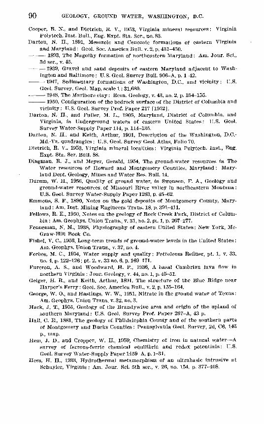
90 GEOLOGY, GROUND WATER, WASHINGTON, D.C.
Cooper, B. N., and Dietrich, R. V., 1953, Virginia mineral resources: VirginiaPolytech. Inst. Bull., Eng. Expt. Sta. Ser., no. 83.
Darton, N. H., 1891, Mesozoic and Cenozoic formations of eastern Virginiaand Maryland: Geol. Soc. America Bull. v. 2, p. 431-450.
1893, The Magothy formation of northeastern Maryland: Am. Jour. Sci., 3d ser., v. 45.
: 1939, Gravel and sand deposits of eastern Maryland adjacent to Wash ington and Baltimore: U.S. Geol. Survey Bull. 906-A, p. 1-42.
1947, Sedimentary formations of Washington, D.C., and vicinity : U.S. Geol. Survey, Geol. Map, scale 1: 31,680.
1948, The Marlboro clay: Econ. Geology, v. 43, no. 2, p. 154-155. 1950, Configuration of the bedrock surface of the District of Columbia and
vicinity : U.S. Geol. Survey Prof. Paper 217 [1952]. Darton, N. H., and Fuller, M. L., 1905, Maryland, District of Columbia, and
Virginia, in Underground waters of eastern United States: U.S. Geol.Survey Water-Supply Paper 114, p. 114-135.
Darton, N. H., and Keith, Arthur, 1901, Description of the Washington, D.C.-Md.-Va. quadrangles : U.S. Geol. Survey Geol. Atlas, Folio 70.
Dietrich, R. V., 1953, Virginia mineral localities: Virginia Polytech. Inst., Eng.Expt. Sta. Ser. Bull. 88.
Dingman, R. J., and Meyer, Gerald, 1954, The ground-water resources in TheWater resources of Howard and Montgomery Counties, Maryland: Mary land Dept. Geology, Mines and Water Res. Bull. 14.
Durum, W. H., 1956, Quality of ground water, in Swenson, F. A., Geology andground-water resources, of Missouri River valley in northeastern Montana:U.S. Geol. Survey Water-Supply Paper 1263, p. 45-62.
Emmons, S. F., 1890, Notes on the gold deposits of Montgomery County, Mary land : Am. Inst. Mining Engineers Trans. 18, p. 391-411.
Fellows, R. E., 1950, Notes on the geology of Rock Creek Park, District of Colum bia : Am. Geophys. Union Trans., v. 31, no. 2, pt. 1, p. 2G7-277.
Penneman, N. M., 1938, Physiography of eastern United States: New York, Mc-Graw-Hill Book Co.
Fishel, V. C., 1956, Long-term trends of ground-water levels in the United States:Am. Geophys. Union Trans., v. 37, no. 4.
Forbes, M. C., 1954, Water supply and quality: Petroleum Refiner, pt. 1, v. 33,no. 4, p. 122-126; pt. 2, v. 33 no. 6, p. 169-171.
Furcron, A. S., and Woodward, H. P., 1936, A basal Cambrian lava flow innorthern Virginia : Jour. Geology, v. 44, no. 1, p. 45-51.
Geiger, H. R., and Keith, Arthur, 1891, The structure of the Blue Ridge nearHarper's Ferry: Geol. Soc. America Bull., v. 2, p. 155-164.
George, W. O., and Hastings, W. W., 1951, Nitrate in the ground water of Texas:Am. Geophys. Union Trans. v. 32, no. 3.
Hack, J. T., 1955, Geology of tlie Brandywine area and origin of the upland ofsouthern Maryland: U.S. Geol. Survey Prof. Paper 267-A, 43 p.
Hall, C. E., 1881, The geology of Phildalephia County and of the southern partsof Montgomery and Bucks Counties: Pennsylvania Geol. Survey, 2d, C6, 145p., map.
Hem, J. D., and Cropper, W. H., 1959, Chemistry of iron in natural water Asurvey of ferrous-ferric chemical equilibria and redox potentials: U.S.Geol. Survey Water-Supply Paper 1459-A, p. 1-31:
Hess, H. H., 1933, Hydrothermal metamorphism of an ultrabasic intrusive atSchuyler, Virginia: Am. Jour. Sci. 5th ser., v. 26, no. 154, p. 377-408.
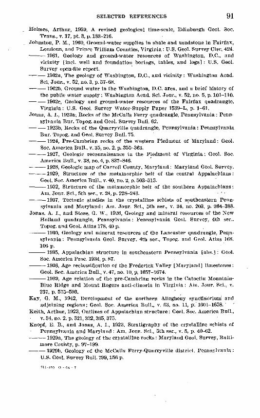
SELECTED REFERENCES 91
Holmes, Arthur, 1959, A revised geological time-scale, Edinburgh Geol. Soc.Trans., v. 17, pt. 3, p. 183-216.
Johnston, P. M., 1960, Ground-water supplies in shale and sandstone in Fairfax,Loudoun, and Prince William Counties, Virginia: U.S. Geol. Survey Circ. 424.
1961, Geology and ground-water resources of Washington, D.C., and vicinity [incl. well and foundation borings, tables, and logs] : U.S. Geol. Survey open-file report.
1962a, The geology of Washington, B.C., and vicinity: Washington Acad. Sci. Jour., v. 52, no. 3, p. 57-68.
1962b, Ground water in the Washington, B.C. area, and a brief history of the public water supply : Washington Acad. Sci. Jour., v. 52, no. 5, p. 101-110.
1962c, Geology and ground-water resources of the Fairfax quadrangle. Virginia: U.S. Geol. Survey Water-Supply Paper 1539-L, p. 1-61.
Jonas, A. I., 1923a, Rocks of the McCalls Ferry quadrangle, Pennsylvania : Penn sylvania Bur. Topog. and Geol. Survey Bull. 62.
1923b, Rocks of the Quarryville quadrangle, Pennsylvania : Pennsylvania Bur. Topog. and Geol. Survey Bull. 75.
1924, Pre-Cambrian rocks of the western Piedmont of Maryland: Geol. Soc. America Bull., v. 35, no. 2, p. 355-363.
1927, Geologic reconnaissance in the Piedmont of Virginia: Geol. Soc. America Bull., v. 38, no. 4, p. 837-846.
1928, Geologic map of Carroll County, Maryland: Maryland Geol. Survey. 1929, Structure of the metamorphic belt of the central Appalachians:
Geol. Soc. America Bull., v. 40, no. 2, p. 503-513. 1932, Structure of the metamorphic belt of the southern Appalachians:
Am. Jour. Sci., 5th ser., v. 24, p. 228-243. 1937, Tectonic studies in the crystalline schists of southeastern Penn
sylvania and Maryland: Am. Jour. Sci., 5th ser., v. 34, no. 203, p. 364-388.Jonas, A. I., and Stose, G. W., 1926, Geology and mineral resources of the New
Holland quadrangle, Pennsylvania: Pennsylvania Geol. Survey, 4th ser.. Topog. and Geol. Atlas 178, 40 p.
1930, Geology and mineral resources of the Lancaster quadrangle, Penn sylvania : Pennsylvania Geol. Survey, 4th ser., Topog. and Geol. Atlas 168. 106 p.
1935, Appalachian structure in southeastern Pennsylvania [abs.] : Geol. Soc. America Proc. 1934, p. 87.
1936, Age reclassification of the Frederick Valley [Maryland] limestones: Geol. Soc. America Bull., v. 47, no. 10, p. 1657-1674.
1939, Age relation of the pre-Cambrian rocks in the Catoctin Mountain-Blue Ridge and Mount Rogers anti-clinoria in Virginia : Aiii. .Tour. Sci., v.237, p. 575-593.
Kay, G. M., 1942, Development of the northern Allegheny synclinorium andadjoining regions: Geol. Soc. America Bull., v. 53, no. 11, p. 1601-1658.
Keith, Arthur, 1923, Outlines of Appalachian structure: Geol. Soc. America Bull.,v. 34, no. 2, p. 321, 322,365, 375.
Knopf, E. B., and Jonas, A. I., 1923, Stratigraphy of the crystalline schists ofPennsylvania and Maryland: Am. Jour. Sci., 5th ser., v. 5, p. 40-62.
1929a, The geology of the crystalline rocks : Maryland Geol. Survey, Balti more County, p. 97-199.
1929b, Geology of the McCalls Ferry-Quarryville district, Pennsylvania :U.S. Geol. Survey Bull. 799,156 p.
711-570 O - 64 - 7
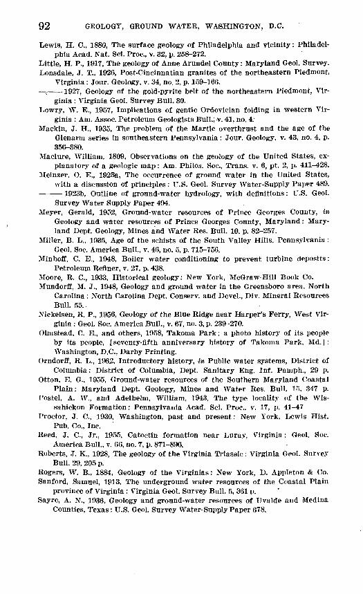
92 GEOLOGY, GROUND WATER, WASHINGTON, D.C.
Lewis, H. 0., 1880, The surface geology of Philadelphia and vicinity: Philadel phia Acad. Nat. Sci. Proc., v. 32, p. 258-272.
Little, H. P., 1917, The geology of Anne Arundel County: Maryland Geol. Survey.Lonsdale, J. T., 1926, Post-Cincinnatian granites of the northeastern Piedmont,
Virginia : Jour. Geology, v. 34, no. 2, p. 159-166. 1927, Geology of the gold-pyrite belt of the northeastern Piedmont, Vir
ginia : Virginia Geol. Survey Bull. 30.Lowry, W. B., 1957, Implications of gentle Ordoviclan folding in western Vir
ginia : Am. Assoc. Petroleum Geologists Bull.; v. 41, no. 4.Mackln, J. H., 1935, The problem of the Martlc overthrust and the age of the
Glenarm series in southeastern Pennsylvania: Jour. Geology, v. 43, no. 4, p. 356-380.
Maolure, William. 1809, Observations on the geology of the United States, ex planatory of a geologic map: Am. Philos. Soc., Trans. v. 6, pt. 2, p. 411 428.
Meinzer, O. E., 1923a, The occurrence of ground water in the United States, with a discussion of principles: U.S. Geol. Survey Water-Supply Paper 489.
1923b, Outline of ground-water hydrology, with definitions: U.S. Geol.Survey Water Supply Paper 494.
Meyer, Gerald, 1952, Ground-water resources of Prince Georges County, inGeology and water resources of Prince Georges County, Maryland: Mary land Dept. Geology, Mines and Water Res. Bull. 10, p. 82-257.
Miller, B. L., 1935, Age of the schists of the South Valley Hills, Pennsylvania :Geol. Soc. America Bull., v. 46, no. 5, p. 715-756.
Minhoff, C. E., 1948, Boiler water conditioning to prevent turbine deposits:Petroleum Refiner, v. 27, p. 438.
Moore, R. C., 1933, Historical geology: New York, McGraw-Hill Book Co. Mundorff, M. J., 1948, Geology and ground water in the Greensboro area. North
Carolina: North Carolina Dept. Conserv. and Devel., Div. Mineral ResourcesBull. 55.
Nickelsen, R. P., 1956, Geology of the Blue Ridge near Harper's Ferry, West Vir ginia : Geol. Soc. America B'ull., v. 67, no. 3, p. 239-270.
Olnistead, C. E., and others, 1958, Takoma Park; a photo history of its peopleby its people, [seventy-fifth anniversary history of Takoma Park, Md.]:Washington, D.C., Darby Printing.
Orndorff, R. L., 1962, Introductory history, in Public water systems, District ofColumbia: District of Columbia, Dept. Sanitary Eng. Inf. Pamph., 29 p.
Otton, E. G.. 1955, Ground-water resources of the Southern Maryland CoastalPlain: Maryland Dept. Geology, Mines and Water Res. Bull. 15. 347 p.
1'ostel, A. W., and Adelhelm, William, 1943, The type locality of the Wis-sahlckon Formation: Pennsylvania Acad. Sci. Proc., v. 17, p. 41-47
Proctor, J. C., 1930, Washington, past and present: New York, Lewis Hist.Pub. Co., Inc.
Reed, J. C., Jr., 1955, Catoctin formation near Luray, Virginia: Geol. Soc.America Bull., v. 66, no. 7, p. 871-896.
Roberts, .1. K., 1928, The geology of the Virginia Triassic: Virginia Geol. SurveyBull. 29, 205 p.
Rogers, W. B., 1884, Geology of the Virginias: New York, D. Appleton & Co. Sanford, Samuel, 1913, The underground water resources of the Coastal Plain
province of Virginia : Virginia Geol. Survey Bull. 5, 361 p. Sayre, A. N., 1936, Geology and ground-water resources of Uvalde and Medina
Counties, Texas: U.S. Geol. Survey Water-Supply Paper 678.
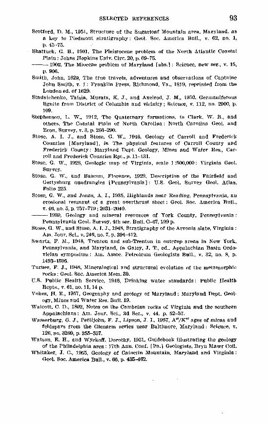
SELECTED REFERENCES 93
Scotford, D. M., 1951, Structure of the Sugarloaf Mountain area, Maryland, as a key to Piedmont stratigraphy: Geol. Soe. America Bull., v. 62, no. 1, p. 45-75.
Shattuck, G. B., 1901, The Pleistocene problem of the North Atlantic Coastal Plain: Johns Hopkins Univ. Circ. 20, p. 69-75.
-1902, The Miocene problem of Maryland [abs.] : Science, new ser., v. 15,p. 906.
Smith, John, 1629, The true travels, adventures and observations of CaptaineJohn Smith, v. 1: Franklin Press, Richmond, Va., 1819, reprinted from theLondon ed. of 1629.
Stadnichenko, Taisia, Murata, K. J., and Axelrod, J. M., 1950, Germaniferouslignite from District of Columbia and vicinity; Science, v. 112, no. 2900, p.109.
Stephenson, L. W., 1912, The Quaternary formations, in Clark, W. B., andothers, The Coastal Plain of North Carolina : North Carolina Geol. andEcon. Survey, v. 3, p. 266-290.
Stose, A. I. J., and Stose, G. W., 1946, Geology of Carroll and FrederickCounties [Maryland], in The physical features of Carroll County andFrederick County: Maryland Dept. Geology, Mines and Water Res., Car- roll and Frederick Counties Rpt, p. 11-131.
Stose, G. W., 1928, Geologic map of Virginia, scale 1:500,000: Virginia Geol.Survey.
Stose, G. W., and Bascom, Florence, 1929, Description of the Fairfield andGettysburg Quadrangles [Pennsylvania] : U.S. Geol. Survey Geol. Atlas,Folio 225.
Stose, G. W., and Jonas, A. I., 1935, Highlands near Reading, Pennsylvania, anerosional remnant of a great overthrust sheet: Geol. Soc. America Bull.,v. 46, no. 5, p. 757-779; 2031-2040.
1939, Geology and mineral resources of York County, Pennsylvania:Pennsylvania Geol. Survey, 4th ser. Bull. C-67,199 p.
Stose, G. W., and Stose, A. I. J., 1948, Stratigraphy of the Arvonia slate, Virginia :Am. Jour. Sci., v. 246, no. 7, p. 394-412.
Swartz, F. M., 1948, Trenton and sub-Trenton in outcrop areas in New York,Pennsylvania, and Maryland, in Galey, J. T, ed., Appalachian Basin Ordo-vician symposium: Am. Assoc. Petroleum Geologists Bull., v. 32, no. 8, p.1493-1595.
Turner, F. J., 1948, Mineralogical and structural evolution of the metamorphicrocks : Geol. Soc. America Mem. 30.
U.S. Public Health Service, 1946, Drinking water standards: Public HealthRepts., v. 61, no. 11,14 p.
Vokes, H. E., 1957, Geography and geology of Maryland: Maryland Dept. Geol ogy, Mines and Water Res. Bull. 19.
Walcott, C. D., 1892, Notes on the Cambrian rocks of Virginia and the southernAppalachians: Am. Jour. Sci., 3d Ser., v. 44, p. 52-57.
Wasserburg, G. J., Pettijohn, F. J., Lipson, J. I., 1957, A"/K" ages of micas andfeldspars from the Glenarm series near Baltimore, Maryland: Science, v.126, no. 3269, p. 355-357.
Watson, E. H., and Wyckoff, Dorothy, 1951, Guidebook illustrating the geologyof the Philadelphia area: 17th Ann. Conf. [Pa.] Geologists, Bryn Mawr Coll.
Whitaker, J. C., 1955, Geology of Catoctin Mountain, Maryland and Virginia :Geol. Soc. America Bull., v. 66, p. 435-462.
94 GEOLOGY, GROUND WATER, WASHINGTON, D.C.
White, G. W., 1952, Thomas Harlot's observations on American geology in 1588 [Va.]: Illinois State Acad. Sci. Trans., v. 45, p. 116-121.
1953, Geological observations of Captain John Smith in 1607-1614: Il linois State Acad. Sci. Trans., v. 46, p. 124-132.
White, W. A., 1952, Post-Oretaceous faults in Virginia and North Carolina: Geol. Soc. America Bull., v. 63, no. 7, p. 745-747.
White, W. F., 1949, Chemical quality of industrial surface waters of Pennsyl vania : Western Pennsylvania Engineers Soc: 10th Ann. Water Conf. Pitts burgh, Oct. 17-19, 1949, Proc., p. 143-153.
Williams, G. H., 1892, The volcanic rocks of South Mountain in Pennsylvania and Maryland: Am. Jour: Sci., v. 44, 3d ser., p. 482-496.
Williams, G. H., Darton, N. H., and Keith, Arthur, 1901, Description of the Washington, D.C.-Md.-Va. quadrangles: U.S. Geol. Survey Geol. Atlas, Folio 70.

INDEX
Page - S - 51_- _._ _- 49 ....... 28 . . 41............. 34.. ._ 62. --. - 33. . .. 42. .-.-- 54. ...- 85 31 - .-- 41
hydrologio properties... ... 62
B
Bear Island Granodiorite, exposure. - 24hydrologio properties. 61
Belvoir Reservoir ,_ - 52Bored wells, number.,__ .--... 62Brandywine Gravel, description_ 37
hydrologio properties- - -- 62Brightseat Formation, description__- --- 33
hydrologic properties -............. -- 62Bryn Mawr Gravel, section..- '.. 36
Acknowledgments.........Alexandria Reservoir . . Alexandria Water Co_....Aplite... ...................Aquia Greensand, dip .
fossils... -.- ....hydrologic properties.-lithology and extent -.
Arlington Spring...-- .. Artesian wells, Piedmont...
records...-.__._.-.. Arundel Clay, description..
dip...
Cable-tool drilling . ..._._...__ Cable-tool rig- ..._,___.__ Caffrey's Spring_...- _.________ Calvert Formation_-_-_-___I_-_ Carroll Springs-.- .._._._.. Chemical analyses._-______."_.'__. Chesapeake Formation _---___........Chesapeake Group, hydrologic properties_--
section.,...,..' ..-_.._.________ Choptank Formation ___------__-Clark, W. B., quoted _-.Cllmate.. -__-_ '........ -____....'.....Coastal Plain,aquifers._ __ ..._-
geologic formations_ -__-... hydrologlc properties- :
wells, withdrawal from...................yield. -_ -- -
C'olluvium_.____________ .1....Congressional Spring_-__-____-._-Cooke, C. W., quoted..:.--- 32,33,34,35,36, Cool Spring.. ... _____....Custis Spring. .-.. .....____.___...
DDalecarlla Reservoir..._ Drilled wells, number. ... Dug wells, number__ -.
5656443543683562353531
782
29,416287
46
EEconomic development..... Emergency water supplies.. Eocene Series............ ...
Page
88633
Fairfax County Water Authority _ - ___ - 49Fall Line.__... _ 5,9Faulting__..... - .--- 11Federal Spring... .-.- -... . 44Fossils, Patuxent- -. 29
O
4633g
70 61 77 24 21 74 67 67 54 83
Geography.-. . ................Geologic history .- Geology.. Georgetown Reservoir.. .- Glauconite...-- - - ... Gold...- .- ..............Granite, analysis of water from...............
hydrologic properties- - .......quality of water in_....... ......
Granitic rocks, cycles of intrusion-----........lithology and extent.. .......
Ground water, chemical analyses, summary.. chemical character__.. . .. .. constituents. . __ __ development.. ....fluctuations. .. . . iron content ..---...- ..-- 59,80 movement-_ . - ... 63 occurrence, crystalline rocks.. - 52
sedimentary rocks- . - 54 quality---- -- 67
related to source.........., ......... 75related to use. . ..--. _.. 79
resources, future development---------. -- 81
Hardness-- _-_ .. . 67,80 Hotel Spring--- ---_. .. . 44 Hume Spring. -- . . 42 Hydrographs . , 86 Hydrologic cycle-.-._ ... . . 50
Introduction,-. . .. 2Ion exchange_ ____... ... 87Iron in ground water. ___..-,.. , 80
Joint system. Jurassic....
6011
95
96 INDEX
Kensington Granite Gneiss, exposure. - 24,63 hydrologic properties__ _...-.
Lake Barcroft..-_ . -_---__. Laurel Gneiss, analysis of water from.
hydrologic properties..- ---..,-.lithology and extent.. . .quality of water in. ...
Location of the area.. __......._...Lower Cretaceous Series.... . .....Lower Paleozoic(?) rocks... .
MMcMillan Reservoir_ ...Mafic rocks, analysis of water from.,
hydrologic properties.. - lithology and extent....- . quality of water in.... , .
Magothy Foundation, description... dip. . .
Major aquifers_ .... ...Maryland, public water supply__.Miocene Series... ...Monmouth Formation, description-
dip.- . ....... ._ ...hydrologic properties..... ...
N
Nanjemoy Formation, description., dip..-_.-..__...______.. hydrologic properties.,.-.- .
Occoquan Granite -- Orndorff, R. L., quoted.
Paleocene Series -- ......Pamlico Formation, description..............
hydrologic properties.....................Pamunkey Group, division_ _--_.-.......
hydrologic properties. ... --- Patapsco Formation, dip. ................
fossils. - hydrologic properties . .....lithology and ex tent.... section-.... _--- . .
Patuxent Formation, analysis of water from.. dip.. ..- hydrologic properties.---....-_.__......lithology and extent.-..--. . --quality of water in . _ section... -
Peters Creek Formation.-__ .. -- Piedmont, geologic formations--- -- ...
geologic formations, hydrologic properties.structure-..
wells, depth and yield by geologic forma tion.....
yield by depth.....-..--. ........yield by depth, casing, topographic
position.... . -yield by depth.of weathering....... -
Page
24,63 61
51 70 61 16 77 3
29 11
47 70 81 14 77 32 41 82 49 36 32 41 62
3441 62
2445
33 39 62 33 62 41 32 62 31 35 72 41 62 29 79 30 19 11 61 27
63 64
6565
Q
R
Recent alluvium and colluvium, hydrologic
S
Sykesville Formation, analysis of water from..
T
U Upper Cretaceous series.. .
Page 38 3647 72 29 62 78 51
7 3
79 2
24 40,60
38
41 62
61 82 49 56
35 60 88 70 61 14 78 80 42 45
7 55,62
45 51
27,41 87 38 62
6 51 70 17 61 77
43 7
62 33
6 60 83
31

INDEX 97
Virginia, public water supply..._______ 49
Washington Spa Springs-_. . . ........ 43Water resources....- - Water supply in District of Columbia, history.
present status..____.... .____Wells, construction methods.... ....
numbering system___ _. . __ observation, levels in. . Piedmont, depth and yield by geologic for
mation... yield by depth..... . ... . 64yield by depth of weathering... _
Piedmont and Coastal Plain, yield rela tions_.. _._ __
ge
49
434?4?486fl55
84
636465
88
Wells Continued
types... ..... ..... . ....
Y Young's Soring _ ... ...... ....
6962
606256386210681361117663
46
o

The U.S. Geological Survey Library has cataloged this publication as follows :
Johnston, Paul McKelvey, 1908-
Geology and ground-water resources of Washington, D.C., and vicinity. With a section on Chemical quality of the water by D. E. Weaver and Leonard Siu. Washington, U.S. Govt. Print. Off., 1964.. .
vi, 96 p. illus., maps (part fold., 1 col., part in pocket), diagrs., tables. 24 cm. (U.S. Geological Survey. Water-supply paper 1776)
Bibliography: p. 88-94.
(Continued on next card)
Johnston, Paul McKelvey, 1908- Geology and ground- water resources of Washington, D.C., and vicinity. 1964. (Card 2)
1. Geology Washington, D.C. 2. Geology Maryland- Washington, D.C. region. 3. Geology Virginia-Washing ton, D.C. region. 4. Water-supply Washington, D.C. region. 5. Water, Underground Washington, D.C. region. 6. Water Composition. I. Weaver, DeForrest E 1916- II. Siu, Leonard, 1927- (Series)

UNITED STATES DEPARTMENT OF THE INTERIOR GEOLOGICAL SURVEY
77° 15'00" 39° 05'00"
12'30"
?T«V I"? .\-^p-i-V V/ V L / x
OteP#*V?52
> ^^^^^^MT »-,. ^- . T^=^M'TJ'C^-<.S\ -«-"- .-. -%-»3.1^^- /^f^M-/ ^g ,,.- W - ^ - %/rf^^ ^f .. - .-LH«^' Kjgv^a^
"v.^
: A^ >>./*' sINTERIOR GEOLOGICAL SURVEYj^fl^HINGTON. D. C. W63O85
39-05'00"EXP LANATION
ALLUVIUM AND COASTAL-PLAIN DEPOSITS
VIRGINIADISTRICT OF COLUMBIA AND PRINCE GEORGES COUNTY, MONTGOMERY COUNTY, MD. MARYLAND
§
Gravel, sand, silt, and clay. Shownonly along major streams
Recent alluvium and artificial fillAlluvium shown only along major
streams
2'30"
Pamlico Formation and Recent alluvium
Gravel, sand, and silt. Includes artificial fill
Pamlico Formation and Recent alluvium
Gravel, sand, and silt. Includes artificial fill
39° 00'00"
57'30"
55'00"
52'30"
SO'OO"
47'30"
Terrace gravelsRemnants of gravel deposits on
terraces bordering the PotomacRiver and larger streams
River-terrace deposits Gravel, sand, silt, and loam; basal
part generally unsorted boulders, pebbles, and sand. At various levels
Wicomico Formation Wicomico FormationGravel, sand, and silt. Local basal Gravel, sand, and silt. Local basal
deposits of carbonaceous clay deposits of carbonaceous claycontaining tree stumps and other containing tree stumps and otherwoody debris woody debris
Coarse gravel, boulders, crossbedded Coarse gravel, boulders, crossbedded
rr
rr u i- <D O
Brandywine Gravel Brandywine GravelPredominantly well-rounded pebbles Predominantly well-rounded pebbles
of quartzite, sandstone, and chert of quartzite, sandstone, and chertwith quartz sand with quartz sand
f Tbm
Bryn Mawr GravelCoarse, poorly sorted pebbles in red
sand and silt
Tbm
Bryn Mawr GravelCoarse, poorly sorted pebbles in red
sand and silt
Tbm
Bryn Mawr Gravel Coarse gravel in red, clayey silt
matrix. Thin, iron-cemented gravel beds
Chesapeake GroupLight-gray diatomaceous earth and
fine yellow sand
Chesapeake(?) GroupLight-gray diatomaceous earth and
fine yellow sand
o>a
I
IZJNanjemoy Formation
Massive pink clay overlain by finegray micaceous, glauconitic sand
Aquia GreensandCoarse to fine green glauconitic
sand, locally lime-cemented
Monmouth Formation Fine black micaceous glauconitic
sand weathering rusty. Includes Paleocene Brightseat Formation on map
^-
I
1
I
Patapsco Formation and ArundelClay
Dark-gray massive clay containing lignitized wood saurian bones; overlain by massive maroon clay and varicolored sand and clay
Patapsco Formation and Arundel Clay
Dark-gray massive clay containing lignitized wood and saurian bones; overlain by massive maroon clay and varicolored sand and clay
Patuxent Formation Patuxent FormationLarge round pebbles, fine white, Large round pebbles, fine white,
pink, or yellow sand and thin pink, or yellow sand, and thinlenses of white or iron-stained lenses of white or iron-stainedclay and kaolin clay and kaolin
Patapsco, Arundel, and PatuxentFormations undifferentiated
Upper beds chiefly pink, red, and gray clay with interbedded ir regular sand lenses that grade into clay lenses. Basal part gravel, sand, or arkose in some places
0) D O u
s.O
£ u rr U
SOURCES OF GEOLOGIC COMPILATION
38"45 00"77°15'00" 12'3O"
Base by U.S. Geological Survey Topographic Division, 1949
38°45'00"
GEOLOGIC MAP OF WASHINGTON, D. C., AND VICINITYGeology mapped and compiled by by P. M. Johnston, 1958
SCALE 1:62500
2
WATER-SUPPLY PAPER 1776 PLATE 1
PIEDMONT AREA
DISTRICT OF COLUMBIA AND MARYLAND
VIRGINIA
Quartz veins
E bg
Bear Island Granodiorite of Cloos,1953
Light-colored, discordant, mostly unfoliated
kg
Kensington Granite Gneissof Cloos, 1951
Highly foliated, coarse; intrusive into the schist complex and mafic rocks
GraniteIncludes granite, granodiorite,
quartz monzonite, and quartz diorite. Sheared in places and undistorted elsewhere; commonly somewhat altered. Probably in part equivalent to Bear Island Granodiorite and Kensington Granite Gneiss
Sykesville Formation of Jonas, 1928Granitic looking schistose rock with
many inclusions, quartz-pebbles,and garnets. Grades into schisteastward and westward
Sykesville Formation of Jonas, 1928 Quartz-mica schist, and gneiss and
quartzite. Includes intrusive granitic rocks containing in clusions of biotite schist, chlorite- epidote schist, quartz-mica schist, and quartz fragments. May in clude Laurel Gneiss in Virginia
I Ign
Laurel Gneiss of Chapman, 1942 Very similar to the Sykesville For
mation. Grades into Wissahickon Formation. Contains garnets and staurolite
Mafic igneous rocks Mafic rocksTonalite with inclusions, meta- Coarse black gabbro, chlorite schist,
diorite, gabbro, amphibolite, and chlorite-quartz schist, talc schist, undifferentiated mafic rocks and soapstone. Intrusives and
(or) flows
Black, gray, and dark-green
Oligoclase-mica faciesGarnetiferous quartz- muscovite
schist of variable composition
Albite-chlorite facies Banded or laminated quartz-rich
phyllite and schist. Contains magnetite, quartz veins, and sand stone and conglomerate beds composed of muscovite, chlorite, albite, and quartz
Wissahickon Formation Quartz-mica schist, phyllite, and
quartzite. More or less biotite and chlorite, clinozoisite-epidote, and garnet. Accessory ilmenite, magnetite, sphene, and tourmaline
Contact
Strike and dip of beds
Strike of vertical beds
Strike and dip of schistosity or foliation
Strike of vertical schistosity or foliation
Strike and dip of joint
Strike of vertical joint
X Gravel, sand, or clay pit
Quarry
5 MILES
APPROXIMATE MEAN
DECLINATION. 1963
5 KILOMETERS
DATUM IS MEAN SEA LEVEL

UNITED STATES DEPARTMENT OF THE INTERIOR GEOLOGICAL SURVEY
77°15'OO' 39°05'00"
WATER-SUPPLY PAPER 1776 PLATE 2
76°55'00" C 39"05'00"
39 "00'00"- 39°00'00"
T&^&yM&i
ft 1 ,Mllliiiii!iiiii "" m v $K2tr~**vs
J^fe^fe^JiiiJIS^SSi^^^S!!
^flflH _
38° 45'00" i__ 77'15'GO 1
,rnrr^^ s* l^i j. :: si ___C 77"00'OO"
INTERIOR GEOLOGICAL SURVEY. WASHINGTON.
38° 45'00"
EXPLANATION
Drilled well Dug or bored well Destroyed well (drilled)
USGS observation wells:® ©
Drilled Dug Spring Foundation borings
WELL MAP OF WASHINGTON, D. C., AND VICINITY
APPROXIMATE MEAN
DECLINATION, 1963
SCALE 1:62500
2 5 MILES
1 .5 0 5 KILOMETERS
a b c a be a b c
DATUM IS MEAN SEA LEVEL
R(
C
AN
CKVILR
FALLS HURC
FC
iAND/ AN
LE
H
LE
KEh
WAS
ALI
SING'K
>HING WEST WW
XAND AX
ON
fON
RIA
BELT SVILL3T
WASHINGTC EAST WE
ANA :OST! AC
-.
IN
\
abcabcabc WELL-NUMBERING SYSTEM