geological report specialist input for the …
TRANSCRIPT

GEOLOGICAL REPORT
SPECIALIST INPUT FOR THE ENVIRONMENTAL IMPACT ASSESSMENT FOR THE PROPOSED KAROO RENEWABLE
ENERGY FACILITY ON A SITE SOUTH OF VICTORIA WEST, NORTHERN AND WESTERN CAPE PROVINCE,
SOUTH AFRICA
Technical Report No: OGS2011-03-14-1-IBP
MARCH 2011
PREPARED BY:
OUTENIQUA GEOTECHNICAL SERVICES PO BOX 3186
GEORGE INDUSTRIA 6536
PREPARED FOR:
SAVANNAH ENVIRONMENTAL (PTY) LTD PO BOX 148
SUNNINGHILL 2157

1
List of abbreviations and definitions
AMSL: Above mean sea level
ECO: Environmental Control Officer
EIA: Environmental Impact Assessment
EMP: Environmental Management Plan
ER: Engineer’s representative
Ma: Million years ago
NGL: Natural ground level
Study area: The area delineated on Figure 1

2
1. INTRODUCTION 1.1. Background
South African Renewable Green Energy (Pty) Ltd (SARGE) is proposing to establish a commercial
renewable energy facility consisting of both a wind energy facility component and a photovoltaic
solar facility component, as well as associated infrastructure on a site located approximately 34
km south of Victoria West in the Northern Cape. Based on a pre-feasibility analysis and site
identification processes undertaken by SARGE, a favourable area has been identified for
consideration and evaluation through an Environmental Impact Assessment (EIA).
The site under investigation for the proposed facility covers an approximate area of 200 km2. The
proposed facility is proposed to accommodate up to 500 MW which would comprise a combination
of the following technologies:
» up to 150 wind turbines with a generating capacity of up to 450MW;
» An array of photovoltaic (PV) panels with a generating capacity of up to 50MW.
» Each turbine will be a steel tower (between 80 and 125m in height), a nacelle (gear box)
and three rotor blades with a rotor diameter of between 90 and 100 m (i.e. each blade
ranging from 45 to 50m in length);
» Two (2) 132 kV substations with high-voltage (HV) yard footprints of approximately 50m x
50m;
» Foundations to support both the turbine towers as well as the PV panels;
» Cabling between the project components, to be lain underground where practical;
» Two (2) new overhead 132 kV power lines to turn-in to the existing
Hutchinson/Biesiespoort-1 132kV line and Droerivier/Hydra-2 400kV line;
» Internal access roads (minimum width of 6.5 m depending on the proposed crane) linking
the wind turbines and PV component with the other infrastructure on the site. Existing farm
roads will be used as far as possible. However, the dispersed distribution pattern of wind
turbines will necessitate the construction of a number of new roads; and
» Small office and/or workshop building for maintenance and storage purposes
1.2. Legislation
In terms of the EIA regulations published in terms of Section 24(5) of the National Environmental
Management Act (NEMA, No 107 of 1998), the applicant requires authorisation from the National
Department of Environmental Affairs (DEA) (in consultation with the Eastern Cape Department of
Economic Development) for the undertaking of the proposed project. This specialist study fulfils
the requirements under section 33 of the EIA regulations in terms of NEMA, published in the
Government Gazette R385 of 2006.
1.3. Terms of reference
Savannah Environmental has been appointed by South African Renewable Green Energy (Pty) Ltd
(SARGE) to carry out the EIA process for the proposed activity. Specialist geological input is
required in order to assess the environmental impacts on the geology and soil profile and to
assess the degradation potential over the study area. Savannah Environmental has appointed
Outeniqua Geotechnical Services to conduct a specialist geological study of the study area.

3
The following scope of work has been given:
• Conduct a site visit to collect visual data pertaining to the geology, soil types, and potential
soil degradation issues.
• Describe the geological environment and discuss the potential environmental impacts on the
geological environment that may be associated with the proposed activity.
• Assess the potential impacts and provide mitigating measures for inclusion in the EMP.
• Provide a preliminary geotechnical assessment of potential constraints that may affect the
civil and structural engineering design for the proposed development.
1.4. Limitations
Information provided in this specialist report has been based on information provided by the
developer, published scientific literature and maps. The study area was visited briefly but no
detailed soil investigation or verification of the official geological maps was conducted. The
information provided in this report is deemed adequate for the EIA process and preliminary
planning phase but further geotechnical information will be required for the detailed engineering
design phase.
1.5. Authors credentials & declaration of independence
The author of this report, Iain Paton of Outeniqua Geotechnical Services cc (OGS), is a
professional engineering geologist registered with the South African Council for Natural and
Scientific Professions (Pr Sci Nat # 400236/07) with 12 years experience in the mining, energy
and construction industries. Iain Paton is a member of the South African Institute of Engineering
and Environmental Geologists (SAIEG) and the Geotechnical Division of the South African
Institute of Civil Engineering (SAICE). Iain Paton declares that he does not have any financial
interest in the undertaking of the activity, other than remuneration for work performed in the
compilation of this specialist report.
2. SITE DESCRIPTION
2.1. Location
The project is proposed on portions of the following Farms: Nobelsfontein 227, Annex
Nobelsfontein 234, Ezelsfontein 235, Rietkloofplaaten 239, Modderfontein 228 and PhaisantKraal
1. The site proposed for the facility falls within the Ubuntu- as well as the Beaufort West Local
Municipality. A broader area of approximately 20 222 ha is being considered within which the
facility is to be constructed. Refer to Figure 1 for locality map of the proposed site.

4
Figure 1: Locality map of the study area
2.2. Topography, climate, & vegetation cover
The topography of the study area is characterised by a combination of lowland areas of low relief
and mountainous terrain of high relief with several typical Karoo koppies and mountainous ridges
around the perimeter of the study area attaining a maximum height of 1813m AMSL (Gys
Roosberg in the northern portion of the study area). There are numerous well-defined drainage
lines traversing the study area which drain the site into major rivers to the south and east.
The area is semi-arid, with an annual rainfall of less than 350mm2 and the vegetation cover
typically comprises tufty grasses and Karoo shrubs on the slopes and upland areas with thick
Acacia Karoo thorn trees along the drainage lines.

5
Figure 2: Topographical map of site showing the proposed infrastructure layout

6
Figure 3: Aerial photo of study area showing contours and proposed infrastructure
2.3. Geology & soil types
The study area is dominantly underlain by the relatively arenaceous Poortjie Member (Permian
era) of the Teekloof Formation which forms the upper part of the Adelaide Subgroup of the
Beaufort Group to the west of 24°E. The Teekloof Formation comprises mainly mudstones and
subordinate sandstones but the Poortjie Member has a slightly higher ratio of sandstone to
mudstone than the rest of the Teekloof Formation and is thus mapped as a separate unit at the
base of this formation.8 Isolated outcrops of Hoedemaker and Oukloof Members occur overlying
the Poortjie Member at higher altitudes in the southwestern, southeastern and northern
extremities of the study area.
There are numerous Jurassic dolerite intrusions (dykes and sills) mapped within the study area
and these features have a distinct control over the landscape development as the dolerite is
generally harder than the country rocks into which they are emplaced. Consequently, the dolerite
outcrops form areas of higher relief.
Quaternary alluvium is mapped along major drainage lines and in lowland areas where thick
accumulations of unconsolidated sediment have accumulated. Rock outcrops are widespread in
the upland areas of high relief.
There are no geological faults mapped on the 1:250 000 scale in the study area or in the
immediate vicinity thereof. The anticipated seismic activity is rated as VI on the Modified Mercalli

7
Scale but peak horizontal ground accelerations are typically less than 50cm/s with a 10% chance
of being exceeded at least once in a 50 year period.
Figure 4: Geological map of the study area.

8
2.4. Hydrology
There are numerous dendritic and braided ephemeral drainage lines which drain the study area
and there are also numerous small dams along these drainage lines. The eastern portion of the
study area forms the source of the Brakrivier which which is a first order tributary of the
Buffelsrivier which eventually flows into the Kariegarivier 80km east of Beaufort West. The
western portion of the study area drains southwestwards into the Kromrivier which is a first order
tributary of the Soutrivier which joins the Kariegarivier at Beervleidam and forms the Grootrivier.
3. GEOLOGICAL IMPACT ASSESSMENT
The geological impact assessment aims to assess the impact that the proposed development will
have on the geological environment which includes the bedrock and the natural soil overburden.
Important or prominent geological features (geosites) that contribute to the aesthetic scenery or
geological interest in the area, such as fossil sites, prominent rock outcrops or features are also
considered in the impact study. Geological features, such as caves, addits, middens, worship
rocks, etc. which are important from historical, cultural, archaeological or religious heritage
standpoint are not assessed in this report as they are covered in the Heritage Impact
Assessment. Geohydrological assessments also do not form part of this study.
3.1. Soil degradation
Soil degradation is the removal, alteration, or damage to soil and soil forming processes, usually
due to human activity. The stripping of vegetation or disturbance to the natural ground level
over disturbance areas will negatively affect soil formation, natural weathering processes,
moisture levels, soil stability, and biological activity. Soil degradation includes erosion (i.e. due to
water and wind), soil removal, mixing, wetting, compaction, pollution, salinisation, crusting, and
acidification.
The proposed activity may potentially result in all or some of the above negative direct impacts.
The proposed activity could also result in negative indirect impacts, such as increased siltation in
waterways downstream from the site or dust pollution in the area surrounding the site. The
severity or significance of the various impacts is related to the nature and extent of the activity.
There are no known positive impacts relating to the geological environment and the impacts are
dominantly related to the construction phase with insignificant additional impacts in the post
construction and decommissioning phases.
Soil erosion is a natural process whereby the ground level is lowered by wind or water action and
may occur as a result of inter alia chemical processes and/or physical transport on the land
surface1. Soil erosion induced or increased by human activity is termed “accelerated erosion” and
is an integral element of global soil degradation. Accelerated soil erosion is generally considered
the most important geological impact in any development due to its potential impact on a local
and regional scale (i.e. on and off site) and as a potential threat to agricultural potential. Soil

9
erodability – the susceptibility of soil to erosion – is a complex variable, not only because it
depends on soil chemistry, texture, and characteristics, but because it varies with time and other
variables8, such as mode of transport (i.e. wind or water).
Water erosion is generally considered as more important due to the magnitude of the potential
impact over a relatively short period of time which can be very difficult to control. Water erosion
occurs when the force exerted on the soil by flowing water exceeds the internal shear strength of
the soil and the soil fails and becomes mobilised into suspension. Erosion potential is increased
on construction sites where soil is loosened and vegetation cover is stripped. Erosion sensitivity
can be broadly mapped according to the severity of the potential erosion if land disturbing
activities occur and this is generally controlled by the geology, soil types and the topography.
Unconsolidated or partly consolidated fine-grained soils of low plasticity along drainage lines and
on moderate to steep slopes or at the base of steep slopes are most vulnerable to severe levels of
water erosion. These areas are typically called “highly sensitive” areas. Minor erosion will
continually occur all over the site, as this is a natural process, but severe erosion is usually
related to human impacts and this needs to be restricted as far as possible.
The geological map in Figure 4 indicates that the majority of the site is underlain by rocks of the
Teekloof Formation at a relatively shallow depth and the soil cover in this area is likely to be less
than 1m thick. In the southeastern portion of the site, thick Quaternary alluvium consisting
mainly of gravelly silty sands, has been mapped and this soil cover is likely to be thicker than 1m.
This area, and other similar areas, will be sensitive to severe water erosion. The presence of
shallow rock in most other areas, and in particular in areas of high relief, will restrict severe
erosion.
Table 1 summarises the site sensitivity in terms of water erosion susceptibility and the spatial
distribution of these categories is illustrated in Figure 4.
Table 1: Erosion sensitivity
Sensitivity Level Area/Terrain Comments/Recommendations
High Natural drainage lines/watercourses
No-go areas. Erosion presently
taking place.
Moderate Areas underlain by thick Quaternary alluvium*
(an accurate distribution of which needs to be
determined by means of a geotechnical
investigation).
Significant erosion taking place at
present. Special mitigating
measures apply.
Low Areas underlain by shallow Teekloof Formation
rock.*
Generally minor erosion taking
place at present. Normal
mitigating measures apply
*Refer to Figure 4
The spatial distribution of areas underlain by thick deposits of Quaternary alluvium and hillwash
will only be accurately determined by means of a detailed geotechnical investigation including test
pits.
Wind erosion from areas that are stripped of vegetation should not be underestimated and can
lead to severe dust pollution which will attract negative response from neighbours.

10
3.2. Degradation of parent rock
No quarrying activities have been proposed and excavations for foundation are typically localised
and limited to a depth of approximately 3 m. Therefore the impact on the bedrock is likely to be
minor in terms of these activities. The cutting of access roads through areas of high relief will
involve significant excavations into bedrock and this activity could carry a moderate to high
impact on bedrock, depending on the proposed road layouts. The main environmental impacts of
cutting into bedrock include unsightly scars in the hillside, alteration of the hydrological regime,
soil degradation and stability of ground.
3.3. Degradation of geo-sites
Geo-sites are interesting or academically important geological exposures or features that require
protection for obvious reasons and the environmental impact process needs to cater for these
aspects, if they occur within the site. The occurrence of these sites is not always apparent unless
the particular feature is well known. Geo-sites that are less well-known or that have local
significance are usually brought to light during the Public Participation Process. At this stage,
there are no known geo-sites on the site.
3.4. Assessment of impacts
The environmental impact assessment aimed to evaluate the impact that the proposed activity
will have on the geological environment and attempted to provide mitigating measures to
minimise the impact.
The most significant activity in terms of impacts on soil is the bulk earthworks for platforms for
structures including turbines and substations and the construction of internal access roads.
Relatively minor earthworks are envisaged for the proposed new power lines from the proposed
new substation to the existing Eskom infrastructure.
The most important geological issues are the direct negative impacts of soil and rock degradation
in the proposed areas of activity. This would affect ecosystems operating in the soil and the
hydrological regime. Indirect negative impacts could include increased siltation in watercourses
downstream caused by an increase in erosion from the site or increased dust pollution away from
the site. There are no positive impacts envisaged. Direct, indirect, and cumulative negative
impacts are assessed in terms of the following criteria:
• The nature of the impact - what causes the impact, what will be impacted and how it will
be impacted;
• The extent of the impact - whether it is local (limited to the immediate area or site of the
development) or regional (on a scale of 1 to 5).
• The duration of the impact – whether it will be very short (less than 1 year), short (1-5
years), medium (5-15 years), long (>15 years) or permanent (on a scale of 1 to 5,
respectively).

11
• The magnitude, quantified on a scale of 0-10, where 0 is small and will have no impact on
the environment, 2 is minor and will not result in an impact on processes, 4 is low and will
have a slight impact on processes, 6 is moderate and will result in processes continuing,
but in a modified way, 8 is high and processes are altered the extent that they temporarily
cease, and 10 is very high and results in complete destruction of patterns and permanent
cessation of processes.
• The probability of occurrence, which describes the likelihood of the impact actually
occurring (on a scale of 1 to 5 – very improbable to definite).
• The significance, which is determined through a synthesis of the characteristics described
above and is assessed as low, medium or high.
• The status, which is described as positive, negative or neutral.
• The degree to which the impact can be reversed.
• The degree to which the impact may cause the irreplaceable loss of resources.
• The degree to which the impact can be mitigated.
• The possibility of significant cumulative impacts of a number of individual areas of activity.
• The possibility of residual impacts existing after mitigating measures have been put in
place
The significance is calculated by combining the criteria in the following formula:
S = (E+D+M) P
Where:
S = Significance weighting
E = Extent
D = Duration
M = Magnitude
P = Probability
The significance weightings for each potential impact are as follows:
<30 points: Low (i.e. where this impact would not have a direct influence on the decision to
develop in the area);
30-60 points: Moderate (i.e. where the impact could influence the decision to develop in the
area unless it is effectively mitigated);
>60 points: High (i.e. where the impact will influence the decision to develop in the area).
3.4.1. Direct impacts
An assessment of the individual direct potential impacts associated with the proposed activity is
outlined in Table 2.
Table 2: Assessment of potential direct impacts
Nature: Soil degradation – Excavation and removal of soil for roads and structures.
Without mitigation With mitigation
Extent Local (1) Local (1)
Duration Long term (4) Medium term (3)
Magnitude Moderate (6) Low (4)

12
Probability Definite (5) Definite (5)
Significance Moderate (55) Moderate (40)
Status Negative Negative
Reversibility Partially reversible Partially reversible
Irreplaceable
loss of
resources?
Yes Yes
Can impacts
be mitigated?
Yes, to a certain extent.
Mitigation: » Use existing roads where possible.
» Design platforms and roads according to contours to minimise cut and fill
operations.
» Control activity outside of construction disturbance areas.
» Rehabilitate soil in disturbance areas after construction.
Cumulative
impacts:
» Although the impact of soil removal for the proposed activity has a moderate
significance, the cumulative impact of soil removal in the area is considered low
due to undeveloped nature of the area.
Residual
impacts: » Minor negative – slow regeneration of topsoil.
Nature: Soil degradation – Loosening, mixing, wetting & compacting of in situ soil during
earthworks.
Without mitigation With mitigation
Extent Local (1) Local (1)
Duration Medium term (3) Short term (2)
Magnitude Moderate (6) Low (4)
Probability Definite (5) Definite (5)
Significance Moderate (50) Moderate (35)
Status Negative Negative
Reversibility Irreversible Reversible
Irreplaceable
loss of
resources?
Yes Minor
Can impacts
be mitigated?
Yes, to a certain extent
Mitigation: » Use existing roads where possible.
» Design platforms and roads according to contours to minimise cut and fill
operations.
» Control activity outside of construction disturbance areas.
» Rehabilitate soil in disturbance areas after construction.
Cumulative
impacts:
» Although the impact for the proposed activity has only moderate-low significance,
the cumulative impact of earthworks in the area is considered low due to the
undeveloped nature of the area
Residual
impacts: » Minor negative – slow regeneration of vegetation & soil.
Nature: Soil degradation – Pollution of soil by waste products (human and synthetic) and
contaminants used in construction (e.g. fuel, oil, chemicals, cement).
Without mitigation With mitigation
Extent Local (1) Local (1)

13
Duration Medium term (2) Very short term (1)
Magnitude Low (4) Minor (2)
Probability Probable (3) Probable (3)
Significance Low (21) Low (12)
Status Negative Negative
Reversibility Partially reversible Partially reversible
Irreplaceable
loss of
resources?
Yes Minor
Can impacts
be mitigated?
Yes, to a certain extent
Mitigation: » Control use and disposal of potential contaminants or hazardous materials.
» Control human ablution facilities
» Remove contaminants and contaminated topsoil and replace topsoil in affected
areas.
Cumulative
impacts:
» The cumulative impact of soil pollution is considered low due to the undeveloped
nature of the study area.
Residual
impacts: » Minor negative – slow regeneration of soil processes in and under topsoil
Nature: Soil degradation – Soil erosion by wind and water.
Without mitigation With mitigation
Extent Local (1) Local (1)
Duration Medium term (3) Very short term (1)
Magnitude Moderate (6) Low (4)
Probability Probable (3) Probable (3)
Significance Moderate (30) Low (18)
Status Negative Negative
Reversibility Irreversible Practically irreversible
Irreplaceable
loss of
resources?
Yes, moderate to low Minor
Can impacts be
mitigated?
Yes
Mitigation: » Restrict size of construction disturbance areas.
» Control activity outside of disturbance areas.
» Implement effective erosion control measures.
» Carry out earthworks in phases across site to minimise exposed ground at any
one time.
» Keep to existing roads, where practical, to minimise loosening of undisturbed
ground.
» Protect and maintain bare slopes, excavations and material stockpiles to minimise
erosion and instability
Cumulative
impacts:
» The cumulative impact of soil erosion in the area is considered low due to the
undeveloped nature of the area.
Residual
impacts: » Minor – Localised movement of sediment. Slow regeneration of soil processes

14
3.4.2. Indirect impacts
An assessment of the indirect potential impacts associated with the proposed activity is outlined
in Table 3 below.
Table 3: Assessment of potential indirect impacts
Nature: Siltation of waterways and dams downstream from site.
Without mitigation With mitigation
Extent Regional (3) Local (1)
Duration Long term (4) Long term (4)
Magnitude Low (4) Minor (2)
Probability Highly probable (4) Probable (3)
Significance Moderate (44) Low (21)
Status Negative Negative
Reversibility Irreversible Irreversible
Irreplaceable
loss of
resources?
Yes, low Yes, minor
Can impacts be
mitigated? Yes
Mitigation: » Install anti-erosion measures such as silt fences, geosynthetic erosion protection
and/or flow attenuation along watercourses below construction sites.
» No development in or near water courses/natural drainage lines as sediment
transport is higher in these areas.
Cumulative
impacts: » The cumulative impact of siltation in the area is considered low.
Residual
impacts: » Minor localised movement of soil across site
Nature: Dust pollution from construction site affecting areas surrounding site.
Without mitigation With mitigation
Extent Regional (2) Local (1)
Duration Very short term (1) Very short term (1)
Magnitude Low (4) Minor (2)
Probability Highly probable (4) Highly probable (4)
Significance Moderate (28) Low (16)
Status Negative Negative
Reversibility Irreversible Irreversible
Irreplaceable
loss of
resources?
Yes, low Yes, minor
Can impacts be
mitigated? Yes
Mitigation: » Place dust covers on stockpiles
» Use suitable gravel wearing course on access roads
» Apply straw bales or dampen dusty denuded areas.
Cumulative » The cumulative impact of dust in the area is considered low.

15
impacts:
Residual
impacts: » Minor localised movement of soil across site
3.4.3. Impact statement
The REF is proposed to be located on a site which appears to be suitable for development and the
activity has a low to moderate impact significance on the geological environment. With effective
implementation of mitigating measures the impacts identified above can be reduced to an
acceptable level.
A more detailed assessment of the soils and erosion potential of the site should be conducted
during a detailed geotechnical investigation.
The cumulative impact on the geological environment is considered low due to the localised and
scattered nature of the proposed activity and the scarcity of development in the vicinity of the
site.
3.4.4. Alternatives
There is no site alternative but individual turbines and internal access roads can be repositioned
according to site sensitivity as required.
The proposed transmission infrastructure includes two options for each of the two (2) substations
(refer to Figure 2):
From Substation 1:
• Substation 1 Option 1: To turn-in directly to the existing Hutchinson/Biesiespoort-1 132kV
line; or alternatively
• Substation 1 Option 2: To connect to Eskom’s existing Biesiespoort substation
(approximately 2 km length of power line).
From Substation 2:
• Substation 2 Option 1: To turn-in directly to the existing Droerivier/Hydra-2 400kV line; or
alternatively
• Substation 2 Option 2: construct an overhead power line of approximately 10km in length
in order to connect Substation 2 to Eskom’s existing Victoria Substation.
The options with the longer transmission lines have obvious greater potential impact. Therefore
Substation 1 Option 1, and Substation 2 Option 1 are the preferred alternative options for
connecting the proposed facility to the power grid.
3.5. Environmental Management Plan (EMP) guidelines for earthworks
Negative impacts can be mitigated to a large degree by the implementation of an appropriate and
effective EMP. The following generic guidelines relate specifically to the earthworks contract:
3.5.1. Earthworks

16
1. Prior to earthworks (including site clearance) starting on the site, a plant search and rescue
operation shall be undertaken as per the requirements set out in the EMP.
2. All earthworks shall be undertaken in such a manner so as to minimise the extent of any
impacts caused by such activities.
3. Defined access routes to and from the area of operations as well as around the area of
operation shall be detailed in a method statement for approval by the Site Manager.
4. No equipment associated with the activity shall be allowed outside of these areas unless
expressly permitted by the Site Manager.
5. Mechanical methods of rock breaking, including Montabert-type breakers and jackhammers,
have noise and dust impacts, and must be addressed in the EMP.
6. Residents shall be notified at least one week prior to these activities commencing, and their
concerns addressed.
7. Chemical breaking shall require a method statement approved by the Engineer’s
Representative (ER).
3.5.2. Topsoil
1. Prior to construction, the topsoil areas to be disturbed should be stripped to a depth to be
confirmed by the ER and set aside for spreading to all areas to be reinstated after the
construction. Temporary topsoil stock piles must be covered with net, shade cloth or straw
bales to protect them.
2. Once all grades have been finalised and prepared, topsoil should be spread evenly to all
affected areas to be re-vegetated.
3.5.3. Erosion and sedimentation control
1. During construction the contractor shall protect areas susceptible to erosion by installing
necessary temporary and permanent drainage works as soon as possible and by taking other
measures necessary to prevent the surface water from being concentrated in streams and
from scouring the slopes, banks or other areas.
2. A method statement shall be developed and submitted to the ER to deal with erosion issues
prior to bulk earthworks operations commencing.
3. Any erosion channels developed during the construction period or during the vegetation
establishment period shall be backfilled and compacted and the areas restored to a proper
condition.
4. Stabilisation of cleared areas to prevent and control erosion shall be actively managed. The
method of stabilisation shall determine in consultation with the ECO. Consideration and
provision shall be made for the following methods (or combination):
a) Brush cut packing
b) Mulch or chip cover
c) Straw stabilising
d) Watering
e) Planting/sodding
f) Hand seed-sowing
g) Hydroseeding

17
h) Soil binders and anti erosion compounds
i) Gabion bolsters & mattresses for flow attenuation
j) Geofabric
k) Hessian cover
l) Log/ pole fencing
5. Traffic and movement over stabilised areas shall be restricted and controlled and damage to
stabilised areas shall be repaired and maintained to the satisfaction of the ECO.
6. Anti-erosion compounds shall consist of all organic or inorganic material to bind soil particles
together and shall be a proven product able to suppress dust and erosion. The application
rate shall conform to the manufacturer’s recommendations. The material used shall be
approved by the ECO.
3.5.4. Blasting (If required)
1. A current and valid authorisation shall be obtained from the relevant authorities and copied to
the ER prior to any blasting activity.
2. A method statement shall be required for any blasting related activities.
3. All laws and regulations applicable to blasting activities shall be adhered to at all times.
4. A qualified and registered blaster shall supervise all blasting and rock splitting operations at
all times.
5. The contractor shall ensure that appropriate pre-blast monitoring records are in place (i.e.
photographic and inspection records of structures in close proximity to the blast area).
6. The contractor shall allow for good quality vibration monitoring equipment and record
keeping on site at all times during blasting operations.
7. The contractor shall ensure that emergency services are notified, in writing, a minimum of 24
hours prior to any blasting activities commencing on site.
8. The contractor shall take necessary precautions to prevent damage to special features and
the general environment, which includes the removal of fly-rock. Environmental damage
caused by blasting / drilling shall be repaired at the contractor’s expense to the satisfaction of
the ER.
9. The contractor shall ensure that adequate warning is provided immediately prior to all
blasting. All signals shall also be clearly given.
10. The contractor shall use blast mats for cover material during blasting. Topsoil may not be
used as blast cover.
11. During demolition the contractor shall ensure, where possible that trees in the area are not
damaged.
12. Appropriate blast shaping techniques shall be employed to aid in the landscaping of blast
areas, and a method statement to be approved by the ER, shall be required in this regard.
13. At least one week prior to blasting, the relevant occupants/owners of surrounding land shall
be notified by the contractor and any concerns addressed. Buildings within the potential
damaging zone of the blast shall be surveyed preferably with the owner present and any
cracks or latent defects pointed out and recorded either using photographs or video. Failing
to do so shall render the contractor fully liable for any claim of whatsoever nature, which may
arise. The contractor shall indemnify the employer in this regard.
3.5.5. Borrow pits and quarries (If required)

18
1. All borrow pit sites shall be clearly indicated on plan.
2. Prior to the onset of any quarrying or borrow pit activities the contractor shall establish from
the ER whether authorisation has been obtained, both in terms of the Minerals and Petroleum
Resources Development Act 28 of 2002 (via the compilation of an Environmental
Management Programme Report) and in terms of the National Environmental Management
Act (via the Environmental Impact Assessment process). No excavation or blasting activities
shall commerce before the necessary authorizations are in place.
3. Borrow pits to be used must be approved by the ER and shall at all times be operated
according to the regulations promulgated in terms of the Occupational Health & Safety Act
(No 85 of 1993) and Noise Regulations of the Environment Conservation Act (No 73 of 1989).
4. Only a single lane access for construction vehicles shall be provided at borrow pit and quarry
sites. New access roads require approval by the Engineer.
5. Stormwater and groundwater controls shall be implemented.
6. Machinery, fuels and hazardous materials vulnerable to flooding shall be stored out of flood
risk areas.
7. Vehicles leaving borrow pits shall not deposit/shed mud, sand and debris onto any public
road.
8. All loads shall be covered with a tarpaulin or similar to prevent dangers and nuisance to other
road users.
9. Borrow pits shall be fenced to prevent unauthorized persons and vehicles from entering the
area. Fences shall also be stock and game proof.
10. Rehabilitation and re-vegetation of borrow pits sites shall be according to a method
statement to be approved by the ECO.
11. The contractor shall ensure that blasted faces of the pit shall be shape-blasted to the
approval of the site manager.
12. Where required, dust and fly-rock prevention methods shall be detailed in a Method
Statement to be approved by the site manager.
13. During the rehabilitation of borrow bits, the slope or the borrow pit shall be graded to blend
with the natural terrain and be stabilized to prevent erosion.
3.5.6. Drilling and jack-hammering
1. The contractor shall submit a method statement detailing his proposals to prevent pollution
during drilling operations. This shall be approved by the site manager prior to the onset of
any drilling operations.
2. The contractor shall take all reasonable measures to limit dust generation as a result of
drilling operations.
3. Noise and dust nuisances shall comply with the applicable standards according to the
Occupational Health and safety (Act No. 85 of 1993).
4. The Contractor shall ensure that no pollution results from drilling operations, either as a
result of oil and fuel drips, or from drilling fluid.
5. All affected parties shall be informed at least one week prior to the onset of the proposed
drilling/jackhammering operations, and their concerns addressed.
6. Drill coring with water or coolant lubricants shall require a method statement approved by
the Site Manager.

19
7. Any areas or structures damaged by the drilling and associated activities shall be
rehabilitated by the contractor to the satisfaction of the site manager.
3.5.7. Trenching
1. Trenching shall be kept to a minimum through the use of single trenches for multiple service
provision.
2. The planning and selection of trench routes shall be undertaken in liaison with the ER and
cognisance shall be given to minimising the potential for soil erosion.
3. Trench routes with permitted working areas shall be clearly defined and marked with painted
stakes prior to excavation.
4. The stripping and separation of topsoil shall occur as stipulated by the ER. Soil shall be
stockpiled for use as backfilling as directed by the ER.
5. Trench lengths shall be kept as short as practically possible before backfilling and
compacting.
6. Trenches shall be backfilled to the same level as (or slightly higher to allow for settlement)
the surrounding land surface to minimise erosion. Excess soil shall be stockpiled in an area
approved by the engineer.
7. Immediately after backfilling, trenches and associated disturbed working areas shall be
planted with a suitable plant species and regularly watered. Where there is a particularly
high erosion risk, a fabric such as Geojute (biodegradable) shall be used in addition to
planting.
3.5.8. Dust
1. The contractor shall be solely responsible for the control of dust arising from the contractor’s
operations and for any costs against the employer for damages resulting from dust.
2. The contractor shall take all reasonable measures to minimise the generation of dust as a
result of construction activities to the satisfaction of the site manager.
3. Removal of vegetation shall be avoided until such time as soil stripping is required and
similarly exposed surfaces shall be re-vegetated or stabilised as soon as is practically
possible.
4. Excavation, handling and transport of erodible materials shall be avoided under high wind
conditions or when a visible dust plume is present.
5. During high wind conditions the site manager will evaluate the situation and make
recommendations as to whether dust damping measures are adequate, or whether working
will cease altogether until the wind speed drops to an acceptable level.
6. Where possible, soil stockpiles shall be located in sheltered areas where they are not exposed
to the erosive effects of the wind. Where erosion of stockpiles becomes a problem, erosion
control measures shall be implemented at the discretion of the site manager.
7. Vehicle speeds shall not exceed 40km/h along dust roads or 20km/h when traversing
unconsolidated and non-vegetated areas.
8. Appropriate dust suppression measures shall be used when dust generation as unavoidable,
e.g. dampening with water, particularly during prolonged periods of dry weather in summer.
Such measures shall also include the use of temporary stabilising measures (e.g. chemical
soil binders, straw, brush packs, clipping etc.)

20
9. Straw stabilisation shall be applied at a rate of one bale/ 10m2 and harrowed into the top
100mm of top material for all completed earthworks.
3.5.9. Imported materials and stockpiles
1. Imported materials shall be free of weeds, litter and contaminants.
2. Sources of imported material shall be listed and approved by the ER on site.
3. The contractor shall provide samples to the ER for approval.
4. Stockpile areas shall be approved by the ER before any stockpiling commences.
3.5.10. Summary of objectives and performance monitoring
A summary of the project components, potential impacts, mitigating measures and performance
monitoring is outlined in Table 4.
Table 4: Summary of objectives of the EMP
OBJECTIVE: Soil and rock degradation and erosion control
The natural geological profile including bedrock and soil cover must be preserved as far as
possible to minimise unforeseen impacts on the surrounding environment.
A set of strict mitigation measures are required to effectively limit the impact on the geological
environment. The proposed disturbance areas - where construction activity is likely to occur - are
the focus of the mitigation measures laid out below.
Project
component/s
• Wind turbines
• Photovoltaic solar panels
• Access roads
• Substation linking the facility to the electricity grid
• Underground cabling
• Power lines
Potential Impact • Soil and rock removal
• Soil mixing, wetting, stockpiling, compaction
• Soil pollution
• Accelerated soil erosion
• Increased deposition of soil into drainage systems
• Increased run-off over the site
• Dust pollution
Activity/risk
source
• Construction activity – earthworks & transportation across site
• Machinery, chemicals and human waste – soil pollutants
• Rainfall - water erosion of disturbed areas
• Wind erosion of disturbed areas
Mitigation:
Target/Objective
• To minimise size of construction disturbance areas
• To minimise destructive activity within disturbance areas & prevent
unnecessary activity outside of disturbance areas
• To minimise soil degradation (removal, excavation, mixing, wetting,
compaction, pollution, erosion, etc.)

21
• To minimise deposition of soil into drainage lines
• To minimise dust pollution
Mitigation: Action/control Responsibility Timeframe
Identify areas of high erosion risk (drainage
lines/watercourses). Only special works to be undertaken
in these areas to be authorised by ECO and Engineer’s
representative (ER)
ECO/ER/Contractor Before and during
construction
Identify disturbance areas for general construction work
and restrict construction activity to these areas.
ECO/ER/Contractor Before and during
construction
Prevent unnecessary destructive activity within disturbance
areas (prevent over-excavations and double handling)
ECO/ER/Contractor Before and during
construction
Access roads to be carefully planned and constructed to
minimise the impacted area and prevent unnecessary
degradation of soil. Special attention to be given to roads
that cross drainage lines and roads on steep slopes (to
prevent unnecessary cutting and filling operations).
ECO/ER/Contractor Before and during
construction
Dust control on construction site: Wetting or covering of
cleared areas.
Contractor During construction
Minimise removal of vegetation which aids soil stability. ECO/Contractor During construction
Rehabilitate disturbance areas as soon as an area is
vacated.
Contractor During and after
construction
Soil conservation: Stockpile topsoil for re-use in
rehabilitation phase. Protect stockpile from erosion.
Contractor Before and during
construction
Erosion control measures: Run-off control and attenuation
on slopes (sand bags, logs), silt fences, stormwater
channels and catch-pits, shade nets, soil binding,
geofabrics, hydroseeding or mulching over cleared areas.
Contractor/ECO Erection: Before
construction
Maintenance:
Duration of contract
Where access roads cross natural drainage lines, culverts
must be designed to allow free flow. Regular maintenance
must be carried out
ECO/ER/Contractor Before construction
and
maintenance over
duration of contract
Control depth of excavations and stability of cut
faces/sidewalls
ECO/ER/Contractor Before construction
and
maintenance over
duration of contract
Performance
Indicator
» Only authorised activity outside disturbance areas
» No activity in no-go areas
» Acceptable level of activity within disturbance areas, as determined by ECO
» Acceptable level of soil erosion around site, as determined by ECO
» Acceptable level of increased siltation in drainage lines, as determined by ECO
» Acceptable level of soil degradation, as determined by ECO
» Acceptable state of excavations, as determined by ER & ECO
Monitoring » Fortnightly inspections of the site
» Fortnightly inspections of sediment control devices
» Fortnightly inspections of surroundings, including drainage lines
» Immediate reporting of ineffective sediment control systems

22
» An incident reporting system will record non-conformances
4. GEOTECHNICAL ASPECTS
4.1 Foundations for wind turbines
The design of foundations for wind turbines primarily concerns the resistance to overturning
forces induced by wind loading and the foundation type is largely dependent on geotechnical
conditions.
The simplest form of foundation is the spread footing on competent rock or engineered fill. This
is essentially a gravity foundation that relies upon the weight of the soil overburden and concrete
to provide sufficient vertical force to counteract horizontal forces during extreme wind loading.
These footings are typically suited to a relatively shallow founding medium of a few meters and a
trench is excavated to reach this level. The typical geometry of a spread footing for a wind
turbine is 15-20m in diameter/width and 2-3m thick, resulting in an excavation of some 600m3 of
material.
Rock socketed piers are used where a competent rock layer exists at relatively shallow depths
and rely primarily upon end bearing and secondarily upon side wall friction and sufficient lateral
earth pressures.
Piled foundations are used in areas where competent founding mediums are found at greater
depths.
Rock anchored footings are used where hard competent rock is found at surface or at very
shallow depths and the footing is attached to the rock with steel anchors.
The site under consideration is largely underlain by shallow sandstone and mudstone rock which
is would be the targeted founding medium. A comprehensive geotechnical investigation will have
to be undertaken by the developer in order to determine the geotechnical characteristics of the
rock in order to allow the engineer to design the foundations.
4.2. Internal access roads and crane platforms
External access roads are required onto site as well as internal access roads between the
turbines and solar panels for the transportation of components. The access roads are normally
constructed with a gravel wearing course on a selected subgrade and the roads need to be wide
enough to accommodate abnormally long low-beds with restricted turning capabilities. Maximum
road curvatures, camber and gradients are strictly adhered to in the design process. The natural
gradients of the site are gentle to moderate and some cut and fill operations may be required for
the construction of internal access roads. Steep inclines may require surfacing to aid traction.
A stable platform is required at the site of each turbine for the operation of cranes to be used in
the construction process. The footprint of the platform is typically 1000m2. This crane pad is
typically constructed on a cut and/or filled levelled platform upon which imported sub-base gravel

23
layers are placed and compacted. Imported natural construction materials may be required for
the construction of the platforms, depending on the findings of the geotechnical investigation (still
to be commissioned).
4.3. Underground services
Excavations for underground services are likely to encounter shallow rock in certain areas. In
some areas a tracked excavator with a rock bucket may be required to rip through weathered
rock. Excavated material is unlikely to meet specifications for selected granular material for pipe
bedding (SABS 1200 LB) but may be used as selected fill material if approved by the engineer.
Pipe bedding materials are likely to be imported from nearby commercial quarries.
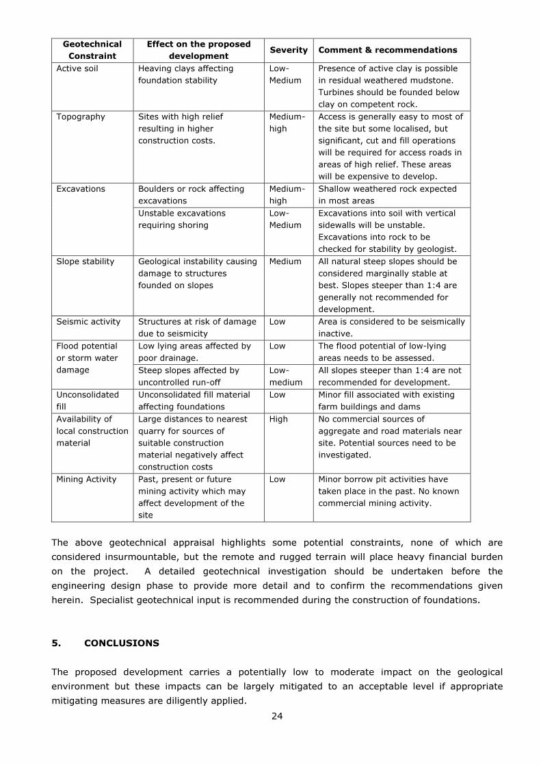
4.4. Summary of geotechnical constraints
A basic preliminary assessment of the geotechnical nature of the study area affords the
opportunity to identify any potential fatal flaws with the proposed site, such as potentially
unstable geology, and other geotechnical information which will aid the design process. A basic
assessment of the main geotechnical constraints that may impact on the civil engineering design
is given in Table 5.
Table 5: Geotechnical constraints on the proposed development
Geotechnical
Constraint
Effect on the proposed
development Severity Comment & recommendations
Collapsible &
compressible soil
Soil horizons with a
potentially collapsible or
compressible fabric
unsuitable for foundations.
Medium-
high
Transported and residual soils are
potentially compressible and
possibly collapsible. Heavy
structures & turbines should be
founded on competent rock or
engineered fill, depending on local
conditions and expected loads.
Differential
settlement (DS)
Foundations placed across
different soil types or rock
may settle differentially.
Medium Rock types and soil thickness will
vary across the site. Recommend
found individual turbines on similar
mediums.
Bearing capacity Soils with low in situ bearing
capacity resulting in high
settlements of heavy
structures if not compacted
or engineered properly
Medium Transported soils: 30-80kPa,
depending on level of
consolidation. Not suitable for
turbines.
Residual soils: 80-500kPa,
depending on type, structure and
consistency. Not suitable for
turbines.
Weathered rock: 500kPa-1mPa,
depending on lithology, structure
and state of weathering. Possibly
suitable.
Fresh, competent rock: >1mPa.
Ideal.
Saturated soils,
groundwater
problems,
perched or
permanent water
tables
Seepage from sidewalls of
excavations affecting
stability or dewatering of
trenches necessary.
Low Minor shallow perched water tables
may occur at the interface between
transported soils and residual soil
or weathered rock, but unlikely to
pose problems.
24
Geotechnical
Constraint
Effect on the proposed
development Severity Comment & recommendations
Active soil Heaving clays affecting
foundation stability
Low-
Medium
Presence of active clay is possible
in residual weathered mudstone.
Turbines should be founded below
clay on competent rock.
Topography Sites with high relief
resulting in higher
construction costs.
Medium-
high
Access is generally easy to most of
the site but some localised, but
significant, cut and fill operations
will be required for access roads in
areas of high relief. These areas
will be expensive to develop.
Excavations Boulders or rock affecting
excavations
Medium-
high
Shallow weathered rock expected
in most areas
Unstable excavations
requiring shoring
Low-
Medium
Excavations into soil with vertical
sidewalls will be unstable.
Excavations into rock to be
checked for stability by geologist.
Slope stability Geological instability causing
damage to structures
founded on slopes
Medium All natural steep slopes should be
considered marginally stable at
best. Slopes steeper than 1:4 are
generally not recommended for
development.
Seismic activity Structures at risk of damage
due to seismicity
Low Area is considered to be seismically
inactive.
Flood potential
or storm water
damage
Low lying areas affected by
poor drainage.
Low The flood potential of low-lying
areas needs to be assessed.
Steep slopes affected by
uncontrolled run-off
Low-
medium
All slopes steeper than 1:4 are not
recommended for development.
Unconsolidated
fill
Unconsolidated fill material
affecting foundations
Low Minor fill associated with existing
farm buildings and dams
Availability of
local construction
material
Large distances to nearest
quarry for sources of
suitable construction
material negatively affect
construction costs
High No commercial sources of
aggregate and road materials near
site. Potential sources need to be
investigated.
Mining Activity Past, present or future
mining activity which may
affect development of the
site
Low Minor borrow pit activities have
taken place in the past. No known
commercial mining activity.
The above geotechnical appraisal highlights some potential constraints, none of which are
considered insurmountable, but the remote and rugged terrain will place heavy financial burden
on the project. A detailed geotechnical investigation should be undertaken before the
engineering design phase to provide more detail and to confirm the recommendations given
herein. Specialist geotechnical input is recommended during the construction of foundations.
5. CONCLUSIONS
The proposed development carries a potentially low to moderate impact on the geological
environment but these impacts can be largely mitigated to an acceptable level if appropriate
mitigating measures are diligently applied.

25
The preliminary geotechnical assessment has identified some potential constraints but more
detailed geotechnical investigations should be undertaken by the developer to determine the
severity of the constraints on the proposed development.
6. REFERENCES AND BIBLIOGRAPHY
1. South African National Biodiversity website (www.sanbi.org).
2. South African Weather Service website (www.weathersa.co.za).
3. Department of Water Affairs website (www.dwaf.gov.za).
4. Department of Environmental Affairs website (www.environment.gov.za)
5. Brink, A.B.A. (1979) Engineering Geology of South Africa (Series 1-4). Building Publications,
Pretoria.
6. Identification of Problematic Soils in Southern Africa (2007). Technical notes for civil and
structural engineers. Published by the Department of Public Works.
7. Mucina, L., Rutherford, M.C. & Powrie, L.W. (eds) 2005. Vegetation map of South Africa,
Lesotho and Swaziland, 1:1 000 000 scale sheet maps. South African National Biodiversity
Institute, Pretoria.
8. Garland, G., Hoffman, T. And Todd, S. Soil degradation (in Hoffman, T., Todd, S., Ntshona, Z.
And Turner, S. (eds) (1999). Land degradation in SA, Chapter 6, NBRI, Kistenbosch.
9. 1:250 000 Geological map Sheet 3122 Victoria West (1992). Geological Survey of South
Africa. Government Printer.
10. Wienert, H. H. (1980). The Natural Road Construction Materials of Southern Africa. H&R
Academia Publ., Pretoria, 298pp.
11. SACS (1980). Stratigraphy of South Africa. Handbook 8, Geological Survey, Department of
Mineral and Energy Affairs, Government Printer, 690pp.
12. Savannah Environmental (2010) Draft Scoping Report: Proposed Karoo Renewable Energy
Facility, Northern and Western Cape Province (DEA Ref: 12/12/20/1993).