geo-referencing of video flow from small low-cost civilian uav-f4v
DESCRIPTION
IEEE TRANSACTIONS ON AUTOMATION SCIENCE AND ENGINEERINGTRANSCRIPT

156 IEEE TRANSACTIONS ON AUTOMATION SCIENCE AND ENGINEERING, VOL. 7, NO. 1, JANUARY 2010
Geo-Referencing of Video Flow From Small Low-Cost
Civilian UAV
Guoqing Zhou, Senior Member, IEEE
Abstract—This paper presents a method of geo-referencing the video
data acquired by a small low-cost UAV, which is specifically designed asan economical, moderately functional, small airborne platform intendedto meet the requirement for fast-response to time-critical events in many
small private sectors or government agencies for the small areas of interest.The developed mathematical model for geo-locating video data can simul-
taneously solve the video camera’s interior orientation parameter (IOP)(including lens distortion), and the exterior orientation parameters (EOPs)
of each video frame. With the experimental data collected by the UAV atthe established control field located in Picayune, Mississippi, the results
reveal that the boresight matrix, describing the relationship betweenattitude sensor and video camera, in a low-cost UAV system will not beable to remain a constant. This result is inconsistent with the calibrated
results from the previous airborne mapping system because the boresightmatrix was usually assumed to be a constant over an entire mission in a
traditional airborne mapping system. Thus, this paper suggests that theexterior orientation parameters of each video frame in a small low-cost
UAV should be estimated individually. With the developed method, eachvideo is geo-orthorectified and then mosaicked together to produce a2-D planimetric mapping. The accuracy of the 2-D planimetric map can
achieve 1–2 pixels, i.e., 1–2 m, when comparing with the 43 check pointsmeasured by differential GPS (DGPS) survey.
Note to Practitioners—This paper was motivated by the fact that the ex-
isting unmanned aerial vehicle (UAV) system, including hardware and soft-ware, cannot meet the requirement of real-time response to time-critical
disasters due to the barriers of UAVs mobile operation capability in re-mote site and huge time-consuming of data postprocessing and computa-tion. This paper presented an end-to-end, systematic design, and imple-
mentation of a small and low-cost UAV system, including hardware andsoftware. The entire UAV system is housed on a mobile vehicle (called field
control station) for providing command, control and data recording to andfrom the UAV platform, and real-time data processing in order to meet the
requirement of fast-response to time-critical disaster. The field control sta-tion houses the data stream monitoring and UAV position interface com-puter, radio downlinks, antenna array and video terminal. All data (GPS
data, UAV position and attitude data, and video data) are transmitted tothe ground receiver station via wireless communication, with real-time data
processing in field. The processed geo-referenced video flow, with an accu-racy of 1-2 pixels, can be immediately merged with GIS data, so that the
real-time response to disaster can be promptly deployed.
Index Terms—Geo-referencing, image processing, orthorectification, un-
manned aerial vehicle (UAV), video flow.
I. INTRODUCTION
Over the past several years, considerable effort has been put toward
the development of small, long-endurance, and low-cost unmanned
aerial vehicles (UAVs) with militarily significant payload capabilities.
Manuscript received February 19, 2008; revised July 17, 2008. First publishedMay 02, 2009; current version published January 08, 2010.This paper was rec-ommended for publication by Associate Editor K. Kyriakopoulos and Editor M.Y. Wang upon evaluation of the reviewers’ comments. This paper was supportedby U.S. National Science Foundation under Contract NSF 344521.
The author is with the Department of Civil Engineering and Technology, OldDominion University, Norfolk, VA 23529 USA, and also with the State Key Lab-oratory of Remote Sensing Science, Department of Remote Sensing and Geog-raphy, Beijing Normal University, Beijing 100875, China (e-mail: [email protected]).
Color versions of one or more of the figures in this paper are available onlineat http://ieeexplore.ieee.org.
Digital Object Identifier 10.1109/TASE.2008.2010948
For example, a small UAV initiative project was started by Program Ex-
ecutive Officer of the Secretary of the Navy for cruise missiles in 1998
([26], [24]). Afterward, the Naval Research Laboratory tested their he-
licopter UAV system ([23]), and the Naval Surface Warfare Center de-
veloped a field compatible SWARM platform which utilized a heavy
fueled engine, an on-board power supply, and an autonomous com-
mand and control system ([15]). The U.S. Army has also deployed
small UAV research and development ([27]).
The small UAVs have also generated significant interest for civil
users. NASA Ames Research Center, NASA Dryden Research Center,
and NASA Goddard Space Flight Center at Wallops Flight Facility have
developed different types of UAV systems with onboard different types
of sensors for a variety of civilian applications such as Homeland Secu-
rity demonstration (Herwitz et al. [18]), forestry fire monitoring ([9]),
quick response measurements for emergency disaster ([36]), Earth sci-
ence research (Bland et al. [6]), volcanic gas sampling ([8], [29]), hu-
manitarian biological chemo-sensing demining tasks ([4]), and mon-
itoring of gas pipelines ([17]). Especially, the civilian UAV users of
private sectors and local government agencies have a strong demand
for a low cost, moderately functional, small airborne platform, varying
in size, computerization and levels of autonomy ([30]). Therefore, ap-
plications of small UAV system for small private sector businesses
and nonmilitary government agencies for small areas of interest are
largely attracting many researchers. For example, Hruska et al. [20]
reported their small and low-cost UAVs to be primarily used for cap-
turing and down-linking real-time video. A UAV-based still imagery
work flow model including initial UAV mission planning, sensor se-
lection, UAV/sensor integration, and imagery collection, processing,
and analysis, has been developed. To enhance the analysts’ change
detection ability, a UAV-specific, GIS-based change detection system
called SADI for analyzing the differences was also development. Do-
brokhodov et al. [13] also reported a small low-cost UAV system for
autonomous target tracking, while simultaneously estimating GPS co-
ordinates of the target. A low-cost, primarily COTS system is utilized,
with a modified RC aircraft airframe, gas engine, and servos. Tracking
is enabled using a low-cost, miniature pan-tilt gimbal, driven by COTS
servos and electronics. Oh [35] and Narli and Oh [32] presented their
research result using micro-air-vehicle navigation for homeland secu-
rity, disaster mitigation, and military operations in the environment
of time-consuming, labor intensive and possibly dangerous tasks like
bomb detection, search-and-rescue, and reconnaissance. Nelson et al.
[33] reported their initial experiments in cooperative control of a team
of three small UAVs, and Barber et al. [2] presents how they deter-
mine the GPS location of a ground-based object from a fixed-wining
miniature air vehicle (MAV). Using the pixel location of the target in
an image, measurements of MAV position and attitude, and camera
pose angles, the target is localized in world coordinates. Logan et al.
[28] and Boer et al. [7] have discussed the challenges of developing
UAV system, including the difficulties encountered and proposed a list
of technology shortfalls that need to be addressed. Noth et al. [34],
within the framework of an ESA program, presented an ultra-light-
weight solar autonomous model airplane called Sky-Sailor. Johnson
et al. [22], [21] described the design, development, and operation of
UAVs developed at the Georgia Institute of Technology. Moreover, they
tested autonomous fixed-wing UAVs with the ability to hover for ap-
plications in urban or other constrained environments where the com-
bination of fast speed, endurance, and stable hovering flight can pro-
vide strategic advantages. Kang et al. [25] presented a new method of
building a probabilistic occupancy map for a UAV equipped with a laser
scanning sensor. Ryan developed a decentralized hybrid controller for
fixed-wing UAVs assisting a manned helicopter in a U.S. Coast Guard
1545-5955/$26.00 © 2009 IEEE
Authorized licensed use limited to: Imperial College London. Downloaded on June 07,2010 at 19:38:48 UTC from IEEE Xplore. Restrictions apply.

IEEE TRANSACTIONS ON AUTOMATION SCIENCE AND ENGINEERING, VOL. 7, NO. 1, JANUARY 2010 157
Fig. 1. Designed and implemented UAV platform and its components, in which the antenna labeled is a 900-MHz data transmitter.
TABLE ISPECIFICATIONS OF A LOW-COST CIVILIAN UAV PLATFORM
search and rescue mission, with which two UAVs fly on either side
of the helicopter, with constant velocity and maximum turn rate con-
straints. Sinopoli et al. [39] developed a system for autonomous naviga-
tion of UAVs based on computer vision in combination with GPS/INS.
In order to realize the fast-response to the time-critical disaster events
using UAV, one of tasks in data processing is to accurately determine
the location of ground-based objects (Barber et al. [2]). Thus, this paper
presents a method to geo-locate the ground-based object from video
stream. The closely related work has been done by a few investigators.
For example, Gibbins et al. [16] reported a geo-location system at a
location accuracy of over 20 m, and Barber et al. [2] proposed a method,
which can achieve localization errors under 5 m. Whang et al. [41] and
Dobrokhodov et al. [13] describe a geo-location solution, in which the
range estimates are obtained using a terrain model, and a nonlinear filter
is used to estimate the position and velocity of moving ground based
targets. Campbell and Wheeler [10] also presented a vision-based geo-
location system for the moving objects based on a square root sigma
point filter technology. However, the results presented in Dobrokhodov
et al. [13] and Campbell and Wheeler [10] both exhibited that the biases
in the estimate are sensitive to heavy wind conditions. Wu and Zhou
[43] developed the orthorectification for a low-cost and small UAV.
II. UAV SYSTEM
A. UAV Platform
The main contributions from us are that we employed cheap mate-
rials such as sturdy plywood, balsa wood, and fiberglass materials to
build the UAV, which features a proven versatile hi-wing design, tail
dragger landing gear with excellent ground clearance that allows oper-
ation from semi-improved surfaces. Generous flaps enable short rolling
takeoffs and slow flight. The � � ���-hp, two-stroke engine burns a
commercial glow fuel mixed with gas. The fuel is held in an external
tank just aft of the engine to avoid contamination with the payload and
optical systems, and to free up fuselage space (see Fig. 1). Especially,
the UAV is constructed to break down into a few easy to handle compo-
nents which quickly pack into a small size van, and are easily deployed,
operated and maintained by a crew of three. The specifications of the
UAV are listed in Table I, and its characteristics are as follows.
1) A relatively large payload bay for the GPS/attitude navigation de-
vice and video camera.
2) Low and slow flight capabilities maximize video quality and res-
olution.
3) Modular construction and assembly, i.e., components can be re-
moved for easy transport in a small van.
4) Mobile and rapid deployment to imaging sites.
5) An affordable, low operating cost for small private sectors, easy
to use for untrained “pilot.”
6) Meeting large-scale geospatial data accuracy needs focusing on
small areas of interest, swath, and corridor mapping for applica-
tion in quick-response to disasters.
B. Sensors and Their Integration
We employed the off-the-self sensors for the UAV platform. The
main contribution from us is that we developed an integrated sensor
board, which integrates GPS, attitude sensor (TCM2), and video
camera into a compact unit (see Fig. 2).
• Global Positioning System (GPS): A GARMIN eTrex Vista Per-
sonal Navigator Handheld GPS Receiver is selected as the UAV
positioning navigator. Its accuracy specifications are listed in
Table II. The eTrex Vista navigator has a 12 parallel channel GPS
Authorized licensed use limited to: Imperial College London. Downloaded on June 07,2010 at 19:38:48 UTC from IEEE Xplore. Restrictions apply.

158 IEEE TRANSACTIONS ON AUTOMATION SCIENCE AND ENGINEERING, VOL. 7, NO. 1, JANUARY 2010
TABLE IISPECIFICATION OF GARMIN ETREX VISTA GPS RECEIVER
Fig. 2. UAV sensor integration and payload bay for video camera and posi-tioning/attitude sensors.
TABLE IIISPECIFICATION OF ATTITUDE NAVIGATOR: TCM2-20
receiver, which continuously tracks and uses up to 12 satellites
to compute and update the position. The eTrex Vista combines a
basemap of North and South America, with a barometric altimeter
and electronic compass. The compass provides bearing informa-
tion and the altimeter determines the UAV precise altitude.
• Navigation Sensor (TCM2-20): The TCM2-20 is selected as our
attitude navigator. The specification is listed in Table III. This
sensor integrates a three-axis magneto-inductive magnetometer
and a high-performance two-axis tilt sensor (inclinometer) in a
package, and provides tilt compensated compass headings (az-
imuth, yaw, or bearing angle) and precise tilt angles relative to
Earth’s gravity (pitch and roll angle) for precise three-axis orienta-
tion. The highly accurate inclinometer allows the microprocessor
to mathematically correct for tilt. The magnetometers provide a
very large dynamic range. The electronic gimbaling eliminates
moving parts and provides information about the environment of
pitch and roll angles, and three-dimensional magnetic field mea-
surement, in addition to compass output. Data is output on a stan-
dard RS-232 serial interface with a simple text protocol that in-
cludes checksums.
• Video Camera: A Topica Color TP 6001A CCD video camera
was used to acquire the video stream at a nominal focal length
of 8.5 mm with auto and preset manual focus, and program and
manual exposure. The camera was installed in the UAV payload
bay at a nadir looking direction. The video stream is recorded
with a size of 720 (h)� 480 (v) pixel� and delivered in a MPEG-I
format.
In addition to the above three sensors, A DHR-1000NP SONY DV
Edit Recorder was used to record the data onto a tape. It comes with 12
bit or 16 bit PCM stereo audio and i.LINK DV Interface (IEEE1394)
and analog inputs/outputs. This recorder is placed the ground control
station [see Fig. 3(b)].
We especially developed an integrated sensor board (see Fig. 2) to
sense, parse and combine the TCM2 attitude sensor and the GPS data
streams into one usable data stream. It is carried in the payload bay.
The coordinated universal time (UTC) is designated to overlay onto
the real time video steam for time stamping purposes. The integrated
sensor board consists of the TCM2 sensor, two IC Basic Stamps, one
commercial video overlay board, and associated circuit components
such as resistors. The TCM2 attitude sensor has two modes of output;
continuous output of heading, roll, and pitch; and on demand output
at a baud rate of 9600. The Garmin GPS data streams are continuous
1-Hz data streams at a baud rate of 4800. Two IC Basic Stamps (mfg
Parallex) were programmed and a simple asynchronous circuit was de-
signed to provide one uniform data stream output (see Fig. 2) from each
of the Basic Stamps. One Basic Stamp parsed the GPS data streams and
the other Basic Stamp parsed the TCM2 data streams. In addition, a
spare Basic Stamp output pin was used to output the stored UTC to the
video overlay board. The integrated sensor board is a custom designed
data input/output and video overlay circuits. The data input circuit con-
tains two programmable integrated circuits, one for receipt, parsing and
storing of the GPS NEMA string and one for parsing and storing the
attitude reference data (roll, pitch, and yaw). The second IC also pro-
vides data to a video overlay board. The GPS signal is used as a “master
clock” timing signal for data and video synchronization. The GPS data
string is read, parsed, stored and overlaid onto the video at a maximum
of 2 Hz. The attitude reference board is independent of the first circuit.
The TCM2 is set at 10 Hz and provides constant roll, pitch and yaw
data to the second programmable integrated circuit registers. The data
from the TCM2 is stored at a 10 Hz rate until the first board commands
a register dump every GPS clock change. Custom code was written for
each integrated circuit to receive, parse, store, ping, and output data
from the GPS, TCM2, and RF radio modem.
C. UAV Wireless Communication
UAV command and control were realized using an off-the-self,
economical, commercial, hobby grade, nine-channel, 72-MHz system
transmitter/receiver system. The UAV pilot sends control commands
to the UAV via a handheld controller [see Fig. 3(d)]. The control
commands are received via an onboard receiver and are sent to the
appropriate control servo or throttle. The real time video is transmitted
to the ground receiver from the UAV control station via a 2.4-GHz,
S-band, transmitter with a 3-dB transmit antenna. A directional 13-dB
gain yagi receive antenna was used. During the flights a small TV
monitor was used to monitor the video quality. The video was recorded
Authorized licensed use limited to: Imperial College London. Downloaded on June 07,2010 at 19:38:48 UTC from IEEE Xplore. Restrictions apply.
IEEE TRANSACTIONS ON AUTOMATION SCIENCE AND ENGINEERING, VOL. 7, NO. 1, JANUARY 2010 159
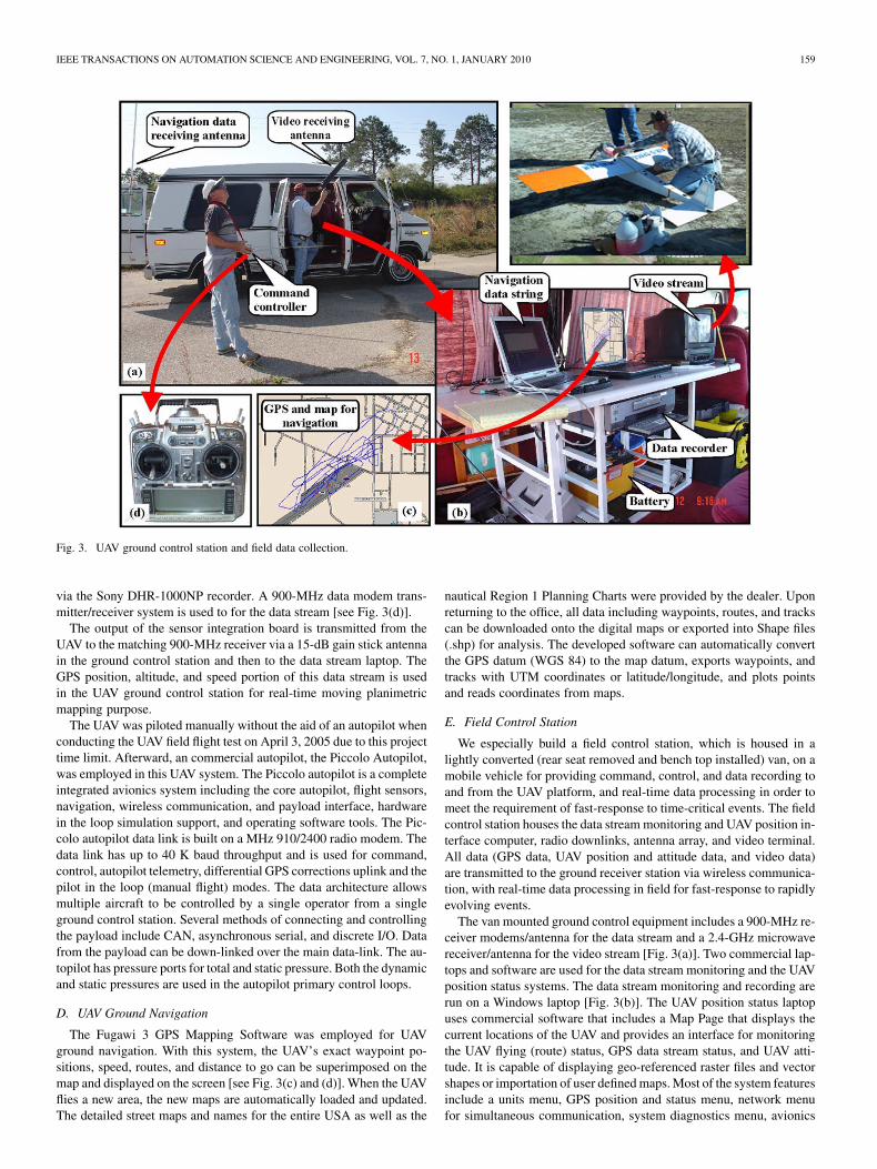
Fig. 3. UAV ground control station and field data collection.
via the Sony DHR-1000NP recorder. A 900-MHz data modem trans-
mitter/receiver system is used to for the data stream [see Fig. 3(d)].
The output of the sensor integration board is transmitted from the
UAV to the matching 900-MHz receiver via a 15-dB gain stick antenna
in the ground control station and then to the data stream laptop. The
GPS position, altitude, and speed portion of this data stream is used
in the UAV ground control station for real-time moving planimetric
mapping purpose.
The UAV was piloted manually without the aid of an autopilot when
conducting the UAV field flight test on April 3, 2005 due to this project
time limit. Afterward, an commercial autopilot, the Piccolo Autopilot,
was employed in this UAV system. The Piccolo autopilot is a complete
integrated avionics system including the core autopilot, flight sensors,
navigation, wireless communication, and payload interface, hardware
in the loop simulation support, and operating software tools. The Pic-
colo autopilot data link is built on a MHz 910/2400 radio modem. The
data link has up to 40 K baud throughput and is used for command,
control, autopilot telemetry, differential GPS corrections uplink and the
pilot in the loop (manual flight) modes. The data architecture allows
multiple aircraft to be controlled by a single operator from a single
ground control station. Several methods of connecting and controlling
the payload include CAN, asynchronous serial, and discrete I/O. Data
from the payload can be down-linked over the main data-link. The au-
topilot has pressure ports for total and static pressure. Both the dynamic
and static pressures are used in the autopilot primary control loops.
D. UAV Ground Navigation
The Fugawi 3 GPS Mapping Software was employed for UAV
ground navigation. With this system, the UAV’s exact waypoint po-
sitions, speed, routes, and distance to go can be superimposed on the
map and displayed on the screen [see Fig. 3(c) and (d)]. When the UAV
flies a new area, the new maps are automatically loaded and updated.
The detailed street maps and names for the entire USA as well as the
nautical Region 1 Planning Charts were provided by the dealer. Upon
returning to the office, all data including waypoints, routes, and tracks
can be downloaded onto the digital maps or exported into Shape files
(.shp) for analysis. The developed software can automatically convert
the GPS datum (WGS 84) to the map datum, exports waypoints, and
tracks with UTM coordinates or latitude/longitude, and plots points
and reads coordinates from maps.
E. Field Control Station
We especially build a field control station, which is housed in a
lightly converted (rear seat removed and bench top installed) van, on a
mobile vehicle for providing command, control, and data recording to
and from the UAV platform, and real-time data processing in order to
meet the requirement of fast-response to time-critical events. The field
control station houses the data stream monitoring and UAV position in-
terface computer, radio downlinks, antenna array, and video terminal.
All data (GPS data, UAV position and attitude data, and video data)
are transmitted to the ground receiver station via wireless communica-
tion, with real-time data processing in field for fast-response to rapidly
evolving events.
The van mounted ground control equipment includes a 900-MHz re-
ceiver modems/antenna for the data stream and a 2.4-GHz microwave
receiver/antenna for the video stream [Fig. 3(a)]. Two commercial lap-
tops and software are used for the data stream monitoring and the UAV
position status systems. The data stream monitoring and recording are
run on a Windows laptop [Fig. 3(b)]. The UAV position status laptop
uses commercial software that includes a Map Page that displays the
current locations of the UAV and provides an interface for monitoring
the UAV flying (route) status, GPS data stream status, and UAV atti-
tude. It is capable of displaying geo-referenced raster files and vector
shapes or importation of user defined maps. Most of the system features
include a units menu, GPS position and status menu, network menu
for simultaneous communication, system diagnostics menu, avionics
Authorized licensed use limited to: Imperial College London. Downloaded on June 07,2010 at 19:38:48 UTC from IEEE Xplore. Restrictions apply.
160 IEEE TRANSACTIONS ON AUTOMATION SCIENCE AND ENGINEERING, VOL. 7, NO. 1, JANUARY 2010
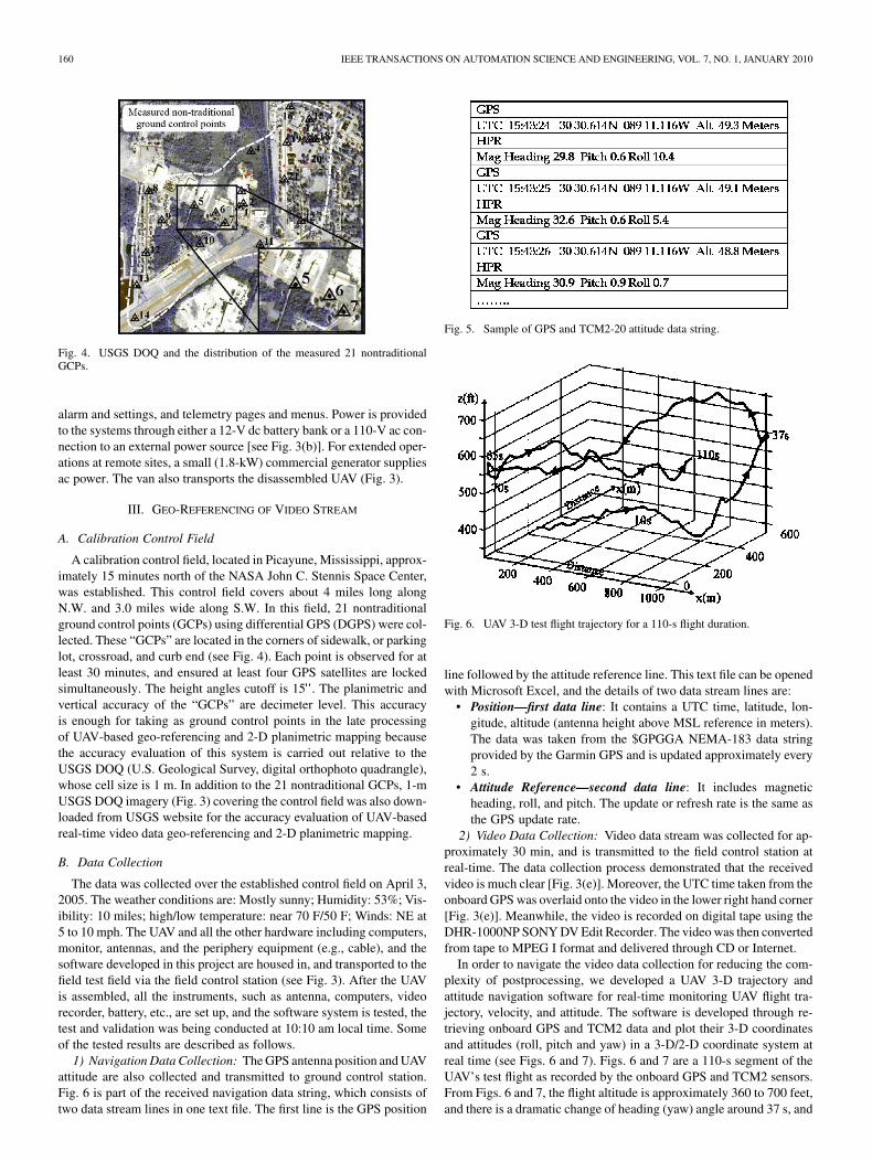
Fig. 4. USGS DOQ and the distribution of the measured 21 nontraditionalGCPs.
alarm and settings, and telemetry pages and menus. Power is provided
to the systems through either a 12-V dc battery bank or a 110-V ac con-
nection to an external power source [see Fig. 3(b)]. For extended oper-
ations at remote sites, a small (1.8-kW) commercial generator supplies
ac power. The van also transports the disassembled UAV (Fig. 3).
III. GEO-REFERENCING OF VIDEO STREAM
A. Calibration Control Field
A calibration control field, located in Picayune, Mississippi, approx-
imately 15 minutes north of the NASA John C. Stennis Space Center,
was established. This control field covers about 4 miles long along
N.W. and 3.0 miles wide along S.W. In this field, 21 nontraditional
ground control points (GCPs) using differential GPS (DGPS) were col-
lected. These “GCPs” are located in the corners of sidewalk, or parking
lot, crossroad, and curb end (see Fig. 4). Each point is observed for at
least 30 minutes, and ensured at least four GPS satellites are locked
simultaneously. The height angles cutoff is 15�. The planimetric and
vertical accuracy of the “GCPs” are decimeter level. This accuracy
is enough for taking as ground control points in the late processing
of UAV-based geo-referencing and 2-D planimetric mapping because
the accuracy evaluation of this system is carried out relative to the
USGS DOQ (U.S. Geological Survey, digital orthophoto quadrangle),
whose cell size is 1 m. In addition to the 21 nontraditional GCPs, 1-m
USGS DOQ imagery (Fig. 3) covering the control field was also down-
loaded from USGS website for the accuracy evaluation of UAV-based
real-time video data geo-referencing and 2-D planimetric mapping.
B. Data Collection
The data was collected over the established control field on April 3,
2005. The weather conditions are: Mostly sunny; Humidity: 53%; Vis-
ibility: 10 miles; high/low temperature: near 70 F/50 F; Winds: NE at
5 to 10 mph. The UAV and all the other hardware including computers,
monitor, antennas, and the periphery equipment (e.g., cable), and the
software developed in this project are housed in, and transported to the
field test field via the field control station (see Fig. 3). After the UAV
is assembled, all the instruments, such as antenna, computers, video
recorder, battery, etc., are set up, and the software system is tested, the
test and validation was being conducted at 10:10 am local time. Some
of the tested results are described as follows.
1) Navigation Data Collection: The GPS antenna position and UAV
attitude are also collected and transmitted to ground control station.
Fig. 6 is part of the received navigation data string, which consists of
two data stream lines in one text file. The first line is the GPS position
Fig. 5. Sample of GPS and TCM2-20 attitude data string.
Fig. 6. UAV 3-D test flight trajectory for a 110-s flight duration.
line followed by the attitude reference line. This text file can be opened
with Microsoft Excel, and the details of two data stream lines are:
• Position—first data line: It contains a UTC time, latitude, lon-
gitude, altitude (antenna height above MSL reference in meters).
The data was taken from the $GPGGA NEMA-183 data string
provided by the Garmin GPS and is updated approximately every
2 s.
• Attitude Reference—second data line: It includes magnetic
heading, roll, and pitch. The update or refresh rate is the same as
the GPS update rate.
2) Video Data Collection: Video data stream was collected for ap-
proximately 30 min, and is transmitted to the field control station at
real-time. The data collection process demonstrated that the received
video is much clear [Fig. 3(e)]. Moreover, the UTC time taken from the
onboard GPS was overlaid onto the video in the lower right hand corner
[Fig. 3(e)]. Meanwhile, the video is recorded on digital tape using the
DHR-1000NP SONY DV Edit Recorder. The video was then converted
from tape to MPEG I format and delivered through CD or Internet.
In order to navigate the video data collection for reducing the com-
plexity of postprocessing, we developed a UAV 3-D trajectory and
attitude navigation software for real-time monitoring UAV flight tra-
jectory, velocity, and attitude. The software is developed through re-
trieving onboard GPS and TCM2 data and plot their 3-D coordinates
and attitudes (roll, pitch and yaw) in a 3-D/2-D coordinate system at
real time (see Figs. 6 and 7). Figs. 6 and 7 are a 110-s segment of the
UAV’s test flight as recorded by the onboard GPS and TCM2 sensors.
From Figs. 6 and 7, the flight altitude is approximately 360 to 700 feet,
and there is a dramatic change of heading (yaw) angle around 37 s, and
Authorized licensed use limited to: Imperial College London. Downloaded on June 07,2010 at 19:38:48 UTC from IEEE Xplore. Restrictions apply.

IEEE TRANSACTIONS ON AUTOMATION SCIENCE AND ENGINEERING, VOL. 7, NO. 1, JANUARY 2010 161
Fig. 7. Changes of UAV attitude data: (a) roll, (b) pitch, and (c) yaw for a 110-s flight segment.
two abrupt changes in the direction of flight. In addition, it can result
that this UAV is not capable of remaining at a stable altitude, naviga-
tion direction, and velocity. As a consequence, the image resolutions
and overlaps of two neighbor video frames are probably not the same.
Using the UAV’s flight attitude and trajectory data, we can resample the
video stream for the postprocessing at a nonuniform rate depending on
the changes of these parameters.
C. Mathematical Model of Geo-Referencing of Video Stream
In order to obtain the high-accuracy of geo-referencing data, all er-
rors will have to be removed or corrected. The total error budget of
UAV-based mapping system can be derived from errors related to each
independent instrument (i.e., independent component calibration) and
from system misalignments introduced when mounting the system to
the UAV platform (i.e., the entire system calibration) ([12]). The in-
dependent component calibration of UAV system includes, such as
follows.
• The calibration for video camera—It includes interior orientation
parameters (IOPs), i.e., focal length, principal point coordinates
and lens distortion calibration. This type of error is very common,
and can be corrected via camera calibration methods.
• Navigator sensors calibration—This type of error contains the
generic GPS performance-limiting effects, including multipath,
geometric dilution of precision, integer ambiguity resolution, and
cycle slip.
Calibrations of the individual components, except in the case of
video camera calibrations, are normally made by the manufacturer;
while the system alignment calibration is usually performed by users.
The calibration includes, such as follows.
• Offset between GPS antenna and camera lens center—The re-
lationship of the GPS antenna geometric center to camera lens
center must be precisely measured.
• Kinematic GPS errors—It can be on the order of 2 ppm, which
can translate to 20 cm/100 km.
• Boresight calibration between navigation sensors and imaging
sensor (camera)—The relationship between the attitude sensor
body coordinate system and video camera coordinate system must
be precisely measured.
Authorized licensed use limited to: Imperial College London. Downloaded on June 07,2010 at 19:38:48 UTC from IEEE Xplore. Restrictions apply.
162 IEEE TRANSACTIONS ON AUTOMATION SCIENCE AND ENGINEERING, VOL. 7, NO. 1, JANUARY 2010
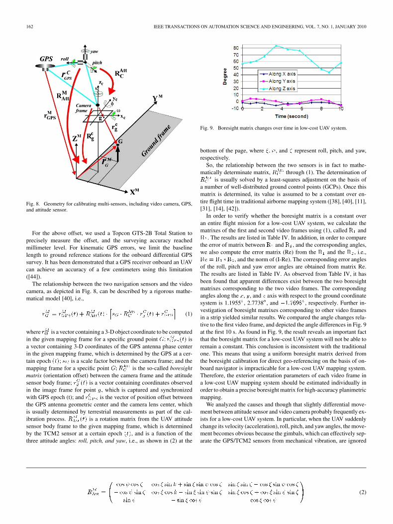
Fig. 8. Geometry for calibrating multi-sensors, including video camera, GPS,and attitude sensor.
For the above offset, we used a Topcon GTS-2B Total Station to
precisely measure the offset, and the surveying accuracy reached
millimeter level. For kinematic GPS errors, we limit the baseline
length to ground reference stations for the onboard differential GPS
survey. It has been demonstrated that a GPS receiver onboard an UAV
can achieve an accuracy of a few centimeters using this limitation
([44]).
The relationship between the two navigation sensors and the video
camera, as depicted in Fig. 8, can be described by a rigorous mathe-
matical model [40], i.e.,
��� � �
������� ��
������� � �� � �
���
� � ��� ��� � �
�(1)
where ��� is a vector containing a 3-D object coordinate to be computed
in the given mapping frame for a specific ground point �� �������� is
a vector containing 3-D coordinates of the GPS antenna phase center
in the given mapping frame, which is determined by the GPS at a cer-
tain epoch ���; �� is a scale factor between the camera frame; and the
mapping frame for a specific point ������
� is the so-called boresight
matrix (orientation offset) between the camera frame and the attitude
sensor body frame; ��� ��� is a vector containing coordinates observed
in the image frame for point �� which is captured and synchronized
with GPS epoch (t); and ����� is the vector of position offset between
the GPS antenna geometric center and the camera lens center, which
is usually determined by terrestrial measurements as part of the cal-
ibration process. �������� is a rotation matrix from the UAV attitude
sensor body frame to the given mapping frame, which is determined
by the TCM2 sensor at a certain epoch ���, and is a function of the
three attitude angles: roll, pitch, and yaw, i.e., as shown in (2) at the
Fig. 9. Boresight matrix changes over time in low-cost UAV system.
bottom of the page, where �� , and represent roll, pitch, and yaw,
respectively.
So, the relationship between the two sensors is in fact to mathe-
matically determinate matrix, ����
� through (1). The determination of
����
� is usually solved by a least-squares adjustment on the basis of
a number of well-distributed ground control points (GCPs). Once this
matrix is determined, its value is assumed to be a constant over en-
tire flight time in traditional airborne mapping system ([38], [40], [11],
[31], [14], [42]).
In order to verify whether the boresight matrix is a constant over
an entire flight mission for a low-cost UAV system, we calculate the
matrixes of the first and second video frames using (1), called �� and
��. The results are listed in Table IV. In addition, in order to compare
the error of matrix between �� and ��, and the corresponding angles,
we also compute the error matrix (Re) from the �� and the ��, i.e.,
�� � �� ���, and the norm of (I-Re). The corresponding error angles
of the roll, pitch and yaw error angles are obtained from matrix Re.
The results are listed in Table IV. As observed from Table IV, it has
been found that apparent differences exist between the two boresight
matrixes corresponding to the two video frames. The corresponding
angles along the �, �, and axis with respect to the ground coordinate
system is 1.1955�, 2.7738�, and ������, respectively. Further in-
vestigation of boresight matrixes corresponding to other video frames
in a strip yielded similar results. We compared the angle changes rela-
tive to the first video frame, and depicted the angle differences in Fig. 9
at the first 10 s. As found in Fig. 9, the result reveals an important fact
that the boresight matrix for a low-cost UAV system will not be able to
remain a constant. This conclusion is inconsistent with the traditional
one. This means that using a uniform boresight matrix derived from
the boresight calibration for direct geo-referencing on the basis of on-
board navigator is impracticable for a low-cost UAV mapping system.
Therefore, the exterior orientation parameters of each video frame in
a low-cost UAV mapping system should be estimated individually in
order to obtain a precise boresight matrix for high-accuracy planimetric
mapping.
We analyzed the causes and though that slightly differential move-
ment between attitude sensor and video camera probably frequently ex-
ists for a low-cost UAV system. In particular, when the UAV suddenly
change its velocity (acceleration), roll, pitch, and yaw angles, the move-
ment becomes obvious because the gimbals, which can effectively sep-
arate the GPS/TCM2 sensors from mechanical vibration, are ignored
����� �
�� �� �� � ���� � ��� � ��� �� ��� � ��� � �� � ��� ��
� �� ��� �� � �� � � ��� � ��� ��� ��� � �� � �� � ��� ���
��� � ��� � �� �� � ��
(2)
Authorized licensed use limited to: Imperial College London. Downloaded on June 07,2010 at 19:38:48 UTC from IEEE Xplore. Restrictions apply.

IEEE TRANSACTIONS ON AUTOMATION SCIENCE AND ENGINEERING, VOL. 7, NO. 1, JANUARY 2010 163
TABLE IVCALCULATED BORESIGHT MATRIXES FOR THE FIRST AND SECOND VIDEO FRAME (THE NORM OF (I-RE), WHERE
RE IS THE ERROR MATRIX FROM � AND � AND IS GIVEN BY �� � � � � )
TABLE VRESULTS OF THE THREE METHODS (� IS STANDARD VARIATION)
in our UAV system (Zhou et al. [44]). In other words, the camera and
attitude sensor can not be rigidly tightened to their chassis. As a result,
the boresight matrix, as determined by the above method will not re-
main a constant over the entire UAV flight mission. Thus, transforming
the navigation data derived from onboard sensors into the camera co-
ordinate system using a uniform boresight matrix seems is probably
difficult for a small low-cost UAV system (Wu and Zhou [43]).
Based on the above fact, this paper presents a method, which can
simultaneously determine ����
� , and the camera’s interior orientation
parameters, i.e., focal length ���, principal point coordinates ���� ���,and lens distortion ����. The details are as follows.
a) Determine the Camera’s IOPs: We used DLT (direct linear
transformation) method, which was originally reported by Abdel-Aziz
and Karara [1] to calibrate the video camera. This method requires a
set of ground control points whose object space and image coordinates
are already known. With 8 non-traditional GCPs that we have estab-
lished, as described in Section III-A, we calculate the camera’s IOPs
and EOPs, and listed the results in Table V. In this step, we have not
considered the lens distortion because the DLT algorithm is a low ac-
curacy calibration method, and the solved IOPs and EOPs will be em-
ployed as initial values in the later rigorous mathematical model.
b) Estimate a Coarse Boresight Matrix: With the solved the
EOPs, estimation of a coarse boresight matrix, ����
� , can be realized
through multiplication of the attitude sensor orientation data derived
from the onboard TCM2 sensor with the three angular elements of the
EOPs solved by DLT. The formula is expressed by
����
� ��� � ��
� ��� � ���������
(3)
where ����
� and ����� are the same as in (1); ��� is a rotation matrix,
which is a function of three rotation angles (��� �, and �) of a video
frame, and is expressed by (4), as shown at the bottom of the page. The
calculated results are listed in Table V.
c) Precisely Estimate the Boresight Matrix: With the coarse
values computed above, a rigorous mathematical model was es-
��
� �
����� ��� �� ����� ��� �� ����� ����� ��� �� ����� ��� �� � ����� ����� ��� ��� ����� ��� �� ����� ��� �� � ����� ����� ��� �� ����� ��� �� ����� ����� ��� ��
����� � ����� ����� ����� �����
(4)
Authorized licensed use limited to: Imperial College London. Downloaded on June 07,2010 at 19:38:48 UTC from IEEE Xplore. Restrictions apply.
164 IEEE TRANSACTIONS ON AUTOMATION SCIENCE AND ENGINEERING, VOL. 7, NO. 1, JANUARY 2010
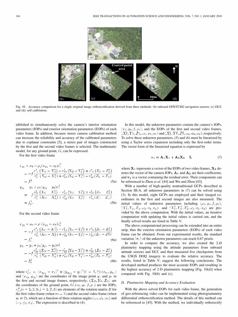
Fig. 10. Accuracy comparison for a single original image orthorectification derived from three methods: (b) onboard GPS/TCM2 navigation sensors; (c) DLT;and (d); self-calibration.
tablished to simultaneously solve the camera’s interior orientation
parameters (IOPs) and exterior orientation parameters (EOPs) of each
video frame. In addition, because stereo camera calibration method
can increase the reliability and accuracy of the calibrated parameters
due to coplanar constraints [5], a stereo pair of images constructed
by the first and the second video frames is selected. The mathematic
model, for any ground point, �, can be expressed.
For the first video frame
�� � �� � ����� � ������
� ������ �� ���
� � ���� �� � � �� � ���� �� � ��
�
���� ��� ����� � ���� ��� � � �
� � � ���� ��� � ����
� ��� (5a)
� � � � ���� � �����
� ������ �� ���
� � ���� �� � � �� � ���� �� � ��
�
���� ��� ����� � ���� ��� � � �
� � � ���� ��� � ����
� ��� (5b)
For the second video frame
�� � �� � ����� � ������
� ������ �� ���
� � ���� �� � � �� � ���� �� � ��
�
���� ��� ����� � ���� ��� � � �
� � � ���� ��� � ����
� ��� (6a)
� � � � ���� � �����
� ������ �� ���
� � ���� �� � � �� � ���� �� � ��
�
���� ��� ����� � ���� ��� � � �
� � � ���� ��� � ����
� ��� (6b)
where ����� � ��� � ���� � �� � ��
��� � �� ��� ��� � � �and ��� � � � are the coordinates of the image point � and � in
the first and second image frames, respectively; ���� ��� ��� are
the coordinates of the ground point, �� ���� �� �� ��� are the IOPs;
������ � �� �� �� � � �� �� �� are elements of the rotation matrix � for
the first video frame (when � �) and the second video frame (when
� �), which are a function of three rotation angles ���� ��� ��� and
���� ��� ���. The expression is described in (4).
In this model, the unknown parameters contain the camera’s IOPs,
���� �� �� ���, and the EOPs of the first and second video frames,
���� � �
�� � �
�� � ��� ��� ��� and ���
� � ��� � �
�� � ��� ��� ���, respectively.
To solve these unknown parameters, (5) and (6) must be linearized by
using a Taylor series expansion including only the first-order terms.
The vector form of the linearized equation is expressed by
�� � ���� ����� � � (7)
where�� represents a vector of the EOPs of two video frames,�� de-
notes the vector of the camera IOPs,�� and�� are their coefficients,
and �� is a vector containing the residual error. Their components can
be referenced to Zhou et al. [44] and Wu and Zhou [43].
With a number of high-quality nontraditional GCPs described in
Section III-A, all unknown parameters in (7) can be solved using
(3). In this model, eight GCPs are employed and their imaged co-
ordinates in the first and second images are also measured. The
initial values of unknown parameters including ���� �� �� �������
� � ��� � �
�� � ��� ��� ���� and ���
� � ��� � �
�� � ��� ��� ��� are pro-
vided by the above computation. With the initial values, an iterative
computation with updating the initial values is carried out, and the
finally solved results are listed in Table V.
The above computational processing can be extended into an entire
strip, thus the exterior orientation parameters (EOPs) of each video
frame can be obtained. From our experimental results, the standard
variation ���� of the unknown parameters can reach 0.67 pixels.
In order to compare the accuracy, we also created the 2-D
planimetry mapping using the attitude parameters from onboard
attitude sensors and DLT, and then measured five checkpoints from
the USGS DOQ imagery to evaluate the relative accuracy. The
results, listed in Table V, suggest the following conclusions: The
developed method produces the most accurate EOPs and resulting in
the highest accuracy of 2-D planimetric mapping [Fig. 10(d)] when
compared with Fig. 10(b) and (c).
D. Planimetric Mapping and Accuracy Evaluation
With the above solved EOPs for each video frame, the generation
of geo-referencing video can be implemented using photogrammetry
differential orthorectification method. The details of this method can
be referenced to [45]. With the method, we individually orthorectify
Authorized licensed use limited to: Imperial College London. Downloaded on June 07,2010 at 19:38:48 UTC from IEEE Xplore. Restrictions apply.
IEEE TRANSACTIONS ON AUTOMATION SCIENCE AND ENGINEERING, VOL. 7, NO. 1, JANUARY 2010 165
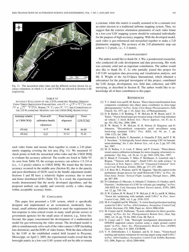
Fig. 11. The mosaicked ortho-video and the different section chosen for ac-curacy estimation, in which 11, 9, and 15 GCPs are selected in Sections I–III,respectively.
TABLE VIACCURACY EVALUATION OF THE 2-D PLANIMETRIC MAPPING DERIVED
USING THREE ORIENTATION PARAMETERS, AND �� � ���� � �� AND
�� � �� �� � ��, WHERE ����� AND �� �� � ARE COORDINATES IN
THE 2-D PLANIMETRIC MAPPING AND THE USGS DOQ, RESPECTIVELY
each video frame and mosaic them together to create a 2-D plani-
metric mapping covering the test area (Fig. 11). We measured 43
check points in both the mosaicked ortho-video and the USGS DOQ
to evaluate the accuracy achieved. The results are listed in Table VI.
As seen from Table VI, the average accuracy can achieve 1.5–2.0 m
(i.e., 1–2 pixels) relative to USGS DOQ. We found that the lowest
accuracy occurred in the middle area (Section II), due to the paucity
and poor-distribution of GCPs used in the bundle adjustment model.
Sections I and III have a relatively higher accuracy due to more
and better distributed GCPs (Table VI). In a word, the experimental
results demonstrated that the newly developed algorithms, and the
proposed method, can rapidly and correctly rectify a video image
within acceptable accuracy limits.
IV. CONCLUSION
This paper first presented a UAV system, which is specifically
designed and implemented as an economical, moderately func-
tional, small airborne platform intended to meet the requirement for
fast-response to time-critical events in many small private sectors or
government agencies for the small areas of interest, e.g., forest fire.
Second, this paper concentrated the development of a mathematical
model for geo-referencing the video stream. The developed model is
able to simultaneously solve each of the video camera’s IOP (including
lens distortion), and the EOPs of video frames. With the data collected
by the UAV at the established control field located in Picayune,
Mississippi, on April 3, 2005, the experimental results reveal that the
boresight matrix in a low-cost UAV system will not be able to remain
a constant, while this matrix is usually assumed to be a constant over
an entire mission in a traditional airborne mapping system. Thus, we
suggest that the exterior orientation parameters of each video frame
in a low-cost UAV mapping system should be estimated individually
for the purpose of high-accuracy mapping. With the developed model,
each video is geo-referenced and mosaicked together to make a 2-D
planimetric mapping. The accuracy of the 2-D planimetric map can
achieve 1–2 pixels, i.e., 1–2 meters.
ACKNOWLEDGMENT
The author would like to thank Dr. J. Wu, a postdoctoral researcher,
who conducted all code development and data processing. His work
was certainly solid and an important contribution. The author would
also like to thank Dr. C. Li who partially joined this project for
3-D UAV navigation data processing and visualization analysis, and
Mr. S. Wright of the Air-O-Space International, which obtained a
subcontract for the principal investigator of this project, contributed
the UAV design, development, test, field data collection, and GPS
surveying, as described in Section II. The author would like to ac-
knowledge all of their contribution to this paper.
REFERENCES
[1] Y. I. Abdel-Aziz and H. M. Karara, “Direct linear transformation fromcomparator coordinates into object space coordinates in close-rangephotogrammetry,” in Proc. Symp. Close-Range Photogrammetry, FallsChurch, VA, 1971, pp. 1–18, Amer. Soc. of Photogrammetry.
[2] D. B. Barber, J. D. Redding, T. W. McLain, R. W. Beard, and C. N.Taylor, “Vision-based target geo-location using a fixed-wing miniatureair vehicle,” J. Intell. Robotic Syst.: Theory Applicat., vol. 47, no. 4,pp. 361–382, Dec. 2006, 2006.
[3] R. W. Beard, T. W. McLain, D. B. Nelson, D. Kingston, and D.Johanson, “Decentralized cooperative aerial surveillance usingfixed-wing miniature UAVs,” Proc. IEEE, vol. 94, no. 7, pp.1306–1323, Jul. 2006.
[4] Bermudez, S. Badia, U. Bernardet, A. Guanella, P. Pyk, and P. F. M.J. Verschure, “A biologically based chemo-sensing UAV for humani-tarian demining,” Int. J. Adv. Robotic Syst., vol. 4, no. 2, pp. 187–198,Jun. 2007.
[5] M. D. Bethea, J. A. Lock, F. Merat, and P. Crouser, “Three-dimen-sional camera calibration technique for stereo imaging velocimetry ex-periments,” Opt. Eng., vol. 36, no. 12, pp. 3445–3454, Dec. 1997.
[6] G. Bland, P. Coronado, T. Miles, P. Bretthauer, A. Lunsford, and J.Bognar, ““Sensors with wings”—Small UAVs for earth science,” inCollection of Tech. Papers—AIAA 3rd “Unmanned-Unlimited” Tech-
nical Conf. Workshop, Exhibit, 2004, pp. 317–327, 2004.[7] J.-F. Boer, M. L. Preatoni, and G. M. Saggiani, “Specific aspects in the
preliminary design process for small Rotorcraft UAVs,” in Proc. Int.
62nd Annu. Forum—Vertical Flight: Leading Through Innov., 2006,pp. 887–898.
[8] D. Caltabiano, G. Muscato, A. Orlando, C. Federico, G. Giudice, and S.Guerrieri, “Architecture of a UAV for volcanic gas sampling,” in Proc.
10th IEEE Int. Conf. Emerging Technol. Factory Autom., ETFA, 2005,vol. 12, pp. 739–744.
[9] D. W. Casbeer, R. W. Beard, T. W. McLain, S.-M. Li, and R. K. Mehra,“Forest fire monitoring with multiple small UAVs,” in Proc. Amer.
Control Conf., 2005, vol. 5, pp. 3530–3535.[10] M. E. Campbell and M. Wheeler, “A vision based geolocation tracking
system for UAVs,” in Proc. AIAA Guidance, Navigation, Control Conf.
Exhibit, Keystone, CO, 2006, Paper no. AIAA-2006-6246.[11] M. Cramer and D. Stallmann, “System calibration for direct georefer-
encing,” in Proc. Int. Soc. Photogrammetry Remote Sens., Graz, Sep.2002, vol. 34, pp. 79–84, 2002, Com. III, Part A.
[12] N. Csanyi and C. Toth, “Boresight misalignment determination ofGPS/INS supported camera systems using a single ground controlpoint,” in Proc. Amer. Soc. Photogrammetry Remote Sens. (ASPRS)
Annu. Conf., May 5–9, 2003, CD-ROM.[13] V. N. Dobrokhodov, I. I. Kaminer, and K. D. Jones, “Vision-based
tracking and motion estimation for moving targets using small UAVs,”in Proc. AIAA Guidance, Navigation, Control Conf. Exhibit, Keystone,CO, 2006, Paper no. AIAA-2006-6606.
Authorized licensed use limited to: Imperial College London. Downloaded on June 07,2010 at 19:38:48 UTC from IEEE Xplore. Restrictions apply.
166 IEEE TRANSACTIONS ON AUTOMATION SCIENCE AND ENGINEERING, VOL. 7, NO. 1, JANUARY 2010
[14] A. G. Grejner-Brzezinska, “Direct exterior orientation of airborne im-
agery with GPS/INS system-performance analysis,” J. Inst. Naviga-
tion, vol. 46, no. 4, pp. 261–270, 1999, 1999.
[15] D. Furey, “SWARM UAV—Development of a small, very low cost,
high endurance UAV,” in Proc. AUVSI’s Unmanned Syst. North Amer.,
2004, pp. 1339–1349.
[16] D. Gibbins, P. Roberts, and L. Swierkowski, “A video geo-location
and image enhancement tool for small unmanned air vehicles (UAVs),”
in Proc. Intelligent Sens., Sens. Netw. Inf. Process. Conf., Melborne,
Australia, 2004, pp. 469–473.
[17] D. Hausamann, W. Zirnig, G. Schreier, and P. Strobl, “Monitoring
of gas pipelines—A civil UAV application,” Aircraft Eng. Aerosp.
Technol., vol. 77, no. 5, pp. 352–360, 2005, 2005.
[18] S. R. Herwitz, R. Berthold, S. Dunagan, D. Sullivan, M. Fladeland, and
J. A. Brass, “UAV homeland security demonstration,” in Proc. AIAA
3rd “Unmanned-Unlimited” Tech. Conf. Workshop, Exhibit, 2004, pp.
396–400, 2004.
[19] L. Holly and R. Colgren, “Small UAV and RPV inertial flight test in-
strumentation systems,” in Proc. 35th Annu. Symp. Flight Test—The
Next Hundred Years, 2004, pp. 269–283.
[20] R. C. Hruska, G. D. Lancaster, J. L. Harbour, and S. J. Cherry, “Small
UAV-acquired, high-resolution, georeferenced still imagery,” in Proc.,
AUVSI’s Unmanned Syst. North Amer., 2005, pp. 837–840.
[21] E. N. Johnson, D. P. Schrage, J. V. R. Prasad, and G. J. Vachtsevanos,
“UAV flight test programs at Georgia Tech,” in Proc. AIAA 3rd
“Unmanned-Unlimited” Technical Conf. Workshop, Exhibit, 2004,
pp. 527–539, 2004.
[22] E. N. Johnson, M. A. Turbe, A. D. Wu, S. K. Kannan, and J.
C. Neidhoefer, “Flight test results of autonomous fixed-wing UAV
transitions to and from stationary hover,” in Proc. AIAA Guidance,
Navigation, Control Conf., Keystone, CO, Aug. 21–24, 2006, pp.
5144–5167, 2006.
[23] A. D. Kahn and R. J. Foch, “Attitude command attitude hold and
stability augmentation systems for a small-scale helicopter UAV,”
in Proc. AIAA/IEEE Digital Avionics Syst. Conf., 2003, vol. 2, pp.
8.A.4/1–8.A.4/10.
[24] I. I. Kaminer, O. A. Yakimenko, V. N. Dobrokhodov, M. I. Lizarraga,
and A. M. Pascoal, “Cooperative control of small UAVs for naval ap-
plications,” in Proc. IEEE Conf. Decision Control, 2004, vol. 1, pp.
626–631.
[25] Y. Kang, D. S. Caveney, and J. K. Hedrick, “Probabilistic mapping
for UAV using point-mass target detection,” in Proc. AIAA Guidance,
Navigation, Control Conf., Keystone, CO, Aug. 21–24, 2006, pp.
1915–1926, 2006.
[26] K. K. Kelley, “Small UAV initiative,” Proc. SPIE, vol. 4127, pp. 46–48,
2000.
[27] J. Kucera, “Army to deploy new small UAV,” Jane’s Defence Weekly,
Apr. 2005, 2005, 1p.
[28] M. J. Logan, T. L. Vranas, M. Motter, Q. Shams, and D. S. Pollock,
“Technology challenges in small UAV development,” Collection
of Tech. Papers—InfoTech at Aerospace: Advancing Contemporary
Aerospace Technol. Their Integration, vol. 3, pp. 1644–1648, 2005,
2005.
[29] A. A. Longo, P. Pace, and S. Marano, “A system for monitoring vol-
canoes activities using high altitude platform stations,” 55th Int. Astro-
naut. Congr., vol. 2, pp. 1203–1210, 2004.
[30] M. Moore, C. Rizos, and J. Wang, “Issues concerning the implemen-
tation of a low cost attitude solution for an unmanned airborne ve-
hicle (UAV),” in Proc. 6th Int. Symp. Satellite Navigation Technol. In-
cluding Mobile Positioning Location Services, Melbourne, Australia,
Jul. 22–25, 2003, CD-ROM.
[31] M. R. Mostafa, K. P. Schwarz, and M. A. Chapman, “Development and
testing of an airborne remote sensing multi-sensor system,” in Proc.
ISPRS Commission II, Symp. Data Integration: Syst. Tech., Cambridge,
U.K., Jul. 1998.
[32] V. Narli and P. Y. Oh, “Near-earth unmanned aerial vehicles: Sensor
suite testing and evaluation,” in Proc. ASME Int. Design Eng. Tech.
Conf. Comput. Inf. Eng. Conf., 2006, DETC2006, 2006, 7p.
[33] D. R. Nelson, T. W. McLain, R. S. Christiansen, R. W. Beard,
and D. Johansen, “Initial experiments in cooperative control of
unmanned air vehicles,” in Collection of Technical Papers—AIAA
3rd “Unmanned-Unlimited” Tech. Conf. Workshop, Exhibit, 2004,
pp. 666–674, 2004.
[34] A. Noth, W. Engel, and R. Siegwart, “Design of an ultra-lightweight
autonomous solar airplane for continuous flight,” in Proc. Int. Conf.
Field Service Robotics, Port Douglas, Australia, Jul. 29–31, 2005.
[35] P. Y. Oh, “Flying insect inspired vision for micro-air-vehicle navi-
gation,” in Proc. AUVSI’s Unmanned Syst. North Amer., 2004, pp.
2201–2208, 2004.
[36] G. W. Postell and T. J. Pittman, “Wallops flight facility uninhabited
aerial vehicle (UAV) user’s handbook,” Suborbital and Special Orbital
Projects Directorate, 840-HDBK-0002, NASA Wallops Flight Facility,
Documentation Web Site, Apr. 15, 2005 [Online]. Available: http://
www.wff.aasa.gov
[37] A. D. Ryan, D. L. Nguyen, and J. K. Hedrick, “Hybrid control
for UAV-assisted search and rescue,” in Proc. ASME Dynamic Syst.
Control Division, Orlando, FL, Nov. 5–11, 2005, pp. 187–195,
2005.
[38] K. P. Schwarz, M. E. Chapman, E. Cannon, and P. Gong, “An inte-
grated INS/GPS approach to the georeferencing of remotely sensed
data,” Photogrammetric Eng. Remote Sens., vol. 59, pp. 1667–1674,
1993.
[39] B. Sinopoli, M. Micheli, G. Donato, and T. J. Koo, “Vision based
navigation for an unmanned aerial vehicle,” in Proc. IEEE Int.
Conf. Robotics Autom. (ICRA), Seoul, Korea, May 21–26, 2001, pp.
1757–1764, 2001.
[40] J. Skaloud, M. Cramer, and K. P. Schwarz, “Exterior orientation by
direct measurement of camera and position,” in Proc. Int. Archives
Photogrammetry Remote Sens., Vienna, Austria, 1996, vol. XXXI, pp.
125–130, Part B3.
[41] I. H. Whang, V. N. Dobrokhodov, I. I. Kaminer, and K. D. Jones,
“On vision-based tracking and range estimation for small UAVs,” in
Proc. AIAA Guidance, Navigation, Control Conf. Exhibit, San Fran-
cisco, CA, 2005, Paper no. AIAA-2005-6401.
[42] N. Yastikli and K. Jacobsen, “Influence of system calibration on direct
sensor orientation,” Photogrammetric Eng. Remote Sens., vol. 71, no.
5, p. 629, May 2005.
[43] J. Wu and G. Zhou, “Low-cost unmanned aerial vehicle (UAV) video
orthorectification,” in Proc. IEEE Int. Geosi. Remote Sens. Symp.,
Denver, CO, Jul. 31, 2006–Aug. 4, 2006 .
[44] G. Zhou, J. Wu, S. Wright, and J. Gao, “High-resolution UAV video
data processing for forest fire surveillance,” Old Dominion Univ., Nor-
folk, VA, Tech. Rep. National Sci. Foundation, Aug. 2006, 82p.
[45] G. Zhou, K. Jezek, and W. Wright, “Orthorectifying 1960’s desclas-
sified intelligence satellite photography (DISP) of Greenland,” IEEE
Trans. Geosci. Remote Sens., vol. 40, no. 6, pp. 1247–1259, Jun.
2002.
Authorized licensed use limited to: Imperial College London. Downloaded on June 07,2010 at 19:38:48 UTC from IEEE Xplore. Restrictions apply.