g:engineeringdrawingsreleasedproduct information sheetsfor ... · o maxmin25 (max, min, and 25°c)...
TRANSCRIPT

I n fo r m a t i o n su b je c t t o ch a n g e w i t h o u t n o t i c e .
© Q u a l i t ro l i s a n IS O 9 0 0 1 s y s t em c e r t i f i e d co m p a n y .
Control #______________________ Issue Date _______Replaces ________________________ Sheet ___ Of ___
Product Information
+25°C
Q U A L I T R O L C O R P . F A I R P O R T NY U . S . A MIN
MAX
GD
AL
-02
6-6
29
LEVELLIQUID
6" Gear Drive Liquid Level GaugeGeneral
PI-LLG042 Rev-30805Rev-28821
11-14-121 5
I n fo r m a t i o n su b je c t t o ch a n g e w i t h o u t n o t i c e .
© Q u a l i t ro l i s a n IS O 9 0 0 1 s y s t em c e r t i f i e d co m p a n y .
Control #______________________ Issue Date _______Replaces ________________________ Sheet ___ Of ___
Product Information
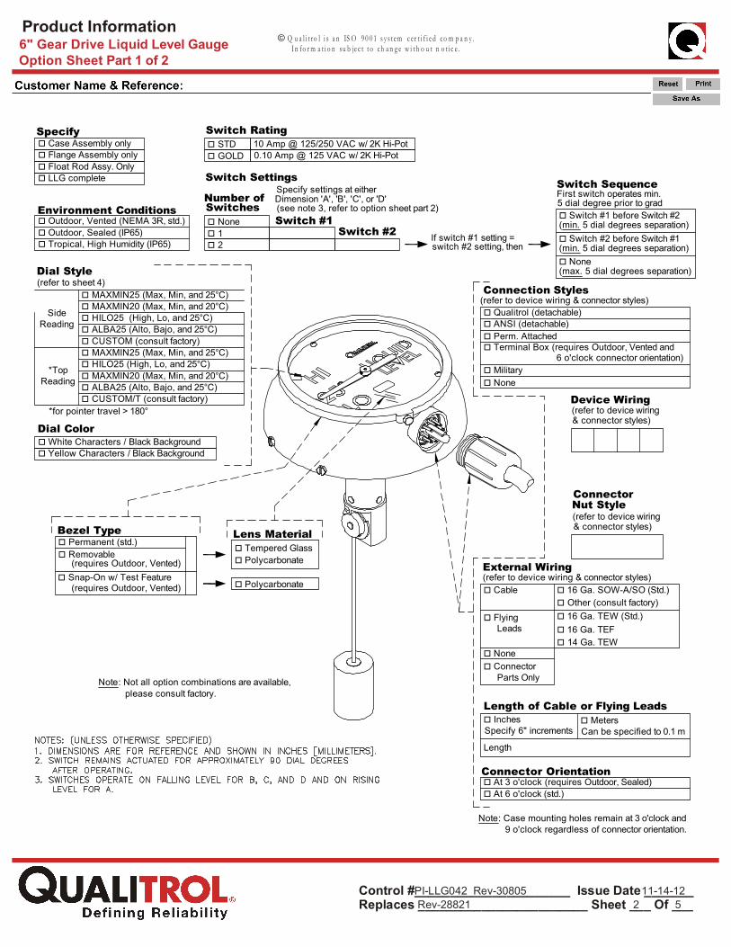
Specifyo Case Assembly onlyo Flange Assembly onlyo Float Rod Assy. Only
Switch Rating10 Amp @ 125/250 VAC w/ 2K Hi-Poto STD
o GOLD
Environment Conditionso Outdoor, Vented (NEMA 3R, std.)o Outdoor, Sealed (IP65)
Switch Settings
o Noneo 1o 2
o Qualitrol (detachable)o ANSI (detachable)o Perm. Attachedo Terminal Box (requires Outdoor, Vented and
(refer to device wiring & connector styles)
Device Wiring
o Cable
o Flying Leads
o Noneo Connector Parts Only
(refer to device wiring & connector styles)o 16 Ga. SOW-A/SO (Std.)o Other (consult factory)o 16 Ga. TEW (Std.)o 16 Ga. TEFo 14 Ga. TEW
o InchesLength of Cable or Flying Leads
o MetersSpecify 6" increments Can be specified to 0.1 m
Length
Connector
o Tropical, High Humidity (IP65)
Bezel Typeo Permanent (std.)o Removable
o Snap-On w/ Test Feature
Dimension 'A', 'B', 'C', or 'D'Switches
Switch #1Switch #2
Number of
Lens Materialo Tempered Glasso Polycarbonate
Specify settings at either
o Switch #1 before Switch #2
o Switch #2 before Switch #1
Switch SequenceFirst switch operates min.
0.10 Amp @ 125 VAC w/ 2K Hi-Pot
Dial Coloro White Characters / Black Backgroundo Yellow Characters / Black Background
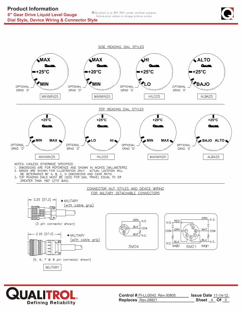
Dial Style
o MAXMIN25 (Max, Min, and 25°C)o MAXMIN20 (Max, Min, and 20°C)o HILO25 (High, Lo, and 25°C)
o ALBA25 (Alto, Bajo, and 25°C)
o CUSTOM (consult factory)o MAXMIN25 (Max, Min, and 25°C)
SideReading
*TopReading
o CUSTOM/T (consult factory)
o ALBA25 (Alto, Bajo, and 25°C)
Connector Orientationo At 3 o'clock (requires Outdoor, Sealed)o At 6 o'clock (std.)
(refer to device wiring& connector styles)
Nut Style(refer to device wiring& connector styles)
Connection Styles
External Wiring
(refer to sheet 4)
(see note 3, refer to option sheet part 2)
o None
o Polycarbonate
switch #2 setting, thenIf switch #1 setting =
(min. 5 dial degrees separation)
(min. 5 dial degrees separation)
5 dial degree prior to grad
(requires Outdoor, Vented)
(requires Outdoor, Vented)
Note: Case mounting holes remain at 3 o'clock and 9 o'clock regardless of connector orientation.
o None(max. 5 dial degrees separation)
o Military
Note: Not all option combinations are available, please consult factory.
6 o'clock connector orientation)
*for pointer travel > 180°
o LLG complete
6" Gear Drive Liquid Level GaugeOption Sheet Part 1 of 2
PI-LLG042 Rev-30805Rev-28821
11-14-122 5
o HILO25 (High, Lo, and 25°C)o MAXMIN20 (Max, Min, and 20°C)

I n fo r m a t i o n su b je c t t o ch a n g e w i t h o u t n o t i c e .
© Q u a l i t ro l i s a n IS O 9 0 0 1 s y s t em c e r t i f i e d co m p a n y .
Control #______________________ Issue Date _______Replaces ________________________ Sheet ___ Of ___
Product Information
Lengtho 2.17 / 55MMo 2.50 / 63MMo 2.76 / 70MMo 3.15 / 80MMo 3.58 / 91MMo 3.94 / 100MMo 4.25 / 108MMo 4.92 / 125MMo 5.25 / 133MMo 5.91 / 150MM
o 7.87 / 200MMo 10.4 / 265MM
Gear Drive Flange Mounting Styles45° 3.125 Ø.28 2.75 O.D. x 2.13 I.D. x .13 x .06 DP.45° 3.125 Ø.34 2.75 O.D. x 2.13 I.D. x .06 DP.
#10-32#10-32
45°45°45°45°45°45°45°45°90°90°
3.1253.1254.0004.0004.0004.0004.7505.000
90°90°90°45°
3.1253.1253.1253.1253.1254.000
Ø.34Ø.34Ø.44Ø.44Ø.44Ø.44Ø.56Ø.34Ø.34
Ø.34Ø.34
Ø.28Ø.28
Ø13MM
2.75 O.D. x 2.13 I.D. x .13 x .06 DP. #10-322.63 O.D. x 1.75 I.D. x .08 DP. #10-323.38 O.D. x 2.63 I.D. x .06 DP.N/A3.38 O.D. x 2.63 I.D. x .13 x .09 DP.3.38 O.D. x 2.63 I.D. x .09 DP.4.00 O.D. x 3.12 I.D. x .12 DP.3.81 O.D. x 3.31 I.D. x .13 DP.2.75 O.D. x 2.13 I.D. x .06 DP.2.75 O.D. x 2.13 I.D. x .06 DP.N/A2.75 O.D. x 2.13 I.D. x .13 x .06 DP.2.63 O.D. x 1.75 I.D. x .08 DP.N/A
#10-32#10-32#10-32#10-32#10-32#10-32#10-32#10-32#10-32#10-32#10-32
M5
45E3145E32
45E3445E4145E4245E4345E4445E4545E5190E31
45E33
90E3290E3390E3490E3545M41
oo
ooo
oooo
oooo
ooo
STDo HEAVY DUTYoSTDo
STDo oSTDoSTDo
STDoSTDo oSTDoSTDo
STDo oSTDoSTDo oSTDo
STDoSTDoSTDo o
STD Only
STD orHEAVY DUTY
HEAVY DUTYOnly
Application/Float Rod Styleo Roller (for Bladder bags, U.S. Style)o Straight (for Straight Float Rods)o G-Roller (for Bladder Bags, Euro Style)
Flange Construction
Data TypeAngles
Oil Levels
o
o
o InchesRadius
o Millimetersspecified to .10" increments
Length =
Gear Ratioo 2:1 Recommended for float travel > 45 degreeso 3:1 Non-Standardo 4:1 Recommended for float travel 45 degrees
Mounting Angle
o -15 degreeso -30 degreeso -45 degrees
o 0 (Horizontal)
Max Angle/Level
Min Angle/Level
20°C/25°C Angle/Level
Optional Grad Angle/Level*B =
Data Input
*A = (required except when orderingflange assembly only)
(optional 4th graduation mark)
(required)
(required) *D =
*C =
*use minus sign (-) for angles or oil levels below horizontal c/land plus sign (+) for angles or oil levels above horizontal c/l
D must be between C & B
Given from
Given from
Horizontal Center Line
Horizontal Center Line(Same Units as Radius)
in 1 mm increments
(in inches unless otherwise noted)
Support Tube FlangeConstruction(inches/mm)
min/max lengthin inches [mm]
///
HOLEORIENTATION
B.C. HOLE GASKET GROOVE CASE MOUNTINGFLANGEOPTION
HEAVY DUTY
HEAVY DUTY
HEAVY DUTY
HEAVY DUTY
HEAVY DUTY
27.0 [686] 105.0 [2667]6.0 [152] 42.0 [1067]
11.8 [300] 98.4 [2500]
Can be Specify
Note : If radius is specified in mm, then ROLLER/G-ROLLER float rod hardware will be metric.
45° 4.000 Ø7MM 87MM O.D. x 72.4MM I.D. x 4.3MM DP.45M42o M5 STDo o HEAVY DUTY
o 6.38 / 162MM
Note: Not all option combinations are available, please consult factory.
o Other
minimum A,B,C,Dangular separation
6 °4 °3 °
Notes: (A-B) x (Gear Ratio) must be between 45° and 270° inclusive. Maintain minimum A,B,C,D angular separation per Gear Ratio table.
o 11.5 / 292MM
o HEAVY DUTY
6" Gear Drive Liquid Level GaugeOption Sheet Part 2 of 2
PI-LLG042 Rev-30805Rev-28821
11-14-123 5
I n fo r m a t i o n su b je c t t o ch a n g e w i t h o u t n o t i c e .
© Q u a l i t ro l i s a n IS O 9 0 0 1 s y s t em c e r t i f i e d co m p a n y .
Control #______________________ Issue Date _______Replaces ________________________ Sheet ___ Of ___
Product Information6" Gear Drive Liquid Level GaugeDial Style, Device Wiring & Connector Style
PI-LLG042 Rev-30805Rev-28821
11-14-124 5
+25°C
Q UA L I T RO L CO R P . F A I R P O R T N Y U . S . A MIN
MAXD
6W
-M
AX
MI
N2
5
Q UA L I T R O L C O R P . F A I R P O R T N Y U . S . A MIN
MAX
D6
W-
MA
XM
IN
20
Q UA L I T RO L CO R P . F A I R P OR T NY U . S . A LO
HI
D6
W-
HI
LO
25
Q UA L I T R O L C O R P . F A I R P O R T N Y U . S . A BAJO
ALTO
D6
W-
AL
BA
25
QUA L
I T R O L C O R P . F A I R P O R T NY U . S . A
LO HI
D 6 W - M A X MI N
2
5/
T
+20°C +25°C
+25°C
QU A LI T RO L C O R P . F A I R P O R T N Y U . S . A
MIN MAX
D 6 W- A
LB
A2
5
/T
+20°C
+25°C
QU A
L I T R O L CO R P . F A I RP O RT NY U . S . A
BAJO ALTO
D 6 W- A
LB
A2
5
/T
+25°C
QU AL I T R O L C O R P . F A I R P O R T NY U . S . A
MIN MAX
D 6 W - M A X MI N
2
5/
T
+25°C

I n fo r m a t i o n su b je c t t o ch a n g e w i t h o u t n o t i c e .
© Q u a l i t ro l i s a n IS O 9 0 0 1 s y s t em c e r t i f i e d co m p a n y .
Control #______________________ Issue Date _______Replaces ________________________ Sheet ___ Of ___
Product Information6" Gear Drive Liquid Level GaugeDevice Wiring & Connector Styles
PI-LLG042 Rev-30805Rev-28821
11-14-125 5
SPIN NUT (CONDUIT ADAPTOR)
SPIN NUT (FLEX CONDUIT ADAPTOR)
CONDUIT ADAPTOR
STANDARD NUT
TERMINAL BOX: 1 & 2 SWITCH W/ GROUND(2 SWITCH VERSION SHOWN)
TERMINAL BOX: 1 & 2 SWITCH W/ GROUND(2 SWITCH VERSION SHOWN)