generic spine model with simple physics for life-like
TRANSCRIPT

Workshop on Virtual Reality Interaction and Physical Simulation VRIPHYS (2012)J. Bender, A. Kuijper, D. W. Fellner, and É. Guérin (Editors)
Generic Spine Model with Simple Physics for Life-LikeQuadrupeds and Reptiles
Ahmad Abdul Karim1,2, Alexandre Meyer1, Thibaut Gaudin2, Axel Buendia2,3 and Saida Bouakaz1
1 Université de Lyon, CNRS1 Université Lyon 1, LIRIS, UMR5205, F-69622, France
2 Spir.Ops Artificial Intelligence, Paris, France3 CNAM − CEDRIC, 292, rue St Martin, 75003 Paris, France
(4 (5 (3 (2 (1
Figure 1: Example of our system generated animation: from right to left, a wolf animated using the pseudo-physics and flexiblespine model.
AbstractWe propose a pseudo-physics system and a spine model that can be coupled to generate life-like locomotionanimations of quadrupeds and reptiles. The pseudo-physics system uses minimalist particle-based physics andvalues of the gait pattern to generate the sinusoidal-like ballistic movement of the pelvis observed in nature. Whilethe spine model uses simple geometry-based calculations and 3D Hermite curves to generate a flexible spinemodel, giving the animated creatures more agility. Our final system is totally controllable by the user in order togenerate any desired style.
Categories and Subject Descriptors (according to ACM CCS): I.3.7 [Computer Graphics]: Three-DimensionalGraphics and Realism—Animation
1. Introduction
Animated creatures in virtual worlds like arachnids,quadrupeds, reptiles etc. should have the ability to movefreely in a convincing and a life-like way, in order to makethe virtual experience more immersive. The movement ofthese creatures is governed essentially by their morphology,as their complex anatomies impose constraints on theirway of displacement. They move in different locomotionstyles based on different sets of gait patterns. Simulatingthe actual physics and anatomy constraints of these multi-legged characters is quite complex. But in most computer-based applications like games or multimedia virtual worlds,the most important thing is the plausibility of the generatedmotion [BHW96] more than the accuracy of the calculations.
Even with simplified calculations, produced animationscan be realistic and believable in comparison to motionsgenerated using complex physics-based calculations. Plus,they offer a better control over the final animation.
Contribution. We propose a simple pseudo-physicssystem and a generic spine model that help to animatevirtual creatures in a life-like way (Figure 1). The goal ofthe pseudo-physics system is to generate the sinusoidal-likeballistic movement of the pelvis observed in nature. To doso, we simplify calculations by using particle-based physicsequations. Based on the gait pattern and Newton second lawsof physics we calculate the force that each foot is exerting onthe pelvis on each simulation step. We also add a flexiblespine model when simulating quadrupeds and reptiles to
c© The Eurographics Association 2012.

A. Abdul Karim, A. Meyer, T. Gaudin, A. Buendia & S. Bouakaz / Pseudo-Physics & Spine Model
give them the agility observed in real-life animals. Ourspine model is quite generic and can be applied on differentmorphologies. It uses simple geometry-based calculationsand 3D Hermite curves. By coupling the spine model withthe pseudo-physics system the final locomotion becomesbelievable and more realistic. These added components aretotally controllable giving the user the ability to generate anyneeded locomotion style.
2. Related Work
There are many techniques for generating locomotion, manyof them target human-like morphologies (bipeds). Multonet al. in [MFCD99] and more recently van Welbergen etal. in [vWvBE∗10] identified two main groups: Data-Driventechniques and Procedural-Based techniques with twosubcategories physics-based and kinematic-based. Skrba etal. in [SRH∗08, SRH∗09] show in their survey that sametechniques are used for quadrupeds animation: Data-Driven,physics-based models, IK systems or some combination ofthe above.
A wide variety of input data are used to generate multi-legged characters animation. For instance, early work ofMcKenna et al. in [MZ90] uses gait patterns observedin biology and oscillatory-based dynamics to animate acockroach model that adapts to planar and uneven terrain.More recently, Favreau et al. in [FRDC04] extract 3Dcyclic motion of animals from video sequences using imageprocessing techniques. Kry et al. in [KRFC09] animate adog model by making a subset of its joints vibrates withspecific periods and with low frequencies, which inducespassive movement in other connected joints and rigid bodies.In [CKJ∗11], Coros et al. use gait patterns and dynamicvalues (forces/torques) extracted from MoCap, to animatea dog capable of a wide range of locomotion on a straightline. These systems are, most of the time, morphologyspecific meaning that they can animate only a specificmorphology like a dog in [CKJ∗11], a horse in [TCHL12] ora quadruped robot (Called BigDog by Boston Dynamics TM)in [RBNP08].
We are more interested in morphology independentsystems like the PODA system proposed by Girard etal. in [GM85, Gir87] as they can animate a multitude ofmorphologies with nearly no constraints. PODA is one ofthe earliest procedural-centric locomotion controllers. Theyuse it to animate a wide range of multi-legged characterson planar terrain (bipeds, quadrupeds, etc. ). The user onlyneeds to specify the gait pattern (an example of a gaitpattern is shown in Figure 4), everything else is calculatedautomatically. They add pseudo-physics calculations to thepelvis of the multi-legged character, making it reacts to thefeet movement in the horizontal and sagittal plane in a morebelievable way. But in their system the user needs to fix andtweak by hand the force of each foot in order to achieve theneeded effect, while in our system (Section 4) we aim for a
transparent control for the user with no need for any extrasettings.
Another interesting system is the one used in the gameSpore TM (by Maxis Studio TM ). Where Hecker et al. in[HRE∗08] created a system capable of animating multi-legged characters whose morphologies are unknown whencreating the actual animation system. These characters canbe created by the user in run-time. Their animation databasecontains semantically generalized keyframe data specializedin real-time based on the actual new morphology.
Finally, most of the systems discuss the importance ofadding a spine-like model while animating multi-leggedcharacters (specially quadrupeds) in order to generate morenatural results [CKJ∗11, CR06]. An important issue that weaddress in more details in Section 5.
3. Locomotion Controller
Pelvis
Gait
Manager
User
Figure 2: Locomotion controller overview.
Locomotion is the act of moving from one place toanother. For most terrestrial animals that means putting onefoot in front of the others in a successive way until reachingthe designated point of interest (target). During a normalfoot movement there are two main phases Stance and Swingphase [INM66]. During the stance phase a foot is blockedon the ground. While in swing phase (flight phase) the footflies in a parabolic-like curve toward its target without anyground contact.
Our system follows these principles when generatinglocomotion. It is kinematic-based and inspired by thelocomotion controllers found in [GM85, Gir87, AGM∗12,aCT12]. The overall locomotion process is computed by twomain blocks as shown in Figure 2:
• The character controller is the central main structure thatmanages the overall locomotion.
• The gait manager regulates the feet tempo according tothe movement patterns defined by the user.
c© The Eurographics Association 2012.

A. Abdul Karim, A. Meyer, T. Gaudin, A. Buendia & S. Bouakaz / Pseudo-Physics & Spine Model
The character controller is in charge of two main tasks:managing the movement of the feet and computing thepelvis 3D movement. Concerning the movement of the feet,at each time step, the gait manager informs the charactercontroller about the feet that are going to enter in swingphase. For each one of these feet, the character controllercalculates a parabolic/ballistic based trajectory toward afootprint target calculated based on the current creaturespeed and orientation (Figure 3). This foot 3D trajectorycan be more complex and incorporates environment andobstacle avoidance like in [AGM∗12]. For the stance feet,the character controller simply blocks their 3D position onthe ground.
The 2D movement of the pelvis on the ZX-plane(assuming the Y -axis is up) is calculated using only the speedand orientation. The computation of the pelvis height is morecomplex as will be explained in Section 4. By fixing thepelvis height based on the user preferred height only, thecharacter controller produces an animation where the pelvisfloats in un-natural way (see Figure 3).
CCD IK
System Foot Parabolic
Trajectory
Pelvis Trajectory
Figure 3: The locomotion generated for a 5-legged robot.Notice the un-natural floating-like pelvis trajectory.
The gait manager organizes and visualizes the patternof the feet’s cycle. Since locomotion is cyclic, it seemednatural to represent the gait with circles. As illustrated inFigure 4, each circle represents a foot, with the coloredsectors representing the swing phase portion of the footmovement. The feet needle activates sectors and deactivatesothers based on its current position, while turning clockwise.Activating a sector means that the corresponding foot shouldenter its swing phase.
The final animation is generated based on the inputparameters that the user provides and controls in real-time.
• Gait/Tempo: using our interface, the user designs eachfoot cycle (stance and swing phases). These cyclesdescribe the tempo of the feet movement. The final gaitcan be symmetrical or asymmetrical.• Locomotion speed: speed of the movement in
meters per second.• Locomotion direction: the needed orientation on the ZX-
plane.
Foot Currently
in Swing
Phase
Feet Needle
Next Feet to enter
Swing Phase
Un-active
phases
Foot 0 Foot 1
Foot 2 Foot 3
Needles
Rotation
Direction
Figure 4: An example of a four feet gait as shown by the gaitmanager. With this interface, the user can edit the patterncreating the needed gait.
• Preferred height: the preferred height of the creaturepelvis in meter.
• Joints limits: the leg and spine joints limits in radian.
We use the Cyclic Coordinate Descent (CCD) methodproposed in [Lue84, WC91] to calculate the position andorientation of the intermediate leg joints (see Figure 3). TheCCD iterates through the joints, typically starting with theone closest to the end-effector, and varies one joint variableat a time based on a heuristic. Unlike the Jacobian Inversemethod, which distributes joint rotation changes equallyalong the chain, CCD has a preference of moving distal linksfirst. We chose this CCD IK system thanks to its simplicityand the ability to integrate joint constraints easily.
4. Pelvis Movement Using Pseudo Physics
The previous character controller moves the pelvis based onthe user needs: speed, orientation and preferred height. Butby only doing so, the pelvis floats above the ground in anunnatural way, as shown in Figure 5(a).
a)
b) Pelvis Trajectory
2D Side View
Figure 5: Possibilities of pelvis movement for a spidermodel. a) A fixed pelvis movement producing a straight line.b) More realistic sinusoidal-like ballistic pelvis movementproduced implicitly by the feet gait pattern. Frequency ofoscillations is exaggerated on purpose in (b) to illustrate thecontrollability of our system.
c© The Eurographics Association 2012.

A. Abdul Karim, A. Meyer, T. Gaudin, A. Buendia & S. Bouakaz / Pseudo-Physics & Spine Model
On the other hand, many biomechanics based stud-ies and observations show that the pelvis trajectoryin humans [INM66] (see Figure 6) and in most an-imals [Muy57] (see Figure 7) is sinusoidal-like. Theamplitude and frequency of this movement vary based onseveral criteria’s, like the creature morphology, the overallspeed, the gait pattern, the style and so on. The goal ofthis section is to implicitly generate this sinusoidal-likeballistic pelvis movement observed in nature, as shown inFigure 5(b).
Figure 6: The pelvis trajectory of a walking human, courtesyof [INM66].
Figure 7: The pelvis trajectory of a galloping dog, originalimage courtesy of [Muy57].
We generate this movement by applying on the pelvisa pseudo particle-based physics. We have deliberatelychosen this simplified approach for ease of implementation,performance and controllability. We must emphasize thatmore sophisticated physical approaches like in [CKJ∗11]provide realistic results but with many control restrictions.This particle motion on the sagittal plane (the up Y -axis)is governed by the gravity force (pushing downward) andthe feet force (pushing upward), shown in Figure 8. Whilein the horizontal and coronal plane (ZX-plane) the pelvisparticle movement is governed by the character controllercommands.
For the purpose of clarity, let us study the case of havingonly one foot (n = 1). In this case, the foot and the pelvis
particle can be seen as a pogo stick†, shown in Figure 8,with the foot (leg) supporting the whole mass m of thepelvis alone. This foot pushes the pelvis particle upwardwith certain amount of force when the pogo stick spring iscompressed. We will later discuss the case of a multi-leggedcharacter.
Y-axis
Ground Time
Pelvis Particle
Leg
Spring
Gravity
Foot
Touching
the Ground
Leg
Compression
Leg Max
Compression
Spring Force
Release
Air Phase
Foot
Force
Figure 8: The trajectory of the pelvis particle when a pogostick is used to represent its relationship with one leg.
To calculate the force that this foot is exerting on thepelvis particle, we use the gait pattern set by the user asfollows. Each foot has two phases: stance and swing phase.In swing phase the foot cannot participate in pushing thepelvis, as it does not have any contact with the ground.While in stance phase it can push the pelvis upward. Wedecompose this stance phase into two other distinctivephases, as shown in Figure 9: reception phase where thefoot decelerates the downward movement of the pelvis toa stop, propulsion phase where the foot starts pushing thepelvis upward in order to prepare for the swing phase. Theduration of the reception phase is equal to the duration of thepropulsion phase and it is half of the stance phase duration(Treception = Tpropulsion =
12 Tstance), a choice we made based
on biomechanics observations [Ale96, Ale03, Muy57].
Swing
Phase
Reception
Propulsion
Stance
Phase Rotation
Direction
Swing
Phase
Reception
Propulsion
Stance
Phase
(a) (b)
Rotation
Direction
Figure 9: Reception and propulsion phases during the footstance phase. In (a) swing phase has the same duration ofthe stance phase while in (b) swing phase is longer.
† A pogo stick is a device for jumping off the ground in a standingposition with the aid of a spring, used as a toy or exercise equipment.It consists of a pole with a handle at the top and footrests near thebottom, and a spring located somewhere along the pole.
c© The Eurographics Association 2012.

A. Abdul Karim, A. Meyer, T. Gaudin, A. Buendia & S. Bouakaz / Pseudo-Physics & Spine Model
For now we are studying the case of having only one footsupporting the whole mass m of the pelvis. We use Newtonsecond law’s of motion to calculate the force which this footis going to apply on the pelvis particle. We consider only theY axis in our computations.
m ·apelvis =W +Ff oot (1)
apelvis is the pelvis acceleration, W is the weight force andFf oot is the foot pushing force, all on the Y axis.
m ·apelvis =−m ·g+m ·a f oot (2a)
apelvis =−g+a f oot (2b)
g is the gravity acceleration (which is negative) and a f ootis the foot acceleration on the Y axis. We now calculatethis foot acceleration (a f oot ) based on the gait pattern. Thisacceleration represents its actual upward force. We knowthat:
apelvis =vT − vC
T(3)
With T a duration, vT is the needed velocity to achieve at theend of that duration (T ) and vC is the current velocity. Byreplacing apelvis by its value from equation 2b, equation 3becomes:
−g+a f oot =vT − vC
T(4a)
a f oot = g+vT − vC
T(4b)
In reception phase, the foot goal is to decelerate the pelvisinto a stall (vpelvis = 0). The beginning of this phase isthe end of a swing phase, which means that the pelviswill be falling down under the gravity force. So the goalof this phase is to achieve vT = vpelvis = 0 with T isthe reception phase duration. By replacing the values inequation 4b we can easily calculate the needed accelerationa f oot of this foot, which represents this foot pushing upwardforce (Figure 10).
In propulsion phase, the foot goal is to achieve avpelvis at the end of the stance phase, that ensures theballistic movement of the pelvis during this foot swingphase (Figure 10). To do so, we use the following basicmotion equation:
yt =12
at2 + v0t + y0 (5a)
a =−g (5b)
v0 =yT − y0
T− 1
2gT (5c)
v0 = vpelvis is the needed velocity (Figure 10), T is the(propulsion + swing) phase duration, y0 is the currentheight and yT is the preferred height fixed by the user.By replacing the values in equation 4b we calculate theneeded acceleration a f oot of this foot. These calculations aredone on each simulation step, giving us the punctual force(acceleration) that this foot is going to exert on the pelvis
Reception
Decelerate
Propulsion
Accelerate
Preferred
Height
Needed
Swing
Y-axis
Time
Ground
Preferred Height
Ground
Reception Propulsion Swing
Time
Needed
(a
(b
Figure 10: Sinusoidal-like ballistic pelvis movementgenerated implicitly using the foot force calculated basedon the reception and propulsion phases. Preferred height isthe one fixed by the user. a) Trajectory is generated using theGait Pattern (a) from Figure 9(a). b) Trajectory is generatedusing the Gait Pattern (b) from Figure 9(b).
particle on each simulation step. Again, during swing phasethe foot acceleration is null (a f oot = 0).
In the case of a multi-legged character n > 1, meaningthat we have several feet interacting with the pelvis particle.Let ai be the acceleration of the foot i calculated usingthe previous equations, which was denoted a f oot previously.This acceleration is calculated for each foot using thepostulate that it is alone and using its gait pattern. So thepelvis particle needs to integrate all forces (ai) of eachfoot to calculate its final apelvis. In our system we use thepostulate that m = n×mi where n is the number of feetand mi is the share of mass that each foot supports. As ifthe feet share equally the mass of the pelvis particle. Thus,apelvis = ∑
ni=1 ai/n and the resulting sinusoidal-like ballistic
movement of the pelvis is shown in Figure 11. A weightedaverage can also be used in order to give more importance tolegs with more masses (heavy feet), back legs or any otheruser needs.
c© The Eurographics Association 2012.

A. Abdul Karim, A. Meyer, T. Gaudin, A. Buendia & S. Bouakaz / Pseudo-Physics & Spine Model
Foot 0
Foot 1 Foot 2 Foot 3 Foot 4
Reception Mode
Propulsion
Mode
Swing Phase
Current Gait
Gait Needle
Final Pelvis
Trajectory
Trajectory of Each Foot
Figure 11: The trajectory per foot and the final pelvissinusoidal-like ballistic movement.
If the gait pattern is symmetrical as in Figure 11 (swingphase duration is equal to the stance phase duration) theresulting pelvis movement is a sinusoid. But with other gaitpatterns, the pelvis movement can be totally different asphases duration can be different. Like a gait pattern with 2
3swing phase and 1
3 stance phase, illustrated in Figure 9(b)with the resulting trajectory in Figure 10(b). The user hasa total control over this movement through the gait patternwith no need to set any extra values. On top of that,these pseudo physics calculations are used to validate theplausibility of the gait pattern designed by the user. As witha badly designed gait pattern the forces calculated will be toolarge and not natural. We must note that any change in thecharacter speed can occur only during the propulsion phase,as it is the only phase where a foot is virtually propelling themulti-legged character forward.
5. Spine Model
Quadruped animals like mammals (dog, horse, wolf, etc.)and reptiles (crocodile, lizard, gecko, etc.) have a flexiblespine, which is an essential component for these typeof animals during locomotion and other types of move-ments [Ale96, Ale03, Muy57]. They use the flexibility ofthis structure into their advantage (see Figure 12) to achievea high variety of locomotion styles, as it gives them moreagility and more Degrees of Freedom (DOF).
A variety of kinematic quadruped systems [SRH∗08,SRH∗09] implement a flexible spine in order to achievemore realism in the final generated animation. In [CKJ∗11],Coros et al. show how the produced motion of theirquadruped (a dog) loses its plausibility and naturalness whena rigid spine is used. By adding a flexible spine model, theanimated wolf illustrated in Figure 13 looks more natural asit turns in a more realistic way.
To add this flexible spine model, we decompose the multi-legged character morphology into several virtual pelvisnodes (shoulders), seen in red in Figure 12 and in Figure 14.
Figure 12: The deformation of the dog flexible spinestructure (in green) while galloping, original image courtesyof [Muy57].
Current Orientation
Needed
Orientation
Rigid Spine Flexible Spine
Simulation Possibilities a) b)
Figure 13: The visual difference of adding a spine modelwhen executing a change in orientation command. a)Without a spine, the wolf model turns in a rigid way. b) Witha flexible spine, the wolf model turns in a more natural way.
Each foot is connected to one of these nodes, except forthe head node which has no foot connected to it. Thesevirtual pelvis nodes (pelvis nodes for shortening) are quiteindependent in regard to height control, pitch control,footprint placement, etc. and are connected by the flexiblespine model.
We calculate this spine model using four successivesteps, described in Figure 15). Firstly, on the horizontal andcoronal plane (ZX-plane) then on the sagittal plane (Y -axis)for simplification. On the ZX-plane we concentrate on the2D orientation (Section 5.1) and translation (Section 5.2),while on the sagittal plane we concentrate on the elevationand pitch control (Section 5.3). In Section 5.4, we puteverything together to calculate the final 3D spine model.
c© The Eurographics Association 2012.
A. Abdul Karim, A. Meyer, T. Gaudin, A. Buendia & S. Bouakaz / Pseudo-Physics & Spine Model
Foot Trajectory
Virtual Pelvis Node:
Head
Virtual Pelvis Node: feet
Spine
Spine
Spine Up Pitch
Feet
2D Side View
Ground
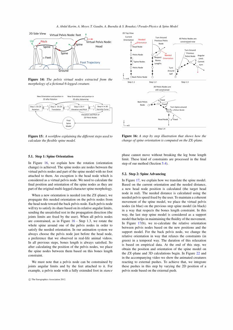
Figure 14: The pelvis virtual nodes extracted from themorphology of a fictional 6-legged creature.
Step 1: On ZX
Rotation
Step 2: On ZX
Translation
Step 4: In 3D
Hermite Curve
Step 3: On Y
Elevation and Pitch
Final
Spine
Model
New Orientation and position in
2D after Rotation
Elevation and Pitch of
2D Pelvis Nodes
New Orientation and position in
2D after Advancing
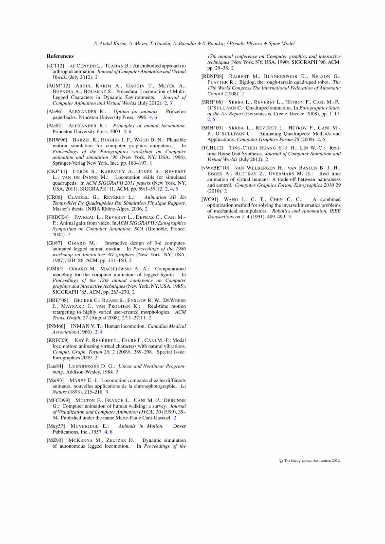
Figure 15: A workflow explaining the different steps used tocalculate the flexible spine model.
5.1. Step 1: Spine Orientation
In Figure 16, we explain how the rotation (orientationchange) is achieved. The spine nodes are nodes between thevirtual pelvis nodes and part of the spine model with no footattached to them. An exception is the head node which isconsidered as a virtual pelvis node. We need to calculate thefinal position and orientation of the spine nodes as they arepart of the original multi-legged character spine morphology.
When a new orientation is needed (on the ZX-plane), wepropagate this needed orientation on the pelvis nodes fromthe head node toward the back pelvis node. Each pelvis nodewill try to satisfy its share based on its relative angular limits,sending the unsatisfied rest in the propagation direction (thejoints limits are fixed by the user). When all pelvis nodesare constrained, as in Figure 16 - Step 1.3, we rotate thewhole spine around one of the pelvis nodes in order tosatisfy the needed orientation. In our animation system wealways choose the pelvis node just before the head node,a preference that we observed in real-life animal videos.In all previous steps, bones length is always satisfied. Soafter calculating the position of the pelvis nodes, we placethe spine nodes between them based on this bones lengthconstraint.
We must note that a pelvis node can be constrained byjoints angular limits and by the feet attached to it. Forexample, a pelvis node with a fully extended foot in stance
Head Node
Pelvis Node
Pelvis Node
Back Pelvis Node
Spine Nodes
Needed
Orientation
Turn Around
Previous Pelvis
Node
Turn Around
Previous
Pelvis Node Respect
Bones
Lengths
All Pelvis Nodes are
still constrained
Turn Spine around
a Pelvis Node
Head Node
Step 1.1 Step 1.2 Step 1.3
Needed
Orientation
X
Z
Back Pelvis
Node
Turn
Around
Self
Fixed
Fixed
Fixed
All Pelvis Nodes are
constrained now
Current
Orientation
X
Z
2D Top View
Angular
Limit:
Cannot
turn
Step 1.4
Figure 16: A step by step illustration that shows how thechange of spine orientation is computed on the ZX-plane.
phase cannot move without breaking the leg bone lengthlimit. These kind of constraints are processed in the finalstep of our method (Section 5.4).
5.2. Step 2: Spine Advancing
In Figure 17, we explain how we translate the spine model.Based on the current orientation and the needed distance,a new head node position is calculated (the target headnode in red). The needed distance is calculated using theneeded pelvis speed fixed by the user. To maintain a coherentmovement of the spine model, we place the virtual pelvisnodes (in blue) on the previous step spine model (in black)in a way that respects the bones length constraint. In thisway, the last step spine model is considered as a supportmodel that helps in maintaining the fluidity of the movement.In Figure 17(b), we re-calculate the relative orientationbetween pelvis nodes based on the new positions and thesupport model. For the back pelvis node, we change therelative orientation in way that relaxes the constraints (ingreen) in a temporal way. The duration of this relaxationis based on empirical data. At the end of this step, weobtain the position and orientation of the spine model onthe ZX-plane and 3D calculations begin. In Figure 22 andin the accompanying video we show the animated creaturesreacting to external pushes. To achieve that, we integratethese pushes in this step by varying the 2D position of apelvis node based on the external push.
c© The Eurographics Association 2012.

A. Abdul Karim, A. Meyer, T. Gaudin, A. Buendia & S. Bouakaz / Pseudo-Physics & Spine Model
X
Z
No change in
relative
orientation
Change in relative orientation
Head
Node
Back Pelvis Node
Target Head
Node
Length
Constraint
Change in
relative
orientation
a) b)
Pelvis
Node
Pelvis
Node
Back Pelvis Node
Place Spine Nodes
2D Top View
Target
Head
Node
Figure 17: Illustration on how we translate the pelvis andspine nodes, on the ZX-plane, based on the orientation andneeded distance.
5.3. Step 3: Spine Elevation and Pitch
As we decomposed the character pelvis into several virtualnodes, we decompose the height and pitch calculations intoits respective nodes, as shown in Figure 18. We integrate thepseudo physics system in each virtual pelvis nodes to addrealism to the spine model. By doing so, the final neededpelvis node elevation is calculated using the pseudo particle-based physics instead of the preferred height only. We mustemphasize that the final visual position of each pelvis nodeis independent from the height calculated by the pseudoparticle-based physics system. This is explained in the finalstep.
Foot Induced Pitch
Spine
Pelvis Node
Ground
Foot Induced
Pitch
Pseudo
Physics
Pseudo
Physics
Figure 18: Computation of each node’s height using thepseudo-physics system and computation of each virtualpelvis node pitch.
For the pitch angle of each pelvis node, we calculateit using the relative position of each foot. Let
−→Vi be the
vector that connects the current pelvis node with the footi (in orange in Figure 18). We calculate the perpendicularvector on
−→Vi in the direction of the creature progression. This
perpendicular vector represents how much this foot affectsthe pitch angle of its pelvis node. We call this perpendicularvector the foot induced pitch, and the final angle of the pelvisnode is an average of all the feet induced pitches.
5.4. Step 4: Final 3D Spine
Using the 2D positions calculated in Step 1-2 (Section 5.1& 5.2) and elevations calculated in Step 3 (Section 5.3), weobtain a preliminarily 3D position for each virtual pelvis
node. And using the 2D orientations calculated in Step 1-2and pitches calculated in Step 3, we obtain a preliminarilytangent direction for each of them. We construct a B-Spline(Hermite) curve between these 3D positions using theprevious tangents data. We sample this curve using thebones length constraint in order to calculate the final pelvisand spine nodes position and 3D orientation. By doing so,the visual representation of each pelvis node can have adifferent 3D position from the one calculated in the previoussteps. We consider the 3D positions calculated until Step 3as guidelines for the Hermite curve, making the pseudoparticle-based physics system independent from the visualsystem. Sometimes, the final position of the virtual pelvisnodes can not be satisfied by the CCD IK system becauseof joints constraints. In this case, Step 4 is repeated basedon the closer position that the IK system can ensure fromthe needed one. In Figure 19, we show the final generatedflexible spine model on an abstract lizard model. Its spineconsists of 3 pelvis nodes and 9 spine nodes.
2D Spine Model on
ZX-Plane
Final 3D Spine
Step1,2
2D Model
Sampled
Hermite
Curve
Pitch
Elevation Elevation
2D
ordination
Figure 19: Final generated flexible spine model in anabstract lizard model.
6. Results and Conclusion
In the accompanying video we show the capabilities ofour system in animating multi-legged characters in life-likeway using the components presented in this article. Finalsimulation is real-time (30fps) even with several creaturesat the same time.
In Figures 20, we show a frame by frame snapshot of awolf running with a gallop like gait. With the integration ofthe pseudo physics and the flexible spine, the wolf moves ina quite natural and life-like way, relatively similar to Figure 7and 12.
In Figures 21, we show a frame by frame snapshot ofa lizard running upward. By adding a visual yaw effect tothe spine model tangents, the animated lizard moves in abelievable way compared to a real life lizard. We calculatethe yaw value for each foot based on its current position (inwhite in Figures 21) and its rest position (in green). Thevalue of the final visual yaw effect is the average yaw forall feet.
c© The Eurographics Association 2012.

A. Abdul Karim, A. Meyer, T. Gaudin, A. Buendia & S. Bouakaz / Pseudo-Physics & Spine Model
In Figures 22, we show a frame by frame snapshot of awolf reacting to an external push. The presented spine modelis quite generic and capable of integrating external forcesin its own movement. These push forces are integrated inStep 3 (Section 5.3).
We presented two totally controllable components thatcan be added easily to any locomotion system in orderto generate believable and life-like locomotion animationsfor virtual creatures. The presented pseudo-physics systemand spine model use the minimum calculation possible inorder to generate the needed effects, without the need forcomplex physics or anatomic based simulations. We do notimplement any balance strategies when the system reacts toexternal pushes. Plus, there can be some leg intersection asour character controller generates the parabolic trajectoryof the feet with no special avoidance treatment. Addingthese balance strategies, using more morphology specific IKsystem and doing 3D planning for feet trajectory to avoidleg collision are our main focus in future works, as they addmore believability to the animated creatures.
Spine Pitch IK
Systems
a) b)
Figure 20: A wolf running to the left with its spine modelbeing deformed based on the pseudo physics and the pitchcontrol. a) 3D mesh. b) spine model and IK systems
Visual Yaw
Effect
Figure 21: A lizard running upward in a believable waycompared to a real life lizard, the top image is courtesyof [Mar93]. The visual yaw effect is calculated using thecurrent position of the feet on the ZX-Plane.
1) 2) 3)
4) 5) 6)
7) 8) 9)
Normal Run
Push
Starting Push
Integration
Back To
Normal Run
Figure 22: A wolf reacting to an external push on theshoulder level.
c© The Eurographics Association 2012.
A. Abdul Karim, A. Meyer, T. Gaudin, A. Buendia & S. Bouakaz / Pseudo-Physics & Spine Model
References[aCT12] AP CENYDD L., TEAHAN B.: An embodied approach to
arthropod animation. Journal of Computer Animation and VirtualWorlds (July 2012). 2
[AGM∗12] ABDUL KARIM A., GAUDIN T., MEYER A.,BUENDIA A., BOUAKAZ S.: Procedural Locomotion of Multi-Legged Characters in Dynamic Environments. Journal ofComputer Animation and Virtual Worlds (July 2012). 2, 3
[Ale96] ALEXANDER R.: Optima for animals. Princetonpaperbacks. Princeton University Press, 1996. 4, 6
[Ale03] ALEXANDER R.: Principles of animal locomotion.Princeton University Press, 2003. 4, 6
[BHW96] BARZEL R., HUGHES J. F., WOOD D. N.: Plausiblemotion simulation for computer graphics animation. InProceedings of the Eurographics workshop on Computeranimation and simulation ’96 (New York, NY, USA, 1996),Springer-Verlag New York, Inc., pp. 183–197. 1
[CKJ∗11] COROS S., KARPATHY A., JONES B., REVERETL., VAN DE PANNE M.: Locomotion skills for simulatedquadrupeds. In ACM SIGGRAPH 2011 papers (New York, NY,USA, 2011), SIGGRAPH ’11, ACM, pp. 59:1–59:12. 2, 4, 6
[CR06] CLAUZEL G., REVÉRET L.: Animation 3D EnTemps-Réel De Quadrupèdes Par Simulation Physique Rapport.Master’s thesis, INRIA Rhône-Alpes, 2006. 2
[FRDC04] FAVREAU L., REVERET L., DEPRAZ C., CANI M.-P.: Animal gaits from video. In ACM SIGGRAPH / EurographicsSymposium on Computer Animation, SCA (Grenoble, France,2004). 2
[Gir87] GIRARD M.: Interactive design of 3-d computer-animated legged animal motion. In Proceedings of the 1986workshop on Interactive 3D graphics (New York, NY, USA,1987), I3D ’86, ACM, pp. 131–150. 2
[GM85] GIRARD M., MACIEJEWSKI A. A.: Computationalmodeling for the computer animation of legged figures. InProceedings of the 12th annual conference on Computergraphics and interactive techniques (New York, NY, USA, 1985),SIGGRAPH ’85, ACM, pp. 263–270. 2
[HRE∗08] HECKER C., RAABE B., ENSLOW R. W., DEWEESEJ., MAYNARD J., VAN PROOIJEN K.: Real-time motionretargeting to highly varied user-created morphologies. ACMTrans. Graph. 27 (August 2008), 27:1–27:11. 2
[INM66] INMAN V. T.: Human locomotion. Canadian MedicalAssociation (1966). 2, 4
[KRFC09] KRY P., REVÉRET L., FAURE F., CANI M.-P.: Modallocomotion: animating virtual characters with natural vibrations.Comput. Graph. Forum 28, 2 (2009), 289–298. Special Issue:Eurographics 2009. 2
[Lue84] LUENBERGER D. G.: Linear and Nonlinear Program-ming. Addison-Wesley, 1984. 3
[Mar93] MAREY E.-J.: Locomotion comparée chez les différentsanimaux, nouvelles applications de la chronophotographie. LaNature (1893), 215–218. 9
[MFCD99] MULTON F., FRANCE L., CANI M.-P., DEBUNNEG.: Computer animation of human walking: a survey. Journalof Visualization and Computer Animation (JVCA) 10 (1999), 39–54. Published under the name Marie-Paule Cani-Gascuel. 2
[Muy57] MUYBRIDGE E.: Animals in Motion. DoverPublications, Inc., 1957. 4, 6
[MZ90] MCKENNA M., ZELTZER D.: Dynamic simulationof autonomous legged locomotion. In Proceedings of the
17th annual conference on Computer graphics and interactivetechniques (New York, NY, USA, 1990), SIGGRAPH ’90, ACM,pp. 29–38. 2
[RBNP08] RAIBERT M., BLANKESPOOR K., NELSON G.,PLAYTER R.: Bigdog, the rough-terrain quadruped robot. The17th World Congress The International Federation of AutomaticControl (2008). 2
[SRH∗08] SKRBA L., REVERET L., HÉTROY F., CANI M.-P.,O’SULLIVAN C.: Quadruped animation. In Eurographics State-of-the-Art Report (Hersonissos, Creete, Greece, 2008), pp. 1–17.2, 6
[SRH∗09] SKRBA L., REVERET L., HÉTROY F., CANI M.-P., O’SULLIVAN C.: Animating Quadrupeds: Methods andApplications. Computer Graphics Forum 28 (2009). 2, 6
[TCHL12] TING-CHIEH HUANG Y.-J. H., LIN W.-C.: Real-time Horse Gait Synthesis. Journal of Computer Animation andVirtual Worlds (July 2012). 2
[vWvBE∗10] VAN WELBERGEN H., VAN BASTEN B. J. H.,EGGES A., RUTTKAY Z., OVERMARS M. H.: Real timeanimation of virtual humans: A trade-off between naturalnessand control. Computer Graphics Forum, Eurographics 2010 29(2010). 2
[WC91] WANG L. C. T., CHEN C. C.: A combinedoptimization method for solving the inverse kinematics problemsof mechanical manipulators. Robotics and Automation, IEEETransactions on 7, 4 (1991), 489–499. 3
c© The Eurographics Association 2012.