generic equipment model (gem) specification manual: … · sematech technology transfer...
TRANSCRIPT

SEMATECHTechnology Transfer 97093366A-XFR
Generic Equipment Model (GEM)Specification Manual: The GEM
Specification as Viewed from theHost

SEMATECH and the SEMATECH logo are registered service marks of SEMATECH, Inc.
Product names and company names used in this publication are for identification purposes only and may be trademarks or servicemarks of their respective companies
Technology Transfer # 97093366A-XFRSEMATECH
December 31, 1997
Abstract: This document is designed to acquaint software engineers with the challenges and advantages ofimplementing the Generic Equipment Model (GEM) (SEMI standard E30) in semiconductorfactories. Written from the standpoint of a factory host computer, it is targeted especially forJapan’s semiconductor industry, which has not shown wide acceptance of GEM. It containsextensive GEM instructions, background, and scenarios. Appendix A includes the results of asurvey of Japanese manufacturers and suppliers regarding their interest in, and use of, GEM.
Keywords: CIM, Generic Equipment Model, Japan, Manufacturing Systems, Specifications, Standards
Authors: Kensuke Uriga, Texas Instruments/Japan
Approvals: Margaret Pratt, Project ManagerDan McGowan, Technical Information Transfer Team Leader


iii
Technology Transfer # 97093366A-XFR SEMATECH
Table of Contents
1 EXECUTIVE SUMMARY....................................................................................................... 1
2 INTRODUCTION..................................................................................................................... 1
3 PURPOSE OF THIS DOCUMENT.......................................................................................... 3
4 WHERE GEM FITS IN ............................................................................................................ 44.1 Scope of SECS-I, SECS-II, HSMS and GEM Implementations ..................................... 44.2 Interoperation of GEM, SECS-I, SECS-II and HSMS ..................................................... 5
5 BRINGING GEM ONLINE...................................................................................................... 75.1 Goals and effects............................................................................................................... 75.2 GEM and Factory Integration ........................................................................................... 95.3 GEM Compliance ........................................................................................................... 115.4 Installing GEM (Notes)................................................................................................... 145.5 Implementing GEM ........................................................................................................ 17
6 PRODUCTION MANAGEMENT SYSTEMS ...................................................................... 186.1 An Application Example of Bringing Equipment Online............................................... 18
7 EQUIPMENT OPERATION .................................................................................................. 277.1 Equipment Operation and GEM Capabilities ................................................................. 277.2 Equipment Operation Procedures ................................................................................... 297.3 Operational Design ......................................................................................................... 33
8 INDIVIDUAL GEM CAPABILITIES.................................................................................... 378.1 GEM Basic Prerequisites, Additional Capabilities, and Messages................................. 37
8.1.1 Basic Prerequisites ............................................................................................... 378.1.2 Basic Prerequisites/Additional Capabilities......................................................... 378.1.3 Additional Capabilities ........................................................................................ 378.1.4 GEM Capabilities and Messages ......................................................................... 38
8.2 Explanation of Basic Prerequisites ................................................................................. 388.2.1 State Model .......................................................................................................... 388.2.2 Equipment Processing Model .............................................................................. 398.2.3 Online Confirmation ............................................................................................ 448.2.4 Error Messages..................................................................................................... 458.2.5 Documentation ..................................................................................................... 45
8.3 Explanation of Basic Requirements and Additional Capabilities................................... 478.3.1 Host-initiated S1,F13/F14 Scenarios ................................................................... 478.3.2 Establishing Communications.............................................................................. 488.3.3 Control (Operator-driven) .................................................................................... 548.3.4 Control (Operator-driven or Host-driven)............................................................ 558.3.5 Event Reporting ................................................................................................... 648.3.6 Variable Event Data Collection ........................................................................... 68
8.4 Explanation of Additional Capabilities........................................................................... 708.4.1 Trace Data Collection .......................................................................................... 708.4.2 State Data Collection ........................................................................................... 718.4.3 Alarm Management.............................................................................................. 72

iv
SEMATECH Technology Transfer # 97093366A-XFR
8.4.4 Remote Control .................................................................................................... 738.4.5 Process Program Management............................................................................. 748.4.6 Material Transfer.................................................................................................. 788.4.7 Equipment Terminal Services.............................................................................. 788.4.8 Clock .................................................................................................................... 818.4.9 Spooling ............................................................................................................... 82
8.5 Compatibility Between Different Individual Capabilities .............................................. 848.5.1 Equipment Process States and Spooling .............................................................. 858.5.2 Equipment Process States and Remote Control................................................... 858.5.3 Equipment Process States and Event Notification............................................... 858.5.4 Equipment Process States and Control States...................................................... 868.5.5 Equipment Process States and Communications Establishment.......................... 878.5.6 Communications Establishment and Spooling .................................................... 878.5.7 Communications Establishment and Remote Control ......................................... 878.5.8 Communications Establishment and Event Reporting......................................... 888.5.9 Communications Establishment and Control States ............................................ 888.5.10 Control State and Spooling................................................................................ 888.5.11 Control State and Remote Control..................................................................... 888.5.12 Control State and Event Notification................................................................. 888.5.13 Event Notification and Spooling ....................................................................... 88
9 OTHER FEATURES .............................................................................................................. 899.1 Block Control Functions................................................................................................. 909.2 Material tracking............................................................................................................. 929.3 GEM and SEM................................................................................................................ 939.4 GEM and HSMS............................................................................................................. 93
10 CONCLUSIONS AND FINAL CONSIDERATIONS........................................................... 9410.1 In Closing........................................................................................................................ 9410.2 References....................................................................................................................... 94
APPENDIX A Survey Results—SEMI Japan Survey on SECS Implementation..................... 95

v
Technology Transfer # 97093366A-XFR SEMATECH
List of Figures
Figure 1 Postal System as a SECS Metaphor............................................................................. 5
Figure 2 Flow of Message Traffic Between Host and Equipment ............................................. 6
Figure 3 Operator-Mediated Integration..................................................................................... 9
Figure 4 Total Factory Integration............................................................................................ 10
Figure 5 GEM Capabilities and GEM Compliance.................................................................. 12
Figure 6 Expanding GEM Software ......................................................................................... 13
Figure 7 Structure of Equipment Controller Software ............................................................. 14
Figure 8 GEM and Multitasking............................................................................................... 15
Figure 9 Host Interface and User Interface............................................................................... 15
Figure 10 Equipment Control: the State Model ......................................................................... 16
Figure 11 Equipment Control in a Distributed, Multiprocessor Environment........................... 17
Figure 12 Process Management.................................................................................................. 19
Figure 13 Process Control and Process Supervision .................................................................. 20
Figure 14 Process Analysis......................................................................................................... 22
Figure 15 Process Diagnostics.................................................................................................... 23
Figure 16 Equipment Diagnostics .............................................................................................. 24
Figure 17 Host-Based Equipment Operating-Time Management.............................................. 24
Figure 18 Equipment-Based Operating-Time Management....................................................... 25
Figure 19 Remote Control .......................................................................................................... 26
Figure 20 Realtime Monitoring of Equipment Status ................................................................ 27
Figure 21 Equipment Operations and GEM Capabilities........................................................... 28
Figure 22 Online with Remote Control and Local Control........................................................ 35
Figure 23 E30 Equipment Processing Statechart ....................................................................... 40
Figure 24 Example of a Processing State Model........................................................................ 42
Figure 25 Simplified Example of a Processing State Model...................................................... 42
Figure 26 Depth of Equipment Processing Statechart Model .................................................... 43
Figure 27 Character-based Equipment Processing State Display............................................... 44
Figure 28 Communications State Model for Host-initiated S1, F13/F14 Scenarios.................. 47
Figure 29 E30 Communications Statechart................................................................................ 49
Figure 30 Communications State Settings Display.................................................................... 51
Figure 31 Communications State Setting with Process State and Control State Readouts........ 52

vi
SEMATECH Technology Transfer # 97093366A-XFR
Figure 32 Example of Establish Communications Timeout ...................................................... 52
Figure 33 Generalized Message-receipt Processing................................................................... 54
Figure 34 Control State Model That Satisfies Basic Requirements ........................................... 55
Figure 35 E30 Control State Model............................................................................................ 56
Figure 36 Sample of Setting of Default Control State ............................................................... 61
Figure 37 Sample of Control State Setup Screen ....................................................................... 62
Figure 38 Received Message Processing.................................................................................... 63
Figure 39 Sample of Variable ID List Display........................................................................... 66
Figure 40 Sample of Screen for Recording Report IDs.............................................................. 67
Figure 41 Sample of Report Control Screen .............................................................................. 67
Figure 42 Event-report Creation Mechanism............................................................................. 70
Figure 43 Relationship Between Events and Alarms ................................................................. 72
Figure 44 Recipe Editing Systems.............................................................................................. 77
Figure 45 Text-display/input Screen .......................................................................................... 79
Figure 46 The Host’s State Transitions During Online/Offline Switches.................................. 87
Figure 47 Event Reporting and Spooling ................................................................................... 89
Figure 48 Block Control............................................................................................................. 89
Figure 49 Where Block Controller Fits In.................................................................................. 90
Figure 50 Block Controller in a Distributed Processing System................................................ 91
Figure 51 Material tracking in the equipment ............................................................................ 92

vii
Technology Transfer # 97093366A-XFR SEMATECH
List of Tables
Table 1 Relations of Specific Actions to GEM Scenarios ...................................................... 29
Table 2 Equipment Parameters to be Stored in Nonvolatile Memory .................................... 31
Table 3 Host-Driven and Equipment-Driven Scenarios ......................................................... 34
Table 4 Patterns of Equipment Operations ............................................................................. 36
Table 5 Different Process-Start Scenarios .............................................................................. 37
Table 6 SECS Messages That Do Not Comply with GEM..................................................... 38
Table 7 Equipment operations under each control state ......................................................... 60
Table 8 Compatibility between individual capabilities (numbers show referencedsection) ....................................................................................................................... 85

viii
SEMATECH Technology Transfer # 97093366A-XFR
Acknowledgements
SEMATECH wishes to express its gratitude to Kensuke Uriga of Texas Instruments/Japan, whoauthored the Japanese version of this document; and to Adam Rice, who translated it intoEnglish.

ix
Technology Transfer # 97093366A-XFR SEMATECH
Preface
This document is a supplement to the Generic Equipment Model (SEMI Standard E30). Usinggeneral, common-sense language, it speaks to users seeking to implement GEM from a factoryhost computer. For proper understanding, the reader should be familiar with equipmentautomation (i.e, equipment networking); knowledge of E30 is desirable, but not essential.Although efforts have been made to ensure accuracy, this document may contain inadvertentcontradictions with E30.

x
SEMATECH Technology Transfer # 97093366A-XFR
Foreword
The author of this document is Kensuke Uriga, a systems integrator in Semiconductor CIMSystems at Texas Instruments/Japan. Since 1990, Mr. Uriga has supported various equipmentcommunications standardization efforts, including STEP/SECS and GEM.
Because Japan’s semiconductor industry offers few instructional materials and little training forSECS/GEM, Mr. Uriga felt it might be useful to write a document for equipment suppliers thatwould provide basic knowledge and requirements for GEM implementations, since hardwareengineers often lacked knowledge in production control, factory equipment control, and effectiveuse of equipment data. Also, the author believed that if equipment suppliers had generalknowledge about semiconductor manufacturing control, they would be able to develop morestandardized, sophisticated online specifications for their commercial equipment.
SEMI/Japan previously published Version 1.0 of this document in August 1994 and Version 2.0in December 1995, with the latter selling out of its 600 printed copies. (Mr. Uriga plans to writeVersion 3.0, which will contain major new requirements for standards, proposal and online fabrequirements.) Version 2.0, presented here in English with the author’s permission, can be usedby GEM “beginners” to obtain basic knowledge and requirements about GEM implementations.

1
Technology Transfer # 97093366A-XFR SEMATECH
1 EXECUTIVE SUMMARY
This document is designed for software engineers implementing the Generic Equipment Model(GEM) (SEMI Standard E30) for semiconductor manufacturers or equipment suppliers, and iswritten from the perspective of a factory host computer. Targeted especially for thesemiconductor industry in Japan, where GEM has been slow to gain acceptance, this report alsois meant to provide the concepts behind GEM and how to implement it.
The goals of this document include the following:
• Explicate required features at the host end, specifically regarding its interactionwith the client software
• Give the background behind each GEM capability, as well as reasons for theirinclusion, cautions on applying them, and illustrative samples
• Examine general scenarios for GEM application and explain the majorrequirements for GEM automation
• Clarify GEM’s features and show how GEM differs from messaging in SECS
• Examine functions not currently supported in GEM and show how GEM can beextended
There are many advantages associated with GEM compliant systems, including the following:
• GEM reduces equipment software development costs and improves functionalityand reliability by standardizing the host/equipment interface.
• GEM does not define a subset of SECS scenarios. It offers a uniform,systematized specification providing flexibility for host requests and equipmentfunctions.
• GEM is a technological foundation for future CIM in semiconductor fabs. Itallows for future expansion of capabilities.
GEM is the first state toward open semiconductor-CIM systems. As these CIM systems becomemore standardized, CIM software product lines that offer more flexible interfaces andconfigurations should become available. This will allow users to purchase software off the shelf,rather than creating it themselves.
2 INTRODUCTION
Work on GEM began in the U.S. in 1988, and in 1993, SEMI Standard E30 was approved. TheSEMI Japan communications committee worked closely with the SEMI USA communicationscommittee from the start.
At the time work on this project began, there were any number of obstacles to implementation.For instance, compared to the existing SECS standard, GEM required more sophisticated datamanagement. At the time, a lot of fabrication equipment ran on controllers meant for real-timecontrol to handle all control functions. It would be difficult to implement all their functionsstrictly as GEM functions. Also, GEM required that an advanced set of functions be immediately

2
SEMATECH Technology Transfer # 97093366A-XFR
available on the production floor, so both in terms of functionality and installation, GEMappeared problematic.
But the advent of cheap, powerful, and reliable PCs and workstations made them attractive foruse as the main controllers for fabrication equipment, which increasingly they are. From ahardware standpoint, modern computers have eliminated the constraints on GEMimplementation. Since these computers ordinarily have a multitasking operating system (OS),running GEM software likewise is no longer an issue.
Periodic software updates from the U.S. expand GEM’s base. With the active backing ofSEMATECH, a good number of fabrication equipment makers have signed on to support GEM.Naturally, chip makers have also requested that equipment manufacturers support GEM.
However, there are very few Japanese equipment makers supporting GEM, and when they do, itis generally in equipment destined for American chip makers. Almost no cases exist whereJapanese chip makers have requested that their equipment suppliers support GEM (seeAppendix A, “Survey Results—SEMI Japan Survey on SECS Implementation”).
Following are possible reasons behind the slow adoption of GEM in Japan:
• Implementing GEM would require the development or purchase of new softwareboth for the host and the fabrication equipment, and it is difficult to see how thecompany will recoup its initial investment in GEM.
• GEM has broader functionality than its precursor, the Semiconductor EquipmentCommunication Standard (SECS). Implementing GEM would therefore requiremore sophisticated software on the host machine.
• GEM is positioned chiefly as a data-processing standard, and is perceived ashaving inadequate transport system interfaces and material transport automationfunctions.
• The current host-equipment interface complies with an existing specification, soimplementing GEM offers few advantages except when bringing in newequipment. Furthermore, upgrading the existing hardware to GEM standardswould be problematic, both technically and financially.
• The perception exists that unless 80% of all equipment is upgraded to GEM, thereare no advantages to having GEM.
• Being a SEMATECH project, there is no central organization in Japan to backGEM.
In short, there are any number of reasons why GEM has been slow in being accepted in Japan.Moreover, GEM’s features and capabilities have been poorly explained to some extent, soinformation about GEM needs to be made clearer in the future.
In the U.S., though, the core of the GEM host-client interface is already in place, and the generaltrend is towards proceeding from there. As more and more equipment manufacturers,chipmakers, and software vendors begin to support and improve GEM, more software willbecome available that improves the performance and sophistication of GEM at a lower price.
Computer hardware and software is essentially growing standardized around the world now. Thishas created intense price competition both in the hardware and software markets, and prices

3
Technology Transfer # 97093366A-XFR SEMATECH
could yet drop quite a bit more. We may see the same sort of thing happen to CIM systems forsemiconductor fabs as well. Currently, most chipmakers are using custom software only usable intheir own operations, but this has limited reusability, and software development costs areexpected to tumble.
While the spread of GEM should result in cheaper client-side, GEM-compatible software,noncompatible software will probably stay at the same price, or even grow more expensive. Thiswill give those equipment makers and chipmakers who are using GEM an increasing costadvantage over those who are not.
Furthermore, GEM growing more prevalent will result in more software vendors developing anddistributing products that are compatible with GEM clients. Having a greater number of vendorsselling GEM software will drive software prices down and help to lower the price of GEMimplementation.
While the basic goal of GEM is to provide a standard communications interface for equipment,in the future this may be extended to components outside those in computer integratedmanufacturing (CIM) systems for semiconductor fabrication, such as process control systems,technical information control systems, and other major components. This will also allow them tointerface with the CIM system, ultimately enabling an open, distributed CIM system.
SEMATECH currently is working on a standards proposal for a semiconductor fab CIM systembased on object technology. It remains to be seen whether or not these standards will form aunified whole with GEM. GEM is not simply standardize individual pieces of equipment, it is amajor milestone on the road to creating a standardized, open CIM system for chip fabs.
3 PURPOSE OF THIS DOCUMENT
SEMI approved E30 in 1993. E30-1994 (E30 hereafter) is meant to be a reference model forimplementing a host-client interface protocol for users of E41 and E52.
This document is meant for software engineers implementing GEM for semiconductormanufacturers or equipment suppliers, and should help give a better idea of the concepts behindGEM and how to implement it.
The goals of this document are as follows:
• Explicate required features at the host end, specifically regarding its interactionwith the client software
• Give the background behind each GEM capability3, as well as their reasons forinclusion, cautions on applying them, and illustrative samples
• Examine general scenarios4 for GEM application and explain the majorrequirements for GEM automation
• Clarify GEM’s features and show how GEM differs from messaging in SECS
1 E4-91: semiconductor fabrication equipment standard 1: message transfer (SECS-I)2 E5-94: semiconductor fabrication equipment standard 1: message content (SECS-II)3 GEM capabilities indicate operations that are undertaken by fabrication equipment. For further details, see E30, “2. Definitions.”4 Scenarios showing the procedures for executing GEM capabilities are in the SECS-II message listing

4
SEMATECH Technology Transfer # 97093366A-XFR
• Examine functions not currently supported in GEM and show how GEM can beextended
To avoid overlap, anything that is explained in E30 will be omitted here. For this reason, thereader should consult E30 for clarification or details.
The client software features described herein are modeled on GEM. While GEM’s features canbe extended, this document omits any description of capabilities that seem to clearly contradictGEM. Although this document may extend beyond the scope of GEM in places, it shouldgenerally adhere to the GEM standard. Note that explanations of GEM extensions and conceptsnot clearly defined in GEM are the author’s opinions.
4 WHERE GEM FITS IN
This section shows how GEM relates to other communications protocols, and explains thepurpose of each protocol.
4.1 Scope of SECS-I, SECS-II, HSMS and GEM Implementations
The following list shows the differences between features and objectives in the variouscommunications protocols: SECS-I (SEMI E4); SECS-II (SEMI E5); HSMS (High Speed SECSMessage Service (HSMS) (SEMI E37-95); and GEM.
SECS-1This defines an transmission interface for passing messages between the fabrication equipmentand host. It specifies serial point-to-point communications, and covers the required connectors,signal levels, data rates, and logical protocols for passing messages back and forth (see E4-91).
SECS-IIDefines in detail the format for messages passing between the host and clients. Uses the messagetransfer protocol defined in SECS-I, but defines the form for messages passing between the hostand client equipment (see E5-94).
HSMSThis defines a transmission interface on the same level as SECS-I. This substitutes TCP/IP inplace of RS232C ports at 9600 bps. This allows transmission speeds in excess of 10 Mbps overEthernet.
GEMDefines a method for machine operations over a communications link. Defines specific functionsfor client machines, and specifies SECS message scenarios that will cause these operations toexecute. Although this does define specific operations for the client machines, it does notsimilarly define operations on the host machine (see E30).

5
Technology Transfer # 97093366A-XFR SEMATECH
4.2 Interoperation of GEM, SECS-I, SECS-II and HSMS
The postal metaphor: SECS-I and HSMS as a piece of mail. Figure 1 shows how SECSworks, using a postal metaphor. Assuming the address is correct and the necessary postage hasbeen affixed, then it should reach its intended recipient once it is put in a mailbox. The contentsof the letter do not matter: as long as the procedure has been followed correctly, there should beno obstacles to the letter getting through.
The address corresponds approximately to SECS-I or HSMS. In reality, the mechanism fordelivering the letter is equivalent to the physical network system and the transaction protocol,which are really what SECS-I and HSMS cover.
Figure 1 Postal System as a SECS Metaphor
SECS-II relates to the text, the message to be conveyed to the recipient. Conversely, SECS-IIrelates to the actual contents of the letter or postcard. SECS-II specifies the format of the text andthe minimal unit of meaning. In the same way that unreadable letters in the text would preventyou from understanding the contents of a letter, SECS-II gives a format that must be followed inorder for the information to pass back and forth correctly.
With regular mail, two different people might interpret the same text in different ways. Forexample, a recipient might be prompted to take some sort of action, depending on the contents ofthe letter, but the exact action taken might differ from between recipients. Likewise, SECS-IIdoes not specify the exact action that a recipient (or in this case, a client machine) should take.
GEM indicates the reader’s action or reaction. GEM is concerned with the traffic inspecialized messages (SECS-II transactions) and the particular actions taken upon their receipt.In the GEM universe, anybody reading a given letter should always take exactly the same actionin response. This assures that the sender’s intent will be properly conveyed to different recipients.
To carry the postal analogy a bit further, a GEM message—which might be likened to aChristmas card, an invitation, or a request for a favor—also carries with it a partial explanation ofthe intended action for the recipient. Neither the order in which all these letters are exchangednor the interrelationships among the actions they are meant to initiate are specified. These depend

6
SEMATECH Technology Transfer # 97093366A-XFR
on the people at both ends and the circumstances under which the letters were exchanged. InGEM terms, these depend on the plants and the message scenarios.
One purpose of these GEM guidelines is to clarify the way one should handle those things notspecified in a GEM message, such as message precedence and the interrelationships amongrecipients (equipment).
HSMS is for high-speed packets. In 1995, SEMI issued the HSMS Standard as a substitute forhigh-speed TCP/IP communications for the RS-232C serial communications in SECS-I. If onethinks of SECS-I as regular mail, then HSMS would be an express service. Since HSMS canhandle larger messages than SECS-I, it might be more appropriate to compare it to a courierservice.
The ability to transport larger messages was not the only change TCP/IP brought; it has had aconsiderable effect on the operation of production equipment. These effects will be discussedlater.
Message flow between equipment and host. Figure 2 shows the flow of message trafficbetween host and equipment, and the layered structure of SECS. Though the actual software isnot limited to this sort of implementation, this example is simplified for the purpose ofdiscussion. Following is an explanation of the order and layer in which messages are handled.
Applicationsoftware
GEM E30
SECS-II (E5)
SECS-IRS232C(E4)
HSMSTCP/IP(E37)
HOST
Figure 2 Flow of Message Traffic Between Host and Equipment
1. The host sends out the “establish communications request” (S1, F13) to the equipment.
2. This message is received at the SECS-I or HSMS layer and passed up to the SECS-II layer.If it is a multi-block messages, it may undergo block-deblock conversion here.
3. At the SECS-II layer, the equipment analyzes the format of the S1, F13 message, and ifthere are no problems with the message, it sends a message to establish communications upto the GEM layer. If there is a problem with the format, the SECS-II layer generates anappropriate error message and sends that down to the SECS-I/HSMS layer.

7
Technology Transfer # 97093366A-XFR SEMATECH
4. Having received the request to establish communications, the GEM layer executes a statetransition in accordance with the E30 communications model, and if everything is OK,sends a message corresponding to “communications request acknowledge” (S1, F14) downto the SECS-II layer. The GEM layer may also notify the application layer that it hasswitched into a communication state.
5. The SECS-II layer generates the S1, F14 message and passes it down to the SECS-I orHSMS layer.
6. The SECS-I or HSMS layer transmits the message to the host.
Assembling GEM scenarios is the job of the equipment’s application software. GEM doesnot yet specify the way in which individual capabilities should be bundled together into “onlineoperations” scenarios for every piece of equipment. This is a point to be investigated by GEMusers. In the example of Figure 2, the application layer supports actions for all the variousscenarios on that piece of equipment. Development of the application layer is the responsibilityof the equipment supplier.
5 BRINGING GEM ONLINE
This chapter will explain the objectives of bringing GEM online and the results of doing so, andwill discuss GEM features and conditions for GEM compliance.
5.1 Goals and effects
Compared to previous efforts, GEM specifies a more sophisticated standard for thehost/equipment interface. Following are some of the intended effects of GEM:
1. Reduce costs of developing client software
2. Improve reliability of client software
3. Improve the feature set of client software
4. Reduce the time to develop and implement plant-wide online systems
5. Improve the feature set of CIM systems
GEM’s external environment allows reuse of client-side SECS software. It was important thatGEM had a software development environment that gave equipment suppliers portable clientsoftware, for greater efficiency and a unified architecture. Implementing these internal andexternal environments helps achieve goal 1 of reduced development costs.
If the client software is portable, every piece of equipment can use the same kind of software.This vastly reduces the total number of updates that will be needed, and compared to thepre-GEM situation, dramatically improves reliability, thus achieving goal 2.
Since the client software is portable, developers need not reinvent the wheel each time they wantto implement a given feature for a different machine; their time can be dedicated to improving asingle client application. This contributes to realization of goals 1, 2, and 3. This also promptsequipment suppliers to place due emphasis on software development, which will further helptheir development programs by causing them to accurately forecast personnel and financialallocations for development.

8
SEMATECH Technology Transfer # 97093366A-XFR
GEM helps realize goal 4, of shortening the time to develop and implement an online system forfabrication equipment, because it vastly reduces the time to develop online specifications. Notethat even with GEM, there remains a great variety of operations for each piece of equipment, soGEM may not provide simple systems configuration for every piece of equipment. The host endalso requires a flexible software architecture.
In the initial phases of GEM implementation, the user still must develop new software, but atsome point in the implementation process, the effects of standardization will be seen. Until thathappens, however, ongoing investment will be needed in new client software, bringingstandardized host software online, and training and educating employees.
GEM brings the fifth goal of improving the CIM feature set through the cumulative effects of theprevious four. Raising the capabilities of CIM systems is the final goal of GEM.
Bringing GEM on line provides considerable savings by shortening the work of developinga client/host interface in automation projects. GEM provides nearly all functions needed tobring a plant online. Thus, in bringing fab equipment on line, you can provide the necessary levelof customization either through the GEM detail field or by developing functions that are notsupported in GEM. So compared with earlier, non-GEM-compliant equipment, the time todevelop a specification is reduced dramatically. And there is no need to develop a generalspecification for the host at all; only special aspects of the specifications need to be created,which further reduces labor.
GEM improves the equipment/host interface. GEM offers a more thorough set ofcommunications functions than plain SECS. It does not require that detailed specifications bedelivered to equipment suppliers. Functions can be added to the base provided by GEM ordeleted from it to provide just the needed ones.
The advantage of a global CIM system. If you are establishing a plant overseas, it makes senseto go with an international standard, as this will shorten development times, reduce expenses, andmake it easier to set up and maintain equipment.
Failure to standardize results in duplication of effort in development for hosts andequipment. Any number of semiconductor manufacturers have already developed proprietaryhost-client interface specifications. In some cases, a single manufacturer may have differentinterfaces at different fabs, even though the same types of equipment are in use.
Equipment vendors must revise and deliver client software that conforms to the interface dictatedby the semiconductor manufacturer. Taking the semiconductor industry as a whole, this couldultimately result in a total number of different versions of communications interfaces equal to theproduct of the number of equipment types multiplied by the number of semiconductormanufacturers (or perhaps even fabs).
This way of doing things looks at individual fabs as the unit within which standardization takesplace, and within which the developmental costs of host and equipment software are to becontained. But failure to standardize across an entire company, or indeed, across an industry,creates considerable inefficiencies in equipment development, and the semiconductormanufacturers, being the purchasers of this equipment, bear the cost. Furthermore, the client-endinterface must be able to accommodate revisions to the host software. This militates for astandard in communications interface software. Added software development costs for hostsoftware have similar implications.

9
Technology Transfer # 97093366A-XFR SEMATECH
The key to GEM’s success is in having a greater number of semiconductor manufacturers adoptthe GEM standard. The added costs created by the duplication of effort in software developmentwill be negated once more semiconductor and equipment manufacturers start using GEM. Thesesavings can be re-invested in developing products with greater added value.
5.2 GEM and Factory Integration
Factory integration and the client interface. The goal of factory integration is to get all theplant’s various subsystems working as a single system for the purposes of automation. GEM canbe considered as filling the equipment/host interface for integrating the host in an integrationprogram.
Take a look at Figure 3. In this example, there are three plant subsystems: host, equipment, andautomated material-transport system. In a factory that has not been fully integrated, the host,equipment, and automated material-transport system (which can be considered an interprocesstransport system) operate separately, and production only takes place through an operator’smediation. Figure 3 shows arrows pointing from each of the subsystems towards the operator, toindicate that operational requests go to the operator. The operator’s interface with each of thesubsystems is through some sort of a terminal, such as a CRT; the operator uses this to moveproduction along. Having production run by an operator puts a lot of flexibility into the system,and adequately covers shortfalls in the functionality of the subsystems.
Before factory integration
Operator
Host function for manufacturing
control
Function forautomated material
handling
Equipment functionfor materialprocessing
Figure 3 Operator-Mediated Integration
Figure 4 shows a completely integrated factory, in which host, production equipment, and theautomated transport system (which can be thought of as an intraprocess transport system here)are directly connected to one another. Rather than sending operational requests to an operator,each of the subsystems generates an “interface function request,” which is the basis forcoordinating activities. Compared with an operator-mediated arrangement, this directlyconnected arrangement has almost no flexibility—if there is even a minor crossup, the entiresystem might come to a halt.
The interface function request can technically accommodate just about any subsystem. If theothers can be made to accept the greatest number of functions possible, then one’s own load will

10
SEMATECH Technology Transfer # 97093366A-XFR
generally be lighter. Although this causes disputation among the staff, ultimately it leads to morerational decision-making.
For instance, the information required for online operation of a piece of equipment that isacquired through the user interface (e.g., lot information, recipe information, and other pieces ofinformation requiring operator confirmation), which would normally appear on the machine’sscreen, will often be handled as a part of the host’s production management functions. Whether amachine’s material process has ended, whether the input port has been cleared, and the like areoften handled as material request messages that the equipment sends to the host. Similarly, theman-machine interface, malfunction processing, and alarm-related interface function requests areall specific to the operation of a plant, and thus often differ from plant to plant.
After factory integration
Host function formanufacturing control
Functionfor automated
material handling
Equipment functionfor material processing
(GEM capability)
Requirementsfunction for
interface
Figure 4 Total Factory Integration
An equipment interface specification consists of equipment-based process functions,host-based operation functions, and material-transport functions. As previously stated, asystem for automating the production of semiconductors will comprise host, equipment, andtransport subsystems. Each of these subsystems has functions particular to their role, and willhave certain interface functions to enable automation. The exact interface functions will dependon which subsystem is connecting to which other subsystem, so the request specifications willvary accordingly. For example, when the host’s production management facility sends a requestto a specific piece of production equipment, the interface specification the host uses willnaturally differ depending on the specific process functions supported by the equipment.
For function requests from the host to be compatible with the production equipment interface, thesoftware that controls the production equipment’s interface with the host must be customized.Conversely, if one focuses on functions particular to a piece of wafer-processing equipment, boththe host and transport system must have their equipment interfaces customized in order tosupport all the production-management features in the host and transport automation functions inthe transport system.
Existing host-equipment communications interface specifications are customized forindividual semiconductor manufacturers. In general, when integrating equipment, thesemiconductor manufacturer tries to shape it to fit either its production-management system’sprocedures or its computer system’s functions. The equipment vendor will be expected to revise

11
Technology Transfer # 97093366A-XFR SEMATECH
its host-interface specification accordingly. These revisions essentially do not address functionsrelating to the actual processing of the wafer; rather, they generally cover how the host controlsand interfaces with the equipment. Since the equipment manufacturer has little experience andknowledge of these production management procedures, they follow the semiconductormanufacturer’s requested specifications for revised software. Naturally, the revisions are unique,and apart from host software, have almost no re-usability.
In extreme cases, the host computer has some sort of architectural or functional requirement thatforces the equipment manufacturer to support functions unrelated to their product. The point ofthis is to make development of the equipment interface specification simpler at the host end, andput more of a functional load on the client equipment.
GEM is not concerned with functions that do not relate to equipment processes, such asproduction management. It focuses solely on generalized automation and processing functions inequipment.
Doesn’t GEM have exact specifications for transport systems, operator interface, andproduction management? If GEM is already considered difficult enough, considering thecomplexity of its functions, then perhaps that is an excuse for saying so little about its productionmanagement, operator interface, and automated transport capabilities.
Host requests relating to production management and automated transport system requests willdiffer from fab to fab. Client equipment probably should deal with these requests to some extent,but the possible range is so broad that it currently would be difficult to develop a standard requestprotocol. As such, requests of this type are considered very little in GEM. Naturally, if it wouldbe possible to support a standard equipment request protocol shared by all equipment, it wouldbe a boon to production management, but it might not affect the equipment supported.
If, in the future, as ways are studied to standardize host and automated-transport interactionsalong a GEM-like model, it probably will be necessary to define a more exact request interfacefor dealing with equipment.
5.3 GEM Compliance
GEM compliance depends on satisfying the following conditions under E30, to support thecapabilities specified under GEM:
1. GEM’s basic requirements have been satisfied.
2. All relevant definitions, explanations, and necessary conditions as defined underE30 have been implemented.
3. Equipment capabilities have GEM-defined operations, and do not applycapabilities contrary to those actions.
Conversely, GEM is not concerned with capabilities implemented in GEM when they are beingused outside of a GEM context, e.g., when SECS-II messages are used outside GEM.
GEM contains basic requirements and additional capabilities. If the equipment implements thecapabilities in E30, then that equipment is considered to be GEM-compliant. To provide ayardstick for levels of GEM compliance, the terms basic prerequisite and additional capabilityare used here.

12
SEMATECH Technology Transfer # 97093366A-XFR
All basic requirements must be satisfied for GEM compliance. In order to ease GEMinstallation, the authors have narrowed down GEM’s basic requirements to a minimal set ofcapabilities. These are capabilities that can be implemented on any piece of productionequipment. Nevertheless, if even one basic prerequisite is not present, the machine is not GEMcompliant.
GEM’s basic requirements are not sufficient for achieving automation. Simply fulfillingGEM’s basic requirements will not be enough to achieve an automated system. The basicrequirements do not cover remote control or process program management. There will be anumber of situations where the required level of automation cannot be achieved using the basicrequirements.
Additional capabilities may be chosen à la carte. Given the different types of equipment andapproaches to automation found in different plants, the capabilities that GEM will be expected tosupport will also differ. Equipment manufacturers may select from among GEM’s additionalcapability set as fits their strategy; semiconductor manufacturers may also request them asneeded.
Failure to implement the complete E30 specification as-is will result in GEMnon-compliance. Supporting the alarm report under the alarm capabilities set, but failing tosupport the alarm enable/disable message could be said to be providing alarm capability supportbut would not be GEM compliant.
The relationship between GEM capabilities and GEM compliance. See Figure 5 tounderstand the relationship between GEM capabilities and GEM compliance.
Figure 5 GEM Capabilities and GEM Compliance
Complete GEM compliance does not restrict you from supporting other necessaryfunctions. GEM was designed to be generalized, supporting capabilities common acrossdifferent types of production equipment, but each type of equipment will have machine-specificcapabilities not specified under GEM. As previously mentioned, these capabilities can be treatedas either capability additions of capabilities not present in GEM or as capability extensions to

13
Technology Transfer # 97093366A-XFR SEMATECH
capabilities that are included in GEM. It also may be necessary to add capabilities outside GEMat the host end; this can be handled in a similar manner.
What is the difference between a capability extension and a capability addition? A capabilityaddition is defined here as any new capability not present in GEM. This might be the capabilityof the processing equipment to recognize a material ID code, which would involve a new type oftransaction between the equipment and host.
GEM extensions are ways of taking advantage of existing GEM capabilities in new ways.Consider this example: when equipment is switched online, it sends an F1, S1 message to thehost. Ordinarily, if there is not a response from the host within a set period of time, theequipment goes into offline. However, one could extend the equipment’s normal behavior byhaving it retransmit the S1, F1 message periodically until it receives the S1, F2 response. Thiswould be a capability extension.
GEM was designed from the ground up to allow for extensions to GEM software. The listbelow shows a taxonomy of GEM capabilities. These capabilities are all independent, and areconcerned with matters such as establishing communications or control.
1. A root part of the capabilities that cannot be altered or extended (except for revisions toE30).
2. User-defined parameter data, which can be used to change processing conditions.
3. A part for the functionality of existing capabilities to be extended through extensions.
4. A part for new capabilities, supporting functions not already a part of GEM, throughadditions. E30 itself may also be revised or expanded.
E30 only covers parts 1 and 2. Parts 3 and 4 were included to provide a mechanism for addingnew features during software development. Figure 6 shows the relationship between these parts.
Figure 6 Expanding GEM Software

14
SEMATECH Technology Transfer # 97093366A-XFR
5.4 Installing GEM (Notes)
There are aspects of both hardware and software configuration to take into account wheninstalling GEM on your equipment. This section explains some of those considerations.
Equipment systems configuration. The functions of the processing equipment, as viewed fromthe host, come in three broad types: Host Interface, Equipment Control, and User Interface. Therelationship between these three groups of functions is shown in Figure 7.
When establishing communications in GEM, there is the host interface, the user interface (whichcovers the setting of system constants and terminal support) and equipment control (which coversall other GEM capabilities). The role of process control is actually filled by the equipmentcontrol functions. Equipment control can also be taken to cover service functions for interfacewith other processing equipment, such as data logging.
The equipment itself may comprise hardware and software with greater complexity, but that willnot be handled here, as it involves the installation of device-specific controllers.
Legend
Hardware
SoftwareTransmission of informationrelating to GEM capability
User
Host
HostInterface
UserInterface
Equipmentcontrol
Equipment controller
Figure 7 Structure of Equipment Controller Software
GEM installation is compatible with a multitasking OS. GEM does not specify anyoperation-precedence or interrelationship between its individual capabilities; all its features canbe used independently of one another. Most of GEM’s capabilities can be executedsimultaneously and in parallel. As such, GEM is compatible with multitasking and distributedcomputing environments. This is an important advantage in helping you make the most of yourinvestment in expensive processing equipment.
For instance, this allows you to edit a process program while processing is underway, and havethe next recipe downloaded in advance. In order to take advantage of the independent operationof the host interface, user interface, and equipment control defined in GEM, a multitasking ordistributed environment, as depicted in Figure 8, is required.
A multitasking environment will also be beneficial in order to support such maintenance andservice functions as may be needed, but which are not defined in GEM. It would be difficult toimplement GEM in an environment where there is one CPU for every task.

15
Technology Transfer # 97093366A-XFR SEMATECH
Hardware
Software
Transmission of informationrelating to GEM capability
Host
Host interface
User interface
Equipment control
User
Equipment controller
Multi-tasking platform
Legend
Figure 8 GEM and Multitasking
Operations that can be conducted on the control panel also can be conducted from the host.GEM requires that any operation that can be conducted on the control panel also be available forcontrol from the host.
Figure 9 shows a schematic of how this would actually work. The heavy arrows show theequipment control interacting with the host interface and user interface, both of which use thesame format for control data. This design requires that both the user interface and the hostinterface have access to the exact same capabilities.
Henceforth, this document will not refer to the control panel at all, only to the user interface.
Host
Host interface
User interface
Equipment control
User
Legend
Hardware
Software
Transmission of informationrelating to GEM capability
Equipment controller
Figure 9 Host Interface and User Interface
The user interface is mediated through software. Given that operations originating from theuser interface and from host interface are treated in the same manner, the control panel (directlyconnected to the equipment control, used for input/output), consisting of physical switches, is
16
SEMATECH Technology Transfer # 97093366A-XFR
dispensed with in favor of a software-based system. This makes it possible to createuser-interface software that runs on a personal computer or workstation. Doing so would allowfor processing equipment with a simple control panel consisting only of a power switch,emergency shutdown button, and appropriate lamps and dials to confirm operational status.Another advantage is the ease of developing and maintaining the software-based interface.
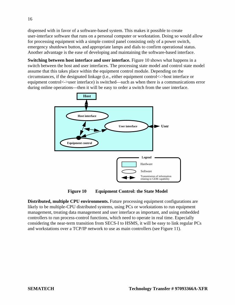
Switching between host interface and user interface. Figure 10 shows what happens in aswitch between the host and user interfaces. The processing state model and control state modelassume that this takes place within the equipment control module. Depending on thecircumstances, if the designated linkage (i.e., either equipment control<->host interface orequipment control<->user interface) is switched—such as when there is a communications errorduring online operations—then it will be easy to order a switch from the user interface.
Host
Host interface
User interface
Equipment control
User
Legend
Hardware
Software
Transmission of informationrelating to GEM capability
Figure 10 Equipment Control: the State Model
Distributed, multiple CPU environments. Future processing equipment configurations arelikely to be multiple-CPU distributed systems, using PCs or workstations to run equipmentmanagement, treating data management and user interface as important, and using embeddedcontrollers to run process-control functions, which need to operate in real time. Especiallyconsidering the near-term transition from SECS-I to HSMS, it will be easy to link regular PCsand workstations over a TCP/IP network to use as main controllers (see Figure 11).

17
Technology Transfer # 97093366A-XFR SEMATECH
Host
Equipment control
User
Legend
Hardware
Software
Transmission of informationrelating to GEM capability
Host interface
User interface
Equipment control
Nonvolatilememory
Main controller
Built-incontroller
Hardware (such as a PC)
Figure 11 Equipment Control in a Distributed, Multiprocessor Environment
Problems with current software development method; Guidelines for general equipmentsoftware design. Despite the fact that GEM promotes a standard equipment interface, there stillcould be unanticipated needs for new functions at the host end, or there may be a need for newfunctions in equipment processes. When this happens, they will simply need to be added in. Assuch, the equipment software should be structured so as to make additions and modificationseasier. The equipment software in use so far generally does not offer an easy way to deal withneeded revisions or modifications. This goes for GEM software, too—unless it offers someflexibility, then it will be difficult to implement previously unforeseen needs for the host.
The timing of SECS message transmissions and the data in those messages might be within theboundaries defined by GEM, but there could still be differences between types of machines orindividual users. Further, even supporting all the features currently in GEM within a single pieceof equipment software may not satisfy the needs of all users. Therefore, your softwarearchitecture should be sufficiently flexible to meet the differing demands of individual users.
5.5 Implementing GEM
Will GEM be harder to deploy in a plant that is already heavily automated andstandardized? Apart from the aspects of GEM that deal with automating material transport,GEM can support more functions than other communications interfaces commonly in use. It ispossible that if you have extensively automated and standardized your plant around proprietarytechnology that it will be harder to make the switch to GEM. Each plant that converts to GEMwill require different efforts to revise software and operating procedures for compatibility.Conversely, plants that have done little to standardize and automate their operations may be ableto bring GEM online more easily, as they have more flexibility.
The semiconductor industry has had stunning growth throughout Asia. Most Asian countrieshave less resistance to SEMI standards than Japan, and are implementing them more assiduously

18
SEMATECH Technology Transfer # 97093366A-XFR
than Japan. Indeed, the countries that have the least experience with automation would seem tohave the most to gain by adopting SEMI standards for communication and automation.
Equipment software price-setting strategy. GEM’s spread is helped by pricing. This list showshow the price-setting strategy for GEM software aids GEM’s popularization.
1. The initial development costs for installing GEM have been borne by equipmentmanufacturers, so individual semiconductor manufacturers do not need to absorb them.
2. The price of GEM-compliant equipment software is low.
3. The price of noncompliant software is higher (perhaps several times greater) than that ofGEM-compliant software.
4. The delivery times for noncompliant software are long. Since noncompliant software isbased on a unique specification, lead times can lengthen unpredictably.
5. GEM’s streamlined specification is amenable to expansion, which has beneficial costimplications.
Naturally, this strategy is not intended to prevent software from improving. The goal is to reducesoftware revisions that cater to the needs of only one customer.
Also, equipment manufacturers will still have good reason to keep some proprietarycommunications standards. Semiconductor manufacturers do not begin development of a newsystem from a blank slate—it would be best to adopt a standard that fits well with the company’sown specifications, which was the basis for this strategy.
6 PRODUCTION MANAGEMENT SYSTEMS
Understanding how GEM can be used as a part of a host-based production management system iskey to understanding the GEM specification in general. This section will give applicationexamples of bringing equipment online, and how GEM relates to the process. Note that by“host-based production management system,” does not necessarily mean standard, popularsystems. The model explained herein differs from the systems in current use in ways thatprobably cannot be reconciled.
6.1 An Application Example of Bringing Equipment Online
The GEM scenario has been adapted for the purposes of implementing SECS/GEM on the host.Below are some host-end management features that affect the GEM scenario.
The management features explained herein have intended relationships with SECS/GEMcapabilities. That is, this report will discuss only the functions achieved by bringing yourequipment online, and there will be some differences in the general management featuresrequired in semiconductor fabrication. Also, the functions described later can probably beimplemented even without SECS/GEM. Nevertheless, using SECS/GEM along with host-basedautomation software should offer a more efficient environment. This document will beexamining GEM-based automation with attention to its production-management functions.
Please note that although the hardware and software set-up you use for automating your facilitiesis an important topic, it will not be discussed in this document, since the range of possible set-upsis great—and more importantly, it does not directly relate to GEM.
19
Technology Transfer # 97093366A-XFR SEMATECH
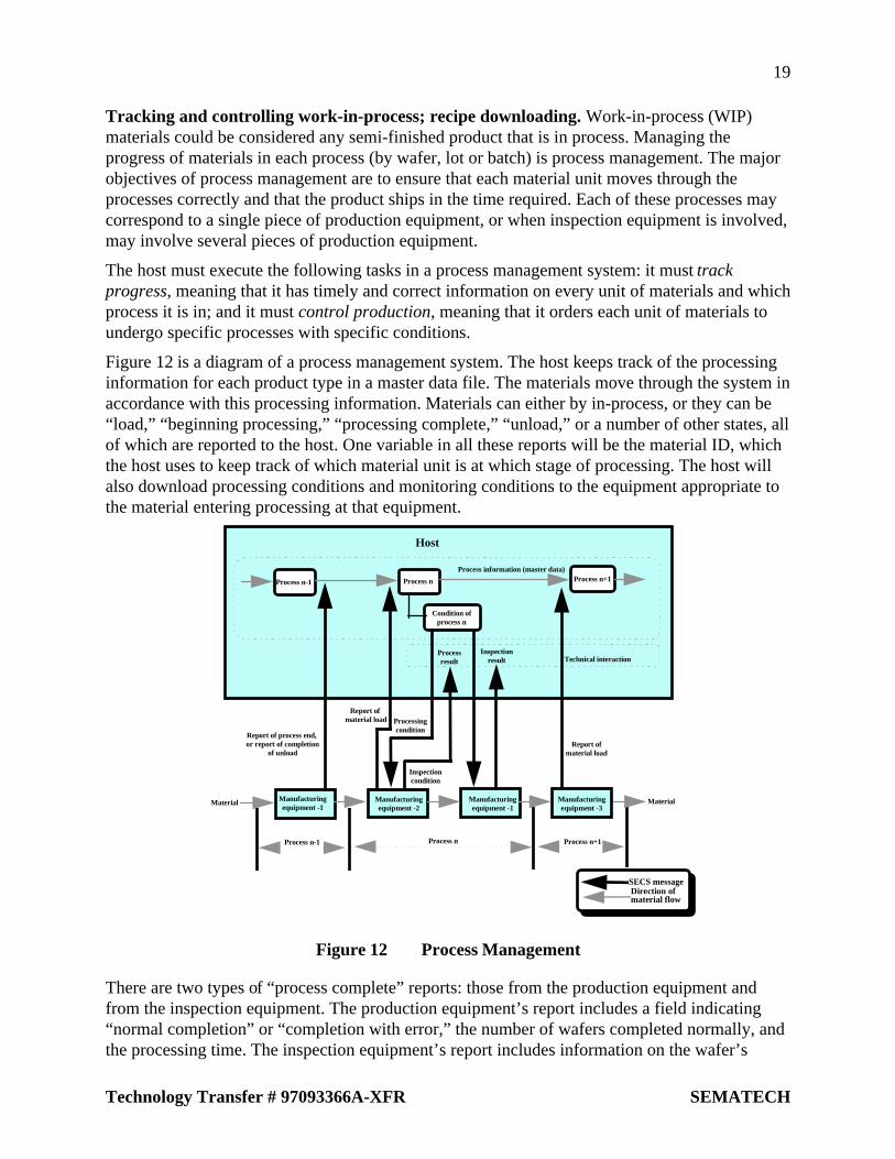
Tracking and controlling work-in-process; recipe downloading. Work-in-process (WIP)materials could be considered any semi-finished product that is in process. Managing theprogress of materials in each process (by wafer, lot or batch) is process management. The majorobjectives of process management are to ensure that each material unit moves through theprocesses correctly and that the product ships in the time required. Each of these processes maycorrespond to a single piece of production equipment, or when inspection equipment is involved,may involve several pieces of production equipment.
The host must execute the following tasks in a process management system: it must trackprogress, meaning that it has timely and correct information on every unit of materials and whichprocess it is in; and it must control production, meaning that it orders each unit of materials toundergo specific processes with specific conditions.
Figure 12 is a diagram of a process management system. The host keeps track of the processinginformation for each product type in a master data file. The materials move through the system inaccordance with this processing information. Materials can either by in-process, or they can be“load,” “beginning processing,” “processing complete,” “unload,” or a number of other states, allof which are reported to the host. One variable in all these reports will be the material ID, whichthe host uses to keep track of which material unit is at which stage of processing. The host willalso download processing conditions and monitoring conditions to the equipment appropriate tothe material entering processing at that equipment.
Process n-1 Process n Process n+1
Condition ofprocess n
Report of process end, or report of completion
of unload
Report of material load Processing
condition
Process n-1
Inspectioncondition
Report ofmaterial load
Material Manufacturingequipment -1
Manufacturingequipment -1
Manufacturingequipment -2
Manufacturingequipment -3
Material
Process n Process n+1
SECS messageDirection ofmaterial flow
Host
Process information (master data)
Processresult
Inspectionresult Technical interaction
Figure 12 Process Management
There are two types of “process complete” reports: those from the production equipment andfrom the inspection equipment. The production equipment’s report includes a field indicating“normal completion” or “completion with error,” the number of wafers completed normally, andthe processing time. The inspection equipment’s report includes information on the wafer’s

20
SEMATECH Technology Transfer # 97093366A-XFR
electrical characteristics and outward appearance. The host uses these two types of reports todetermine whether the material should progress to the next process or whether it should be sentback for rework. Depending on the process, information about the equipment itself may beexchanged, to aid in managing reticle information. Processing results and inspection results arehandled separately, and logged as technical information.
Bringing your equipment online automates the flow of data between the production equipmentand the host’s production management system. This can be used to prevent operator errors inrecipe downloading and reticle management. It also helps keep you accurately apprised ofprocess status, and simplifies process data collection. The GEM capabilities that pertain to thisare event reporting and process program management.
Process control/Process monitoring. Process control and process monitoring involve managingthe settings for processing parameters in each process and at each piece of equipment, classifiedby product. Further, it confirms whether the materials were properly processed according to thoseparameters, and decides whether the processing worked, allowing revisions to the processingconditions and feedback. The host is responsible for downloading all processing parameters,which will differ for each product and material, to the production equipment(“recipe” corresponds to process program in GEM/SECS-II). The host also collects processingresults and inspection results for all materials from the production and measurement equipment.
Figure 13 is a processing flowchart for process control. As previously mentioned, the host keepstrack of a master data file for all the processes involved in making every product. The master datafile will include target values with “management limits” (these target values are used both asgoals to be achieved in processing and in evaluating inspection results). The master data file willalso include reference parameters (recipe name), and various work orders for the operator. Thehost stores physical parameters (key recipe parameters) and process models for each procedureand piece of equipment. Since different products may use the same process technology,sometimes the same processing parameters can be re-used. The host consults the master data fileto select or generate the appropriate parameters, and download these parameters to the productionequipment in a process program.
HostProcess &
master data
Setting condition(recipe)
process model
Judgmentof process
result
Judgmentof process
resultNG
Processsuspended
NGProcesssuspended
Material
Setting of processingcondition
Setting of inspectioncondition
Reporting of inspectionreport
MaterialManufacturingequipment - 1
Manufacturingequipment - 2
Manufacturingequipment - 3
Manufacturingequipment - 4
Figure 13 Process Control and Process Supervision

21
Technology Transfer # 97093366A-XFR SEMATECH
It is important to collect process results data for each wafer that reflects the equipment and theprocesses involved in its production. Wafer process results data comes in two varieties: processresults are reported by the production equipment immediately after a process has been completed,and trace data is reported at regular intervals. The host compares these reports to its processmodel, and determines whether or not the reported data is within the management limits for theprocess. When the process results and the inspection results (collected from the inspectionequipment) both fall outside the management limits, material processing is suspended, andcorrective actions are taken (the recipe is revised, the equipment receives maintenance, etc.).Using the limit-monitoring capability in place of trace data may make it possible to determinewhether management limits are being exceeded at the equipment end.
There are a number of advantages to process control. Automating typical review and revisionprocedures helps to improve overall process performance. Some of the GEM capabilitiesinvolved at this level are event reporting, trace-data collection, and process-programmanagement.
Process analysis. The goals of process analysis are to 1) Ascertain production volume (capacity)and throughput; 2) Predict which processes will cause bottlenecks; 3) Predict cycle times. Thisinformation allows you to plan work-in-process insertions and set priorities for processes.
Semiconductor production involves hundreds of consecutive processes. The wafer must passthrough similar processes, each with minor variations in production parameters, in a specificorder. Several identical pieces of equipment can be grouped together, job-shop style, so thatprocesses are shared out among them. The production flow may have multiple configurations,depending on the product.
Ordinarily, the host will store management information on work-in-process in a database. Thiswork-in-process database would keep track of which materials were in which processes, and theirstatus. Figure 14 shows how this fits into a process analysis system. In reality, of course, thevarieties of equipment and processes would be more complex.
Bottlenecks occur at equipment groups with inadequate throughput. The reverse can also happen,where one equipment group has more capacity than is needed, which results in lower equipmentutilization rates.
Having equipment online provides the means to track, in real time, the time it takes materials topass through each process, using the material load, begin processing, processing complete, andmaterial unload event reports. If these reports are used to automatically update the WIP database,existing bottlenecks can be spotted quickly, and material status generally can be tracked morereadily.
For example, if there are 50 new lots per day, and there are 400 processes, then 20,000 processesper day are needed. If only the start and end of each process are tracked, then 40,000 transactionsper day are recorded. Having equipment online allows this vast quantity of information to becollected accurately and in real-time, without operator mediation.

22
SEMATECH Technology Transfer # 97093366A-XFR
Process-1
Host
Process-2 Process-3 Process-4
Process-5
Process-1
Process-6 Process-7 Process-8
Process-9 Process-10 Process-11 Process-12
Process-13 Process-14 Process-15 Process-16
WIP database
Processstart
Process end
Processstart
Processstart
Processstart
Process end Process end Process end
SECS messageDirection of material flow
ManufacturingEquipment-
Group 1
ManufacturingEquipment-
Group 2
ManufacturingEquipment-
Group 3
ManufacturingEquipment-
Group 4
Figure 14 Process Analysis
As previously discussed, semiconductor fabrication involves passing materials through the sameequipment group any number of times. This makes it extremely difficult to predict how WIPstatus might have changed at a given point in the future. With a WIP database that is beingupdated live with information from the production equipment, it becomes possible to use processsimulations and online scheduling make predictions about which processes will be bottlenecks,and based on these predictions, issue dispatches. The GEM capability at the core of all this iseven reporting.
Process diagnostics. Process diagnostics uses inspection data to determine whether eachprocedure is processing wafers at the needed level of accuracy, and whether there are problemsthat are pushing down yields. The object of process diagnostics is the shape of wafer patternings,chemical analysis data, etc.
Process diagnostics is often based on process capability, which uses numerically expressed data.Process capability is an overall measure of a the accuracy of a process—how close that processcame to meeting its management limits. Process capabilities usually need to be quite high inorder to achieve good yields, so process capability can be thought of as a yield indicator. Processcapability is discovered by statistic processing of a large quantity of inspection result data oneach process. The inspection result data is uploaded by the inspection equipment to the host overSECS lines, to be automatically integrated into a statistics management system, which makes itpossible to track process capability in real time. Refer to Figure 15.
Modern measuring equipment can capture visual data, detect particles at certain positions on thewafer surface, and also detect chemicals. Up until fairly recently, floppy disks could be used formoving and managing data, but this is another area in which SECS-I or HSMS are beneficial, by

23
Technology Transfer # 97093366A-XFR SEMATECH
automating and unifying data handling. As a wafer moves through all the processes involved inits production, a huge amount of inspection data is generated along the way. For a system to beable to handle this requires that both the production equipment and inspection equipment areonline, to facilitate the automated handling of measurement data. Event reporting is the key GEMcapability in process diagnostics.
Host
Technical Information Data
Statisticsprocessing
system
Output ofmanagementchart
Correlationanalysis
Inspection machine-1
Inspection machine-2
Inspectionmachine-1
Figure 15 Process Diagnostics
Equipment diagnostics & maintenance. Even a minor change in environmental conditions canhave serious effects on process capability in the manufacture of semiconductors, and of all theenvironmental factors, equipment condition is the one that has the greatest effect. Thus, it is veryimportant to be able to monitor equipment condition in real time, collect trouble data, run testsfor regular maintenance, and keep track of the number of wafers processed, to facilitatecomponent swapouts and cleaning.
Continuous monitoring of the frequency with which a piece of processing equipment reportsmajor alarms can help diagnose and predict equipment problems. SECS lines allow for theautomatic collection, logging, and analysis in this kind of situation, where there is a lot ofinformation (such as alarms) being generated in a short period of time. SECS lines also permitautomated logging and range-checking for equipment operating parameters that need to bemonitored in real time. Continuously tracking a large number of operational variables gives adeeper sense of equipment status and enables accurate equipment diagnostics. Importantequipment parameters need storage and statistical diagnostics, using SPC charts or othertechniques. Furthermore, automating the collection of equipment data and of decision algorithmscan dramatically reduce the overall work involved in equipment diagnostics. Refer to Figure 16.
An online system for processing equipment, necessary for continuous, statistical monitoring ofmultiple status variables, can be adapted to automate diagnostics to beneficial effect.Furthermore, the equipment data that is now output via a printer interface can be sent over SECSlines to the host to be managed as part of a unified system. The GEM capabilities that arerelevant to this task are event reporting, variable data collection, and alarm management.

24
SEMATECH Technology Transfer # 97093366A-XFR
Frequency of alarms?
Process condition?
Deterioration of parts?
How many wafersto be processed?
Result ofdaily maintenance? Alarm contents?
Host
Warning
Warning
Event report,variable data,or alarm
Data storage/statistics processing
Event report,variable data,or alarm
Manufacturingequipment - 1
Manufacturingequipment - 2
Manufacturingequipment - 3
Manufacturingequipment - 4
Manufacturingequipment - 5
Manufacturingequipment - 6
Manufacturingequipment - 7
Manufacturingequipment - 8
Figure 16 Equipment Diagnostics
Utilization monitoring. Utilization monitoring means knowing whether a piece of equipment isoperational or not, with the intention of increasing equipment availability. Operating timemanagement is an issue that E30 does not address, so few of GEM’s capabilities are directlyapplicable to this. Presently, most of the data relating to a machine’s operational state is collectedby the host-based management system, apart from the equipment.
Figure 17 is a diagram of an operating time management system, based on the SEMI E10specification for equipment operating states. The host compiles statistical data on equipmentstate transitions, from either event reports from equipment that uses this operating state model, ordirect operator input.
HostProduction
Preparation
Engineering
Scheduleddowntime
Unscheduleddowntime
Unscheduledtime
Report ofdown andprocessstart/stop
Report ofdown andprocessstart/end
Manufacturingequipment -1
Manufacturingequipment -2
Manufacturingequipment -3
Manufacturingequipment - 4
Manufacturingequipment - 6
Manufacturingequipment - 7
Manufacturingequipment - 5
Manufacturingequipment - 8
Figure 17 Host-Based Equipment Operating-Time Management
Operating-time management requires these functions from the system (the host and equipment):
• Substates to the equipment state, such as Processing and Ready, must have aninput method to cause state transitions relating to the equipment state ofequipment environmental variables. There must also be a way to display thisinformation for confirmation.
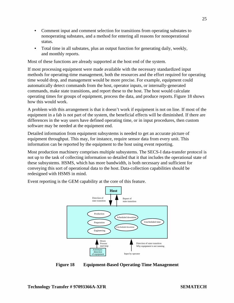
25
Technology Transfer # 97093366A-XFR SEMATECH
• Comment input and comment selection for transitions from operating substates tononoperating substates, and a method for entering all reasons for nonoperationalstatus.
• Total time in all substates, plus an output function for generating daily, weekly,and monthly reports.
Most of these functions are already supported at the host end of the system.
If most processing equipment were made available with the necessary standardized inputmethods for operating-time management, both the resources and the effort required for operatingtime would drop, and management would be more precise. For example, equipment couldautomatically detect commands from the host, operator inputs, or internally-generatedcommands, make state transitions, and report these to the host. The host would calculateoperating times for groups of equipment, process the data, and produce reports. Figure 18 showshow this would work.
A problem with this arrangement is that it doesn’t work if equipment is not on line. If most of theequipment in a fab is not part of the system, the beneficial effects will be diminished. If there aredifferences in the way users have defined operating time, or in input procedures, then customsoftware may be needed at the equipment end.
Detailed information from equipment subsystems is needed to get an accurate picture ofequipment throughput. This may, for instance, require sensor data from every unit. Thisinformation can be reported by the equipment to the host using event reporting.
Most production machinery comprises multiple subsystems. The SECS-I data-transfer protocol isnot up to the task of collecting information so detailed that it that includes the operational state ofthese subsystems. HSMS, which has more bandwidth, is both necessary and sufficient forconveying this sort of operational data to the host. Data-collection capabilities should beredesigned with HSMS in mind.
Event reporting is the GEM capability at the core of this feature.
Host
Production
Preparation
Engineering
Scheduled downtime
Unscheduled downtime
Unscheduled time
Direction of state transitionWhy equipment is not running
Input by operator
DownProcessstart/stop
Direction ofstate transition
Report ofstate transition
Automatic detection
of equipment
Figure 18 Equipment-Based Operating-Time Management

26
SEMATECH Technology Transfer # 97093366A-XFR
Automated material transport and remote control. “Remote control” means operationsexecuted by equipment at the command of the host. This is a necessary for running an automatedmaterial transport system of robots, automated guided vehicles (AGVs), etc. Figure 19 shows aschematic of how these systems work.
One condition for a remote-control system is that the host be running remote-control software.Ordinarily, this software is developed as part of a broader automation project. The software willgather material-transport reports and process-complete reports from production and inspectionequipment, and collect transport-complete reports from AGVs and the like via the automationsystem.
Whereas the production and inspection equipment accept process conditions and begin-processing commands (using the remote control capability), the automated transport systemaccepts transport-material commands. It also needs to accept recovery messages in troublesituations. Since the configuration of automated transport systems will vary from one fab to thenext, this is not yet an issue amenable to standardization.
Prompt pickup and delivery at the processing equipment is a key issue in automated transport,which requires accurate forecasts of processing times. Other important points are the ability todetect and recover from trouble situations; communications between the processing equipmentand transport system; and finally an interface between the two. The communications interface hasbeen defined in the E32-1994 standard, apart from GEM.
The GEM capabilities relevant to automated transport are material transfer, process programmanagement, remote control, event reporting, and alarm management.
HostProcess n
Condition ofprocess n
Remote control software
Input by operator
Directionof transfer
Completionof transfer
Process start
Process end
Report of material unloadReport of material load
Material Manufacturingequipment - 1
Manufacturingequipment - 2
Manufacturingequipment - 3
Manufacturingequipment - 4
Automatictransfersystem
Material
Sensing of processing conditions
Figure 19 Remote Control
Realtime monitoring of equipment status Continuously updating the host’s database with theinformation coming in via SECS connections allows you to track equipment operationsinformation in real time from any host terminal. For instance, a process engineer could checkrecipe data and current settings from his desk, or an equipment engineer could find out what theoperating statistics are for a machine, on-demand and right away. Production managers can checkthe operating parameters at any piece of equipment, whether any equipment is down, and get ageneral overview of current operating status in real time. Figure illustrates this capability.

27
Technology Transfer # 97093366A-XFR SEMATECH
GEM capabilities that come into play here are process program management, event reporting,status information collection, and alarm management.
Host
Condition of manufacturingequipment -n
Event report,variable data,or alarm
Event report,variable data,or alarm
Manufacturingequipment - 1
Manufacturingequipment - 2
Manufacturingequipment - 3
Manufacturingequipment - 4
Manufacturingequipment - 5
Manufacturingequipment - 6
Manufacturingequipment - 7
Manufacturingequipment - 8
Control condition
Process condition
Communication condition
Information toprocess material
Information toexecute recipe
Alarm condition
Status of process
achievement
Condition ofeach unit
Figure 20 Realtime Monitoring of Equipment Status
7 EQUIPMENT OPERATION
7.1 Equipment Operation and GEM Capabilities
Specific GEM capabilities relating to equipment operation are as follows:
1. Equipment start
2. Establish communications
3. Set control (set online)
4. Initialize equipment settings
5. Execute materials processing (includes multiple simultaneous processes)
Figure 21 shows the relationships between specific GEM operations and equipment operations.The vertical line on the left side of the figure represents the procedures relating to start-up andoperations. The left side of the figure shows a list of specific GEM capabilities. In most cases,these all can be executed in parallel when the equipment is in operation. After equipment startup,communications are established, and error-message capability is enabled. Shortly after controlstatus variables have been set, other GEM capabilities are activated. The capabilities activatedafter the control status are usually event settings, alarm on/off setting, time settings, equipmentpiece count setting, and spool parameter settings.

28
SEMATECH Technology Transfer # 97093366A-XFR
Shutdown
Startup of equipment
Establishmentof communication Error message
Setting of control
OFFLINEExecution of communication
Setting of events
Setting of time
Alarm valid/invalid
Setting ofequipment constants
Setting ofspooling condition
Simultaneous processing ofmultiple material processes
Completion/suspensionof process
Execution of material process
Setting of process condition
Setting of monitoring condition
Setting of recipe
Setting of trace condition
Setting of limit supervision
Setting of material ID
Remote start Stop/abort
Loss of communication
Process start/end
Figure 21 Equipment Operations and GEM Capabilities
Equipment operations and GEM scenarios. Table 1 shows in detail how specific actions atprocessing equipment relate to GEM scenarios. This example does not define the events or theorder of events in an action.

29
Technology Transfer # 97093366A-XFR SEMATECH
Table 1 Relations of Specific Actions to GEM Scenarios
Action Scenario Comment
Equipment start-up none Power supply turned on
Establish communications Host and equipment exchange S1,F13/14 messages
If successful, communications stategoes to “Communicating”
Request online Either S1, F1/F2 sent by the equipmentor S1, F17/18 sent by the host.
If successful, online status goes to“Online.”
Define events Host sends S2, F33/34, F35/35, orF37/38.
Defines event reporting. Need not berepeated after each restart once set.
Set time Either S2, F17/F8 sent by theequipment or S2, F31/32 sent by thehost.
Alarm on/off Host sends S5, F3/4 Need not be repeated after each restart,once set
Set equipment constants Host sends S2, F15/16
Set spool parameters Host sends S2, F43/44; F15/16 Need not be repeated after each restart,once set
Set recipe S7, Fxx sent between host andequipment
Exact operation will vary depending onwhether the recipe itself is normallydownloaded.
Set material ID Host sends S2, F41/42
Set trace parameters Host sends S2, F23/24 Trace begins when set
Set limit monitor on Host sends S2, F45/46 Need not be repeated after each restart,once set
Remote start/stop/abort Host orders S2, F41/42
7.2 Equipment Operation Procedures
Operations procedures should be understood in terms of the relationship between GEMcapabilities and equipment startup and actions. Operational procedures generally follows theflowchart shown below. This shows the GEM considerations and necessary parameters for eachstep.

30
SEMATECH Technology Transfer # 97093366A-XFR
Equipment start-up[Power on, reset, initialize]
↓Synchronization
[Establish communications, request online]↓
Preprocessing[Load material, set process program, tune processing parameters]
↓Process wafer
[“Process start” command, collect process data]↓
Postprocessing[Unload material, format collected process data]
↓Shutdown
Equipment startup. This involves switching on the primary power supply for a piece ofequipment and following the procedure for activating each of its subsystems. Since thisprocedure will be specific to the particular hardware/software configuration, it is not specified inGEM. In configurations where the actual equipment can be activated separately from the host-interface controller, communications between equipment and host may only be available once thehost-interface component has been activated, although if the processing equipment itself has notstarted up, then processing cannot begin, of course.
Equipment startup covers everything involved in bringing the equipment to standby status,including pump-up, gas supply/exhaust setup, etc.
The equipment may be in manual mode immediately after startup. In manual mode (standalonemode), all actions are executed by the operator manually. Communications status will be “notready.”
The communications protocol and all parameters defined in GEM become available justafter startup. Equipment parameters, which are all stored in nonvolatile memory, are availablejust after startup. This allows full synchronization with the host at startup time. If theseparameters can be wiped by resetting the machine, then the machine is not GEM-compliant.
Table 2 shows variable parameters that GEM expects to have stored in non-volatile memory.Constants of course should be stored in non-volatile memory; constants that need to be availableat startup are also shown for reference purposes.

31
Technology Transfer # 97093366A-XFR SEMATECH
Table 2 Equipment Parameters to be Stored in Nonvolatile Memory
GEM capability Parameter name Data description Comment
Establish communications Establish communicationstimeout (constant)
Establish communicationstimeout
Time in seconds withinwhich S1, F13 must be sentduring communications set-up
Control Control state duringequipment startup (constant)
Control State (variable) Online/offline
Online substate duringequipment startup (constant)
Control State (variable) Test equipmentonline/offline/host offline
Event reporting The S2, F37 “event-enable”parameter
Events Enabled reflected inenabled event CEID
Determines whether eventsare transmitted
The S2, F33 “define event”parameter
RPTID, VID Assigns an ID number to areport, as well as a VID forreport type number
The S2, F35 “link eventreport” parameter: event ID,report ID
CEID, VID Report ID linking to acollection event
Alarm management Alarms on/off Alarms Enabled reflected inenabled alarm ALID
Determines whether alarmsare transmitted
Limit monitor on All data defined by S2, F45,“define variable limitattribute”
VID, LIMITID, UPPERDB,LOWERDB
Defines limit-supervisionvariables and high-low limits
Spooling All data defined by S2, F43,“define spooling streams andfunctions”
STRID, FCNID Defines spooling messages
All constants and variablesrequired for spooling
MaxSpoolTransmit(constant) OverWriteSpool,SpoolCountActual,SpoolCountTotal,SpoolFullTime,SpoolStartTime
MaxSpoolTransmit sets S2,F15
Synchronization. This involves establishing communications between host and equipment, andsetting the control state.
In GEM, the communications state and control state are distinct. In previous host-equipmentcommunications schemes, the difference between the communication state and the control state(in which the host could run the equipment remotely) was not clear. In GEM, however, theconnection and initial relationship between equipment and host are defined in three distinctlevels:
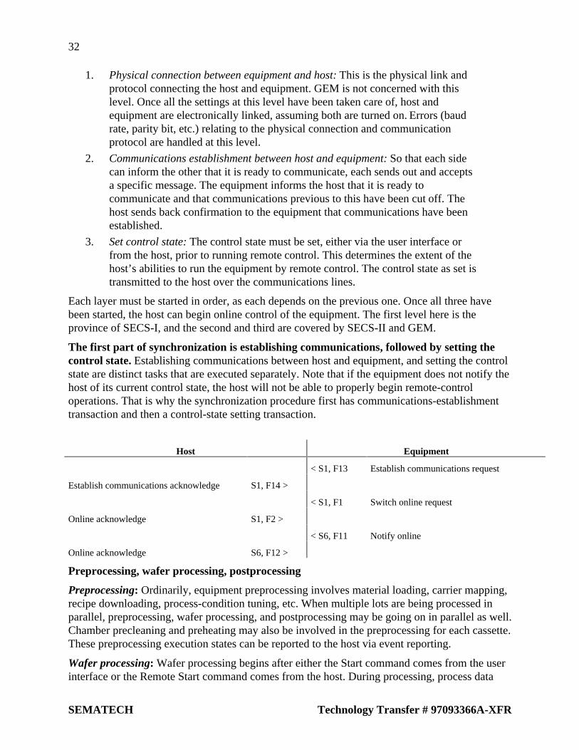
32
SEMATECH Technology Transfer # 97093366A-XFR
1. Physical connection between equipment and host: This is the physical link andprotocol connecting the host and equipment. GEM is not concerned with thislevel. Once all the settings at this level have been taken care of, host andequipment are electronically linked, assuming both are turned on. Errors (baudrate, parity bit, etc.) relating to the physical connection and communicationprotocol are handled at this level.
2. Communications establishment between host and equipment: So that each sidecan inform the other that it is ready to communicate, each sends out and acceptsa specific message. The equipment informs the host that it is ready tocommunicate and that communications previous to this have been cut off. Thehost sends back confirmation to the equipment that communications have beenestablished.
3. Set control state: The control state must be set, either via the user interface orfrom the host, prior to running remote control. This determines the extent of thehost’s abilities to run the equipment by remote control. The control state as set istransmitted to the host over the communications lines.
Each layer must be started in order, as each depends on the previous one. Once all three havebeen started, the host can begin online control of the equipment. The first level here is theprovince of SECS-I, and the second and third are covered by SECS-II and GEM.
The first part of synchronization is establishing communications, followed by setting thecontrol state. Establishing communications between host and equipment, and setting the controlstate are distinct tasks that are executed separately. Note that if the equipment does not notify thehost of its current control state, the host will not be able to properly begin remote-controloperations. That is why the synchronization procedure first has communications-establishmenttransaction and then a control-state setting transaction.
Host Equipment
< S1, F13 Establish communications request
Establish communications acknowledge S1, F14 >
< S1, F1 Switch online request
Online acknowledge S1, F2 >
< S6, F11 Notify online
Online acknowledge S6, F12 >
Preprocessing, wafer processing, postprocessing
Preprocessing: Ordinarily, equipment preprocessing involves material loading, carrier mapping,recipe downloading, process-condition tuning, etc. When multiple lots are being processed inparallel, preprocessing, wafer processing, and postprocessing may be going on in parallel as well.Chamber precleaning and preheating may also be involved in the preprocessing for each cassette.These preprocessing execution states can be reported to the host via event reporting.
Wafer processing: Wafer processing begins after either the Start command comes from the userinterface or the Remote Start command comes from the host. During processing, process data

33
Technology Transfer # 97093366A-XFR SEMATECH
(event reporting, trace data, limit monitoring, etc.) is relayed to the host. Process start, end, andinterrupt events must always be reported to the host.
Postprocessing: This involves material unloading and postcleaning. It is best to issue eventreports with accurate start and stop times for all of these processes, as these report make itpossible to monitor equipment status accurately and to perform statistical analysis ofoperating-time figures.
Shutdown. Shutdown involves powering-down the processing equipment and shutting down allof its functions. In processing equipment with built-in controller computers, this involvesshutting down that computer as well. It is best for the equipment to transmit a shutdown messageto the host at time of shutdown.
7.3 Operational Design
Each plant’s online operational style is going to be different, but they can generally bedivided into two categories:
1. Equipment-driven (online with local control): Here, the operator executes all actionsthrough the equipment’s user interface. The operator is also directly responsible for allmaterial loading.
2. Host-driven (online with remote control): Here, the host remotely orders all actions.The operator may be directly involved in material loading, or it may completelyroboticized.
Almost all fabs operate on one of these two plans, or some combination of the two.
Table 3 shows typical messages sequences of startup, begin processing, and processing complete,for both of these styles. The figure shows messaging in abbreviated form only, and does notcontain entire messaging scenarios.
It helps to think of operations as being host-driven or equipment-driven, as this clarifies thedivision of labor between the two—this division tends to be vague in most existing SECSscenarios. There tends to be a lack of coherence in operations and the design of messagesequences when an operation is sometimes conducted remotely and sometimes locally.
Thinking in terms of host-driven and equipment-driven operations allows organization ofmessage sequences into coherent scenarios, and it should be easier to make subsequent revisionsto message sequences. In the host-driven scenario in Table 3, the operator is responsible only forequipment startup and material loading/unloading; everything else is run from a host terminal. Inthe equipment-driven scenario, the operator executes all actions through the user interface.
Even in a host-driven setup, the equipment needs to be started up locally. That is why theestablish communications request and switch online request are usually both initiated by theequipment.

34
SEMATECH Technology Transfer # 97093366A-XFR
Table 3 Host-Driven and Equipment-Driven Scenarios
Host-driven scenario Equipment-driven scenario
Host Equipment Host Equipment
Est comm req S1, F13 > < S1, F13 Est comm req
< S1, F14 S1, F14 >
Online req S1, F17 > < S1, F1 Online req
< S1, F18 S1, F2 >
< S6, F11 Online rmt rpt < S6, F11 Online loc rpt
S6, F12 > S6, F12 >
Set time S2, F31 > < S2, F17 Set time
< S2, F32 S2, F18 >
Set alarm on S5, F3 > Set alarm on S5, F3 >
< S5, F4 < S5, F4
< S6, F11 Material set-up < S6, F11 Material set-up
S6, F12 > S6, F12 >
Download recipe S7, F3 > < S7, F5 Req recipe DL
< S7, F4 S7, F6 >
Req proc start S2, F41 > < S6, F11 Rpt proc start
< S2, F42 S6, F12 >
< S6, F11 Rpt proc complete < S6, F11 Rpt proc complete
S6, F12 > S6, F12 >
Remote control, and simplifying/standardizing equipment actions. Different kinds ofequipment will have different procedures for operations conducted via their user interfaces, butthese need to be standardized and simplified to facilitate remote operations by the host. Doing sohas a number of other benefits: it makes personnel transfers and new equipment investmentssmoother, and reduces the time required for and likelihood of error in programming.
Figure 22 shows the difference between local online control and remote online control. Atprocessing equipment #1 (online with local control), the operator requests processing parametersfrom the host, via the user interface, and then gives the order to begin processing. The materialID is entered via the user interface also. At processing equipment #2 (online, with remotecontrol), all actions taking place in the equipment are being ordered from a host terminal. Eacharrangement has its pros and cons.

35
Technology Transfer # 97093366A-XFR SEMATECH
HostProcess n
Condition ofprocess n
Requiring ofprocessing condition
Setting ofprocessing condition
Setting of processing condition
Remote control software
Terminal of equipment
Requiring ofprocessing condition
Process start
Input by operator(LOCAL)
Input by operator(REMOTE)
Terminal of Host
Requiring ofprocessing condition
Process start
Manufacturingequipment - 1
Manufacturingequipment - 2
SECS message
Remote log-in
Figure 22 Online with Remote Control and Local Control
Remote control is preferable for those aspects of operations that have a standardized, simplified,and interactive operator interface. The host terminal can provide its operator with a range ofservices needed for production management. For example, this arrangement provides instantaccess to the host’s database, which contains data useful for making decisions. Further, if theterminal can read the operator’s ID, it can be configured to show only the informationappropriate to that user. Remote control together with other GEM capabilities should allowalmost all equipment operations to be handled from the host. If the equipment’s software waswritten with GEM in mind, then host terminals should provide operators with sufficient remotecontrol over equipment capabilities. This allows an operator at one terminal to access the host atthe same time that he initiates an operation at the processing equipment. Furthermore, by usingHSMS (TCP/IP), equipment-based terminals may be able to remotely log in to the host—thiswould allow an equipment terminal to take on the function of a host terminal.
The main obstacle to remote operations is those plants that don’t have completely automatedtransport systems—in these cases, there need to be host terminals near every piece of processingequipment.
The other arrangement, with equipment being online but operated locally, allows operators towork at the equipment terminal, which increases performance. Nevertheless, if you upgradeequipment software to match plant operations, you will find that the initial development costsrise, that operator panels at each piece of equipment grows less and less alike (and harder to keepconsistent), and that there are limits on the ability to transmit interactive data by SECS-1.
Equipment that can be operated using fundamentally simple actions probably does not need ahost terminal present. If there is just a barcode reader for transmitting material IDs and operatorIDs to the host, the host may be able to handle all subsequent operations automatically. Thiswould fit in with a remote-control arrangement.

36
SEMATECH Technology Transfer # 97093366A-XFR
Notes on automated transport systems and patterns of equipment. It is helpful to organizemethod of equipment operations into a few general types, which range from standaloneoperations to fully automated operations:
1. All actions executed manually
2. Equipment is controlled through the host, except for material transport, whichthe operator handles manually. This approach also works with local onlineoperations, where the operator is executing actions through the equipment’s userinterface.
3. Equipment is controlled through the host, and material transport is completelyautomated through the use of robotics, etc.
These three schemes are summarized in Table 4. One can observe certain patterns in howoperating modes and operation types line up: the manual operating mode corresponds to thestandalone operation type, the automatic mode corresponds to the online operation type.
In types 2 and 3, having the automated transport off, communications state off, and control stateoffline would indicate either the startup operation or regular maintenance, but in any case,something other than regular operations.
Table 4 Patterns of Equipment Operations
Type 1 Type 2 Type 3
Material transport no no yes
Automated transport modes none none on/off
Operations modes manual automatic automatic
Communications states off on/off on/off
Control states none remote/local remote/local
Try to stay flexible, so that the order of execution for GEM capabilities fits with operatingscenarios. GEM places no restrictions on the order in which its various capabilities must beexecuted. In fact, almost all of them should be executable in parallel or in any order withoutcausing problems. Order of execution will be customized to fit the function of each piece ofequipment and the plant’s operating scenarios. You should set things up so that you can selectdifferent orders of execution on the equipment side. Although the host must be able to supplystandard GEM scenarios, the equipment must be amenable to revisions.
Examples of different process-start scenarios. Table 5 shows different process-start scenarios.In order to simplify the examples, some event reporting has been eliminated. In the“host-request” scenario, the host is aware of what kind of material is being transported, and hasalready downloaded the appropriate processing parameters to the equipment. If the equipmentwinds up not being set up for the expected materials, there will be some sort of error processing.
In the “equipment-dependent” scenario, the equipment can be set up for any kind of material.After the material has been loaded in the equipment, the host must be updated on the material IDand recipe ID by the equipment, after which it will acknowledge this information and downloadthe appropriate processing conditions.
One version of equipment software should be able to handle both of these arrangements.

37
Technology Transfer # 97093366A-XFR SEMATECH
Table 5 Different Process-Start Scenarios
Host-request scenario Equipment-dependent scenario
Host Equipment Host Equipment
Download recipe S7, F3 > < S6, F11 Material set-up
< S7, F4 S6, F12 >
< S6, F11 Material set-up < S7. F5 Req recipe DL
S6, F12 > S7, F6 >
Req proc start S2, F41 > < S6, F11 Rpt proc start
< S2, F42 S6, F12 >
< S6, F11 Rpt proc complete < S6, F11 Rpt proc complete
S6, F12 > S6, F12 >
8 INDIVIDUAL GEM CAPABILITIES
Following are the basic prerequisites and additional capabilities in GEM. The next section willexplain these capabilities in the order below.
8.1 GEM Basic Prerequisites, Additional Capabilities, and Messages
8.1.1 Basic Prerequisites
• State model• Equipment process model• Online acknowledgment• Error messages• Documentation
8.1.2 Basic Prerequisites/Additional Capabilities
• Host-initiated S1, F13/F14 scenarios• Communications acknowledgment• Control (operator-initiated)• Control (host-initiated)• Event reporting• Dynamic event report settings
8.1.3 Additional Capabilities
• Variable data collection• Trace data collection• State data collection• Alarm management• Remote control• Equipment settings

38
SEMATECH Technology Transfer # 97093366A-XFR
• Process program management• Material transport• Equipment terminal services• Clock• Remote monitoring5
• Spooling
8.1.4 GEM Capabilities and Messages
Newly-defined capabilities and messages for GEM: This is not anything you can find in theexisting SECS specifications, or any standard specification, so strictly speaking, GEM cannot becompared with SECS. Below are new or additional capabilities that have been defined for GEM.
• State model and equipment process model
• Host-initiated S1,F13/F14 scenarios
• Event notification and dynamic event report settings
• Control (operator- or host-initiated)
• Remote control
• Equipment terminal services (operator acknowledgment)
• Remote monitoring
• Spooling
Table 6 shows a breakdown of GEM-noncompliant messages (that is, messages newly definedfor GEM or duplicated in GEM) and compliant ones. This shows the original messages on theleft and GEM message substitutes on the right.
Table 6 SECS Messages That Do Not Comply with GEM
GEM capability Noncompliant message GEM substitute message
Event reporting S6, F3/F4
S6, F9/F10
S6, F11/F12
Variable data collection S6, F7/F8 S6, F15/F16
S6, F19/F20
Remote control S6, F27/F28
S6, F21/F22
S6, F41/F42
8.2 Explanation of Basic Prerequisites
8.2.1 State Model
The state model is the way to visibly express a device’s internal status or actions in GEM. TheHarel statechart is used as the state model notation. Please refer to Section 3 of E30, StateModels and Applications.
5 The description of remote monitoring in this document is abbreviated.

39
Technology Transfer # 97093366A-XFR SEMATECH
When implementing the capabilities described in the GEM state model, all functions must beimplemented as defined in the state model. Actually bringing the state model online should giveyou a better understanding of the correct procedures involved in transmitting messages, controlsequences, and equipment operations from the host.
The state model is a basic prerequisite: GEM uses the state model to describe the dynamicaspects of equipment capabilities. The state models needed to implement GEM’s basicprerequisites are the processing state model, the control state model, and the communicationsstate model.
State model expansions and GEM compliance: The state model may be expanded to supportexpanded GEM capabilities. As long as the original model is preserved and not interfered with,these expansions will still be GEM-compliant. GEM does not define a maintenance mode, aservice mode, or continuous/stepped processing sequences. The operational states needed for theactual performance of these are to be supplementally defined for each piece of equipment. Thisdocument has been expanded with this principle in mind.
8.2.2 Equipment Processing Model
The old host-equipment interface spec is inadequate for equipment operating states. Theequipment processing statechart must have a timetable of its internal processes so that the hostcan be kept current. It is difficult to achieve this—notifying the host of the equipment’s specificactions—using only existing host-equipment interface specifications (SECS). Interface softwarecan be developed that reports on the equipment’s order of operations, but this requires anengineer at the host and another at the equipment to go through repeated setups. Thoughtechnically speaking the communications interface can support it, it requires considerable work,increasing development time and lead time. Clearly, there is a lot of room for improvement.
The processing state model alone is not enough, but it is very helpful for the host-softwaredeveloper, in that it gives a better understanding of the equipment’s internal workings, and itgives a useful framework for deciding how to design the equipment interface.
The host’s interest is in changes of material state and changes of equipment state. The hostis mainly interested in two important processes in the equipment. One is the “change in materialstate,” that is, what happens as material is loaded in the equipment, subjected to certainprocesses, and then unloaded. The other is the “change in equipment state.” In this, it ismonitoring changes in the equipment’s state, according to material ID, as the equipmentsimultaneously processes several units of material. In some cases, this may also requiremonitoring of state changes in supplementary materials, as per a statechart. Tracking statechanges in the equipment may permit a single statechart for the entire apparatus, or it may requireseparate statecharts for each subsystem.
Goals for the equipment processing statechart. When writing host-end software, developersshould have possess certain knowledge sets, including the following:
• A comprehensive understanding of all equipment process actions
• An understanding of internal material-processing steps
• An understanding of state changes in the primary components of the equipment

40
SEMATECH Technology Transfer # 97093366A-XFR
• Knowledge of the transmission timing for process program downloads and remotecontrol commands.
• Knowledge of the timing when major events are generated, such as process-startand process-complete
Developers all should be prepared to conduct:
• An examination of recovery operations for errors
• An examination of event-collection timing for operating time statistics
Referring to the statechart, if one collects the event reports generated during the transitionperiods between states, then the host can track the equipment’s state in real time and transmit theproper action directives to it.
The statechart is not just documentation for its own sake. The equipment must run according tothe statechart.
Processing state models differ for each type of equipment. GEM does not define thesubstance of statechart: Figure 23 shows an equipment processing statechart from E30. Sincethe actual configuration of the equipment may be exceedingly complex, it can be difficult torepresent the processing states completely just using the statechart. While GEM does require theequipment supplier to document a processing statechart, it does not tell you what it should looklike.
INIT
IDLE
SETUP
READY
EXECUTING
PAUSE
PROCESS
PROCESSING ACTIVE
H#
Figure 23 E30 Equipment Processing Statechart
Additions to the state processing model: A processing statechart probably needs to include astatechart for input/output ports (including wafer/casette information) and process setup statetransitions. There are a number of processing state models, material state models, and port statemodels, which are desirable in that they allow the host to monitor the operating state of theequipment, what material is in transport or is being loaded, etc. And there need to be models thatdescribe the operational status of the equipment.

41
Technology Transfer # 97093366A-XFR SEMATECH
The scope of processing state models: The states and state transitions expressed in processingstate models will differ from one machine to another. However, all machines must support atleast the following states:
• Wait for operator command or host command, transition to next state upon receiptof command
• Currently executing a process internally, will generate event upon completion andtransition to next state
Figure 24 shows a model of this. The numbers in the figure represent the order of statetransitions.
1. Receipt of command from either operator or host to begin processing. If receivedfrom operator, a “processing start” event report is sent to the host.
2. Processing-start conditions are satisfied, so machine begins material processing.Event report sent to host.
3. Processing of one basic processing unit (a wafer, casette, etc.). is completed. Ifnecessary, process results and process completion are sent as an event report.
4. Processing of remaining material begins.
5. Processing of all material is completed. A processing-complete report is sent tohost. An event report with aggregate processing results is generated.
6. Receives “Pause” command from host or operator. Transition to Pause state,send event report.
7. Receives “Resume” from host or operator. Return to state preceding Pausecommand, send event report. If the previous state was Processing, the decisionof whether or not to return to the Processing state will differ from machine tomachine. For this example, we assume it can return.
8. Receives “Abort” from host or operator. Terminates processing, transitions toIdle state, and sends event report.
Thus, the processing state model expresses the relationships of states or state transitions to thehost or operator.

42
SEMATECH Technology Transfer # 97093366A-XFR
IDLE
READY
PROCESSING
PROCESSINGCOMPLETE
EXECUTING
PROCESSING ACTIVE
PAUSEH
1
2
3 4
5
6
7
8
7
Figure 24 Example of a Processing State Model
Internal transitions that do not concern the host are concealed. State model requirementsmostly consist of states and state transitions that the host needs to know about in order to managethe equipment. Internal state transitions that do not concern the host may be omitted. Acomplicated processing statechart would only serve to confuse things at the host end.
Consider Figure 24 again. Suppose the host is interested in knowing whether the equipment hascompleted processing of the last batch, and that it is not interested in tracking the processing ofindividual wafers or cassettes. If this is the case, then a state model as shown in Figure 25 wouldbe sufficient. Here, only transition 5 would generate an even report, once all materials had beenprocessed.
IDLE
READY
EXECUTING
PROCESS ACTIVE
H
1
2
5
6
7
8
PAUSE
Figure 25 Simplified Example of a Processing State Model
How detailed should be the processing state model provided by suppliers? Make a list of thefunctions provided by the equipment. Of these, the ones that the host would need to be able to

43
Technology Transfer # 97093366A-XFR SEMATECH
control will be considered pertinent to GEM. The processing state model should cover all statesrelated to the host interface that the equipment comprehends. Non-essential states may beremoved from the documentation (that is, concealed). Alternatively, it is advisable to give thehost some way to ignore them.
Figure 26 shows an example of this principle in action. The boxes represent a device, asubsystem, or a state. This roughly comprises the material transport input port, material transportunit, and processing chamber. A more detailed processing statechart would include all detailedstate transitions for the various subsystems. Depending on the type of equipment, the materialtransport unit and a single or multiple processing chambers may be combined into a singleprocessing statechart, the material transport input port statechart may be omitted, and the entirepiece of equipment boiled down to a single statechart. In any case, the criterion for inclusion in astatechart is whether an item can be monitored or sufficiently controlled by the host.
The heavy arrows in the diagram show the material transport path. The host is also concernedwith the various subsystems that the material passes through and the timing of these transfers(represented by arrows on dotted lines). These material transitions and the processes and statetransition models they entail are also useful to include.
Port 1 for material load/unload (state)
Port n for material load/unload (state)
Material transferunit (state)
Material processingand transfer (state)
Process chamber 1(state)
Process chamber n(state)
Material transfer route
Figure 26 Depth of Equipment Processing Statechart Model
Are there standards for processing state models? There are two approaches to the processingstate model: one is that regardless of equipment, the processing state model must comply withE30; the other is that different state models for each piece of equipment are acceptable.
Viewed from the host’s perspective, the processing state model holds that all pieces of equipmentcan be treated the same way. From the equipment’s perspective, the processing state model holdsthat depending on the type of equipment, there is a certain amount of flexibility available.
To satisfy both these approaches, it should be possible to use a multilevel approach to theprocessing state model, so that at the topmost level shows the host all of the equipment’suniversal processing state models. At the intermediate level, batch and single-wafer process typeswould appear, showing the different process types for the many different types of equipment. Atthe lowest level, every processing state that is comprehended by a certain piece of equipmentappears in the processing state model. This would go from the very abstract to the very specific,and if implemented, would allow the host and equipment to interact using the state model mostappropriate to the task at hand.

44
SEMATECH Technology Transfer # 97093366A-XFR
In this setup, the top level would be useful for the host collecting production management data,such as material processing states, processing parameters, loading capacity, and informationrelating to equipment utilization rates. The bottom level might reflect the equipment’s specificprocessing functions and hardware configuration in the state model.
Equipment processing state display. Although GEM does not define this, displaying thecurrent equipment processing state is going to be necessary. While the example shown here isdrawn from a character-based display, a graphical display would convey the information in amore understandable form.
Figure 27 Character-based Equipment Processing State Display
8.2.3 Online Confirmation
Online confirmation and control capabilities are interrelated. This sections examines thesecapabilities and how they are similar or different.
Issuing S1, F1 mean different things to the host and the equipment. When the host sends S1,F1 to confirm online, the equipment replies with S1, F2 and that is the end of it. If the equipmentgenerates the S1, F1 message, its significance is different from the same request when generatedby the host. While the host’s message is simply “confirm online,” the equipment’s version is“request confirm online.” The S1, F1 message as generated by the equipment is treated as acontrol capability.
The host can transmit S1, F1 at any time. The equipment can only issue the S1, F1 messagewhen it is set to the control state. The host, however, can generate this message anytime it needsto confirm online status.
Heartbeat monitoring. With this online confirmation function, the host can periodically sendthe S1, F1 message to the equipment to continuously monitor the equipment’s online status. Thisis called “heartbeat monitoring.” This is especially useful in plants where the material transport iscompletely automated or operators are otherwise not present at the equipment, as it allows realtime detection of irregularities with the equipment or the communications system.

45
Technology Transfer # 97093366A-XFR SEMATECH
8.2.4 Error Messages
Error message transmissions have priority over all equipment states. Assumingcommunications are operative, the equipment will inform the host of detected messages orcommunications irregularities using the error message suite (S9, Fx). If there is an interruption incommunications for example, regardless of online status or spooled action status, the equipmentwill notify the host when it detects an irregularity in the host’s messages by transmitting an errormessage. The error message capability has priority over other GEM capabilities. (See Figure 21,Equipment Operations and GEM Capabilities.”)
If the equipment receives messages it does not support from the host, should it respond tothe host with the Unrecognized error message? Messages will ordinarily be defined in thestandard, but if the equipment should encounter a message not internally defined, it should replyto the host with the “unrecognized stream” message (S9, F3) or the “unrecognized function”message (S9, F5). Note that as in the following example, when the procedure is defined in GEM,the equipment will follow it, even if it doesn’t support it.
Host Equipment
Transmit information S10, F5 >
< S10, F7 Multi-block not allowed
8.2.5 Documentation
What are the basic parameters for GEM documentation? Most existing host communicationsspecifications have inadequately specific descriptions, so it is difficult to properly understandequipment actions. Following are some guidelines for writing GEM documents. Please refer toSEMI document E30 as well.
• Equipment actions should be noted using the state model;
• Explain SECS-II messages;
• Note GEM compliance;
• Note all collection events for each piece of equipment, plus all conditions underwhich events are generated;
• Specify all limit-monitoring variables;
• Note and explain all state variables (SV), equipment constant values (ECV), datavalues (DVVAL), and variable IDs (VID);
• Explain all alarms, alarm IDs alarm texts, and alarm codes;
• Internal timing references should be in units of 0.01 second.
Items that should be defined in the host communications specification. Existinghost-communications interface specifications do not follow a common format, so everyequipment supplier must deal with a hodgepodge of styles. Following are some guidelines forwriting communications specifications.
1. Revision history
2. Contents

46
SEMATECH Technology Transfer # 97093366A-XFR
3. Applications. Specify objectives of the document and scope of applications.
4. Necessary items pertaining to SECS-I/HSMS. If you are compliant with SEMIstandards, you can omit the contents of “SEMI E4-1993.” etc., and merelymention them. This is the place to mention any important special items that needexplaining, such as message interleaving, multiplexed message checking,revisions to the message header transmitted by equipment, etc.
5. Notation of GEM compliance. Using the E30 GEM Compliance Sheet (E30Table 8.3), describe the level of GEM compliance. Also, explain anything elserelevant to GEM compliance here.
6. SECS-II message list
7. Variable parameters to be set. If there are any variable parameters relating toequipment-side communications, explain the setting procedure and how theyrelate to SECS-I, SECS-II and GEM here.
8. System overview, system configuration. Use a diagram to explain theequipment’s system configuration, including the controller, host interface, andautomated transport system interface. Also diagram the physical configuration ofthe unit and the input/output ports.
9. Equipment operations. Explain the equipment’s operation in easily understoodterms. This should cover lot makeup, unit of processing, lot insertion andextraction procedures, wafer processing pathways, preprocessing, dummy waferhandling, process program and recipe formats, variable-setting procedures, andfinally error processing. Explain the equipment’s operational modes usingprocess statecharts. Explain in detail statecharts, transition tables, eventreporting, and variables involving settings. Process chamber states, I/O portstates, material states, and the like must all be included as well. Explain in detailhow these states correspond to the actual circumstances of the equipment ormaterials, in a way that makes it easy for the host’s operator to visualize what isactually happening in the equipment. For GEM-compliant capabilities, it is OKto simply refer to “SEMI E30-1994 Compliance with the EstablishCommunications capability” and omit detailed descriptions of it.
10. Communications scenarios. Explain the communications scenarios somerepresentative operations. If it is easier to understand an explanation pitched interms of equipment operations, that is acceptable too. Although specificationwriters often just cover normal operations and omit any discussion of problemsituations, be sure to cover errors and error processing on the host.
11. Explanation of on-screen operations
12. Details of SECS-II message format
13. Overview of variables, collection events, and alarms

47
Technology Transfer # 97093366A-XFR SEMATECH
8.3 Explanation of Basic Requirements and Additional Capabilities
8.3.1 Host-initiated S1,F13/F14 Scenarios
In GEM, the Establish Communications capability is used to establish host-equipmentcommunications. This can be used for one to inform the other that there has been a period ofinterrupted communications. In order to establish communications, use the EstablishCommunications Request message.
There is a procedure for establishing communications when using basic requirements andwhen using additional capabilities. Using the basic requirements, the host can establishcommunications by sending the S1, F13 message. Using the additional capabilities, either thehost or the equipment can establish communications by issuing this message. Following is anexplanation of the various functions involved.
The host-initiated S1, F13/F14 scenario qualifies as a basic requirement. As previouslystated, either the host or the equipment can issue the S1, F13 message, and upon receipt of this,the other will respond with S1, F14. This establishes a line of communications. In order to keepthe procedure for setting up communications simple in GEM’s basic requirements, only the hostis required to be able to issue the S1, F13 message; the equipment need not be able to do so.
The communications model using the basic requirements. The basic requirements onlysupport communications establishment by the host. (See E30 4.1.5.1.) Figure 28 shows thecommunications state model. The diagram’s transition numbers correspond to the E30communications statechart. However, since the S1, F13 message is never sent to the host,handling of this message is omitted.
DISABLED
ENABLED
NOT COMMUNICATING
COMMUNICATING
Waiting for Completionof establishment of
communication(Send S1R14)
Waiting for Requestof establishment of
communication(Wait S1R13)
C
Figure 28 Communications State Model for Host-initiated S1, F13/F14 Scenarios
Under the basic requirements, the host issues the S1, F13 Establish CommunicationsRequest. The equipment responds with the S1, F14 Communications Online message. InFigure 28, if the equipment’s user interface is used to set the communications state to “enabled,”then the equipment first will go into a “waiting for communications establishment request” state

48
SEMATECH Technology Transfer # 97093366A-XFR
(WAIT S1, F13). Once the host has issued S1, F13, the equipment immediately responds withS1, F14.
Note that when the equipment’s communications state is “offline,” all messages (including thehost’s S1, F13) will be ignored. Also, when the equipment is in the “communications enabled”state, any message from the host other than S1, F13 will be ignored.
ENQ and ACK handshaking available even if state is Disabled. Communicationsestablishment uses the higher functions of the block transfer protocol. Accordingly, an electronicconnection between host and equipment is assumed to be enabled at all times. In theCommunications Disabled state, the equipment will receive the message, but will ignore it, andwill not send any reply to the host.
Under the basic requirements, there is no procedure by which equipment notifies the hostthat it has started up. Under the basic requirements, the equipment does not send the S1, F13message to the host. As such, even if the equipment controller has started up, there is no way ofconveying that information to the host. Likewise, until the host has sent the EstablishCommunications message to the equipment, there is no way for online operations to begin.
In order to deal with this, the operator must use a terminal to inform the host that the equipmenthas started up. In terms of automation, this would be considered extra work for the operator, andtherefore undesirable, so in actual implementation where automation was a priority, the basicrequirements alone would not provide a satisfactory way to establish communications.
The basic requirements do not implement spool capabilities. Under the basic requirementsmodel, the equipment does not issue the S1, F13 message, so despite knowing that the equipmentwill ignore all communications, there is no way to convey that to the host. As such, even if theequipment does support spooling, there would be no way for the host to initiate a spoolingtransfer or trigger the dropping of spooled messages. In short, if the communications model ofFigure 28 is in effect, spooling is impossible. In order to take advantage of spooling, theEstablish Communications capability must be able to use additional capabilities at the client end.
8.3.2 Establishing Communications
Under additional capabilities, either the host or the equipment can issue the S1, F13message independently. Figure 29 shows the E30 communications statechart. Ifcommunications are not in effect, then both the “host-initiated connection” or“equipment-initiated connection” are simultaneously available. In this model, both the host andequipment can set up communications in parallel, simultaneously. Please refer to E30 forexplanations of the transition numbers in the diagram.

49
Technology Transfer # 97093366A-XFR SEMATECH
DISABLED
ENABLED
C
NOT COMMUNICATING
COMMUNICATING
1
2 3
4
678
9
10
11 12
1314
Waiting for Requestof establishment of
communication
Waiting for completionof establisnment of
communication
Waiting for acknowledgement of
Request of establishment of communication
Delay timerwait for timeout
Figure 29 E30 Communications Statechart
Equipment that supports additional capabilities for communications establishment and alsosupports message interleaving can send out the S1, F13 message and accept the S1, F13 messagefrom the host immediately thereafter. In cases like this, where both sides receive the S1, F13message more or less simultaneously, both will respond with the S1, F14 message and thencommunications will be established. If the S1, F14 message is received before the equipment hasa chance to send out its own S1, F14 message, communications will be established at that time(the communications state is Communicating).
Host Equipment
Establish communications request S1, F13 > < S1 F13 Establish communications request
Establish communicationsacknowledge
S1, F14 > < S1, F14 Establish communicationsacknowledge
Communications establishment is completed once the equipment sends the host S1, F13.When the equipment sends the host S1, F13, the host responds with S1, F14, andcommunications are established. However, GEM in no way defines the capabilities of the host,so unless it is necessary, the host can drop its end of the S1, F13/F14 transaction in this case. Asimple equipment-initiated communications establishment scenario follows. Technically, this iscomplete once the equipment sends the S1, F13 message.
Host Equipment
< S1 F13 Establish communications request
Establish communicationsacknowledge
Communications established
S1, F14 >

50
SEMATECH Technology Transfer # 97093366A-XFR
When the equipment sends S1, F13 to the host, this should be interpreted as a recoveryfrom Not Communicating state. The equipment will never send the S1, F13 message to the hostexcept when it is in the Not Communicating state and it is trying to establish communications.As such, when the host receives the S1, F13 message, it should interpret that to mean that a NotCommunicating state exists. Having recognized a Not Communicating state, the proper responseis entirely the host’s responsibility. GEM specifies that, if necessary, the host should check if itcan begin transmitting spooled messages to the equipment. This will probably require that thehost confirm the equipment’s state information.
The host can check the communications state using S1, F13/F14. The host can issue theS1, F13 message any time it needs to check the communications state. When the equipmentreceives this message, it will reply with S1, F14 if it is already in the Communicating state. GEMdoes not specify that the communications-enabled equipment undertake any process in responseto S1, F13 other than replying with S1, F14. For example, if the equipment received S1, F13 itcould assume that the communications state was Not Communicating , but there is nospecification that the equipment should begin spooling.
GEM’s capabilities do not include the S2, F25/F26 loopback diagnostic request, so theS1, F13/F14 transaction’s usefulness is not limited to establishing communications, it is alsouseful for confirming communications.
On the other hand, the equipment can only use S1, F13 to establish communications with thehost.
Communications state settings display. The equipment’s screen should always display thecurrent communications state. In this example, the lower portion of the screen shows Disabled orEnabled, and if enabled, Communicating or Not Communicating. There also needs to be a switchto toggle between Enabled and Disabled.
Whether the Establish Communications operation is successful or more importantly if it fails,there needs to be a function providing feedback to the operator. In this document, an Alarmwindow is used for this purpose.
When the operator starts up the equipment, he or she can use this screen to set communicationsto Enabled. After the equipment goes through the Establish Communications procedure, thescreen will be updated with the new communications state.

51
Technology Transfer # 97093366A-XFR SEMATECH
Figure 30 Communications State Settings Display
Continuous communications-establish operations at the equipment. When thecommunications state is set to Enabled, the procedure to establish communications begins. Thiswill continue until communications have been established at the equipment and the state isCommunicating or until the state is Disabled.
Switching communications between Enabled/Disabled does not involve an event report.Regardless of the message, if communications are not enabled, the host will not be able totransmit it. When the operator sets communications to Enabled, an event report cannot be sent tothe host, as communications have not been established. Also, if the state is Communicating andis switched to Disabled, the new state is entered immediately, and again, an event report is notand cannot be sent.
Be careful about Enabled/Disabled switching during equipment operations. GEM allowsswitches between Enabled and Disabled at any time. Even during online operations, allcommunications can be halted by switching to Communications Disabled. Note that if thishappens accidentally during online operations, all messages subsequently sent from theequipment to the host will be lost. Even if spooling is supported, spooling will not be in effectwhen the communications state is Disabled. Take care to design the operator’s screen so that it isdifficult to accidentally or mistakenly switch communications to Disabled. In the sample screenbelow, the communications state setting is accompanied by processing state and control statereadouts, to remind the operator what is going on. Changing communications states while amaterial process is underway could bring up a window requiring confirmation to double-checkthe operator.

52
SEMATECH Technology Transfer # 97093366A-XFR
Figure 31 Communications State Setting with Process State and Control StateReadouts
Setting up the default settings and timeouts for the communications state. The defaultcommunications state can be switched between Enabled and Disabled. If the default is set toEnabled, the equipment will send an S1, F13 message to the host at the same time that its controlsystems come online.
Because the procedure to establish communications is meant run continuously, there is anEstablish Communications timeout, the duration of which can also be set. If anequipment-initiated attempt to establish communications has failed, S1, F13 will be transmittedagain after the period defined by this timeout. These values should be entered on the equipment’sscreen, a sample of which is shown here.
Figure 32 Example of Establish Communications Timeout
Only make the transition to the Not Communicating state when there has been acommunications failure. The only time that the communications state should go to NotCommunicating is when there has been a Communications Failure, as defined in SECS-I as the

53
Technology Transfer # 97093366A-XFR SEMATECH
inability to send a message for the RTY limit. This should not be used in the same way as theCommunications Fault, which is used for transaction timeouts.
A timeout in the S1, F13/F14 reply before communications have been established results ina Communications Failure. If the equipment detects a reply timeout when attempting toestablish communications using the S1, F13/F14 transaction, it enters S1, F13 retransmissionprocessing. In short, it considers this a Communications Failure.
A timeout in the S1, F13/F14 reply after communications have been established results in aCommunications Fault. If communications have already been established and thecommunications state is Communicating, then a timeout waiting for an S1, F14 reply to an S1,F13 message will result in a Communications Fault rather than a Communications Failure. Afault results in sending an S9, F9 Transaction Timeout message, rather than entering S1, F13retransmission processing. Following is a sample scenario.
Host Equipment
< S1 F13 Establish communications request
Establish communications request S1, F13 >
< S1, F14 Communications established
S1, F14 timeout detected
< S9, F9 Transaction timeout
When the communications state is Not Communicating, no processes are available exceptfor sending S1, F13 or replying with S1, F14. The equipment ignores all messages from thehost when it is Not Communicating except for S1, F13. Consequently, if it receives a messagefrom the host other than this, it need not respond with an Abort.
Even if the state is Not Communicating, if the equipment detects a format error in amessage from the host, it will execute error processing. If the equipment detects a format errorin a message received from the host, it immediately notifies the host with a system error message.Figure 33 is a flowchart showing the generalized message-receipt processing sequence.

54
SEMATECH Technology Transfer # 97093366A-XFR
Receives message
Communicationstate?
Valid
Checks format
Valid lower state?
Message?
Normal
COMMUNICATING
NOT COMMUNICATING
Invalid
Error
Abort message
Sends error message
Message?Other states S1F13
S1F14
S1F13
S1F14
Other states
Processing byother GEMcapabilities
Noprocessing
SendsS1F14
Communicationstate =
COMMUNICATING Aborts message
SendsS1F14
Communicationstate =
COMMUNICATING
Figure 33 Generalized Message-receipt Processing
The equipment will ignore messages saved from before communications went down. If theequipment detects a communications error, it switches states to Not Communicating and sendsS1, F13 to the host. Assuming this message arrives at the host intact, the host will reply with S1,F14. If the host already had another message in reply to something before communications wentdown, the host may or may not send that other message, but the equipment will ignore it if sent.
What happens when the equipment receives one message correctly but there is an error inthe second so it cannot transmit to the host? The equipment will execute the processesindicated by the first message. When the second message turns out to be impossible to transmit,the equipment goes through the procedure of establishing communications.
8.3.3 Control (Operator-driven)
Control capabilities can be driven from either the host or the equipment, so there must be away to make clear what the equipment is doing. Since control capabilities can be driven fromeither the equipment or the host, the division of responsibility must be made clear. After theequipment has started up and communications have been established, the control state is set toreflect control by the operator or the host.
Under the basic capabilities, the control state is set through the user interface. There arebasically three possible control states: Online Remote, Online Local, and Offline. Under GEM’sbasic capabilities, the control state is selected by the operator through the equipment’s userinterface (see E30 Application Note A6, “Examples of remote control applications.”) Theoperator functions covered by the basic functions are as follows:

55
Technology Transfer # 97093366A-XFR SEMATECH
• Operator-driven switch to online (basic requirement)
• Operator-driven switch to offline (basic requirement)
• Operator-driven switch between local and remote (basic requirement)
The control state model in the basic requirements. Figure 34 shows a control state model thatsatisfies the basic requirements. Transition numbers correspond to the state transition numbers inE30, Section 3.3, The Control State Model.
C
OFFLINE
ONLINE
C
C
EQUIPMENTOFFLINE
ATTEMPTONLINE
LOCAL
1
2
3
4 56
7
8
9REMOTE
Figure 34 Control State Model That Satisfies Basic Requirements
8.3.4 Control (Operator-driven or Host-driven)
This section describes control state selection and operation from the host’s perspective. Thecontrol substates will vary from one fab to another as appropriate to its equipment operations;what follows is an explanation of the control substates, using operational examples. Figure 35shows the control statechart as per E30 for reference purposes. Transition numbers correspond tothe state transition numbers in E30, Section 3.3, The Control State Model.

56
SEMATECH Technology Transfer # 97093366A-XFR
EQUIPMENTOFFLINE
ATTEMPTONLINE
HOSTOFFLINE
C
LOCAL REMOTE
OFFLINE
ONLINE
C
C
C
1
23
4
5
6
7
8
9
1011
12
Figure 35 E30 Control State Model
Online Remote state: The host can direct almost all equipment operations remotely. Thisprovides the functions needed if an automated transport system is in place. Even if there is noautomated transport system, this is useful when you wish to control equipment operationsthrough a host terminal.
Online Local state: The operator can execute almost all equipment operations through the userinterface. This is useful if the duties of the fab’s host are concentrated on production monitoringand data collection. It is also useful for specialized operations, where the parameters do notreside on the host, or when you want to monitor a trial run. Under online local control, theoperator enters the process parameters into the equipment through the user interface and directlyorders the equipment to begin processing. The host is scarcely involved in the processing, exceptfor being able to track it.
Online local control is also applicable to measuring equipment. Almost all normal measuringwork directly involves the operator. A measuring process program can be downloaded. Thiscollects the operations involved in the measurement terminal, which in many cases obviates theneed for a remote start order from the host. So it is possible to run measurement equipment underonline local control.
Note that when making use of host functions, for example, plotting the result of eachmeasurement on a totalizer chart, it may be advantageous to use online remote control: whenthere are errors that require the operator be notified, these can be handled through a host terminal.
Equipment Offline state: Use the offline state for equipment operations or maintenance thatinvolve absolutely no communications with the host. Placing the equipment in the offline state isone way to cut down dramatically on host-equipment message traffic.
Automated operations should be avoided at all costs in the offline state.

57
Technology Transfer # 97093366A-XFR SEMATECH
It is also possible to perform equipment maintenance while online, most likely in the online localstate. This allows the host to constantly monitor the equipment, tracking operating informationand the like. If in the online local state, the host will not issue any operation commands to theequipment, so there is little risk of receiving a mistaken command from the host. Once a piece ofequipment has been placed in service on a production line and is visible to the host, it is best tokeep it online.
Host Offline state: For one reason or another, the host may temporarily make a transition to astate that does not permit it to requests to switch online from the equipment. In this state, theequipment will wait until it receives a request to switch online from the host, or is switchedonline by the operator through the user interface.
The control state is set through the equipment’s user interface. Ordinarily, the operatorswitches the equipment’s control state through the user interface (S1, F1/F2). Regardless of thestate the equipment is already in, the state selected through the user interface takes priority.
Switching to an online state requires the host’s permission; switching offline does not. Inorder for the equipment to switch to an online state, it requires permission from the host (S1, F2),but it can switch offline on its own, without the host’s permission.
Note that the default control state to be entered at equipment startup can be set to online local oronline remote. If this is the case, the equipment will go into the online state without the host’spermission. With this procedure, even if the equipment does not notify the host by sending anonline event report because of a communications error, because the equipment is in an onlinestate, there may be a conflict.
If the host is offline, the equipment will wait for the host to request a switch to online.Although the control state is (switch online) set through the equipment’s user interface, the hostmay not be able to respond due to unforeseen circumstances. If the equipment is set forhost-driven control, and this problem makes it difficult to set the equipment to operator-drivencontrol, then wait for the host to recover. Once things on the host end are back in order, the hostwill send a request to switch online (S1, F17/F18). At this time, if the equipment was in the HostOffline state, it will switch online. Following is a sample message sequence.
Host Equipment
< S1 F1 Request online
Online request denied S1, F10 > transition to Host Offline state
(no event report issued)
Online operations enabled state
Request online S1, F17 >
< S1, F18 Acknowledge switch online
< S6, F11 Online event report
Event confirmed S6, F12 >
This allows the host to be started up after the equipment without requiring that an operator goaround and manually set each piece of equipment to the Online state. The Host Offline state isuseful if the host drops out of online operations for some reason, or if there is a need to take the

58
SEMATECH Technology Transfer # 97093366A-XFR
equipment temporarily offline. In these instances, the host sends a request to switch offline (S1,F15/F16) to the equipment. Note that the Host Offline state does not really mean that the hostreally is offline, but that the equipment should treat the host as if it were offline.
Another possible operating procedure might involve the equipment trying to establishcommunications immediately after startup, but with the host going into an offline state after this.The equipment would then wait for the host to request a switch online. If you have set up themessaging sequence so that once communications have been established, the host will alwayssend S1, F17, then the operator will not need to manually switch online.
Can the equipment run in the Host Offline state? GEM does not specify this. However, onceoperations have commenced in a certain operating state, the equipment may deny the host’srequest to switch online. In the Host Offline state, it may not be possible for the host to knowwhat the equipment’s operating state is, so if you permit the equipment to begin operations in theHost Offline state, it is possible that using only the SECS functions still available will beinsufficient for ascertaining the timing of a switch to an online state.
Differences between Online Local and Online Remote:
Online Remote: All command operations originate with the host. All aspects of the equipment’soperation can be controlled remotely without direct operator intervention, but the operator canchange parameters and other settings through the equipment’s user interface when needed. Thisstate is best used when conveyances are automated. The automated transport system should fit inwith the equipment and process materials. Online local control may also be a possibility forentering commands directly in the equipment, without using the SECS interface.
Online Local: The operator enters parameters, start commands, and all other operations directlythrough the user interface. The host’s duties are to monitor actions, but not to control theequipment. Starting operations remotely would not be possible, although downloadingparameters, etc., would be possible.
Automated processing can run under either the Online Local or Online Remote state.Normal equipment operations can be executed in either of these states. These correspond to thetwo types of operational modes in the explanation of plant automation concepts, whereOperational mode 1 would be Online Local and Operational mode 2 would be Online Remote. Itmay also be possible to combine these two modes.
Equipment operation in an offline state should be avoided as much as possible, as the host cannotensure the accuracy of the parameter settings in the equipment or monitor the equipment’soperations.
The difference between Online Local and Online Remote is in the command to beginoperations. The basic difference between these two states is whether physical operations in theequipment, such as begin processing or stop processing, can be ordered remotely. Remotecommands will only be accepted in the Online Remote state, not in Online Local. Apart fromremote commands, all SECS messages should in principle be handled the same way regardless ofstate. Following are typical scenarios.

59
Technology Transfer # 97093366A-XFR SEMATECH
Online Remote
Host Equipment
Send command S2, F41 >
< S2, F42 Acknowledge command
< S6, F11 Report process start
Start acknowledged S6, F12 >
Online local
Host Equipment
< S6, F11 Report process start input byoperator-initiated command
Input acknowledged S6, F12 >
< S6, F11 Report process start
Start acknowledged S6, F12 >
There can be restrictions placed on what operations can be ordered through theequipment’s user interface when in Online Local. It may also happen that the order ofoperations changes due to changes in operations years after operations have commenced, so theserestrictions can be a handy way of dealing with variable settings. Restricting the input of settingscould be on a command-by-command basis, or simply lock out the entire screen.
Assuming that the equipment supports remote execution of all functions, the user interface couldbe made almost completely superfluous. The switches available to the operator could berestricted to Emergency Stop, Stop, Abort, and other emergency-related functions.
Operations in Online Local are no different from operations in Offline. Since all operationsin Online Local are operator-driven, they are handled in the same manner as operations inOffline. The same operations that can executed by the operator in Offline must be executed in thesame way in Online Local. There might be no visible differences between operations in the twostates.
Indicate when the ranges of operations available in online and offline states are notidentical. There should be a clear explanation in the specifications of operations that areavailable through the user interface Offline, but restricted in an online state (either local orremote). While it is reasonable to expect some procedural differences between online and offlineoperations, it is best to keep things as similar as possible, except for functions relatingspecifically to remote control.
It is best to make all normal operations available while online. Automated equipment willnormally be run in an online state. Even during maintenance, or for operations run through theuser interface, it is best to run all operations in an online state. Everyday operations, includingrecoveries from minor troubles, can cause problems if there are constant switches between onlineand offline states.
Switching offline can cause serious errors, either for the host or the equipment. Switch offlineonly when it is impossible to continue operating online.

60
SEMATECH Technology Transfer # 97093366A-XFR
Online Local is appropriate for use in recovery mode from equipment problems. Aspreviously explained, when equipment problems arise, sometimes the recovery procedurerequires dropping Offline, but since the procedure for switching between online and offline statesis complex and time-consuming, it is best to avoid switching too frequently. If commands fromthe host cannot be accepted, switch the control state to Online Local. This should allow necessaryrecovery actions in recovery and at the same time generate event reports.
Simplifying remote/local/offline operations. The relationship between control states andequipment operations may appear complex, but was designed this way to ensure the spread ofGEM. Table 7 shows a simplified relationship between equipment operations and control states.Note that this is only one example, and not universally definitive.
Table 7 Equipment operations under each control state
Remote Local Offline
Download program Host-driven Equipment-driven NA
Select program Host Operator Operator
Revise program Host Operator Operator
Start program Host Operator Operator
Detect process complete/collect process data
Host Host Operator
User interface operations Not permitted without statechange, for emergencies
No restrictions No restrictions
Operator switching to Host Offline state. GEM does not restrict the operator from switching tothe Host Offline state through the equipment. If needed (for testing purposes), this function canbe implemented.
The default control state can be set. The set control state is stored in nonvolatile memory. Atstartup, the equipment will automatically begin the actions needed to transition to the statespecified in the startup preferences. A screen for setting default values might work as shown inFigure 36 below.
Once a switch to online mode has been completed, the equipment checks the Remote/Localswitch setting for which particular state to enter.
A default setting is used to indicate the preferred state after a failure to switch to online mode,Host Offline or Equipment Offline.

61
Technology Transfer # 97093366A-XFR SEMATECH
Figure 36 Sample of Setting of Default Control State
Equipment Offline: Immediate transition to Equipment Offline state, reports “EquipmentOffline” (S6, F11) event to the host.
Host Offline: Immediate transition to Host Offline state, reports “Host Offline” (S6, F17) eventto the host. Waits for request to set online (S1, F17) from the host or equipment online switchfrom the operator.
Attempt Online: Sends a switch online request (S1, F1) to the host. If permission to switchonline (S1, F2) is received, the equipment goes into the “attempt online successful” state andthen transitions to the preset online state, Online Local or Online Remote. If the attempt is deniedby the host (S1, F0), or if a communications timeout is detected, the equipment goes into the“attempt online failed” state, and then transitions to the preset offline state, Equipment Offline orHost Offline. After the transition, the equipment sends an event report.
Online Local: Immediate transition to Online Local, reports “Online Local” to the host. If acommunication error occurs and the report is not properly transmitted to the host, the equipmentwill still make the transition to the Online Local state, so strictly speaking, it is not necessary toinform the host of the transition to the Online Local state.
Online Remote: Immediate transition to Online Remote, reports “Online Remote” to the host. Ifa communication error occurs and the report is not properly transmitted to the host, theequipment will still make the transition to the Online Remote state, so strictly speaking, it is notnecessary to inform the host of the transition to the Online Remote state.
Control state set-up screen. The equipment’s control state can be changed through the screen.Either the local or remote online state should work properly, assuming the communications stateis Communicating and Enabled. If you arrange both control state and communications state onthe screen together, as in the illustration below, it will be easier to tell if the control state is ineffect when there is a communications error. This display includes an alarm window to informthe operator whether an attempt to set the control state has been completed or failed.

62
SEMATECH Technology Transfer # 97093366A-XFR
Figure 37 Sample of Control State Setup Screen
Online settings: Selecting an online state when in an offline state sends a Switch Online request(S1, F1) to the host. Upon receiving permission to switch online (S1, F2), the equipmenttransitions into either Online Local or Online Remote, whichever is specified in the initial controlstate set-up screen as the state for a successful switch online.
If the equipment does not receive permission to go online from the host (S1, F0) or detects atimeout, it transitions into either Host Offline or Equipment Offline, whichever is specified in theinitial control state set-up screen as the state for a failed switch online.
If offline is the selected state, then the equipment goes directly offline and sends the host anevent report.
Remote/Local settings: You can switch between Local and Remote when online, but not whenoffline.
Problems in setting the control state default that follows communications establishment.Setting the following defaults can create a state conflict between the host and equipment atequipment startup time.
1. Communications state default: Not communicating
Control state default: Online (remote or local)
2. Communications state default: Communicating, but with failure to establishcommunications
3. Control state default: Establish Online or Online (remote or local)
The online states are meaningless unless the communications state is Communicating andcommunications have been established. When starting up equipment with a default control stateof online, pay extra attention to the communications state.
After making a transition offline, what happens to subsequent messages involved in opentransactions? GEM assigns the processing of this to the equipment. It doesn’t matter whether alltransactions have been completed before making the transition offline, or if it sends an Sx, F0

63
Technology Transfer # 97093366A-XFR SEMATECH
message after making the transition offline. Going offline requires that all transactions be closedout, but subsequent message are not replied to.
If subsequent messages are received after going offline, must the equipment process themas usual? GEM does not specify this one way or the other, but since it doesn’t relate to the host,this can be decided as appropriate to the equipment.
A control state transition generates an event report. Immediately after a control statetransition, the equipment sends an event report to the host with the new control state and theprevious one.
Messages that can be exchanged while offline.
• Messages that can be sent: S1, F1; S1, F13; S1, F14; S9, Fx
• Messages that can be received: S1, F2; S1, F13; S1, F14; S1, F17 (only receivedwhen Host Offline). Receipt of any other message results in an abort and Sx, F0reply to the host.
Although E30 states that the appropriate reply message should be sent in response to S9, Fxmessages when offline, a particular communications software setup may make this difficult. Asexplained in the section on establishing communications, there should be a format check onreceived messages immediately after receipt. If the equipment detects an undefined device orundefined stream error, the host should be notified before passing the message along to thecontrol capabilities for processing. Figure 38 shows a generalized message processing flowchart.This is a simplified flowchart, and other procedures may also work, depending on the softwaredesign.
Control capability
Format error Communication disabled
Returns S9Fx Abort
Returns SxF0
Receives normally
Receives normally
Cannot accept
Receives message
Function to establishcommunications
Receiving message
Receiving message
Figure 38 Received Message Processing
Switching offline during a multiblock transmission. If the equipment is switched offline whileit is sending a multiblock transmission to the host, the transmission is interrupted, and an offline

64
SEMATECH Technology Transfer # 97093366A-XFR
event report is sent to the host. If the transmission was not complete, the message is lost. If theloss of this message will cause some sort of problem, it is all right to delay switching offline untilthe message is complete. GEM does not address this issue.
Control state selection. E5-95 defines two classes of control state variables, listed below. Thereason for this is probably that GEM was defined afterwards, but the previously-defined formatcodes were changed and redefined over time. Right now only the earlier set is used.
Format: 10
1: Offline/equipment offline
2: Offline/attempting to switch online
3: Offline/host offline
4: Online/local
5: Online/remote
6-63: Reserved
Format: 51
0: Local
1: Remote
2-63: Reserved
8.3.5 Event Reporting
Event notification is a necessary function for equipment monitoring. An “event” is any newcondition appearing within the equipment. An event notification is the way the equipmentinforms the host of detectable events. Most actions within the equipment are independent of thehost and asynchronous. Because of this asynchronous nature, it would be difficult for the host toquery the equipment as to every single event, so the equipment has the responsibility fordetecting important events and notifying the host of them. This allows the host to monitor theequipment’s status in real time, without querying the equipment.
If the event notification includes a variable report, all the equipment’s internal data is collected,such as equipment state, process data, and equipment operating statistics. Material processmanagement is also made possible by monitoring event-start and event-complete events.
A noteworthy feature of the event report is flexibility in changing report format settings.The report format of an event report must be open to revision, a requirement that benefits boththe equipment supplier and the host. The equipment supplier has the flexibility to respond to thediffering demands of equipment and host, and the host can handle changes in the contents ofevent reports after new equipment is brought online. Much of the value of the event report is inthe editing functions for the report format: without them, even if only event report messages(S6, F11/F12) were supported, there would be no GEM compliance.
Event reports as substitutes for SECS messages. Event reports can act as substitutes for themessages below. The major difference between them is that the contents of an event report canbe changed. These sorts of reports to the host containing variable data take advantage of eventreporting functions.
1. Transmit formatted variable data (S6, F19/F10)
2. Transmit unformatted variable data (S6, F3/F4)
3. Request data transmission (S6, F7/F8)

65
Technology Transfer # 97093366A-XFR SEMATECH
As a substitute for these messages in GEM, you can use Event Report Send (S6, F11/F12), EventReport Request (S6, F15/F16), and Request Spooled Data (S6, F19/F20).
Event notification under the basic requirements.
Following are the functions provided under the basic requirements:
• Notify host of event (S6, F11/F12).
• Send event report data in response to request from host (S6, F15/F16).
• Events set to enabled/disabled through user interface.
• Initial settings for event reports provided by supplier, changes made through userinterface.
Data provided in the event reports includes:
• State variable (SV)
• Equipment constant values (ECV)
• Unformatted data values (DVVAL)
More specifically:
• Changes in the control state
• Changes in equipment state
• Changes in Material input/output port state
• Results of remotely-executed commands
• Operator command inputs
• Changes in recipe settings entered through user interface
• Alarm set/reset
GEM does not use S6, F13 (event report with comment) including variable IDs.
When the host sends the event report request (S6, F15/F16) to request data, there may beundefined elements, depending on the data variables (DVVAL). These variables only havemeaningful values when an event has been generated.
Changing event report settings through the user interface. The event report can follow theequipment supplier’s original settings in response to a host request, or can be freely alteredthrough the equipment’s user interface. For clarity’s sake, in this document we will concentrateon sample settings using the user interface.
The screen shown in the example here would in reality be very hard to use; preferable to thiswould be one that updates the settings depending on the message.
8.3.5.1 Variable ID list display
Initially, the variables that control whether event reports are sent will be displayed in a list, asshown in Figure 39 below.

66
SEMATECH Technology Transfer # 97093366A-XFR
Figure 39 Sample of Variable ID List Display
This display shows three variable IDs (VID):
• SVID (state variable)
• DVNAME (unformatted data variable)
• ECID (equipment constant value)
These VIDs are all specific and cannot be overlapped. Since they depend on the equipment’scapabilities, the user cannot freely change them or reset them.
The purpose of this screen is to show the user the VIDs in a way that links them to their eventreports, so this screen will only show VIDs as set by the equipment supplier, and provides nofunction for modifying the VIDs themselves. While it is OK to simply provide the VIDs in adocument, doing so will require that you ensure there is a strict one-to-one correspondencebetween the document and the actual software. GEM uses unencoded integers for these VIDs, sothis display shows the names of all the variables as comments (such as NAMEA).
8.3.5.2 Report ID • Variable Definition
Below is a screen for recording report IDs. Since the variables are defined by the report wherethey appear, both the report ID and the linked variable IDs are shown here. The left side of thescreen has the report ID box, where new reports are entered and recorded reports are called up.The right side has the linked VIDs. One report ID can be linked to several VIDs. Since the reportID is just an unformatted integer, the report ID box allows for comments.

67
Technology Transfer # 97093366A-XFR SEMATECH
Figure 40 Sample of Screen for Recording Report IDs
8.3.5.3 Event Report Link
The following screen lets the user control whether a report should be sent to the host for eachsupplier-defined collection event ID, and also allows the user to set a linked report ID. Thisscreen allows many-to-many linking relationships between the event reports and the report IDs. Italso allows the send/do not send setting to be applied to multiple event IDs simultaneously. Sincethe event ID format is just an unformatted integer, this screen allows for comments.
Figure 41 Sample of Report Control Screen
How to use the Data ID in the S6, F11 message. The Data ID can be set at the equipment endto allow the host to discriminate linked multiblock messages. In short, the Data IDs of amultiblock data transmit request/permission (S6, F5/F6) and the subsequent event report (S6,
68
SEMATECH Technology Transfer # 97093366A-XFR
F11/F12) are set to the same value. Note that this function may not be necessary with opentransactions in multiblock messages using the same stream/function code.
Individual Report Requests may be supported using the same function as for SelectedEquipment Status Requests or Equipment Constant Requests. Depending on the individualreport request (S6, F19/F20), the host may request variables pertaining to the selected report IDfrom the equipment. The state variable ordinarily would be bundled with a selected equipmentstate request (S1, F3/F4), and the equipment constants would be bundled with the equipmentconstant request (S2, F13/F14). As such, these functions should be supported, depending on howthe reports are defined.
Reporting multiple events in one event report. Reporting every single event as it happenscould overload the communications system, so it will often be desirable to combine severalevents in one event report. For instance, when a certain event has been generated, rather thanreporting it to the host, a notation will be added to the report contents, and only when a separatetrigger goes off will the combined report be sent. This arrangement could result in one eventreport containing multiple instances of unformatted data variables containing the same report ID.When it is important to discriminate between different reports containing the same ID, thevariable data could be time-stamped or tagged with a special sequential number. If processingresults are being saved for each individual wafer, an aggregate report might be sent to the hostafter all wafers have finished processing.
An example of event reporting for collecting process data. The user can select the incrementsin which process data reports are transmitted, i.e, after every wafer, every lot, every cassette, orno report transmitted at all. It is rather laborious to define this for every event when setting up thehost/equipment communications specification: using the event-reporting capabilities here makescollecting these data much easier. The equipment will have assigned collection event IDs to allthese situations, and there will also be variable IDs already assigned to each of the report data.Using the variable report setting capability, the host can acquire these reports in the requiredformat at any of these intervals. These variable IDs also come in handy when requesting averageprocessing results for multiple processes or deviations from average.
Hidden variable data reporting. Depending on the variables combined with a collection event,variables meant to be hidden in an event report could be reported. This might happen, forexample, with execution recipe variables prior to set-up, or (using the previous example), ifaverage process results are requested for each process completed on each wafer before processingof the entire lot is complete. If variable data is reported to the host that is meant to be hidden, theequipment can set the variable data item length to zero. This may require some advance worksetting up the variables to be hidden. It is impossible for the equipment to predict the event reportformat setting that the host will use, so pay special attention by immediately clearing hiddenvariables (or some other preventative measure) so that these variables do not wind up gettingreported to the host.
8.3.6 Variable Event Data Collection
Advantages to dynamic event data collection. Dynamic event data collection means letting thehost execute setting changes shown on the event report screen (as explained in the eventnotification section) over the communications lines. This has the following advantages:
• The host can set or alter report formats dynamically, as needed;

69
Technology Transfer # 97093366A-XFR SEMATECH
• It makes it impossible to set report formats through the user interface that the hostcan’t deal with.
• The event report set-up screen on the equipment end is not needed.
This means that the host must set up the report format correctly; if it sends a report requestspecifying an incorrect format, it will get a setting-error in return. But for that matter, it ispossible to enter incorrect formats through the user interface as well.
Timing setting changes in dynamic event reports. Setting changes can be made in dynamicevent reports when the equipment is in an online state. Note that the event report settings arechanged while the equipment is in the midst of an operation, it may cause an error, depending onhow the equipment’s software was written. If, for example, there is a conflict over access to a filedefined in the event report, the equipment will not know when to call the newly defined file fromits nonvolatile storage into main memory.
To avoid problems like this, the dynamic event report settings should be revised only after firsttemporarily disabling all event reports. Following is a sample message exchange illustrating this.In this example, the event report being changed can be called from main memory once it isre-enabled.
Host Equipment
Disable collection events S2, F37 >
< S2, F38 Confirm disable
Transmit report definition S2, F33 >
< S32, F34 Acknowledge report definition
Transmit link event report S2, F35 >
< S2, F36 Acknowledge link event report
Enable collection events S2, F37 >
< S2, F38 Confirm enable
Since events have been disabled, the equipment will not generate any event reports while thereport format is being reset. Regardless of the equipment’s state, event reporting will beunnecessary if the collection event report format is being changed.
Design principles for event report capabilities. Event reports are meant to give the hostflexibility in the type, size, frequency, etc., of the data it collects from the equipment, so theequipment should be designed from the start to meet future demands, and in any case, shouldallow all variables to be listed in event reports and also easily permit additions.
Also, to deal with the differing demands of different users, the equipment should be able torespond flexibly without changing the software on every piece of equipment. The sameevent-reporting software can be used on every piece of equipment. Figure 42 shows the event-report creation mechanism.

70
SEMATECH Technology Transfer # 97093366A-XFR
Retrieval of variable data
Event editing routine
Reporting
HOST
Settingof report
Occurrence of event
Source of occurrenceof event
Collection of detectablevariable data
Definition ofcollectionevent report
Retrieval ofreport definition
Common to equipment
Equipment-specific
Differs from the setting by host
Figure 42 Event-report Creation Mechanism
8.4 Explanation of Additional Capabilities
8.4.1 Trace Data Collection
Use trace data collection to allow the host to closely monitor material processes in theequipment. Trace data collection allows the host to closely monitor material processes in theequipment in real time. Implementing a trace over a SECS-I connection limits the number ofsamples that can be reported to the host. To keep the message transaction load down, trace datatransmissions (S6, F1) should be restricted to simple blocks. This is not strictly necessary, butreported state variables are permitted by variable list structures, so be careful that variable liststructures do not exceed one block (244 bytes).
Trace data collection variables
TRID: Trace ID. The TRID is repeated in each S6, F1. This ID allows the host to establish arelationship between the trace data sent by the equipment and the Trace Initialize command (S2,F23).
DSPER: Used for the data sampling period, to define the frequency for the sample log. Format is“hhmmss” using 6 bytes of plain ASCII.
TOTSMP: Total number of samples collected. When this number of sample have been reported,the trace ends. TOTSMP should be greater than REPGSZ.
REPGSZ: Reported group size. Ordinarily, this should be 1. The RPGSZ corresponds to thenumber of trace data reported together. Sometimes you will wish improve transmissionperformance with large quantities of data; a higher number causes several traces to be groupedunder one S6, F1 message.
SMPLN: The sample number—a serial number assigned to a collected sample. The first sampleddata that is logged is numbered 1, with subsequent logged data sample numbers incrementedby 1. If REPGSZ is greater than 1, meaning that multiple samples are being reported under oneS6, F1 message, SMPLN will be equal to the number of the last sample reported in the message.

71
Technology Transfer # 97093366A-XFR SEMATECH
STIME: Sample time. Represents the data and time when the state variable was read from theequipment. Format is “YYMMDDhhmmss” using plain ASCII. If REPGSZ is greater than 1,meaning that multiple samples are being reported under one S6, F1 message, STIME willrepresent when the last sample was taken.
An example of trace data collection: In this example, there are three state variables, thesampling period is thirty seconds, and the reported sample group size is two.
S2, F23 format
<L [5]
<U2 1> TRID #1
<A ‘000030’> DSPER 30 seconds
<U2 120> TOTSMP is 120
<U2 2> REPGSZ is 2
<L List of SVIDs
<U2 1> Request SVID #1
<U2 2> Request SVID #2
<U2 3> Request SVID #3
>
>.
The trace data collection process runs like this:
10:00:00 Initiate trace data by S2, F23
10:00:30 Equipment collects first sample. The equipment records the values of SVID 1, 2, and3. Since REPGSZ is 2, the equipment does not send S6, F1
10:01:00 Equipment collects second sample. The equipment again records the values of SVID1, 2, and 3. This is sample #2. Since REPGSZ is 2, the equipment does send S6, F1.This message is carrying six state variables, three each from samples #1 and #2. Sincethis is the last sample involved in this transmission, the equipment adds SMPLN andSTIME, with SMPLN being 2 and STIME being YYMMDD100100.
10:01:30 Equipment collects third sample.
10:02:00 Equipment collects fourth sample and transmits next S6, F1 message. SMPLN is 4and STIME is YYMMDD100200. Trace execution continues.
11:00:00 Equipment collects 120th trace and transmits final S6, F1 message. Since TOTSMP is120, the trace is now complete.
8.4.2 State Data Collection
State data collection lets you ensure that the equipment’s actual state and the host’sperception of the equipment’s state agree. Before sending an important command message, itis helpful for the host to check the equipment’s state to find out whether the command will go

72
SEMATECH Technology Transfer # 97093366A-XFR
through before it actually happens. You can also periodically check the equipment’s state and logit or display it on a host terminal. State data collection is necessary for keeping the host updatedas to the equipment’s state. States that the host would be concerned with are the processing state,the control state, the material port state, and the various process parameter values.
8.4.3 Alarm Management
The alarms needed by the host are decided after delivery of the equipment. The equipmentsupplier will have no way of knowing what alarms will be needed before delivering theequipment to the customer. Rather, the equipment is delivered in a manner allowing it to dealwith all reportable alarms.
After the user has placed the equipment in service in the plant, he selects the needed alarms. It isalso possible that the alarms that the user wishes to detect will change over time, so by enablingand disabling specific alarms, the user can have the exact assortment that meets his needs. Alarmmanagement provides the mechanism by which the user has access to the right alarms at the righttimes.
Events include alarms. Any event that poses a danger to people, equipment, or materials inprocess should be treated as an alarm: “event” has a broader meaning than “alarm,” and everyalarm accompanies the event that causes it. See Figure 43.
Event
All the detectable eventsoccurred in equipment
Generation and disappearance of statewhich might be dangerous to humans,
equipment or material(Occurrence/cancel of alarm)
Alarm
Figure 43 Relationship Between Events and Alarms
Alarms have two states, Set and Clear, both of which are always available. The transitionbetween the two is reported as an event. An alarm notification and event report are sent to thehost when there is an alarm state transition. In short, for each alarm ID (ALID), there should betwo event IDs (CEID): one when the alarm is set, and another when it is cleared. Alarm messagesare sent before event reports in these instances. GEM’s alarm management scheme comprises thefollowing three types of messages:
• Alarm messages (S5, F1/F2): an alarm being set or cleared
• Alarm-set events
• Alarm-cleared events
If event reports are not necessary, you can disable event reporting to correspond with the alarmset/clear events.

73
Technology Transfer # 97093366A-XFR SEMATECH
Linking alarms to events allows you to collect variable data needed for diagnosing thecause of the alarm in a timely manner. Linking the alarm set/clear to each event may seemcomplex, but if you use the event reporting capability, it makes it possible to quickly collect datathat will be useful in diagnosing the cause of the alarm.
The host can enable or disable alarms. Although you probably won’t want to be disabling andenabling the alarm too often, this is the sort of thing that can’t only be controlled through theequipment. Managing the alarms reported by the equipment is not so much a task for the shop-floor operator as for the host. Some equipment may report a prodigious number of alarms.Ordinarily, the host decides which of these alarms to act on and which to ignore. The host usesthe enable/disable alarm send message (S5, F3) to manage the alarms directly. The GEMphilosophy indicates that you should give the host as much control as possible.
Distinguishing alarms from warnings. Some equipment may issue warning messages, whichare less severe in nature than alarms, and do not set or clear the alarm state. Since these are notdefined in GEM, they are considered extended functions. GEM does not use alarm codes(ALCD). Warnings and alarms can be distinguished by assigning different ranges of alarm IDs(ALID). The alarm ID can also be used to determine specific information about the alarm (pointwhere generated, nature of alarm, etc.). Since the alarm text is 40 characters long, this can beused to convey an extended and clearer description of the alarm type.
Should the non-arrival of the next processing lot be an event or an alarm? In somecircumstances, this may be interpreted differently by the equipment and host. Suppose that amaterial process at a certain piece of equipment is complete, and the equipment is ready to beginprocessing the next lot. The equipment will be in the “waiting for material” state. This statedoesn’t really have anything to do with whether the equipment is really ready to beginprocessing, but the fact that the material hasn’t arrived might be a sign to the host that an alarm isin order. Suppose further that, regardless of whether there is an automated material transportsystem, any equipment stoppage due to a wait for materials is interpreted as an abnormality. Thisstate may be interpreted as an alarm state by the host, which will send a “waiting for materialalarm” to the equipment.
From the equipment’s perspective, though, being in the “waiting for materials” state is simplyidling. This shows how the equipment and host can interpret the state differently. GEM does notconsider any situation not posing a danger to people, equipment, or material to be an alarm.However, the host is free to interpret any detected situation any way it wants. In this example andother cases, the host could interpret specific event reports as either warnings or alarms, thuscontaining differences of interpretations between itself and GEM.
8.4.4 Remote Control
Remote control commands can only be executed when the equipment is in the OnlineRemote state. As explained in the control-state section, the equipment will only accept remotecontrol commands when in the Online Remote state.
GEM’s remote-control commands may be substituted for previous remote-command send(S2, F21/F22) and request process start (S2, F27, F28). The previous Remote Command Sendwith structure: <RCMD> and Request Process Start with structure <LOC>, <PPID>, <MID>commands did not contain parameters sufficient for remotely ordering a process start. The Host

74
SEMATECH Technology Transfer # 97093366A-XFR
Command Send with structure <RCMD>, <CPNAME>, <CPVAL> provide the necessaryflexibility by using these parameters:
• <RCMD>: orders actions like “start” and “stop”
• <CPNAME>: gives the parameter names of the process being started, such as“Port ID” or “Process Program ID.” Also gives the names of parameters needed inorder to begin actions ordered of the equipment, such as specific setting IDswithin a process program.
• <CPVAL>: Gives actual data values corresponding to <CPNAME>s such as theport ID.
The Host Command Transmit bundles together these disparate parameters to be transmitted alltogether.
Remote commands can be used to give permission to the equipment to begin an action. Theuse of remote commands is not limited to acting as the final trigger for a physical action by theequipment. After the equipment has received an Online Remote Start command from the host,the operator can order the process-start through the user interface; this would also work in theOnline Remote state.
Remote command results are reported using event reports. After a command has beenreceived and executed, the results of the execution are always reported to the host through anevent report.
The handling of operator commands when in the Online Remote state can be decided byequipment settings. The operations that will remain executable when the equipment is in theOnline Remote state can be set by the user. Depending on the production environment where theequipment is being used, limiting operator input may cause problems. Rather than setting orunsetting input restrictions at the user end, you can alter the equipment’s response to userrequests, which will not require changes in the equipment software.
8.4.5 Process Program Management
Responding to host requests regarding process program management. While an automatedsystem should require only minimal management by the host, it is necessary at certain times toensure that the equipment has the correct process program and is executing it. What follows is astep-by-step explanation of the functions that make this possible. As used here, “processprogram” should be taken to mean the same thing as “recipe.”
The two functions needed as a bare minimum for process program management and remotecontrol are:
• That the host know the name of the process programs resident in the equipment(S7, F19/F20)
• That the host be able to select a process program resident in the equipment (S2,F41/F42)
However, even being able to select a process program name and order the equipment to executeit is no guarantee that the host is really causing the program to be executed, so the followingfunctions are also necessary:

75
Technology Transfer # 97093366A-XFR SEMATECH
• Uploading to the host what can actually be used in a process from the residentprocess programs (S7, F3/F4; S7, F5/F6)
• Of the process programs uploaded to the host, downloading and executing onewhen needed (as above)
This allows a process engineer to upload a verified program to the host, and then have the hostdownload it to the equipment when needed and execute it.
If program creation and editing functions are available at the host end, the following functionswill also be necessary:
• Downloading a formatted process program to the equipment, and then notifyingthe host whether this is an executable format and whether it contains values (S7,F23/F24; S7, F25/F26; S7, F27/F28)
This allows the host to confirm that the edited program is correct before execution actuallybegins. Also:
• Clearing process programs stored in the equipment not needed by the host (S7,F17/F18)
Clearing out unneeded programs reduces the risk of operator mistakes and makes room for newprograms to be downloaded.
If the process program itself is too big, it may not be possible to upload or download it, or if eachprocess must be downloaded separately, it may take too much time. So being able to authenticatethe contents of the process program could be useful. The function allowing this is:
• A report to the host in the form of an event report showing whether theequipment’s process program has been changed (S6, F11/F12).
If a process engineer or operator revises the process program through the equipment interface,that fact will be reported to the host. This keeps the host up to date on when changes have beenmade to the process programs. However, if the equipment is not always online, this function willnot work. If the process program is revised while the equipment is offline, some sort of specialprocess is needed for reporting the fact to the host once the equipment is switched online.
It is important to distinguish between the process program being executed and storedprocess programs. When selecting a program to be executed, either through the host or the userinterface, that program will be transferred from the program-storage area to the program-execution area. Doing this blocks the program to be executed from being edited or transmitted tothe host or another piece of equipment.
There are times when you wish to save a process program download as a stored program,and times when you wish to just use it as the program to be executed. Sometimes theequipment requests a process program download from the host that it is only going to use onetime, and other times it will be using it repeatedly for the same process. In the former case, theprogram can simply be handled as the program to be executed. In the latter case, the programshould be written to nonvolatile memory. GEM only defines the latter; the former must behandled as a GEM capability extension.
76
SEMATECH Technology Transfer # 97093366A-XFR
If the equipment does not have permission from the host to write the program to be executed, itcan reserve a specific process program name (area) for the received process program name (area),and use this area for every process downloaded from the host.
When a new program is downloaded, the old one gets overwritten, so different process programswill be referred to under the same program name. This sort of arrangement is in keeping withGEM’s specifications.
Revising the process program to be executed. After the equipment has downloaded the processprogram, a frequently-requested function is the modification of some parameters followed byprocess execution. Either the host or the operator would modify these parameters and then beginthe processing. In this case, the revision results would not be saved and the revision results wouldnot be reflected in the original program.
Process execution and program upload/download are separate functions. While processexecution and program download may be linked in certain scenarios, the two may in other casesbe handled separately.
There need to be fine-grained state variables for the process program creation, revision,and deletion event reports. Creating, revising, or deleting a process program through the userinterface will result in a process program change report being sent to the host. This event reportwill include the process program name (PPChangeName) and status (PPChangeStatus [1=create;2=revise; 3=delete]). Some of the process program’s parameters may also have been changed,but so far there is no way of knowing which were changed or in what way they were changed.This is why we need more specific state variables.
Again, if the equipment is offline while the recipe is being edited, the changes will not bereported to the host. Also, if it is not online, the utility of this function is weakened, since there isno way to exercise control over forbidden recipe edits, etc.
Restricting and reporting process program operations. If it is possible for anyone to alter theprocess programs settings by using the equipment user interface, then a security problem exists.For this reason, it is important to restrict access with passwords to control levels of access. Bysending an event report with an operator’s ID, the host can track the revision history for processprograms more accurately.
Process programs and processing results. Depending on the equipment, the settings in thedownloaded process program and the settings actually used by the equipment may differ slightly.The host will want to know what settings were actually used, so it may be important to reportboth the downloaded settings and the settings actually used. This can be supported using theevent report function.
The format of the process program is not defined. There are as many possible processprogram formats is there are pieces of equipment, so GEM does not define any format forprocess programs.
Editing process programs more efficiently. Process programs, or recipes, are complex thingsthat demand a lot of attention and time. This is not the sort of work that should be done at theequipment user interface, in the clean room: it interferes with the fab’s real work, and thedistractions make input errors quite likely.

77
Technology Transfer # 97093366A-XFR SEMATECH
Furthermore, when you have several pieces of identical equipment, you might want to copy orshare the process program among them. For all these reasons, it is better to do processprogramming on a computer dedicated to the task than at the equipment. The host should be ableto emulate the editing functions for a complex recipe. Equipment suppliers could supplydedicated recipe-editing systems. Such a system should:
• Offer the same recipe editing functions as the equipment (use the same software)
• Support the same SECS-II message as the equipment. Bidirectional recipetransfer, recipe name lists, and recipe deletion functions should all be supported
• Manage specific recipes for multiple pieces of equipment (if the recipe editor isfor only one piece of equipment, this is not needed)
• Distinguish recipes shared by several pieces of equipment from recipes used onsingle pieces of equipment, provide efficient editing tools (such as copy andpasting)
• Make it so that the host has flexible management of recipe names and versions
Figure 44 shows two possible configurations. Others would be possible: on a network, therecould be a recipe server, or there could be multiple pieces of equipment and multiple terminals.
Host SECS type Equipment server type
SECS
SECS SECS TCP/IP, etc.
Host
Equipment
Host
Equipment
Terminal forediting recipe &
local program file
Figure 44 Recipe Editing Systems
Parallel recipe downloading and processing. For every process, the recipe must bedownloaded from the host and the process-start order executed. Large recipes can take arelatively long time to download, so downloading every recipe can become impractical. Asexplained before, recipe download and process execution can be handled as completelyindependent functions, so it is possible to develop functions allowing the two to proceedsimultaneously, in parallel. By beginning to download the recipe for the next process while thecurrent one is still executing, a big enough headstart can be made so that even long recipes oftens of kilobytes will not noticeably delay the start of the next process.

78
SEMATECH Technology Transfer # 97093366A-XFR
8.4.6 Material Transfer
Material transfer capability requests come from the host. Managing an automated transportsystem requires that the host monitor the equipment’s material state in real time. The state of thematerial input/output ports is an especially important part of material handling. Material transportissues have been standardized in E32-1994 (MMM), and are not discussed in this document.
It may be necessary to extend equipment operation modes to accommodate automatedtransport. In Online Remote mode, material transport can be executed automatically usingrobots etc., or manually by the operator. If an automated transport system has a problem thatrequires operator intervention, though, some way of discriminating between automated materialhandling and operator material handling may be needed. An “automated transport mode” couldbe added to the equipment’s operating modes. This could be switched by either the host or theoperator, distinguishing between automated transport and manual set-up. The state model for atransport mode could follow the control state model.
8.4.7 Equipment Terminal Services
Terminal services allow information about equipment operations to be transmittedeffectively between the host and equipment. The equipment can send text data at its option tothe equipment (S10, F3/F4), which is displayed on the equipment user interface (equipmentterminal). Similarly, the operator can enter textual information using the equipment user interfaceand transmit this to the host at any time (S10, F1/F2).
The biggest problem in implementing this is designing the equipment’s display area. Theequipment needs to use this screen to convey information received by the host to the operator in areadily understood fashion. There also needs to be a way for the operator to enter information torespond to the host. If the user interface uses a windowing interface, host messages could bedisplayed in a window at the top of the screen, and the operator-input window could send anevent report when dismissed (S6, F11/F12). It probably isn’t necessary to keep a text-entrywindow (for the operator to send information to the host) permanently open—it could be invokedthrough a menu command.
Figure 45 shows a mockup of how this might look. When the operator needs to enter text inresponse to information sent by the host, the text-display and text-entry windows could becombined. It does not matter whether the equipment can keep multiple messages from the hoston-screen; GEM does not demand it.
What to do if there is no persistent host-text display. Depending on how the equipment is setup, the terminal-services window might not always be visible. If this is the case, the equipmentshould provide an alarm or some other alert that goes off when a message is received from thehost, so that the operator will be prompted to invoke the terminal-services display.
Under GEM, terminal service functions are one-way between the host and the operator;GEM does not support interactive communications. The host can send text for the operator toread to the equipment at any time (S10, F3). Since the equipment will only store the most recentmessage, any new text that comes from the host will overwrite the current message.

79
Technology Transfer # 97093366A-XFR SEMATECH
Figure 45 Text-display/input Screen
The equipment should support an operator-confirmation function. By taking the operator’sconfirmation of the message, the equipment generates an event report (S6, F11) and sends this tothe host. The host interprets this to mean that the operator has confirmed receipt of the message.Until this confirmation is received, the host should not send any further text messages. This maycomplicate processes at the host end, but it prevents the host from sending one message beforethe operator has had a chance to read the previous one.
When the host wants to clear the text display on the equipment, it can send a message containinga text-data item of length 0 (S10, F3). On the other hand, the text entered through the userinterface is sent to the host immediately after input is complete (S10, F1). In any case, data isbeing sent one way only; there is no bidirectional communication going on. It would be difficultto support interactive transactions under GEM.
Equipment terminal services are limited, but cannot be completely replaced by hostterminals. If all host-terminal processes could be executed through the equipment’s userinterface, there would be no need for dedicated host terminals in the clean room at all, whichmight greatly improve clean-room operations. This presents certain problems though:
• The equipment’s display is somewhat limited, and would not be able to show allthe information the host would want it to. Unless the equipment had a full blownwindowing system, all the terminal services would need to be squeezed into therudimentary little equipment readout, which would not be practical.
• Likewise, the equipment’s input capability is limited, and would not allow theoperator to readily enter information as needed. Equipment terminal servicessupport the transmission of textual data between host and equipment, and becauseof the equipment’s limited display capabilities, it is difficult to provide userguidance or display options in a proper manner.
• SECS does not support text formatted in Japanese.6
6 Editor’s note: This should be available in 1998.

80
SEMATECH Technology Transfer # 97093366A-XFR
There could be some mechanism by which the equipment temporarily passed all of its screeninput/output functions to the host, or there could be functions allowing host terminals to emulatethe equipment, but until all equipment shares these features, it will remain very difficult to usethe host terminal as a complete substitute for the equipment user interface.
Using TCP/IP (HSMS) allows the equipment user interface to support host terminalfunctions. As the transition from SECS-I to HSMS is made, equipment controllers will comewith communications software like Telnet, which would allow remote login from the equipmentterminal to the host. With a windowing system, the equipment terminal could be used to run bothequipment operations and host operations simultaneously.
Entering material IDs and operator IDs through the user interface. The equipment userinterface could be used for entering operator IDs and material IDs. This information could bekeyed in (or scanned using an attached barcode reader) and transmitted to the host using theequipment terminal service functions (S10, F1), or an input device (barcode reader, etc.) could behooked up to the serial interface and sent to the host as an event report (S6, F11). Note that sincethe S10, F1 message can carry any text string, the host may have no way of authenticating thecontents of the data it receives.
Application examples of equipment terminal services. The equipment terminal services areconvenient to use in Online Local operations. Described below is an example based onequipment in the Online Local state. Note that this is just an example, and not a GEMspecification.
1. The operator has the Begin Operations display on the equipment terminal.
2. The operator enters necessary information like operator ID, material ID using akeyboard (or other input device).
3. The equipment transmits event report with this information to the host.
4. If the host sends an acknowledgment of this event report (ACKC6=0), it sends aprocess program download request. If the host returns some sort of error(ACK6>0), like a problem with the material ID, processing is stopped. When thehost returns an error, it sends an explanation using S10, F3.
5. The equipment downloads the process program parameters from the host anddisplays them on the Begin Operations display.
6. The operator confirms the information in the display, and after making changesto the parameters (if necessary), orders the process start.
7. The equipment sends a Process Start event report to the host.
8. The host confirms the process start for the operator using S10, F3.
9. Process ends.
10. The host confirms the process end to the operator using S10, F3. It may also addtext information ordering the next process.

81
Technology Transfer # 97093366A-XFR SEMATECH
Online Local start:
Host Equipment
< S6, F11 Material ID entered by operator
Acknowledge material ID S6, F12 > Processing stopped if ACK6 > 0
If ACK6 > 0
Report description of problem S10, F3 >
< S10, F4 Acknowledge text and display
If ACK6 = 0
< S7, F5 Request process program
Send process program S7, F6 >
< S6, F11 Report operations start order
Acknowledge operations start S6, F12 >
Display acknowledgment of operations start S10, F3 >
< S10, F4 Acknowledge text and display
< S6, F11 Report process end
Acknowledge process end S6, F12 >
Display operations end S10, F3 >
< S10, F4 Acknowledge text and display
Equipment terminal services with multiple terminal on equipment. When a piece ofequipment has multiple terminals, the question arises as to how the operator should confirmmessages. In other words, if multiple copies of the same S10, F3 text message are displayed onmultiple terminals, what procedure should you follow?
1. The operator can enter a confirmation from any one terminal, after which themessage on that terminal is cleared and a confirmation event (S6, F11) is sent;
2. After the operator confirms the messages on all terminals, the message is clearedfrom all the screens and a confirmation event (S6, F11) is sent.
GEM does not define how this is supposed to be handled, but it would probably be best to allowthe programmer to change this through variable settings.
8.4.8 Clock
The clock can be used to time-stamp all collection events. In any transaction, the equipmentcan request the time from the host (S2, F17/F18), or the host can set the time on the equipment(S2, F31/F32). Clock-synching should be performed before event reports that might use a timereference. In this document, the equipment requests the time from the host immediately aftercommunications are established.
Why is it important for the host to have a clock? In any one request, all of the followingelements may come into play: the host may be controlling or monitoring many pieces ofequipment. Each piece of equipment may show a time different from the others, or from the host,and if so, the time-stamps on their messages will only confuse management. This is really just a

82
SEMATECH Technology Transfer # 97093366A-XFR
management problem, not a show-stopper, but if the host has a clock capability, the host canensure that all pieces of equipment are in synch.
The host can also time-stamp messages it receives based on its own clock. This pretty muchobviates synching problems between the host and equipment.
The clock capability cannot provide the equipment with the exact time. Since there willobviously be a time lag in communications between the host and equipment, so when the hostsets the equipment’s clock, there could be a difference of as much as a few seconds.
The clock capability in GEM is there to ensure the correct order of events. Another purposefor the clock capability is to ensure that the host knows the order in which events were generatedby a given piece of equipment. It may also be helpful in investigating errors related to minortiming lapses.
8.4.9 Spooling
Host requests relating to spooling. As equipment operations grow more automated, theyapproach being online 24 hours a day, and the amount of process data that the operator mustenter through a host terminal drops dramatically. This is most effective when the equipment cantransfer large amounts of data to the host.
However, attempting these levels of automation increases vulnerability to problems with thecommunications system, which will shut down data transmissions from the equipment to thehost. All process data may be lost, and may require a surprising amount of work to recover fromthe host terminal. Using the spooling capability makes process data collection more robust.
Spooled messages are saved. According to GEM, spooled messages should be stored in non-volatile memory, so even if power is lost, the spooled messages will be saved.
The message is the “unit” of spooling. This includes all primary messages other than S1, F1and S1, F13, that is, any message whose loss through a communications breakdown could causea problem for the fab’s operations benefits from spooling. This would include a ProcessComplete event report that included process results, a process program revision request, a controlstate transition event, etc. Secondary messages are not spooled. Because it is involved inestablishing communications, S1, F13 is not spooled, likewise S1, F1 is not, because it isinvolved in switching online.
Once the first switch online after establishing communications is complete, the host shouldalways query whether spooling has been enabled. When the equipment supports spooling, thisis the first thing the host should do after switching online (S6, F23/F24). This will prevent it fromoverwriting unused spooled messages.
How the host handles spooled messages. When the host receives a spooled message from theequipment, it comes in as plain data, subject only to the appropriate logging procedure. That is,when it receives a given message from the equipment, it handles it differently depending onwhether the current operating state is normal (in which case it accepts the message as “spoolingpaused”) or the state is error-recovery (in which case it accepts the message as “spooltransmitting”). Until the spooled message is complete, the host treats it as a trigger for receivedmessages, and will not transmit the order for the next command. If the host detects any sort ofproblem with the spooled message, it ignores the message and returns an error message, but other

83
Technology Transfer # 97093366A-XFR SEMATECH
than that, there is no special handling. If the equipment receives an error-reply, it just sends anysubsequent messages it has ready, and need not have any special error-handling.
Spooling buffer size. The equipment’s spooling buffer should be at least large enough for oneprocess cycle. The reasoning behind this is that after a communications breakdown, the host willnot be able to send an action-start command or process program selection to the equipment. Themaximum buffer size would depend only on the hardware. In E30, the spool message isoverwritten using the OverWriteSpool procedure, although conditions that overwrite the spoolreally have nothing to do with the spooling capability itself. Memory capacity sufficient for oneprocess cycle should be enough.
Spooled data contains past values. Naturally spooled messages contain variable data, the valuesof which were set when the messages were generated by the equipment, so there may bediscrepancies between the values shown in the spooled message when it is received and thevalues currently in effect.
Are retry messages spooled? Spooling begins when a loss of communications is detected andthe communications state is set to Not Communicating, so even if message transmissions areretried, the message will not be spooled until Retry Over is detected. A new message createdduring a retry will normally be placed in the message queue. When Retry Over is detected, themessage being retried and queued messages are all sent to the spool memory. After this, an S1,F13 retry can begin. Even if the S1, F13 message is lost, it is not spooled.
Flow control in spool transfer processing. Spool transfers are normally conducted as singletransfers. The equipment will not send the next message until it receives the secondary messagefrom the host, so the spool-transfer speed is limited only by the host’s ability to receive it. Whenthe transmitted message is only a primary message that needs no reply, the equipment willtransfer the message to the host as fast as possible. When the host and equipment have differentmessage-processing abilities, the host will try to accept spooled messages from the equipmentcontinuously. In this case, there needs to be some kind of flow control, so the equipment can beset to transmit only up to a certain maximum number of spooled messages (MaxSpoolTransmit),which limits the number of messages the equipment will transmit continuously. The host mustsend however many spooled data requests (S6, F23) that are needed to complete the spooledmessage transmission.
Spooling multi-block messages. The process program inquiry (S7, F1) can only be used whenmulti-block permission has been requested, so it is not spooled. If a communications error isdetected during a multi-block transfer, the multi-block message is spooled from the beginning. Ifa multi-block message is spooled from the middle, it cannot be sent as a spool transfer.
Switching offline during a spool transfer. Under GEM, when you switch equipment offline, alltransactions that were opened by the host are completed, and this applies to spool transfers aswell.
When switching to an offline state (either Equipment Offline or Host Offline), the equipmentwill stop spool transfers, and the spool state will transition to No Spool Output. The EquipmentOffline event is then sent to the host.
Since the equipment is switched offline and transfers are not possible, spooled data is saved.However, before the host receives a Spooling Deactivated event, it will receive an Equipment

84
SEMATECH Technology Transfer # 97093366A-XFR
Offline event. This way, the host knows that the equipment is going offline before the spooltransfer is complete.
After a subsequent switch online, the host can send a Request Spooled Data or Request SpooledData Purge. Because of this, we must add Switch Offline to the E30 conditions involved in astate transition from Transmit Spool to No Spool Transmit, along with Communications Failure,and Max Spool Transmit (E30-95, p. 434, Table 4.11, “Spooling State Transitions”).
Switching offline during a spool purge. Because purging is an operation that can be completedinternally by the equipment, switching offline during a purge still allows the purge to besuccessful, but a Spooling Deactivated event will not be transmitted to the host. Since the hosthas not received this report, it may not know whether the purge succeeded, so after thesubsequent switch online, the host should request the number of actual spooled messages(SpoolCountActual) with S1, F3/F4 so that it can either confirm the purge’s success or reorder it.
The equipment acts on the Switch Offline order when it receives it. This document assumesthat when the equipment receives a Switch Offline Request from either the operator or host, itexecutes it immediately (taking into account whatever time is needed for the equipment’s internalprocesses). Under GEM, switching to an offline state causes the equipment to complete all host-initiated transactions. After that, the equipment will ignore any incoming primary message fromthe host other than Establish Communications or Switch Online. All the foregoing informationon spooling should apply here as well.
Reserve Switch Offline. An offline reservation allows the equipment to switch itself offlineafter a certain event, rather than switching it offline as soon as the order comes in. This is anextended capability in GEM. Using this function makes possible the process described below.
Deny or suspend temporarily a switch offline during spool transfer. A Switch OfflineRequest received during a spool transfer or spool purge can be either denied or suspendedtemporarily, although this assumes that it will be executed once the spool operation is complete.The equipment responds to the host’s request with OFLACK (S1, F16), appending a Denyresponse. The equipment can suspend the switch by sending the Deny response and then sendingan Equipment Offline event report immediately after that. If the equipment does not use thedenial to either suspend or reserve the switch offline, the equipment or operator (as the case maybe) will not be able to plan subsequent actions, so failure to do so would be a bad idea.
8.5 Compatibility Between Different Individual Capabilities
E30 does not describe in detail the compatibility between the various capabilities and the effectsthey have on one another. This section addresses the issue for important capabilities. Thefollowing table recapitulates some of the information in previous sections, but in a morestructured form.

85
Technology Transfer # 97093366A-XFR SEMATECH
Table 8 Compatibility between individual capabilities (numbers show referencedsection)
Spooling Remote Control Eventnotification
Control states Establishcommunications
Equipmentprocess states
Equipment processstates
1 2 3 4 5
Establishcommunications
5 6 7 8
Control states 9 10 11
Event notification 12 NA
Remote Control NA
Spooling
8.5.1 Equipment Process States and Spooling
Spooled message buffer size. The message buffer should be at least large enough to store all themessages generated during one material-processing cycle.
8.5.2 Equipment Process States and Remote Control
Starting and stopping material processes. The remote-control capability must at minimum beable to order process starts and process stops.
8.5.3 Equipment Process States and Event Notification
The order in which event reports are sent follows the equipment processing state model. Ifan equipment state model (processing state model, etc.) is already defined, then the event reportsfollow the same state transition table sequence and timing. If the host is providing the statemodel and transition table, the sequence of messages sent and received will be based on that. Theorder of messages sent by the equipment must agree with the transitions mapped out in theprocessing state model.
A situation where the order for the equipment generating an event and the host receivingthe event is unclear. Look at the Report Process Complete event and the Report Process ResultsData event. The state transition sequence shows that the process results are reported first, theprocess complete report after. If these two messages are combined in one block, they are stillreported to the host in the defined order. However, if the event report capability is being used,and the host is receiving a process results report containing a very large number of variablereports, the equipment may break up the process results data into a multiblock transmission.
If one assumes that the equipment supports interleaving, the process-complete report could besent between parts of the process results data. When the host receives the process-completereport, it will re-initialize the current process state and execute other related processes, and if anyprocess-results data appears after this initialization has been completed, it might be ignored.
Be careful in handling reports to avoid getting confused by ambiguous report sequences.

86
SEMATECH Technology Transfer # 97093366A-XFR
8.5.4 Equipment Process States and Control States
Changes in the control state may be dictated by the processing state. For example, onlyswitch to the Equipment Online state when in the Idle process state. In this case, after operationscommence in the Host Offline state, even if the equipment receives a Request Online (S1, F17)from the host, it will deny it (ONLACK=1).
Switching online/offline by the host. Following is a discussion of setting the control state, thatis, switching between online and offline. Generally, the host receives an Online report from theequipment and then begins to monitor or control it. When it receives an Offline report, it stopsmonitoring, and clears any Equipment Operating States generated during the monitoring. When itdetects a Switch Offline report from the equipment, if the host clears its Equipment Stateinformation, then the next time it receives a Switch Online report, it will revert to initial settings.If any troubles have arisen and it becomes desirable to restart equipment operations from initialsettings, switching offline and then online is an easy way for the operator to accomplish this.
The host may react badly if the same material is being processed continuously throughout anonline/offline switch. If it receives an Online report during equipment operations, it will recordthe current operating state and re-start monitoring in mid-process, which is just nuisance workthat it cannot perform correctly anyhow. The equipment should always be idling when sending anOnline report, as this lowers the processing burden on the host.
When switching online, the host sets an Equipment Operations State, and likewise when youswitch offline, the host updates the mid-process state and then clears it. Consider switchingonline as re-initializing this state without intentionally clearing it.
As far as the operator in the clean room is concerned, switching between online and offline statesis just starting and stopping automated operations. Figure 46 shows the host’s state transitions inan online/offline switch.
Switching offline during operations still allows the equipment to continue operating. However, ifthe equipment is set to idle after completing an online operation and the equipment is notswitched online, it will be impossible to re-open online operations afterward.
As in Equipment Online Operations Reset, it is proper to handle switches corresponding toswitching offline separately. In this case, even after the operating state has been reset, the controlstate will remain Online. This makes the purpose of the message clearer. However, repeatedlyrestarting operations will require separate messages.
In any case, when there are discrepancies between the equipment’s actual state and the stateperceived by the host, there needs to be a simple way to get them in synch. With most equipment,you achieve this through shutting down or switching offline.

87
Technology Transfer # 97093366A-XFR SEMATECH
Host
Generation ofrunning condition
of equipment
Update ofrunning condition
of equipment
Delection ofrunning condition
of equipment
Online report Information onoperation
Offline report
Equipment
Figure 46 The Host’s State Transitions During Online/Offline Switches
Switching from offline to online, or from local to remote during operations. Contrary to theprevious part, there are some situations where it is necessary to switch from offline to online orfrom local to remote. Suppose that operations begin online, but some problem arises in themiddle of material processing, requiring that a switch to either offline or to Online Local. Oncethe recovery is complete, you will want to switch online of back to Online Remote. Or if there isa problem with the host, equipment, or communications lines, and operations began in the onlinemode, return to the online mode after recovering. This is not to say that the material in theequipment must be cleared and subsequent units of material stopped, as that would harmoperating time and throughput.
In these cases, the switch online, or to Online Remote, is not a new state but a return to an oldone. It would also be possible for the host to order a switch online or to Online Remote, in orderto manage the start or continuation of material processing.
8.5.5 Equipment Process States and Communications Establishment
The processing state is not dictated by changes in the control state or communications state.It is possible to execute processes while offline, and it should be possible to do so if the processbegins online and is switched offline, or if the communications state goes to Not Communicatingor Interrupted. The processing state should not be influenced by these state changes.
8.5.6 Communications Establishment and Spooling
Communications errors and re-establishment are spool-processing triggers. Spooling beginswhen the equipment detects communications errors or the communications state goes toDisabled. When communications are re-established, the host orders either a spool transfer orspool purge, which the equipment then executes.
8.5.7 Communications Establishment and Remote Control
Time dependencies for the host to use the remote-control capability. Remote controlbecomes available only after communications have been established and the control state set toOnline Remote.

88
SEMATECH Technology Transfer # 97093366A-XFR
8.5.8 Communications Establishment and Event Reporting
Switching the communications state to Not Communicating disables events. The host cannoteven be informed of this event through event reporting, as the equipment cannot send anymessages to the host.
8.5.9 Communications Establishment and Control States
The transaction timer timeout and switching offline. If, in an online state, the equipmentdetects a transaction timer timeout, it sends a communications error message (S9, F9) to the host.Should the equipment then remain online or switch offline? There is no particular relationshipbetween the control state capability and the error message capability, such as a transaction timertimeout (communications error: fault). As such, it is best to treat the two as unrelated. So theshort answer is, stay online.
Communications failures while online and recovery processing. Even if communicationshave been lost while in an online state due to exceeding an RTY limit, maintain theCommunicating and Online states. If the equipment succeeds in establishing communications bysending S1, F13, it should automatically to normal online operations.
If communications are set to Not Communicating, there should be a separate control statetransition. E30 does not define any particular relationship between the control andcommunications states. In reality, of course, if communications are not available, the controlstate (especially the online states) is pretty much meaningless. If the communications state is setto Not Communicating, then the control state should be set offline, or to some other mode, suchas Manual. Leaving the control state online after communications have become unavailable couldmess up equipment operations.
8.5.10 Control State and Spooling
The current control state cannot be judged from spooled messages. Messages in a spooltransfer are messages from the past. Be careful not to infer anything about the current controlstate from them.
8.5.11 Control State and Remote Control
Remote control order. Remote control orders are only in effect when the control state is OnlineRemote.
8.5.12 Control State and Event Notification
Changes in the control state are reported as events.
8.5.13 Event Notification and Spooling
The spooling mechanism itself creates event report messages. This is not explained in GEM,but the figure below gives a simplified picture of how this works. Remember that:
• The spooling mechanism and event reporting mechanism are completelyindependent
• Any kind of message can be sent to the spooling mechanism

89
Technology Transfer # 97093366A-XFR SEMATECH
• Spooling mechanism event reports are themselves spooled just like any otherevent report
Bearing this in mind, you should understand that event reports generated by the spoolingmechanism that themselves get spooled will be the last to be added. The spooling mechanismcannot change the position of a spool-related message in the queue. Suppose thatcommunications are lost during a spool transfer. Since the resultant Spool Transfer Failure eventreport cannot be sent, it will be spooled at the end of the remaining messages.
Figure 47 Event Reporting and Spooling
9 OTHER FEATURES
1. Block control (cell control)
Having several pieces of equipment grouped together to be jointly controlled is known as blockcontrol, cell control, or inline control. Block control is widely used in photolithography anddiffusions processes. Figure 48 shows a block-control schematic.
Host
SECS
Block controllerTransfersystem
SECS, etc.
Equipment1
Equipment2
Equipment3
Equipment4
Figure 48 Block Control

90
SEMATECH Technology Transfer # 97093366A-XFR
9.1 Block Control Functions1. Simplify and coordinate host interface
2. Centralized process program management
3. Centralized process result management
4. Equipment operations via block-control terminals
5. Wafer transport between pieces of equipment
6. Realtime equipment monitoring and operating time management
7. Automated transport system interface
8. Joint Pilot wafer processing and joint process control with detection equipment
Block controllers should consist of a fast CPU, video display, big hard disk, and other standardpieces of computer hardware. It may also need to be able to communicate with the equipmentunder its control over a TCP/IP interface. One advantage of block controllers is that they canprovide high-level services that would be difficult to support for each piece of equipmentseparately. Block controllers are usually supplied by equipment suppliers or systems vendors.
Where the block controller fits in. The block controller functions described above provide alayer of control closer to the individual pieces of equipment than that typically supported by thehost. That is to say, it offers control functions to equipment groups that are typically requested inprocessing or by users. This means that at some fabs, the host and block controllers willreproduce some of each other’s functions. Figure 49 shows this graphically. The functions thatthe block controller supports can be interposed between the equipment and host, offering the userduplicated services.
Functions of Host
Host
SECS
Block controller
SECS, etc. Functions of equipment
Equipment1
Equipment2
Equipment3
Equipment4
Figure 49 Where Block Controller Fits In
The block controller/host interface. GEM does not address the block-controller model. Theinterface the host has with the block controller is not the same is it is with the equipment; youneed to pay due care to the organization of the host’s management functions. Designing forgrouped equipment control from the start helps avoid problems when installing a blockcontroller, but the grouped control functions the host has often will overlap with the blockcontroller

91
Technology Transfer # 97093366A-XFR SEMATECH
Since the block controller provides a layer of control closer to the equipment than the host does,it is susceptible to operating changes in the host. The block controller’s control software needs tobe more flexible in its host interface than does the equipment’s interface software. Some pointsto keep in mind for the block controller:
• Provides an interface to the host for the controlled equipment group
• May need to provide an interface to the host for individual pieces of equipment
• Has grouped control functions that respond flexibly to changes in the host’soperations. In particular, should be able to accommodate differing processes ordiffering types of equipment, as demanded by the host
A program control system using distributed processing. If the block controller was notsupplied by the equipment manufacturer and each piece of equipment cannot be directlyconnected to the host, then it will be impossible to bring the equipment online, making mattersdifficult for the host.
Conversely, if the equipment manufacturer does supply a block controller, it may or may notprovide functions needed by the host. These might include recipe management, operating timemanagement, or real time process monitoring.
Figure 50 shows a distributed system model designed to meet these requirements. The hostcommunicates with the equipment directly, and runs things by remote control. The blockcontroller provides services to the host that relate to equipment groups, such as recipemanagement. Each piece of equipment communicates with both the host and block controller,treating them as two hosts. Here, it is somewhat inaccurate to use the phrase “block controller”—instead, “process data management server” would be more appropriate.
If the block controller is being used to control an equipment group directly, it is permissible tohave the host communicating only with the block controller. Remote terminals on the networkshould be able to access either system. Note that a distributed system like this is precedentedupon the availability of HSMS or some kind of high-speed data network.
Block controlleror server
Host
Transfersystem
Equipment1
Equipment2
Equipment3
Equipment4
Factory Network
Figure 50 Block Controller in a Distributed Processing System

92
SEMATECH Technology Transfer # 97093366A-XFR
9.2 Material tracking
GEM does not address material tracking. If equipment is continuously processing multiple unitsof materials, the equipment must keep track of the materials for the host, and report processinginformation to the host with material IDs for each unit of materials. This is illustrated in Figure51. When the material is loaded in the equipment, the equipment sends an event report to thehost. When the host receives this, it sends an appropriate material ID. The equipmentsubsequently reports each change in the material’s status to the host using this ID. In fact, theequipment may use its own ID internally without notifying the host. The equipment stores thematerial ID it receives, but need not use it except for reporting to the host. If the equipment has away to automatically recognize the material ID, the host need not send it.
Host
Equipment
Report ofmaterial load
Setting ofmaterial ID
Report of changeof material condition
Materialloading
Report ofmaterial unload
Materialunloading
Report of changeof material condition
Report of changeof material condition
Figure 51 Material tracking in the equipment
The material ID is set using remote-control commands (S2, F41/F42). Following is a scenarioshowing the material ID setting process, up until recipe setting.
Host Equipment
< S6, F11 Material loaded report
(cassette location)
Acknowledge S6, F12 >
Set material ID
(cassette location)
S2, F42 >
< S2, F42 Acknowledge material ID
< S6, F11 Acknowledge material ID event
Acknowledge S6, F12 >
Set recipe
(cassette location or material ID)
S2, F41 >
< S2, F42 Acknowledge recipe
< S6, F11 Select recipe event
Acknowledge S6, F12 >

93
Technology Transfer # 97093366A-XFR SEMATECH
9.3 GEM and SEM
GEM has a great degree of freedom. GEM was not meant for equipment used in isolation, sothe way GEM is applied may differ when equipment types differ. From the perspective ofdesigning an interface for one piece of equipment, GEM offers a great deal of freedom. Theoriginal schedule called for GEM to be developed before Specific Equipment Models (SEMs),which just now are entering development.
SEM development. In attempting to develop a more specific standard than GEM, it isimpossible to develop an equipment model without considering differences in configuration andoperation for different equipment types. This is the area that SEM addresses. SEM addressesdistinct equipment models for major classes of equipment (implanters, etchers, furnaces,steppers, etc.). Some of the issues underlying SEM development are as follows:
• Even with generally-recognized categories of equipment, design concepts andconfigurations will differ among manufacturers. Defining a common modelrequires extracting the relevant features.
• Even if the host sees various pieces of equipment as different, it should still beable to treat them identically to the greatest extent possible. Defining SEM willrequire finding which capabilities are special to one category of equipment, andwhich are common to all.
• While there is a wide variety of production equipment in any one fab, SEM shouldnot address differences in equipment between every single process stage.Specifying the differences between every piece of equipment will only lessenSEM’s impact.
• Making the functions too specific leaves them vulnerable to changes intechnology. In defining the functions, due attention must be paid to theirsurvivability.
9.4 GEM and HSMS
HSMS promotes a client-server architecture. Installing HSMS ties your equipment directlyinto the network. Since HSMS runs on TCP/IP, you can run various higher-level protocols (FTPand Telnet), or download files using a networking OS: you can extend the same network servicesconnecting your computers to your processing equipment and host. This allows you certain newcapabilities:
• Remote terminals on the network can access recipe management and editingfunctions resident on the processing equipment
• Large files (recipes, process log data) can be transferred using FTP, and files onthe host can be directly accessed
• Remote diagnostics and maintenance
• Logging in from an equipment terminal to the host to access productioninformation
There are still a lot of issues to be worked out here, including hardware/software standardization,security, etc.

94
SEMATECH Technology Transfer # 97093366A-XFR
10 CONCLUSIONS AND FINAL CONSIDERATIONS
This document has examined a number of aspects of GEM as they are perceived by the host. Thebasic points are:
1. GEM reduces equipment software development costs and improves functionalityand reliability by standardizing the host/equipment interface.
2. GEM does not define a subset of SECS scenarios. It offers a uniform,systematized specification providing flexibility for host requests and equipmentfunctions.
3. GEM is a technological foundation for future CIM in semiconductor fabs. Itallows for future expansion of capabilities.
4. In order to implement GEM and HSMS effectively, the processing equipmentshould use common hardware and software.
5. GEM software must provide adequate flexibility to deal with revisions andexpansions to equipment functions.
GEM is the first state toward open semiconductor-CIM systems. As these CIM systems becomemore standardized, CIM software product lines that offer more flexible interfaces andconfigurations should become available. This will allow users to purchase software off the shelf,rather than creating it themselves.
10.1 In Closing
This document was intended to explain GEM from the host’s perspective. As GEMimplementation spreads, more questions and problems are sure to arise. The SEMI standardcommittees in the U.S. and Japan will continue working to resolve these questions and to expandthe range of GEM applications. The ongoing GEM development process is an excellentopportunity for readers to get involved.
10.2 References
1994 SEMI International Standards production equipment (software)

95
Technology Transfer # 97093366A-XFR SEMATECH
APPENDIX ASurvey Results – SEMI Japan Survey on SECS Implementation
Summary
Equipment makers showed great interest in GEM. There were several manufacturersimplementing GEM, with almost half either using it or planning to do so. Semiconductormanufacturers had little interest in GEM. Some respondents had never heard of GEM, althoughthere were also several planning to implement it. Although both equipment manufacturers andsemiconductor manufacturers felt GEM offered the promise of acquiring software from outsidesuppliers, software vendors themselves did not see it as an important business opportunity.
Survey conducted May 1995
Number of respondents:
Semiconductor manufacturers: 11 (16 factories or companies)
Equipment manufacturers: 16 (18 factories or companies)
Software suppliers 4 (systems integrators)
Total: 31 (40 factories or companies)
Respondent’s job description
Semiconductormanufacturer Equipment maker Software supplier
Development 7 3 1
Support 5
Software engineer 2 7
Non-software engineer 5 1
Technical support 1 1 1
Technology management 2 7 3
Sales 2
General management
Other 1
General questions
1. Awareness of communications standards
Don’t know Know a little Know well
Semi-conductor Equipment Software
Semi-conductor Equipment Software
Semi-conductor Equipment Software
SECS-I 2 4 3 10 15 6
SECS-II 2 5 4 9 14 6
HSMS 7 1 8 13 4 4 2
GEM 6 1 10 7 5 10 1

96
SEMATECH Technology Transfer # 97093366A-XFR
2. Importance of seminars on these standards
Semi-conductor Equipment Software
Not important 2 2
Might attend if offered 10 9 4
Would certainly attend 5 7
No response 1
3. Which seminars would you attend?
Semi-conductor Equipment Software
SECS-I 2 1
SECS-II 5 1 1
HSMS 11 12 3
GEM 13 8 4
No response 1 1
4. Importance and implementation of specific GEM functions (respondents here skip question 5)
Semiconductor Eqpmnt Software
Don’t know GEM well 7 2 1
GEM is not important
Haven’t thought about it 6 7 3
Other 1 1 1
No response 2 11 1
5. Importance of specific GEM functions
Don’t know Know a little Know well
Semi-conductor Equipment Software
Semi-conductor Equipment Software
Semi-conductor Equipment Software
state model 3 5 7 1
eqpmntprocess model
1 2 5 1 6 1
S1,F13/F14scenario
2 2 4 8 1
eventnotification
1 2 4 1 8 1
ack online 1 4 3 8 1
error msgs 1 4 3 8 1
operator-initiated cntl
2 5 3 7 1
est. comm 2 1 4 1 8 1

97
Technology Transfer # 97093366A-XFR SEMATECH
Don’t know Know a little Know well
Semi-conductor Equipment Software
Semi-conductor Equipment Software
Semi-conductor Equipment Software
dynamic eventrpt setting
2 2 2 5 5 1
variable datacollection
3 6 1 6 1
trace datacollection
2 2 3 6 4 1
state datacollection
1 4 3 7 1
alarm mgmt 1 4 3 8 1
remote cntl 1 2 3 5 5 1
eqpmt consts 1 2 7 1 5 1
process pgmmgmt
1 2 2 7 1 3 1
eqpmt tmnlsvcs
2 2 2 4 6 1
clock 1 2 3 1 9 1
remotemonitoring
2 8 2 4 1
spooling 1 6 3 4 2 1
host-initiatedcntl
3 4 1 4 4 1
6. Are there any functions that GEM does not support that you think you will need?
Yes No
Semi-conductor Equipment Software
Semi-conductor Equipment Software
2 8 1 2
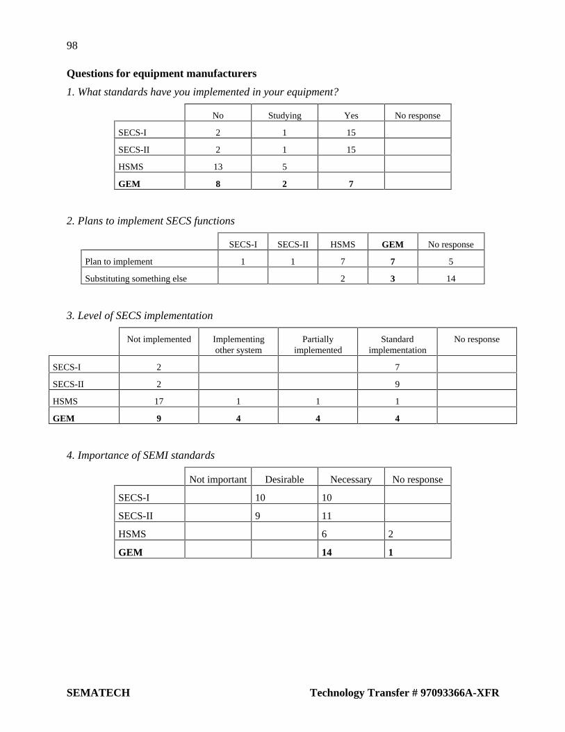
98
SEMATECH Technology Transfer # 97093366A-XFR
Questions for equipment manufacturers
1. What standards have you implemented in your equipment?
No Studying Yes No response
SECS-I 2 1 15
SECS-II 2 1 15
HSMS 13 5
GEM 8 2 7
2. Plans to implement SECS functions
SECS-I SECS-II HSMS GEM No response
Plan to implement 1 1 7 7 5
Substituting something else 2 3 14
3. Level of SECS implementation
Not implemented Implementingother system
Partiallyimplemented
Standardimplementation
No response
SECS-I 2 7
SECS-II 2 9
HSMS 17 1 1 1
GEM 9 4 4 4
4. Importance of SEMI standards
Not important Desirable Necessary No response
SECS-I 10 10
SECS-II 9 11
HSMS 6 2
GEM 14 1

99
Technology Transfer # 97093366A-XFR SEMATECH
5. Demand for SECS software packages
Develop in-house; not needed................................................. 2
Would consider, depending on price and performance...........12
Would prefer to buy from outside supplier:
SECS-I..........................................................................5
SECS-II.........................................................................5
HSMS..........................................................................15
GEM...........................................................................12
No response...............................................................................1
6. SECS software development strategies
Develop as requested by customers..........................................4
Offer own standard, do not offer major customizations...........2
Customize based on own standard.........................................14
Questions for semiconductor manufacturers
1. Have you implemented a host computer system?
No Studying Yes No response
SECS-I 3 1 13 1
SECS-II 2 14 1
HSMS 16 1
GEM 13 2 1
2. Plans to implement SECS functions
SECS-I SECS-II HSMS GEM No response
Plan to implement 1 1 5 3 8
Substituting something else 2 2 3 2 9

100
SEMATECH Technology Transfer # 97093366A-XFR
3. Implementation of SECS functions in fab’s host computer
Not implementedImplementingother system
Partiallyimplemented
Standardimplementation No response
SECS-I 2 2 11 1
SECS-II 2 3 2 9 1
HSMS 12 3 1
GEM 13 1 1 1
4. Plans to bring more equipment online
Current implementation is adequate.................................................2
Plan to expand online implementation............................................12
No response.......................................................................................0
5. Priority for putting equipment online in fab
Not important.....................................................................................0
Case-by-case......................................................................................7
Always required.................................................................................9
6. Problems bringing equipment online
Cost of developing equipment-end software...................................14
Time to get equipment-end software.................................................7
Quality of equipment-end software...................................................9
Functionality of equipment-end software..........................................6
Cost of developing host-end software...............................................8
Time to get host-end software...........................................................3
Quality of host-end software.............................................................4
Functionality of host-end software....................................................5
7. Importance of SEMI standards
Not important Desirable Necessary No response
SECS-I 2 13 1
SECS-II 2 13 1
HSMS 1 10 1 4
GEM 1 9 3 3

101
Technology Transfer # 97093366A-XFR SEMATECH
8. Demand for general-purpose SECS software packages
Develop in-house; not needed...........................................................2
Would consider, depending on price and performance...................13
Would prefer to buy from outside supplier:
SECS-I...................................................................................2
SECS-II..................................................................................3
HSMS.....................................................................................9
GEM.....................................................................................11
No response.........................................................................................2
Questions for software suppliers
1. Have you sold any products implementing SECS functions?
No Studying Yes No response
SECS-I 1 5
SECS-II 1 5
HSMS 6
GEM 4 1 1
2. Plans to offer SECS software
SECS-I SECS-II HSMS GEM No response
Plan to implement 1 1 5 3 8
Substituting something else 2 2 3 2 9
3. Type of sales
Custom-ordered.................................................................................2
General-purpose packaged software................................................13
4. Potential foreseen for general-purpose SECS software packages
None...................................................................................................1
Minor niche market............................................................................3
Will probably expand with time.........................................................2
No response........................................................................................1


SEMATECH Technology Transfer2706 Montopolis Drive
Austin, TX 78741
http://www.sematech.org