generation of wide-swath and high-resolution sar images from multichannel small spaceborne sar...
TRANSCRIPT
82 IEEE GEOSCIENCE AND REMOTE SENSING LETTERS, VOL. 2, NO. 1, JANUARY 2005
Generation of Wide-Swath and High-ResolutionSAR Images From Multichannel Small
Spaceborne SAR SystemsZhenfang Li, Hongyang Wang, Tao Su, and Zheng Bao, Senior Member, IEEE
Abstract—Future spaceborne synthetic aperture radar (SAR)systems will be required to produce high-resolution imageryover a wide area of surveillance. However, the minimum antennaarea constraint makes it a contradiction to simultaneously obtainboth unambiguous wide-area and high azimuth resolution. Toovercome this limitation, a technique has been suggested thatcombines a broad illumination source with multiple receivingchannels. Then, the coherent combination of the recorded mul-tichannel signals will allow for the unambiguous SAR mappingof a wide ground area with fine azimuth resolution. This letterfirst gives an overview of current research work carried out aboutthe generation of wide-swath and high-resolution SAR imagesfrom multichannel small spaceborne SAR systems, and then aspace-time adaptive processing (STAP) approach combined withconventional SAR imaging algorithms is presented, which couldbe of help to overcome the existing difficulties in data processing.The main idea of the approach is to use a STAP-based methodto properly overcome the aliasing affect caused by the lowerpulse repetition frequency and thereby retrieve the unambiguousazimuth wide (full) spectrum signal from the received signal.Following this operation, conventional SAR data processing toolscan be applied to fully focus the SAR images. The performance ofthe approach is also discussed in this letter. The approach has theadvantages of simplicity, robustness, and high efficiency.
Index Terms—Array signal processing, Doppler ambiguity,high resolution, spaceborne radar, space-time adaptive processing(STAP), synthetic aperture radar (SAR), wide area.
I. INTRODUCTION
ABASIC limitation for the design of spaceborne syntheticaperture radar (SAR) systems is the minimum antenna
area constraint [1], [2], which can be expressed as
(1)
where is the velocity of spaceborne platforms, is the wave-length, is the slant range, is the light speed, and is the in-cidence angle. The requirement arises because the illuminatedarea of the ground must be restricted so that the radar does notreceive ambiguous returns in range or/and Doppler. As a result,almost all of the previously and currently fielded spaceborneSAR systems have a huge antenna, such as Seasat (10.74 m2.16 m), the Japanese Earth Resources Satellite 1 (11.9 m2.4 m), the European Remote Sensing 1 and 2 tandem satell-lites (10 m 1m), Radarsat-1 (15 m 1.5 m), and Spaceborne
Manuscript received March 15, 2004; revised October 3, 2004.The authors are with Key Laboratory for Radar Signal Processing, Xidian
University, Xi’an 710071, China (e-mail: [email protected]).Digital Object Identifier 10.1109/LGRS.2004.840610
Imaging Radar C-band/X-band Synthetic Aperture Radar satel-lite (12 m 4.4 m). Unfortunately, the large antennas lead to thefailure of the conventional spaceborne SAR systems to map ofa wide area with high azimuth resolution either in the stripmapor spotlight mode.
In order to achieve both wide-area and high azimuth resolu-tion, an idea has been suggested that combines a broad illumi-nation source with multiple receiving channels. The multiple re-ceiving channels may be multiple subarrays [3]–[9] or multiplereceiving small antennas placed on separate formation-flyingmicrosatellites [10]–[12], all of which are called multichannelsmall spaceborne SAR systems in this letter. Although an indi-vidual small antenna (or subarray) does not satisfy the minimumantenna area requirement, the total receiving antenna area (i.e.,the sum of all the physical receiving aperture areas) of the multi-channel spaceborne SAR systems must do to achieve the unam-biguous SAR image by coherent combination of the data fromall receiving channels. With this precondition, echoes from mul-tiple along-track (in azimuth) spatial channels can be combinedcoherently to improve the azimuth resolution; similarly echoesfrom multiple cross-track (in elevation) spatial channels can beused to increase the swath width.
The pulse repetition frequency (PRF) is determined by thetotal receiving antenna length (i.e., the sum of all the physicalreceiving antenna lengths in azimuth) of the multichannel space-borne SAR systems. Assume the total antenna area satisfies theminimum antenna area constraint of (1). Then, the PRF mustsatisfy the following inequality:
(2)
where is the total receiving antenna length. Obviously, thePRF is much lower than that required by an individual small an-tenna ( , where is the along-track lengthof a single small antenna), thus the existence of multiple azimuth(Doppler) ambiguities for the echoes received by each channel.
This letter first gives a survey of the existing approaches to thegeneration of wide-swath and high-resolution SAR images frommultichannel small spaceborne SAR systems and then presentsa novel space-time adaptive processing (STAP) approach to re-solving the Doppler ambiguities. The main idea of the STAP ap-proach is to retrieve the unambiguous azimuth wide (full) spec-trum signal from the received data by properly overcoming thealiasing effect caused by the lower PRF through the applicationof a STAP algorithm (post-Doppler architecture). Then, conven-tional SAR data processing tools can be directly applied to fully
1545-598X/$20.00 © 2005 IEEE
LI et al.:GENERATION OF WIDE-SWATH AND HIGH-RESOLUTION SAR IMAGES 83
focus the SAR images. Using the approach, we can achieve theunambiguous wide-swath and full-resolution (theoretically, halfalong-track length of an individual small antenna in the stripmapmode) SAR images with high efficiency. To distinguish the ap-proach from the existing ones, we call it the post-Doppler STAPapproach.
The succeeding sections of this letter are arranged as follows.Section II first reviews the existing techniques for full-resolu-tion SAR image generation from the along-track multichannelsmall spaceborne SAR systems, followed by Section III, whichpresents the STAP-based approach to resolving the Dopplerambiguities and achieving the full-resolution SAR images.Finally, the performance of the proposed approach is discussedin Section IV, with our conclusions being reached in Section V.
II. SURVEY OF THE PRESENT TECHNIQUES
It is necessary to give the definition of equivalent phase centerbefore the introduction to the related techniques.
Definition: Two separate transmitting antenna and receivingantenna can be equivalent to a transmitting and receiving an-tenna that is positioned midway between the transmitting an-tenna and the receiving antenna, after compensating a constantphase (where is the distance between thetransmitting antenna and the receiving antenna). In practice, foreach range segment, only a constant phase needs to be compen-sated (i.e., can be approximated to be constant). The posi-tion of the equivalent antenna is defined as the equivalent phasecenter. This definition holds true only when the distance be-tween transmitter and receiver is small enough compared withtheir distance to the earth’s surface. It is assumed in this letterthat this definition is valid for typical multichannel spaceborneSAR system parameters.
The suppression of the range ambiguities to increase theswath width by using adaptive array techniques (multiplespatial channels in elevation) has been first investigated byGriffiths and Mancini [3] and further developed in severalfollow-on papers [5]–[10].
The basic idea of using multiple along-track spatial channels(multiple small subarrays) to achieve the high azimuth resolu-tion has been first suggested by Currie and Brown [4], whichis referred to as the displaced phase center (DPC) multibeamtechnique. Although a lower PRF (compared with that requiredby an individual small antenna) is used, which is dependent onthe total physical receiving antenna length but independent ofthe length of individual small antennas, the spatial sampling canbe increased by adding the multiple receiving channels. There-fore, if the number of the along-track small receiving antennasand their intervals are appropriately selected, no Doppler ambi-guities will exist for the whole multichannel spaceborne SARsystems; in other words, the multichannel sampling can meetthe Nyquist sampling theorem. That is the basic idea of theDPC. Under ideal conditions, the most efficient and simplestprocessing is to align the pulses from the equivalent phase cen-ters of all the receiving channels and then apply conventionalSAR imaging operations [13]–[15] to achieve the full-resolu-tion SAR images. These ideal conditions include the following.
1) The equivalent phase centers of the spatial channels mustbe uniformly distributed at the interval of ( isthe number of the along-track antennas, and denotesthe pulse repetition period). This array configuration is re-ferred to as the optimum array configuration in this letter.
2) All the receiving channels (including the beam patterns)must be identical.
3) There are no uncertainties in the platform attitude andpositions. If the ideal conditions cannot be satisfied, theDPC will not work properly.
Together with its equivalence to the DPC, the idea of azimuthambiguity cancellation by an appropriate null steering techniquehas been discussed in [5] and [6]. However, the processing ap-proach turns to be too costly, due to the fact that the ambiguitysuppression is, respectively, performed for each image point.
Further details on the azimuth ambiguity suppression tech-niques for the constellation (formation-flying microsatellites) ofsmall spaceborne SAR systems can be found in [10]–[12]. Themaximum-likelihood filter (ML) and minimum mean-squarederror (MMSE) filter (using the entire time, frequency, and spa-tial measurements) have been used to resolve the problem of therange-Doppler ambiguities and to achieve the wide-area SARimage with the constellation of small spaceborne SAR systems[10]. However, calculating the ML and MMSE filters would re-quire the inversion of an extremely large matrix, which is unreal-istic. The authors of [10] have also suggested that the SAR pro-cessing be first performed for each receiving channel and thenspatial processing be used to reject ambiguous targets for eachimage pixel. However, difficulties still exist, such as computa-tion load (due to the multiplication of SAR processing by thenumber of channels) and more spatial degrees of freedom re-quired to reject the more ambiguous targets within each imagepixel. A reconstruction algorithm based on the sampling the-orem has been investigated to recover the unambiguous Dopplerspectrum [11]. Moreover, the way to calculate the array weightsby adaptive methods has not been given in [10] and [11]. Agutteshas introduced a radically different approach to the problemof the Doppler ambiguity and nonuniform satellite spacing byusing spread spectrum waveforms [12].
III. POST-DOPPLER STAP APPROACH
A. Space-Time Spectrum
Prior to presenting the post-Doppler STAP approach, it is nec-essary to first introduce the space-time spectrum of echoes fromground stationary scene.
When a spaceborne SAR system works in the sidelookingand stripmap modes, the relationship between the Doppler fre-quency of a ground reflecting cell and its azimuth angle (orcone angle) can be formulated by
(3)
where is the Doppler term coming from the earth rota-tion, which can be assumed to be constant over a range segment(or a range bin). Suppose the azimuth mainlobe width of an in-dividual small antenna (or subarray) equals 0.015 rad, the satel-lite velocity m/s, the wavelength cm, and
84 IEEE GEOSCIENCE AND REMOTE SENSING LETTERS, VOL. 2, NO. 1, JANUARY 2005
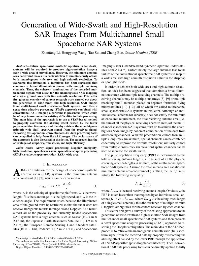
Fig. 1. Space-time spectrum of ground echoes. (a) Doppler-unambiguous.(b) Doppler-ambiguous.
(for simplicity), then the Doppler frequencies of theground scene coming from the mainlobe of a small antenna areconfined within ( 3500 Hz, 3500 Hz). The clutter Dopplerfrequency is directly proportional to , and the clutterspectrum can be shown by the thick line in the plane(also referred to as the space-time plane) of Fig. 1(a). As men-tioned above [i.e., (2)], the PRF is selected according to the totalphysical receiving antenna length, and then the PRF for the caseof five along-track small antennas should be Hz. Thelower PRF will introduce azimuth (Doppler) ambiguities for thepulses from each small receiving antenna. In this example, therewill exist five azimuth angles for the same Doppler frequency,as shown by the five thick lines in Fig. 1(b).
B. Post-Doppler STAP Approach
Before presenting the post-Doppler STAP approach, the def-inition of spectrum component is given.
Definition: The space-time spectrum lines can be dividedinto many short segments (chips) by using the azimuth fastFourier transform (FFT), each of which is defined as a spec-trum component in this letter later, such as those in the circlesmarked in Fig. 1(b).
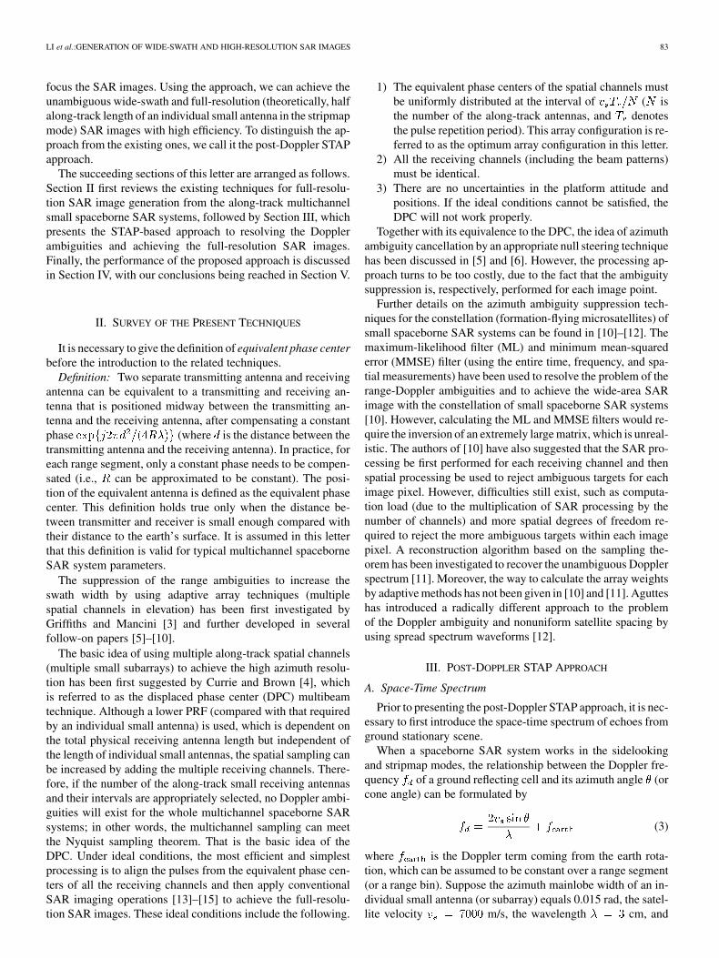
The post-Doppler STAP approach first extracts all spectrumcomponents from the space-time plane as shown in Fig. 1(b) bymeans of space-time beamforming (in practice, the space beam-forming and time beamforming are, respectively, performed).Then, these resolved spectrum components are rearranged inthe space-time plane to obtain the unambiguous full spectrum.Finally, the unambiguous full-resolution SAR image can be ob-tained from the full spectrum using conventional SAR imagingoperations. The implementation structure of the approach isshown in Fig. 2, followed by the detailed procedures.
The post-Doppler STAP approach comprises the followingfour steps.
Step 1) Temporal processing: An azimuth FFT is usedto divide the echoes received by each spatial channel intomany spectrum components (i.e., spectrum chips). Within eachDoppler bin, all the spectrum components are confined into anarrower angle space. Moreover, these spectrum componentsare completely separated from each other in the spatial domain(angle domain). In the example shown in Fig. 1(b), there arefive spectrum components within each Doppler bin.
The spectra of all ground stationary reflecting cells aresuperimposed in the space-time plane after performing theazimuth FFT, with linear phase differences corresponding totheir along-track positions. That is, all the ground stationary
Fig. 2. Implementation structure of the post-Doppler STAP approach.
reflecting cells within each spectrum component have theidentical array steer vector. As a result, the spatial processingfor each spectrum component is equivalent to processing allthe ground stationary reflecting cells within this spectrumcomponent, which is one of the reasons why the post-Dopplerprocessing is high in efficiency.
Step 2) Spatial processing: Spatial beamforming tech-niques are used to extract all spectrum components from thespace-time plane with each Doppler bin being processed,respectively. To extract a spectrum component, the array main-lobe (i.e., the array steering vector) is pointed to it, while all theother spectrum components within the corresponding Dopplerbin are nulled out; thus, the desired spectrum component isextracted. Similarly, the other spectrum components within thisDoppler bin can also be extracted. Because the coherent pro-cessing is required in the following processing steps, the phaseand amplitude information of all the spectrum componentsmust be kept unchanged in this step. The way to preserve thephase and amplitude information of all the resolved spectrumcomponents will be shown in what follows by using mathemat-ical expression.
The optimum array weight vector for extracting theth ( , is the number of spectrum components
within each Doppler bin) spectrum component from the Dopplerbin solves the following optimization:
(4)
subject to
(5)
where
(6)
(7)
(8)
(9)
and denote the vector transpose and conjugate-trans-pose operations, respectively, is the array output vector
LI et al.:GENERATION OF WIDE-SWATH AND HIGH-RESOLUTION SAR IMAGES 85
from the Doppler bin , is the covariance matrix cor-responding to the array output from the Doppler bin ,denotes the statistical averaging, is the array steer vectorof the th spectrum component to be extracted, is theazimuth angle of the th spectrum component, denotes theequivalent phase center of the th spatial channel, and
. In practice, the statistical covariance matrix of (8)can be estimated from the sample covariance matrix, and thesamples can be easily obtained from range bins (i.e., range sam-ples), i.e., the sample covariance matrix can be calculatedby
(10)
where is the number of independent and identically dis-tributed samples used to estimate the covariance matrix, and
denotes the array output vector from the Doppler binand range bin . Reed et al. have shown that
is a rule for a 3-dB loss due to estimation [16].Solving the optimization of (4) subject to (5), the approxi-
mately optimum adaptive weight vector can be given by
(11)
One major advantage of the array weight obtained by (11)is that it can preserve the phase and amplitude information ofeach extracted spectrum component. That is, it does not changethe phase and amplitude relationships among all the spectrumcomponents.
Step 3) Rearranging spectrum components: After all thespectrum components are extracted, they are then rearranged toachieve the unambiguous full spectrum as shown in Fig. 1(a).Moreover, the PRF must also be increased by five. The full-spectrum signal can then be further processed by using SARimaging operations.
Step 4) Conventional SAR processing: The unambiguousfull-spectrum signal obtained in step 3) can then be processedby using conventional SAR imaging operations [13]–[15] suchas range migration compensation, range compression, azimuthcompression, etc. Finally, the wide swath and high-resolution(due to the small antennas) SAR images of ground scenes canbe obtained.
IV. PERFORMANCE INVESTIGATION
In this section, we investigate two key performance measuresof the post-Doppler STAP approach: Doppler ambiguity sup-pression and SNR loss.
Suppose all the subarrays (or small antennas) are distributedin the along-track direction within the range of . Othermain simulation parameters of the multichannel small space-borne SAR systems are listed in Table I. It is also assumedthat the spaceborne SAR systems operate in the sidelooking andstripmap mode.
In what follows, several examples are first given to demon-strate the effect of different array configurations on the Dopplerambiguity suppression. Assume that the number of subarraysis five, that no noise exists, and that the three array configura-tions are also listed in Table I. The results of the Doppler am-
TABLE IMAIN SIMULATION PARAMETERS OF THE MULTICHANNEL
SMALL SPACEBORNE SAR SYSTEMS
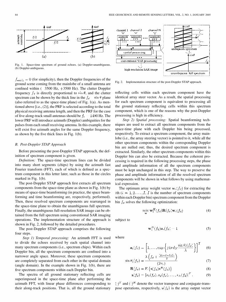
Fig. 3. Full-resolution SAR images of a single scatterer (a) withoutsuppressing Doppler ambiguities, with Doppler ambiguities suppressed(b) by array configuration 1, (c) by array configuration 2, and (d) by arrayconfiguration 3.
biguity suppression for the three array configurations throughthe use of the post-Doppler STAP approach are shown in Fig. 3.Fig. 3(a) is the one-dimensional full-resolution SAR image of asingle stationary scatterer without suppressing the Doppler am-biguities. The existence of the five Doppler ambiguities makeseach target corresponding to eight ambiguous targets. Fig. 3(b)is the SAR image with the Doppler ambiguities suppressed bythe array configuration 1. Because the array elements (equiva-lent phase centers) are well distributed in the range of ,the array configuration 1 is very suitable for the Doppler ambi-guity suppression. Fig. 3(c) and (d) shows the SAR images withthe Doppler ambiguities suppressed by the array configuration 2and array configuration 3, respectively. From Fig. 3(c) and (d),we can see that the good results can still be achieved even if thearray elements are so crowded within an array length much lessthan .
However, it should be noted that the results shown in Fig. 3are obtained in the case of no noise. In fact, the SNR may not behigh enough, because of the low transmitted power, small trans-mitting antenna area, etc. Furthermore, for the nonoptimal arrayconfigurations, the spatial processing can also result in SNR lossrelative to the optimum array configuration dB .To quantitatively assess the SNR loss, we compute the SNRloss for different array configurations and different numbers( , and ) of array elements. Assume the array el-ements are distributed in the range of with a uniformrandom distribution, and the input SNR (i.e., the SNR prior to
86 IEEE GEOSCIENCE AND REMOTE SENSING LETTERS, VOL. 2, NO. 1, JANUARY 2005
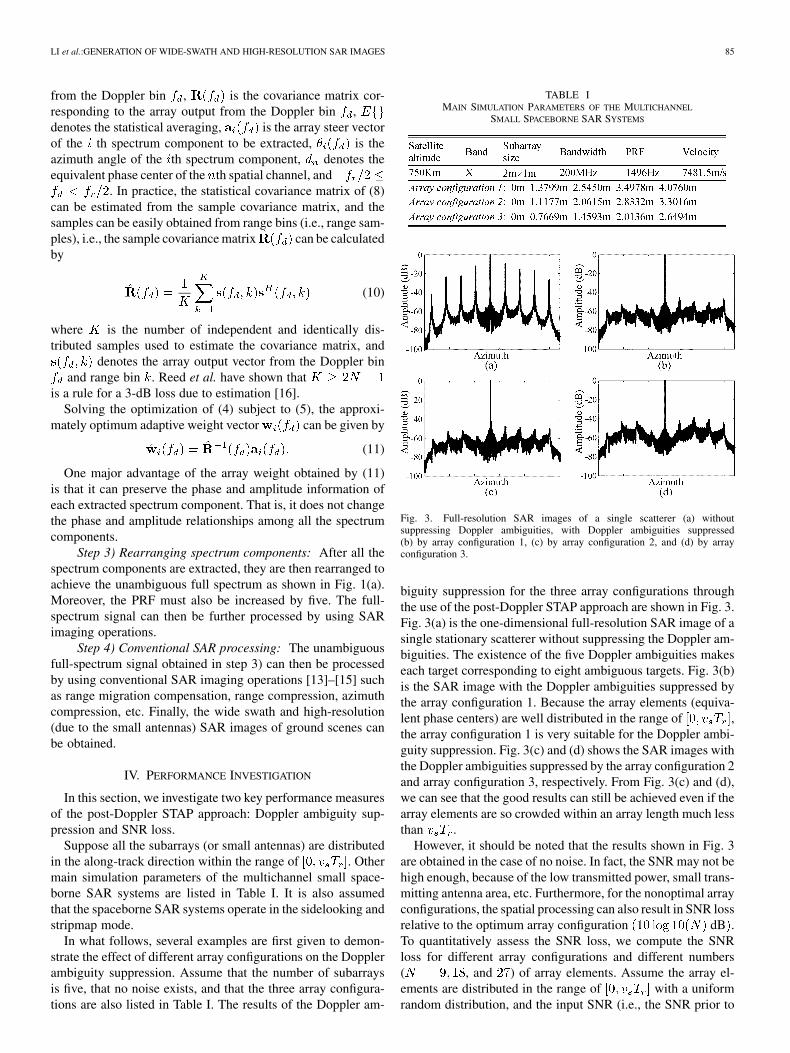
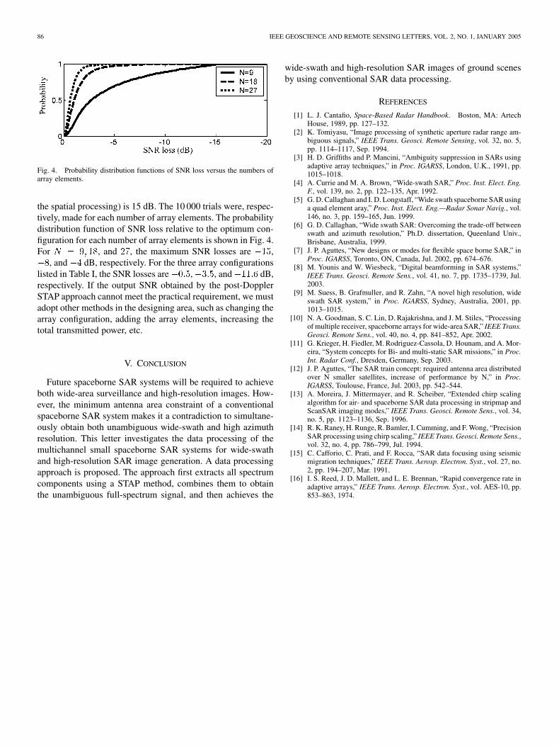
Fig. 4. Probability distribution functions of SNR loss versus the numbers ofarray elements.
the spatial processing) is 15 dB. The 10 000 trials were, respec-tively, made for each number of array elements. The probabilitydistribution function of SNR loss relative to the optimum con-figuration for each number of array elements is shown in Fig. 4.For , and , the maximum SNR losses are ,
, and dB, respectively. For the three array configurationslisted in Table I, the SNR losses are , , and dB,respectively. If the output SNR obtained by the post-DopplerSTAP approach cannot meet the practical requirement, we mustadopt other methods in the designing area, such as changing thearray configuration, adding the array elements, increasing thetotal transmitted power, etc.
V. CONCLUSION
Future spaceborne SAR systems will be required to achieveboth wide-area surveillance and high-resolution images. How-ever, the minimum antenna area constraint of a conventionalspaceborne SAR system makes it a contradiction to simultane-ously obtain both unambiguous wide-swath and high azimuthresolution. This letter investigates the data processing of themultichannel small spaceborne SAR systems for wide-swathand high-resolution SAR image generation. A data processingapproach is proposed. The approach first extracts all spectrumcomponents using a STAP method, combines them to obtainthe unambiguous full-spectrum signal, and then achieves the
wide-swath and high-resolution SAR images of ground scenesby using conventional SAR data processing.
REFERENCES
[1] L. J. Cantafio, Space-Based Radar Handbook. Boston, MA: ArtechHouse, 1989, pp. 127–132.
[2] K. Tomiyasu, “Image processing of synthetic aperture radar range am-biguous signals,” IEEE Trans. Geosci. Remote Sensing, vol. 32, no. 5,pp. 1114–1117, Sep. 1994.
[3] H. D. Griffiths and P. Mancini, “Ambiguity suppression in SARs usingadaptive array techniques,” in Proc. IGARSS, London, U.K., 1991, pp.1015–1018.
[4] A. Currie and M. A. Brown, “Wide-swath SAR,” Proc. Inst. Elect. Eng.F., vol. 139, no. 2, pp. 122–135, Apr. 1992.
[5] G. D. Callaghan and I. D. Longstaff, “Wide swath spaceborne SAR usinga quad element aray,” Proc. Inst. Elect. Eng.—Radar Sonar Navig., vol.146, no. 3, pp. 159–165, Jun. 1999.
[6] G. D. Callaghan, “Wide swath SAR: Overcoming the trade-off betweenswath and azimuth resolution,” Ph.D. dissertation, Queenland Univ.,Brisbane, Australia, 1999.
[7] J. P. Aguttes, “New designs or modes for flexible space borne SAR,” inProc. IGARSS, Toronto, ON, Canada, Jul. 2002, pp. 674–676.
[8] M. Younis and W. Wiesbeck, “Digital beamforming in SAR systems,”IEEE Trans. Geosci. Remote Sens., vol. 41, no. 7, pp. 1735–1739, Jul.2003.
[9] M. Suess, B. Grafmuller, and R. Zahn, “A novel high resolution, wideswath SAR system,” in Proc. IGARSS, Sydney, Australia, 2001, pp.1013–1015.
[10] N. A. Goodman, S. C. Lin, D. Rajakrishna, and J. M. Stiles, “Processingof multiple receiver, spaceborne arrays for wide-area SAR,” IEEE Trans.Geosci. Remote Sens., vol. 40, no. 4, pp. 841–852, Apr. 2002.
[11] G. Krieger, H. Fiedler, M. Rodriguez-Cassola, D. Hounam, and A. Mor-eira, “System concepts for Bi- and multi-static SAR missions,” in Proc.Int. Radar Conf., Dresden, Germany, Sep. 2003.
[12] J. P. Aguttes, “The SAR train concept: required antenna area distributedover N smaller satellites, increase of performance by N,” in Proc.IGARSS, Toulouse, France, Jul. 2003, pp. 542–544.
[13] A. Moreira, J. Mittermayer, and R. Scheiber, “Extended chirp scalingalgorithm for air- and spaceborne SAR data processing in stripmap andScanSAR imaging modes,” IEEE Trans. Geosci. Remote Sens., vol. 34,no. 5, pp. 1123–1136, Sep. 1996.
[14] R. K. Raney, H. Runge, R. Bamler, I. Cumming, and F. Wong, “PrecisionSAR processing using chirp scaling,” IEEE Trans. Geosci. Remote Sens.,vol. 32, no. 4, pp. 786–799, Jul. 1994.
[15] C. Cafforio, C. Prati, and F. Rocca, “SAR data focusing using seismicmigration techniques,” IEEE Trans. Aerosp. Electron. Syst., vol. 27, no.2, pp. 194–207, Mar. 1991.
[16] I. S. Reed, J. D. Mallett, and L. E. Brennan, “Rapid convergence rate inadaptive arrays,” IEEE Trans. Aerosp. Electron. Syst., vol. AES-10, pp.853–863, 1974.