general view - etneterastest1.etnetera.cz/ad/current/content/data_files/technika_pohonu/... ·...
TRANSCRIPT
Function diagram87654321
- 010 -General view
SINAMICS G15012.08.08
A5E00197559A AG
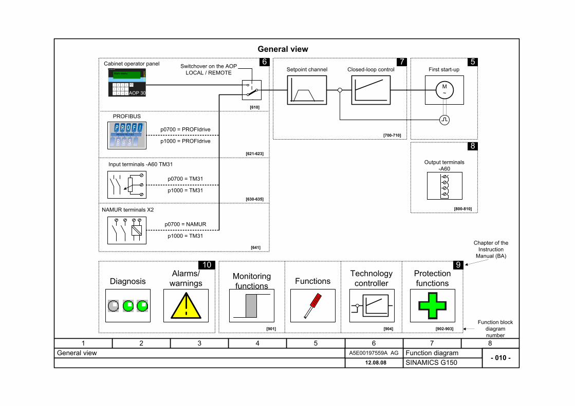
General view
Setpoint channel Closed-loop controlMain menu
SIN
AMIC
S
SIEMENS
7
1
4
8
5
2 3
6
9 0
.
+/- AOP 30
Local Remot
e M ~
Diagnosis FunctionsProtection functions
Monitoring functions
Alarms/warnings
Cabinet operator panel
Input terminals -A60 TM31
PROFIBUS
Output terminals -A60
6 7 5
8
10 9
First start-up
Chapter of the Instruction
Manual (BA)
Function block diagram number
[610]
[621-623]
[630-635]
[700-710]
[800-810]
[901] [902-903]
p0700 = PROFIdrive
p0700 = TM31
[641]
NAMUR terminals X2
p0700 = NAMUR
Switchover on the AOP LOCAL / REMOTE
p1000 = PROFIdrive
p1000 = TM31
p1000 = TM31
Technology controller
[904]
Function diagram87654321
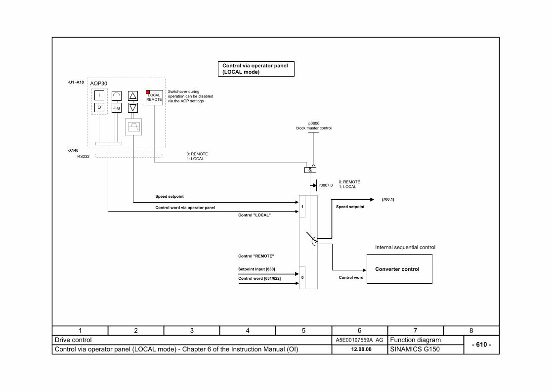
- 610 -Drive control
SINAMICS G15012.08.08Control via operator panel (LOCAL mode) - Chapter 6 of the Instruction Manual (OI)A5E00197559A AG
Jog
AOP30
LOCAL REMOTE
I
O
RS232
1
0
&
0: REMOTE 1: LOCAL
Internal sequential control
Converter control
Speed setpoint
Control word
Control via operator panel (LOCAL mode)
Control "LOCAL"
Control "REMOTE"
Speed setpoint
Control word via operator panel
[700.1]
Setpoint input [630]
Control word [631/622]
-U1 -A10
0: REMOTE 1: LOCALr0807.0
Switchover during operation can be disabled via the AOP settings
p0806 block master control
-X140
Function diagram87654321
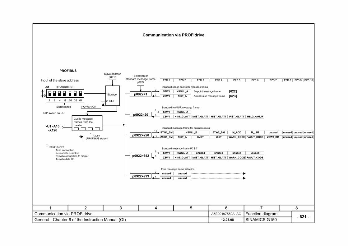
- 621 -Communication via PROFIdrive
SINAMICS G15012.08.08General - Chapter 6 of the Instruction Manual (OI)A5E00197559A AG
Communication via PROFIdrive
PROFIBUS
NSOLL_A
Input of the slave address
DIP switch on CU
DP ADDRESS
10
1 2 4 8 16 32 64
POWER ON
Storage
SET
Significance
-S1
Cyclic message frames from the master
Setpoint message frame
Actual value message frame
2
-U1 -A10-X126
r2054 (PROFIBUS status)
1)
1)r2054: 0=OFF 1=no connection 2=baudrate detected 3=cyclic connection to master 4=cyclic data OK
6
[622]
p0922=20
Standard speed controller message frame
Standard NAMUR message frame
Standard message frame PCS 7
Free message frame selection
[623]
Selection of standard message frame
p0922
Slave address p0918
NIST_GLATT IAIST_GLATT MIST_GLATT PIST_GLATT MELD_NAMUR
NSOLL_A unused unused
NIST_GLATT IAIST_GLATT MIST_GLATT WARN_CODE FAULT_CODE
unused unused
NSOLL_A
NIST_A
Standard message frame for business metal
NSOLL_B STW2_BM
NIST_A IAIST MIST WARN_CODE FAULT_CODE
M_ADD M_LIM unused unused unused unused
ZSW2_BM unused unusedunused
STW1_BM
ZSW1_BM
STW1
ZSW1
STW1
ZSW1
2
2p0922=1
10
10p0922=220
6
6p0922=352STW1
ZSW1
unusedx
xp0922=999 unused
unused
unused
PZD 1 PZD 2 PZD 3 PZD 4 PZD 5 PZD 6 PZD 7 PZD 8 PZD 9 PZD 10
Function diagram87654321
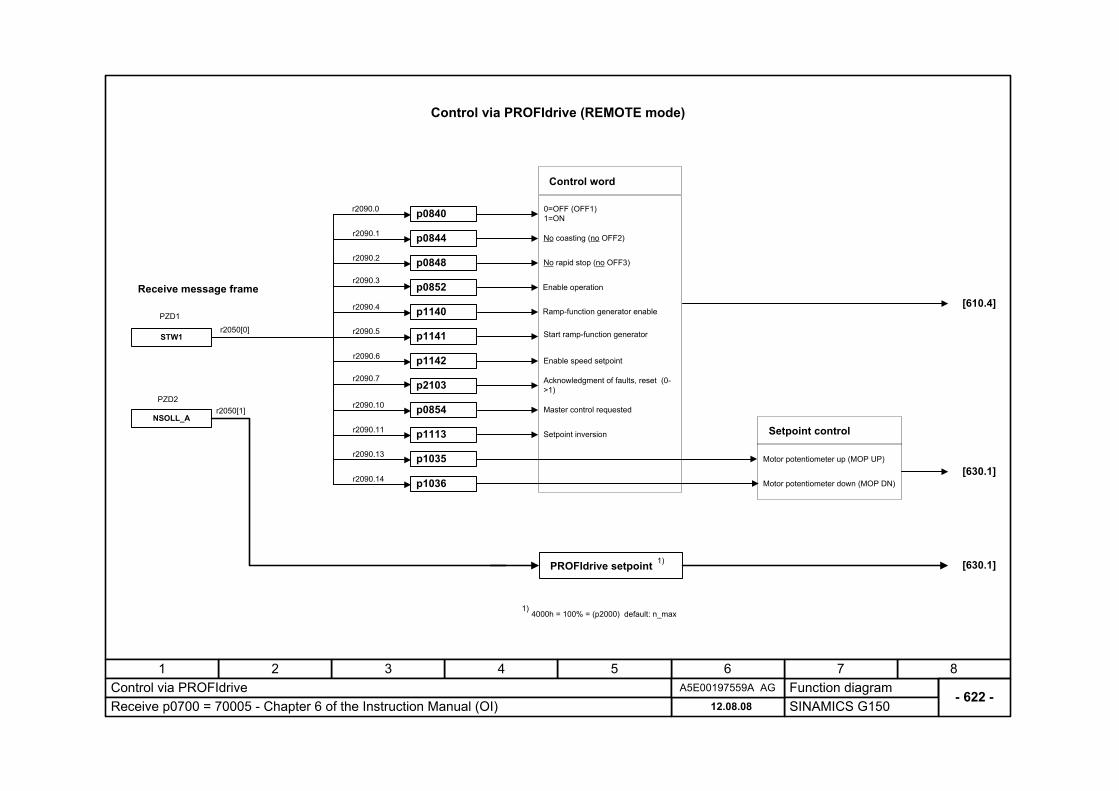
- 622 -Control via PROFIdrive
SINAMICS G15012.08.08Receive p0700 = 70005 - Chapter 6 of the Instruction Manual (OI)A5E00197559A AG
Control via PROFIdrive (REMOTE mode)
No coasting (no OFF2)
No rapid stop (no OFF3)
Enable operation
Ramp-function generator enable
Start ramp-function generator
Enable speed setpoint
Master control requested
Motor potentiometer down (MOP DN)
Motor potentiometer up (MOP UP)
1)4000h = 100% = (p2000) default: n_max
[630.1]
[630.1]PROFIdrive setpoint 1)
STW1
Receive message frame
p1142
r2050[0]
p0844
p0848
p0852
p1140
p1141
p0840
p1113
p2103
p0854
Control word
0=OFF (OFF1) 1=ON
Acknowledgment of faults, reset (0->1)
p1035
r2090.0
r2090.1
r2090.2
r2090.3
r2090.4
r2090.5
r2090.6
r2090.7
r2090.10
r2090.11
r2090.13
Setpoint control
[610.4]
r2050[1]
PZD1
PZD2
NSOLL_A
p1036r2090.14
Setpoint inversion
Function diagram87654321
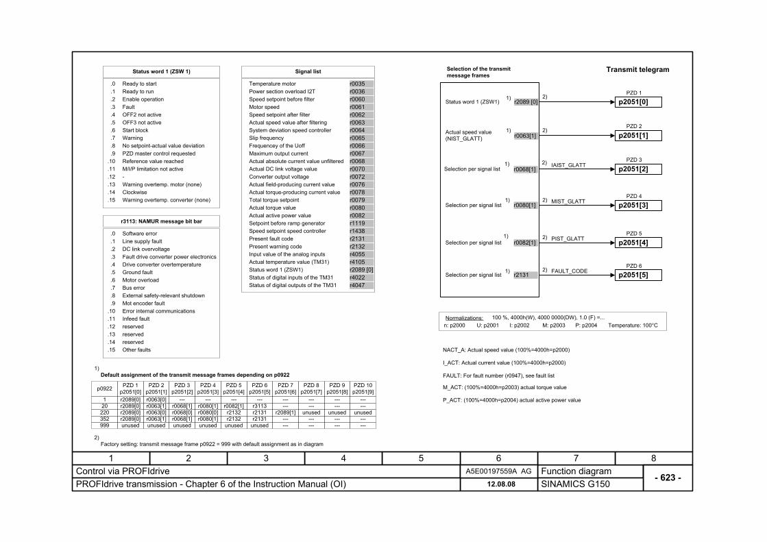
- 623 -Control via PROFIdrive
SINAMICS G15012.08.08PROFIdrive transmission - Chapter 6 of the Instruction Manual (OI)A5E00197559A AG
n: p2000Normalizations:
U: p2001 I: p2002 M: p2003 P: p2004 Temperature: 100°C100 %, 4000h(W), 4000 0000(DW), 1.0 (F) =...
Selection of the transmit message frames
NACT_A: Actual speed value (100%=4000h=p2000)
I_ACT: Actual current value (100%=4000h=p2000)
FAULT: For fault number (r0947), see fault list
M_ACT: (100%=4000h=p2003) actual torque value
Ready to start
Warning
.0
.6
.12
.13
.1
.2
.3
.4
.5
.7
.8
.9.10.11
.14
Ready to runEnable operationFaultOFF2 not activeOFF3 not activeStart block
No setpoint-actual value deviationPZD master control requestedReference value reachedM/I/P limitation not active
Warning overtemp. motor (none)Clockwise
-
.15 Warning overtemp. converter (none)
Status word 1 (ZSW 1)
P_ACT: (100%=4000h=p2004) actual active power value
Temperature motor
Motor speed
Power section overload I2TSpeed setpoint before filter
Signal list
r0036r0060r0061
r0035
Speed setpoint after filterActual speed value after filteringSystem deviation speed controllerSlip frequency
r0062r0063r0064r0065
Frequencey of the Uoff
Actual DC link voltage value
Maximum output currentActual absolute current value unfiltered
r0067r0068r0070
r0066
Converter output voltage r0072Actual field-producing current value
Actual torque value
Actual torque-producing current valueTotal torque setpoint
r0078r0079r0080
r0076
Actual active power valueSetpoint before ramp generatorSpeed setpoint speed controllerPresent fault code
r0082r1119r1438r2131
Present warning code
Status word 1 (ZSW1)
Input value of the analog inputsActual temperature value (TM31)
r4055r4105r2089 [0]
r2132
Status of digital inputs of the TM31 r4022Status of digital outputs of the TM31 r4047
Default assignment of the transmit message frames depending on p09221)
p2051[0]PZD 1
p2051[1]PZD 2
p2051[2]PZD 3
p2051[3]PZD 4
p2051[4]PZD 5
p2051[5]PZD 6
Status word 1 (ZSW1) r2089 [0]
Actual speed value (NIST_GLATT) r0063[1]
Selection per signal list r0068[1]
Selection per signal list r0080[1]
Selection per signal list r0082[1]
Selection per signal list r2131
1)
1)
1)
1)
1)
1)
Transmit telegram
2) IAIST_GLATT
2) MIST_GLATT
2) PIST_GLATT
2) FAULT_CODE
2)
2)
Factory setting: transmit message frame p0922 = 999 with default assignment as in diagram2)
1
p0922
20220352999
r2089[0]
PZD 1p2051[0]
unused
r2089[0]
unused
r2089[0]r2089[0]
r0063[0]
PZD 2p2051[1]
r0063[1]r0063[0]r0063[1]
unused
---
PZD 3p2051[2]
r0068[1]r0068[0]r0068[1]
unused
---
PZD 4p2051[3]
r0080[1]r0080[0]r0080[1]
unused
---
PZD 5p2051[4]
r0082[1]r2132r2132
unused
---
PZD 6p2051[5]
r3113r2131r2131
---
---
PZD 7p2051[6]
---r2089[1]
------
---
PZD 8p2051[7]
---unused
------
---
PZD 9p2051[8]
---unused
------
---
PZD 10p2051[9]
---unused
---
Software error
Bus error
.0
.6
.12
.13
.1
.2
.3
.4
.5
.7
.8
.9.10.11
.14
Line supply faultDC link overvoltageFault drive converter power electronicsDrive converter overtemperatureGround faultMotor overload
External safety-relevant shutdownMot encoder faultError internal communicationsInfeed fault
reservedreserved
reserved
.15 Other faults
r3113: NAMUR message bit bar
Function diagram87654321
- 630 -Speed setpoint selection
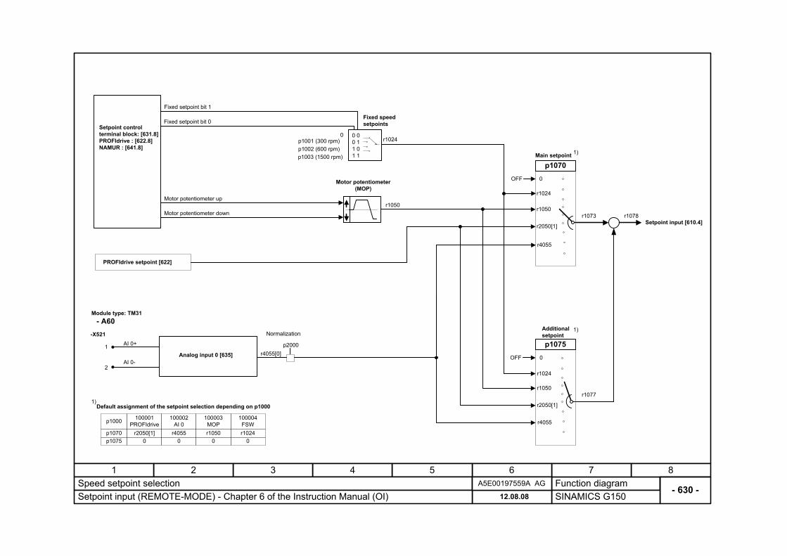
SINAMICS G15012.08.08Setpoint input (REMOTE-MODE) - Chapter 6 of the Instruction Manual (OI)A5E00197559A AG
Analog input 0 [635] r4055[0]
- A60Module type: TM31
Motor potentiometer (MOP)
p1003 (1500 rpm) p1002 (600 rpm)p1001 (300 rpm)
Fixed speed setpoints
0 0 0 0 1 1 0 1 1
p1070Main setpoint
p2000
r1050
Normalization
r1024
OFF
r4055
r1024
r1050
-X521AI 0+
AI 0-
1
2
r1078
r2050[1]
Motor potentiometer up
Motor potentiometer down
Fixed setpoint bit 1
Fixed setpoint bit 0Setpoint control terminal block: [631.8] PROFIdrive : [622.8] NAMUR : [641.8]
PROFIdrive setpoint [622]
0
p1075
Additional setpoint
r4055
r1024
r1050
r2050[1]
0OFF
r1073
r1077
Setpoint input [610.4]
Default assignment of the setpoint selection depending on p10001)
1)
1)
p1000
p1070p1075
100001PROFIdrive
r2050[1]0
100002AI 0
r40550
100003MOPr1050
0
100004FSWr1024
0
Function diagram87654321
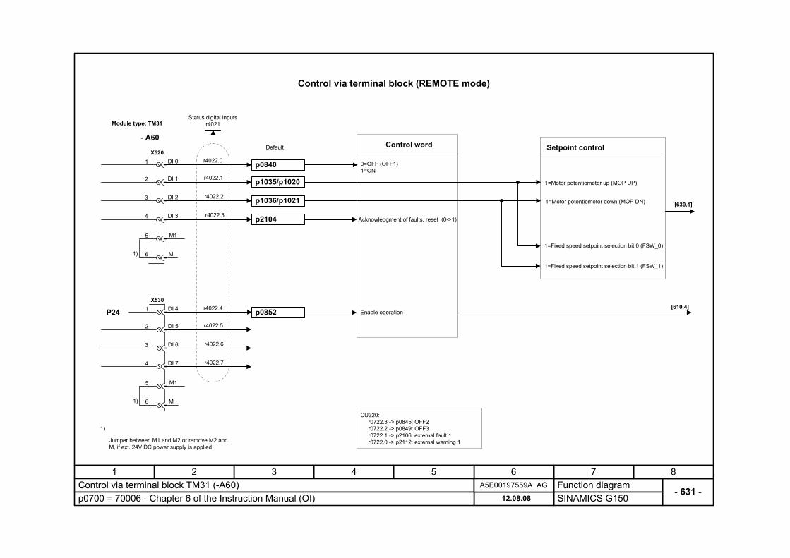
- 631 -Control via terminal block TM31 (-A60)
SINAMICS G15012.08.08p0700 = 70006 - Chapter 6 of the Instruction Manual (OI)A5E00197559A AG
DI 0
4
3
2
1
DI 1
DI 3
DI 2
5 M1
6 M
X520
1)
1)
Jumper between M1 and M2 or remove M2 and M, if ext. 24V DC power supply is applied
p0840
p1035/p1020
Control word
r4022.0
r4022.1
1=Fixed speed setpoint selection bit 0 (FSW_0)
0=OFF (OFF1) 1=ON
Acknowledgment of faults, reset (0->1)
1=Motor potentiometer up (MOP UP)
1=Fixed speed setpoint selection bit 1 (FSW_1)
Enable operation
Setpoint control
[630.1]
r4022.4
r4022.5
r4022.6
r4022.7
p1036/p1021
p2104
DI 4
4
3
2
1
DI 5
DI 7
DI 6
5 M1
6 M
X530
1)
r4022.2
r4022.3
1=Motor potentiometer down (MOP DN)
P24
Status digital inputs r4021
[610.4]
Default
Control via terminal block (REMOTE mode)
- A60
Module type: TM31
CU320: r0722.3 -> p0845: OFF2 r0722.2 -> p0849: OFF3 r0722.1 -> p2106: external fault 1 r0722.0 -> p2112: external warning 1
p0852
Function diagram87654321
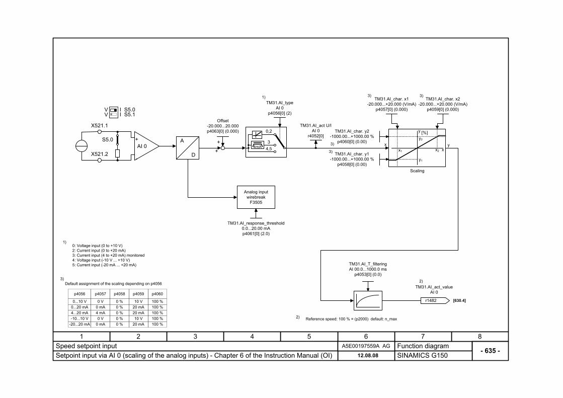
- 635 -Speed setpoint input
SINAMICS G15012.08.08Setpoint input via AI 0 (scaling of the analog inputs) - Chapter 6 of the Instruction Manual (OI)A5E00197559A AG
TM31.AI_T_filtering AI 00.0...1000.0 ms
p4053[0] (0.0)
A
D
TM31.AI_type AI 0
p4056[0] (2)
S5.0 +
-
AI 0X521.2
Analog input wirebreak
F3505
TM31.AI_act U/I AI 0
r4052[0]
X521.1
S5.0S5.1
VII
V
Scaling
TM31.AI_char. x1 -20.000...+20.000 (V/mA)
p4057[0] (0.000)
TM31.AI_char. x2 -20.000...+20.000 (V/mA)
p4059[0] (0.000)
TM31.AI_char. y2 -1000.00...+1000.00 %
p4060[0] (0.00) x yx1
y2
x2
y1
y
x
[%]
TM31.AI_char. y1 -1000.00...+1000.00 %
p4058[0] (0.00)
[630.4]
2)
2) Reference speed: 100 % = (p2000) default: n_max
1)0: Voltage input (0 to +10 V) 2: Current input (0 to +20 mA) 3: Current input (4 to +20 mA) monitored 4: Voltage input (-10 V ... +10 V) 5: Current input (-20 mA ... +20 mA)
1)
Offset -20.000...20.000 p4063[0] (0.000)
+
+ 4,53
0,2
4mA
TM31.AI_response_threshold0.0...20.00 mA p4061[0] (2.0)
r1482
TM31.AI_act_value AI 0
Default assignment of the scaling depending on p40563)
3)
3)
3)
3)
p4056
0...10 V0...20 mA4...20 mA-10...10 V
-20...20 mA
p4057
0 V0 mA4 mA0 V
0 mA
p4058
0 %0 %0 %0 %0 %
p4059
10 V20 mA20 mA10 V
20 mA
p4060
100 %100 %100 %100 %100 %
Function diagram87654321
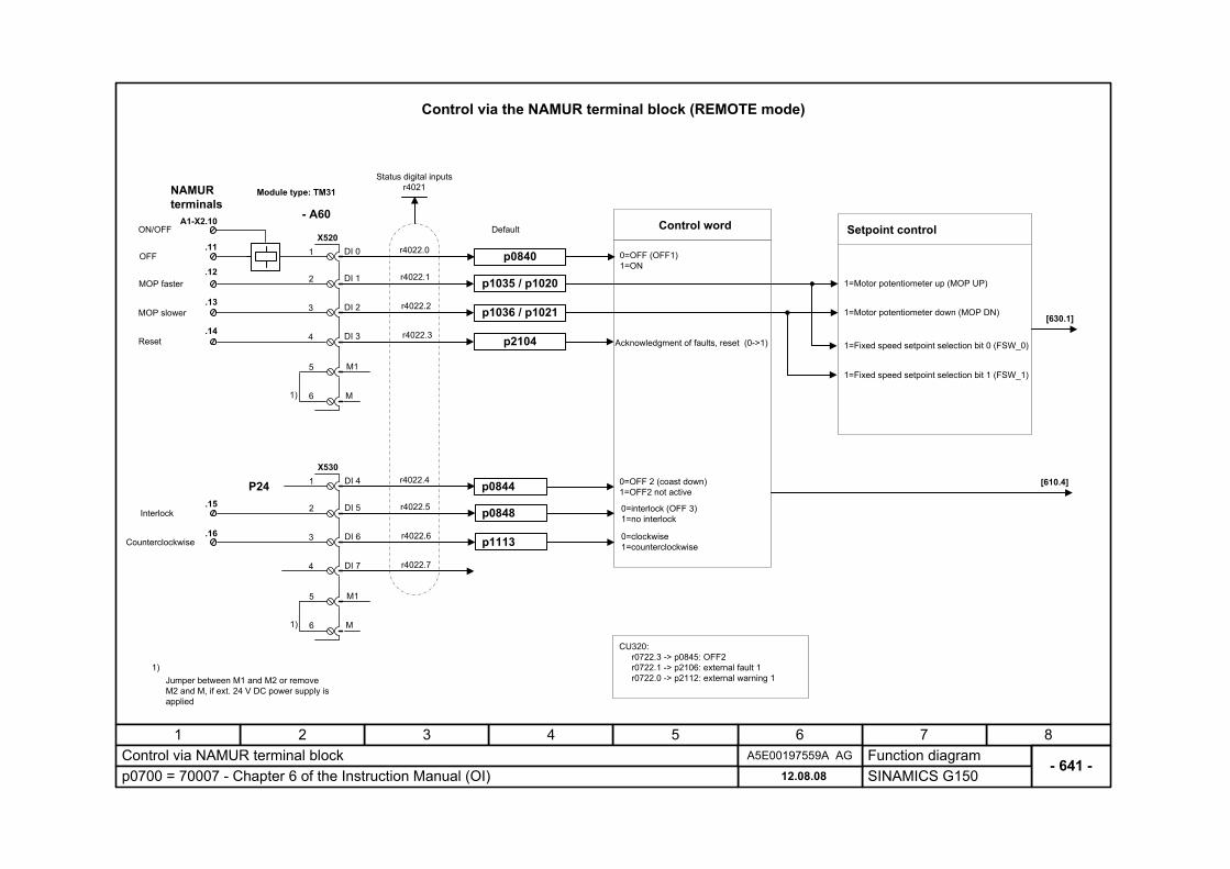
- 641 -Control via NAMUR terminal block
SINAMICS G15012.08.08p0700 = 70007 - Chapter 6 of the Instruction Manual (OI)A5E00197559A AG
DI 0
4
3
2
1
DI 1
DI 3
DI 2
5 M1
6 M
X520
1)
1)Jumper between M1 and M2 or remove M2 and M, if ext. 24 V DC power supply is applied
p0840
Control word
r4022.0
r4022.1
0=OFF (OFF1) 1=ON
Acknowledgment of faults, reset (0->1)
1=Motor potentiometer up (MOP UP)
0=OFF 2 (coast down) 1=OFF2 not active
Setpoint control
[630.1]
r4022.4
r4022.5
r4022.6
r4022.7
DI 4
4
3
2
1
DI 5
DI 7
DI 6
5 M1
6 M
X530
1)
p0844
r4022.2
r4022.3
1=Motor potentiometer down (MOP DN)
P24
Status digital inputs r4021
[610.4]
Default
Control via the NAMUR terminal block (REMOTE mode)
- A60
Module type: TM31
p0848
p1113
0=interlock (OFF 3) 1=no interlock
0=clockwise 1=counterclockwise
A1-X2.10
.12
.13
.14
.15
.16
.11
ON/OFF
OFF
MOP faster
MOP slower
Reset
Interlock
Counterclockwise
NAMUR terminals
p1035 / p1020
p1036 / p1021
p2104 1=Fixed speed setpoint selection bit 0 (FSW_0)
1=Fixed speed setpoint selection bit 1 (FSW_1)
CU320: r0722.3 -> p0845: OFF2 r0722.1 -> p2106: external fault 1 r0722.0 -> p2112: external warning 1
Function diagram87654321
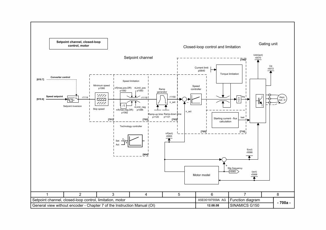
- 700a -Setpoint channel, closed-loop control, limitation, motor
SINAMICS G15012.08.08General view without encoder - Chapter 7 of the Instruction Manual (OI)A5E00197559A AG
Ramp generator
Minimum speed p1080
Speed limitation
r1119
n/f(act) r0063
Ramp-up time p1120
Ramp-down time p1121
–x y
Asyc. mot. 3~
Torque limitation
+
r0065Slip frequency
Motor model
Closed-loop control and limitationGating unit
Current limitp0640
i(act) r0068
Ua r0072
Udcl(act) r0070
f(out) r0066
Setpoint channel
Isq-1
r1150r1114Speed setpoint
n/f(max,pos.DR) p1082
nLimit_pos p1083
nLimit_neg p1086n/f(max,neg.DR)
p1082
Setpoint channel, closed-loop control, motor
Starting current - flux calculation
Iset
[710]
[610.6]
Skip speed
[701]
n_act
n_set
Converter control[610.7]
Setpoint inversion
Speed controller
[702] [703]
[705]
[706]
-1
[904]
Technology controller
SetAct
++
Function diagram87654321
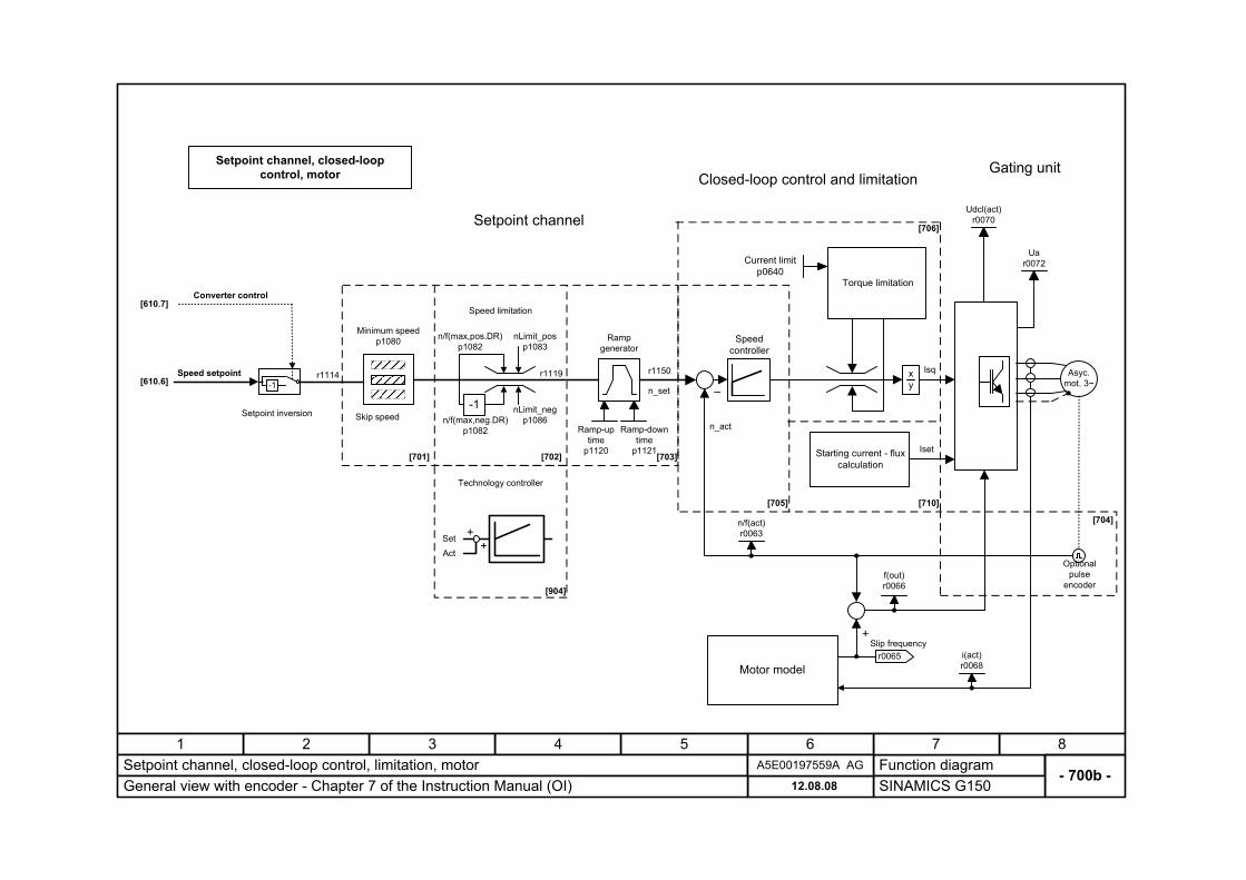
- 700b -Setpoint channel, closed-loop control, limitation, motor
SINAMICS G15012.08.08General view with encoder - Chapter 7 of the Instruction Manual (OI)A5E00197559A AG
Ramp generator
Minimum speed p1080
Speed limitation
r1119
n/f(act) r0063
Ramp-uptime
p1120
Ramp-downtime
p1121
–x y
Asyc. mot. 3~
Torque limitation
+
r0065Slip frequency
Motor model
Closed-loop control and limitationGating unit
Current limitp0640
i(act) r0068
Ua r0072
Udcl(act) r0070
f(out) r0066
Setpoint channel
Isq
-1r1150r1114Speed setpoint
n/f(max,pos.DR) p1082
nLimit_pos p1083
nLimit_neg p1086n/f(max,neg.DR)
p1082
Setpoint channel, closed-loop control, motor
Starting current - flux calculation
Iset
[710]
[610.6]
Skip speed
[701]
n_act
n_set
Converter control[610.7]
Setpoint inversion
Speed controller
[702] [703]
[705]
[706]
Optional pulse
encoder
[704]
-1
[904]
Technology controller
SetAct
++
Function diagram87654321
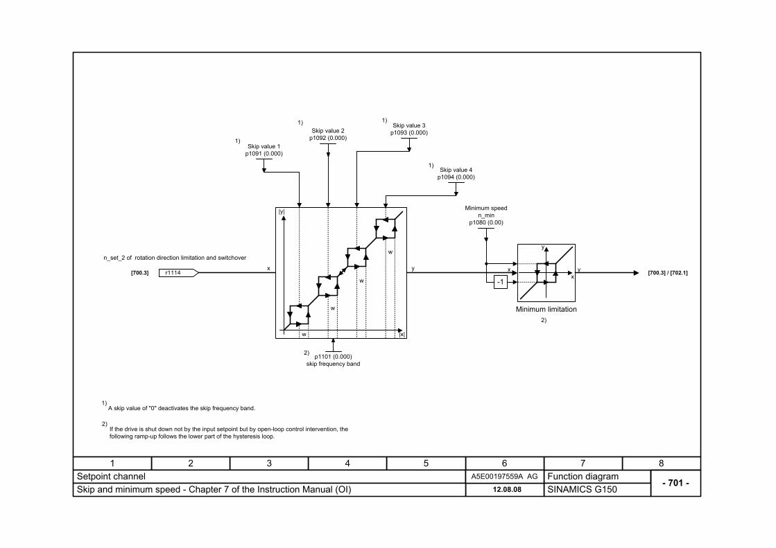
- 701 -Setpoint channel
SINAMICS G15012.08.08Skip and minimum speed - Chapter 7 of the Instruction Manual (OI)A5E00197559A AG
Skip value 2 p1092 (0.000)
Skip value 3 p1093 (0.000)
Skip value 1 p1091 (0.000)
Skip value 4 p1094 (0.000)
p1101 (0.000) skip frequency band
Minimum speed n_min
p1080 (0.00)
-1
xy r1114
n_set_2 of rotation direction limitation and switchover
1)
1)
1)
1)
|x|
|y|
w
w
w
w
x
y
2)
2)
Minimum limitation
x y[700.3] [700.3] / [702.1]
A skip value of "0" deactivates the skip frequency band. 1)
2)If the drive is shut down not by the input setpoint but by open-loop control intervention, the following ramp-up follows the lower part of the hysteresis loop.
Function diagram87654321
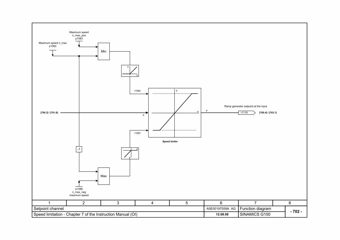
- 702 -Setpoint channel
SINAMICS G15012.08.08Speed limitation - Chapter 7 of the Instruction Manual (OI)A5E00197559A AG
y
x[700.3] / [701.8] [700.4] / [703.1]x
y
-1
Maximum speed n_max_pos
p1083
Maximum speed n_max p1082
p1086 n_max_neg
maximum speed
r1084
r1087
r1119
Ramp generator setpoint at the input
x
y
x
y
Min
Max
Speed limiter
Function diagram87654321
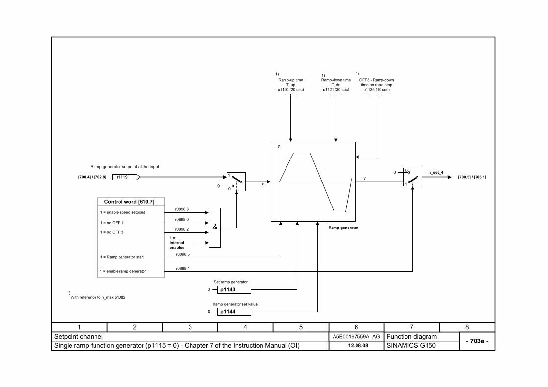
- 703a -Setpoint channel
SINAMICS G15012.08.08Single ramp-function generator (p1115 = 0) - Chapter 7 of the Instruction Manual (OI)A5E00197559A AG
yx
[700.4] / [702.8] [700.5] / [705.1]
r0898.5
r1119
Ramp generator setpoint at the input
Ramp-up time T_up
p1120 (20 sec)
Ramp-down time T_dn
p1121 (30 sec)
OFF3 - Ramp-down time on rapid stop
p1135 (10 sec)
1) 1) 1)
1 = enable ramp generator
1 = Ramp generator start
1 = enable speed setpoint
Control word [610.7]
r0898.4
1
00 n_set_4
&1 = no OFF 1
1 = no OFF 31 = internal enables
1
00
r0898.6
r0898.0
r0898.2
1)With reference to n_max p1082
Ramp generator
t
y
p1143
p1144
Set ramp generator
Ramp generator set value
0
0
Function diagram87654321
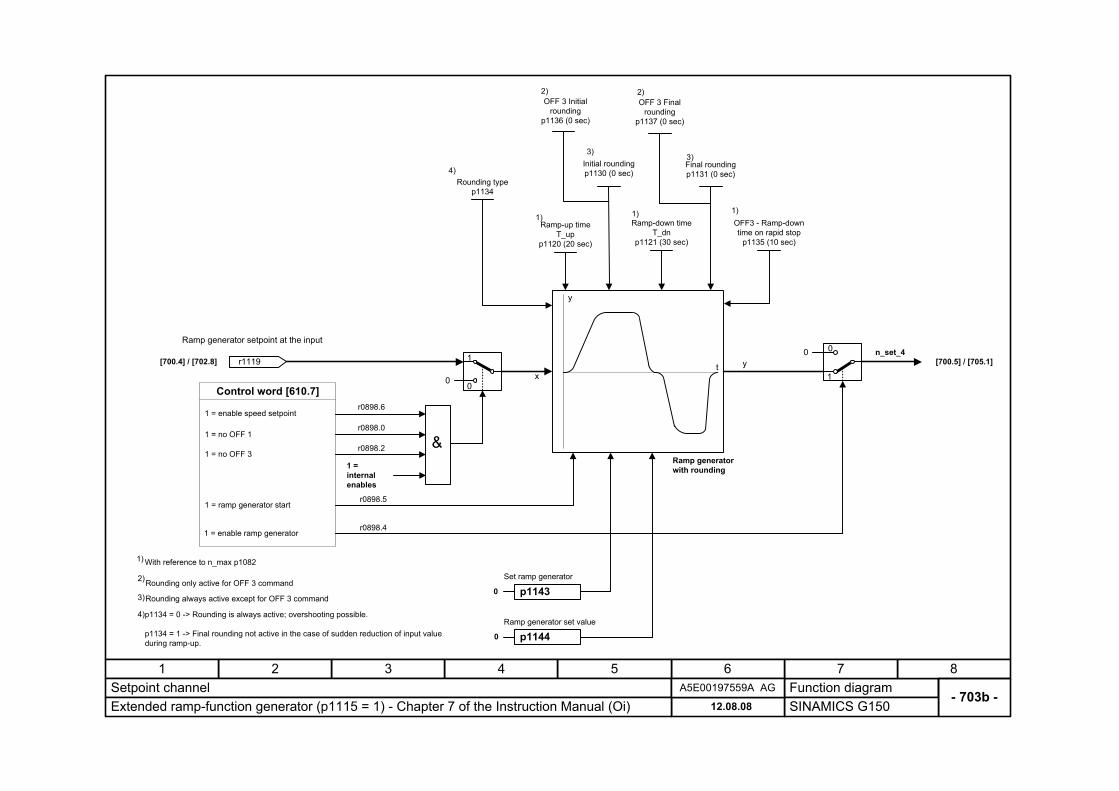
- 703b -Setpoint channel
SINAMICS G15012.08.08Extended ramp-function generator (p1115 = 1) - Chapter 7 of the Instruction Manual (Oi)A5E00197559A AG
yx
[700.4] / [702.8] [700.5] / [705.1]
r0898.5
r1119
Ramp generator setpoint at the input
Ramp-up time T_up
p1120 (20 sec)
Ramp-down time T_dn
p1121 (30 sec)
OFF3 - Ramp-down time on rapid stop
p1135 (10 sec)
1) 1)
3)
1 = enable ramp generator
1 = ramp generator start
1 = enable speed setpoint
Control word [610.7]
r0898.4
1
00 n_set_4
&1 = no OFF 1
1 = no OFF 31 = internal enables
1
00
r0898.6
r0898.0
r0898.2
1) With reference to n_max p1082
Ramp generator with rounding
t
y
Initial rounding p1130 (0 sec)
3)Final rounding p1131 (0 sec)
1)
OFF 3 Initial rounding
p1136 (0 sec)
OFF 3 Final rounding
p1137 (0 sec)
2)2)
Rounding type p1134
4)
p1143
p1144
Set ramp generator
Ramp generator set value
0
0
Rounding only active for OFF 3 command
Rounding always active except for OFF 3 command
p1134 = 0 -> Rounding is always active; overshooting possible.
p1134 = 1 -> Final rounding not active in the case of sudden reduction of input value during ramp-up.
2)
3)
4)
Function diagram87654321
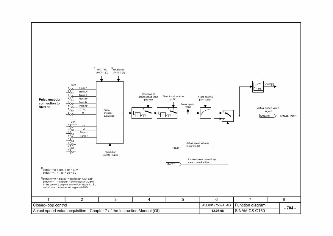
- 704 -Closed-loop control
SINAMICS G15012.08.08Actual speed value acquisition - Chapter 7 of the Instruction Manual (OI)A5E00197559A AG
[700.6] / [705.1]
r0063[1]
Pulse encoder evaluation r0063[0]
Actual speed value n_act
1 msX521
12345678
Track ATrack A*Track BTrack B*Track NTrack N*CTRL
M
X53112345678
UbM
Temp -Temp +
HTL/TTL p0405.1 (0)
uni/bipolar p0405.0 (1)
Resolution p0408 (1024)
1)p0405.1 = 0 -> HTL -> Ub = 24 V p0405.1 = 1 -> TTL -> Ub = 5 V
1) 2)
2)p0405.0 = 0 -> bipolar -> connection A/A*, B/B* p0405.0 = 1 -> unipolar -> connection A/M , B/M In the case of a unipolar connection, inputs A*, B*, and N* must be connected to ground GND.
Pulse encoder connection to SMC 30
Inversion of actual speed value
p0410.0n_act_filtering
p1441 (0.0)
Actual speed value of motor model
0
1
1
0
1
[700.5]
1 = sensorless closed-loop speed control active
Motor speed r0061
r1407.1
Direction of rotationp1821
1
0
1
Function diagram87654321
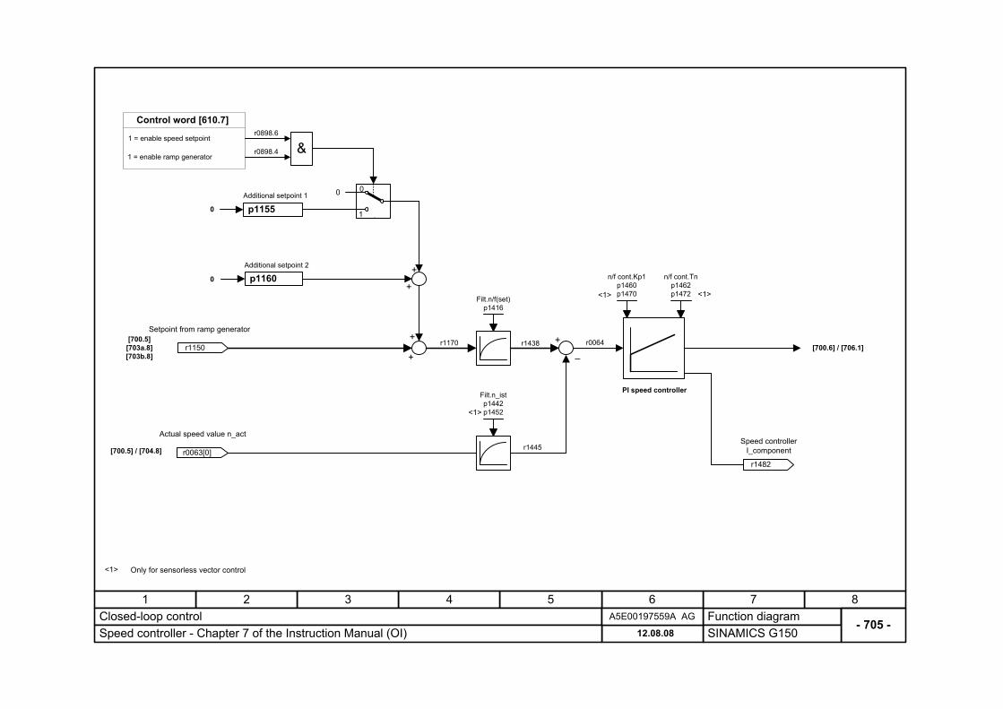
- 705 -Closed-loop control
SINAMICS G15012.08.08Speed controller - Chapter 7 of the Instruction Manual (OI)A5E00197559A AG
n/f cont.Kp1 p1460 p1470
n/f cont.Tn p1462 p1472
[700.5] [703a.8] [703b.8]
[700.6] / [706.1]–
[700.5] / [704.8]
Filt.n/f(set) p1416
r1438 r0064 r1150
Setpoint from ramp generator
p1155
p1160Additional setpoint 2
Additional setpoint 1
0
0
+
+
+
+
+
0
r0898.6
r0898.4 &
1
0
1 = enable ramp generator
1 = enable speed setpoint
Control word [610.7]
r0063[0]
Actual speed value n_act
r1482
Speed controller I_component
r1170
Filt.n_ist p1442 p1452
r1445
PI speed controller
Only for sensorless vector control<1>
<1> <1>
<1>
Function diagram87654321
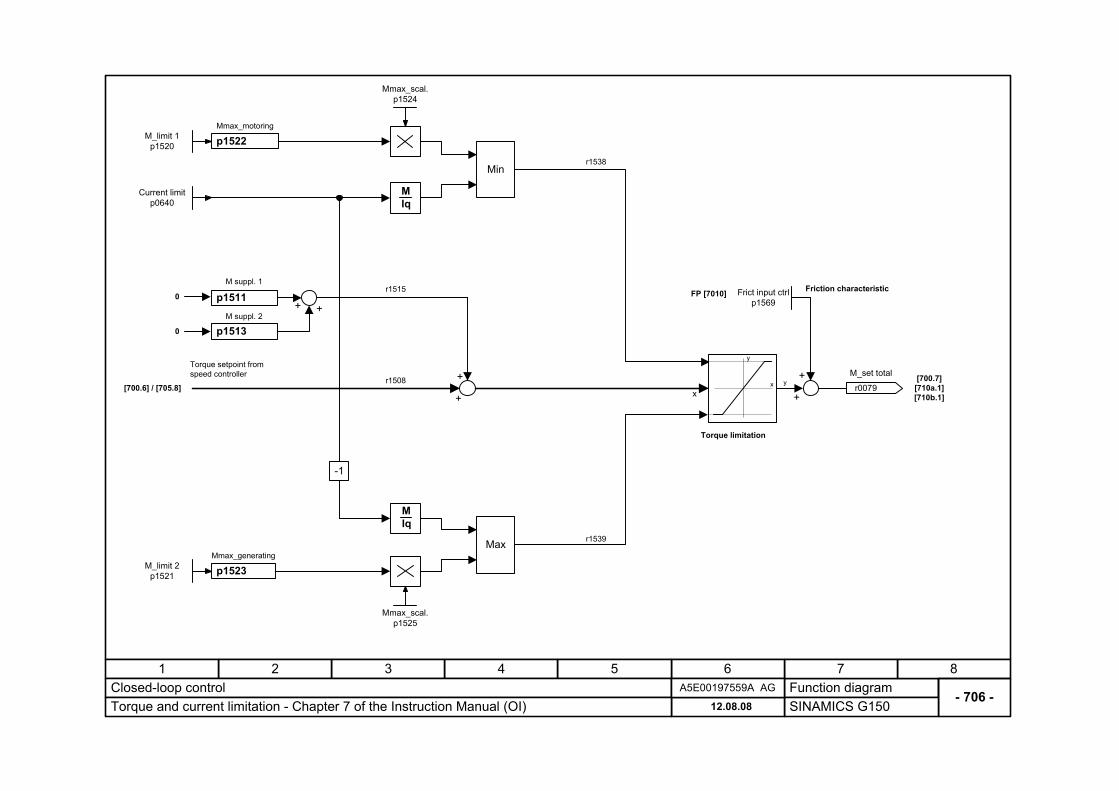
- 706 -Closed-loop control
SINAMICS G15012.08.08Torque and current limitation - Chapter 7 of the Instruction Manual (OI)A5E00197559A AG
[700.6] / [705.8][700.7]
[710a.1] [710b.1]
p1511M suppl. 1
0
+
+
r1515
Torque limitation
Torque setpoint from speed controller
y
y
xxr1508
Max
Min
p1522Mmax_motoring
M Iq
p1523Mmax_generating
M Iq
-1
Current limitp0640
M_limit 1 p1520
M_limit 2 p1521
Mmax_scal. p1524
Mmax_scal. p1525
r1538
r1539
r0079
M_set total
p1513M suppl. 2
0
++
+
+
Frict input ctrlp1569
FP [7010] Friction characteristic
Function diagram87654321
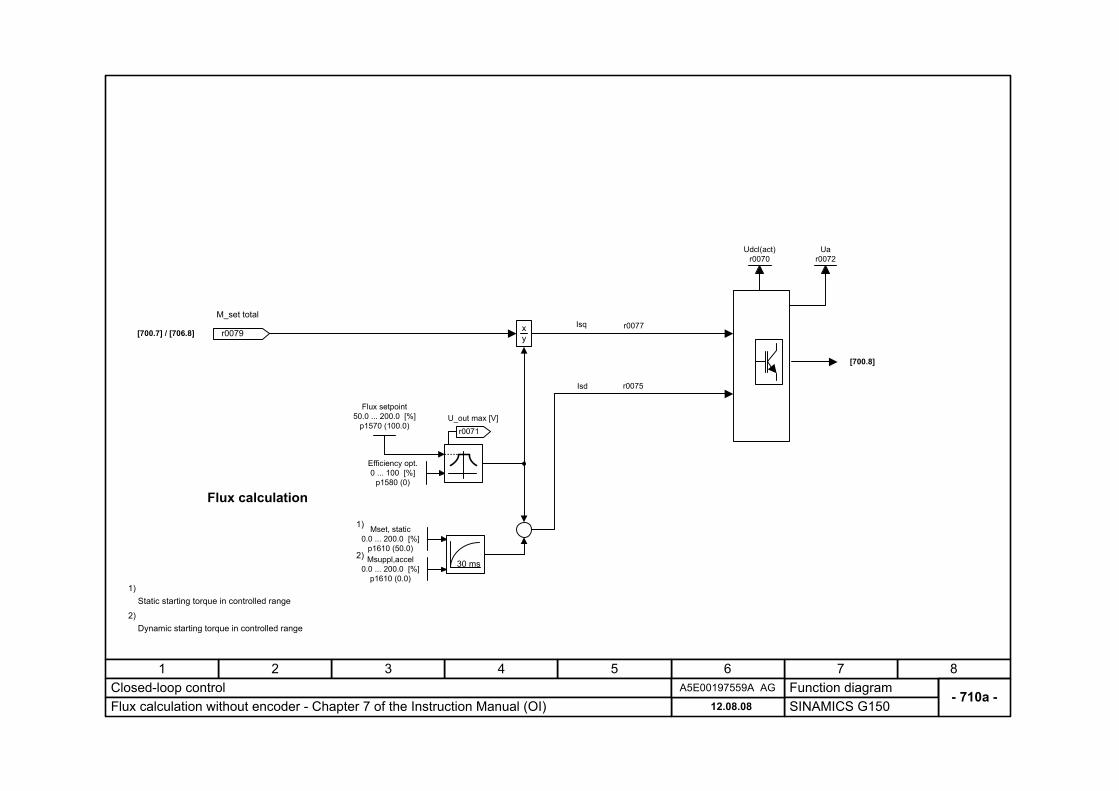
- 710a -Closed-loop control
SINAMICS G15012.08.08Flux calculation without encoder - Chapter 7 of the Instruction Manual (OI)A5E00197559A AG
x y
Udcl(act) r0070
Isq
Flux calculation
Efficiency opt. 0 ... 100 [%]
p1580 (0)
Mset, static 0.0 ... 200.0 [%]
p1610 (50.0)Msuppl,accel
0.0 ... 200.0 [%] p1610 (0.0)
30 ms
r0071U_out max [V]
[700.7] / [706.8]
[700.8]
r0079
M_set totalr0077
Static starting torque in controlled range1)
1)
2)
Dynamic starting torque in controlled range2)
Isd r0075
Ua r0072
Flux setpoint 50.0 ... 200.0 [%]
p1570 (100.0)
Function diagram87654321
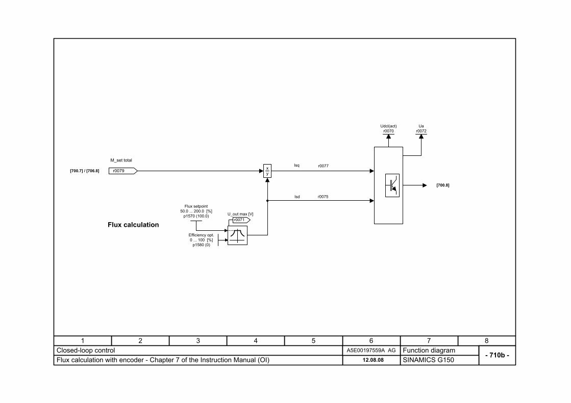
- 710b -Closed-loop control
SINAMICS G15012.08.08Flux calculation with encoder - Chapter 7 of the Instruction Manual (OI)A5E00197559A AG
x y
Udcl(act) r0070
Isq
Flux calculationEfficiency opt. 0 ... 100 [%]
p1580 (0)
r0071U_out max [V]
[700.7] / [706.8]
[700.8]
r0079
M_set totalr0077
Isd r0075
Ua r0072
Flux setpoint 50.0 ... 200.0 [%]
p1570 (100.0)
Function diagram87654321
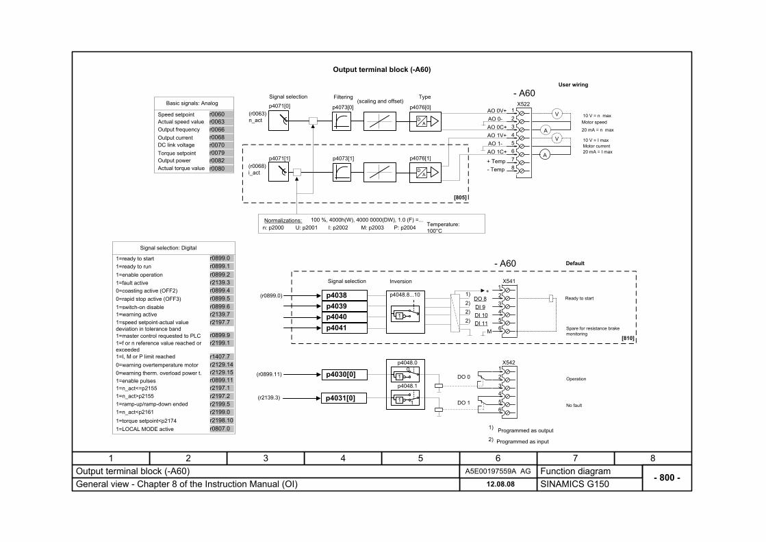
- 800 -Output terminal block (-A60)
SINAMICS G15012.08.08General view - Chapter 8 of the Instruction Manual (OI)A5E00197559A AG
User wiring
AO 0V+
4321
AO 0-
AO 1V+AO 0C+
5AO 1-6AO 1C+
X522
7+ Temp- Temp 8
DO 0
DO 1
X541
DO 8DI 9
DI 11
+
DI 10
- A60
X542
(scaling and offset)
AD
AD
p4073[0]
p4073[1]p4071[1]
p4071[0]
p4076[1]
p4076[0]
M
p4048.8...10
1
p4048.0
1
1
1
0
p4048.1
V
AV
A
Signal selection Filtering Type
Signal selection Inversion123456
Ready to start
4321
56
Operation
No fault
(r0063) n_act
(r0068) i_act
Speed setpoint
Output frequencyActual speed value
Basic signals: Analog
r0063r0066
r0060
Output currentDC link voltageTorque setpointOutput power
r0068r0070r0079r0082
Default
Motor current
10 V = n max
10 V = I max
20 mA = n max
20 mA = I max
Motor speed
(r0899.0)
(r0899.11)
(r2139.3)
Output terminal block (-A60)
n: p2000Normalizations:
U: p2001 I: p2002 M: p2003 P: p2004 Temperature: 100°C
100 %, 4000h(W), 4000 0000(DW), 1.0 (F) =...
1=ready to start
1=fault active
1=ready to run1=enable operation
Signal selection: Digital
r0899.1r0899.2r2139.3
r0899.0
0=coasting active (OFF2)0=rapid stop active (OFF3)1=switch-on disable1=warning active
r0899.4r0899.5r0899.6r2139.7
Spare for resistance brake monitoring
1)2)2)2)
1) Programmed as output2) Programmed as input
Actual torque value r0080
1=speed setpoint-actual value deviation in tolerance band1=master control requested to PLC
r2197.7
r0899.91=f or n reference value reached or exceeded
0=warning therm. overload power t.
1=I, M or P limit reached0=warning overtemperature motor
r1407.7r2129.14r2129.15
1=enable pulses1=n_act<=p21551=n_act>p21551=ramp-up/ramp-down ended
r0899.11r2197.1r2197.2r2199.5
1=n_act<p21611=torque setpoint<p2174
r2199.0r2198.10
r2199.1
1=LOCAL MODE active r0807.0
[805]
[810]
- A60
p4038p4039p4040p4041
p4030[0]
p4031[0]
Function diagram87654321
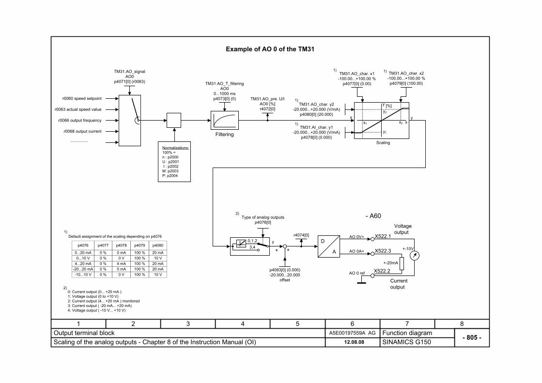
- 805 -Output terminal block
SINAMICS G15012.08.08Scaling of the analog outputs - Chapter 8 of the Instruction Manual (OI)A5E00197559A AG
D
A
AO 0V+
AO 0A+
AO 0 ref
X522.1
X522.2
X522.3
Voltage output
Current output
+-10V
+-20mA
Filtering
TM31.AO_T_filtering AO0
0...1000 ms p4073[0] (0)
TM31.AO_signal AO0
p4071[0] (r0063)
TM31.AO_pre. U/I AO0 [%] r4072[0]
r0060 speed setpoint
r0066 output frequency
...............
r0063 actual speed value
Scaling
TM31.AO_char. x1 -100.00...+100.00 %
p4077[0] (0.00)
TM31.AO_char. x2 -100.00...+100.00 %
p4079[0] (100.00)
TM31.AO_char. y2 -20.000...+20.000 (V/mA)
p4080[0] (20.000)x y
x1
y2
x2
y1
y
x
[%]
TM31.AI_char. y1 -20.000...+20.000 (V/mA)
p4078[0] (0.000)
0: Current output (0... +20 mA ) 1: Voltage output (0 to +10 V) 2: Current output (4... +20 mA ) monitored 3: Current output ( -20 mA... +20 mA) 4: Voltage output ( -10 V... +10 V)
2)
p4083[0] (0.000) -20.000...20.000
offset
r4074[0]y
++3,40,1,2
Type of analog outputs p4076[0]
2) - A60
Normalizations: 100% = n : p2000 U : p2001 I : p2002 M: p2003 P: p2004
Default assignment of the scaling depending on p40761)
1) 1)
1)
1)
Example of AO 0 of the TM31
r0068 output current
p4076
0...10 V0...20 mA
4...20 mA
-10...10 V-20...20 mA
p4077
0 V
0 mA4 mA
0 V
0 mA
p4078
0 %0 %0 %0 %0 %
p4079
10 V20 mA
20 mA
10 V20 mA
p4080
100 %100 %100 %100 %100 %

Function diagram87654321
- 810 -Output terminal block
SINAMICS G15012.08.08Digital inputs/outputs - Chapter 8 of the Instruction Manual (OI)A5E00197559A AG
0V
X541.2TM31.DO8_inversion
p4048.8 (0)
TM31.DO8_signal p4038 (r0899.0)
TM31.DO8 r4047.8
r0899.0 ready to start
r0899.2 operation
...............
r0899.1 ready to run
...............
- A60
DI/DO p4021. p4022. p4023. p4028.
8 8 8 8 89 9 9 9 9
10 10 10 10 1011 11 11 11 11
Index assignment depending on inputs/outputs 8 to 111)
1)
1)-1
0
1
X541.1
X541.6
P24
DI/DO 8
DI 8
DO 8
TM31.DI/O8_switchover DI <---> DO
p4028.8
0
1
1
TM31.DI8
r4022.8
TM31.DI8 inv.
r4023.8
p4047.
89
1011
p4048.
891011
1)
TM31.DI8 r4021.8
1)
2)
DI/DO Selection output
8 p40389 p4039
10 p404011 p4041
2) Parameter for selecting the digital outputs
Example of DI/DO 8 of the TM31
Function diagram87654321
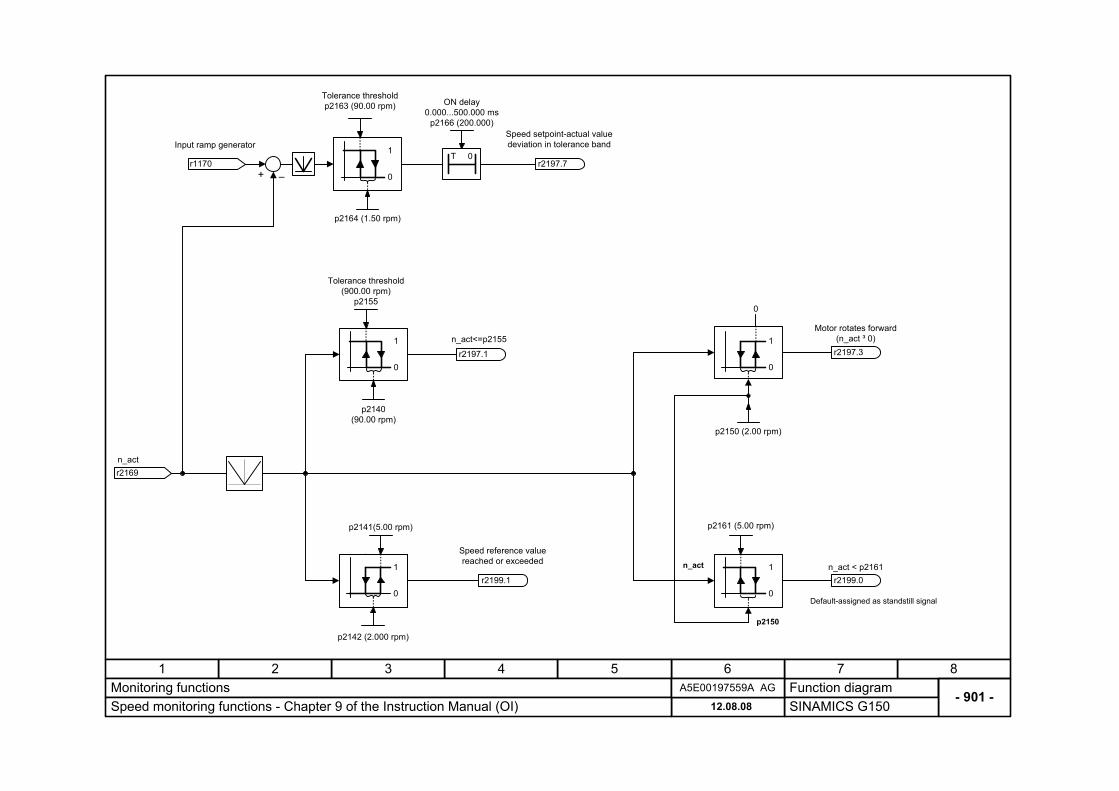
- 901 -Monitoring functions
SINAMICS G15012.08.08Speed monitoring functions - Chapter 9 of the Instruction Manual (OI)A5E00197559A AG
r1170
Input ramp generator
r2169n_act
+ –
T 0
ON delay 0.000...500.000 ms
p2166 (200.000)
Tolerance threshold p2163 (90.00 rpm)
p2164 (1.50 rpm)
0
1
0
0
1
p2150 (2.00 rpm)
Motor rotates forward (n_act ³ 0)r2197.3
0
1
0
1
p2141(5.00 rpm)
p2142 (2.000 rpm)
Speed reference valuereached or exceeded
r2199.1
Tolerance threshold (900.00 rpm)
p2155
p2140 (90.00 rpm)
0
1
p2161 (5.00 rpm)
0
1 n_act < p2161r2199.0
n_act
p2150
Default-assigned as standstill signal
n_act<=p2155
r2197.1
Speed setpoint-actual valuedeviation in tolerance band
r2197.7
Function diagram87654321
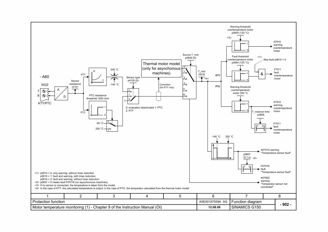
- 902 -Protection function
SINAMICS G15012.08.08Motor temperature monitoring (1) - Chapter 9 of the Instruction Manual (OI)A5E00197559A AG
Sensorresistance
r4101 A
D
0
1
0
1 &
Warning threshold overtemperature motor
p0604 (120 °C)
Fault thresholdovertemperature motor
p0604 (155 °C)
A7910 warning overtemperature motor
F7011 fault overtemperature motor
Skip fault p0610 = 0
Thermal motor model (only for asynchonous
machines)
0
1
11
3
2
10
KTY/PTC
X522
8
Correction (for KTY only)
- A60
Source T_mot p0600 (0)
T_mot r0035
-50 °C
0
1
Sensor type p4100 (0)
PTC resistance threshold 1650 ohm
T
R
1
0
250 °C
KTY
PTC
248 °C
-140 °C
7
0: evaluation deactivated 1: PTC 2: KTY
2
1
00
KTY
0
1
Warning thresholdovertemperature
motor 250 °C
A7910 warning overtemperature motor
T 0
T_motover time p0606
F7011 fault overtemperature motor
PTC
A07820 warning "Temperatur sensor not connected"
A07015 warning "Temperature sensor fault"
F07016 fault "Temperature sensor fault"
-140 °C
p0607 (0.1 s) <2>
T 0
<1> p0610 = 0: only warning, without Imax reduction p0610 = 1: fault and warning, with Imax reduction p0610 = 2: fault and warning, without Imax reduction
<2> p0607 = 0 masks fault F07016 (on asynchronous machines). <3> If no sensor is connected, the temperature is taken from the model. <4> In the case of KTY, the calculated temperature is output; in the case of PTC, the temperatur calculated from the thermal motor model
<1>
<3>
250 °C
<4>

Function diagram87654321
- 903 -Protection function
SINAMICS G15012.08.08Block protection and stall protection - Chapter 9 of the Instruction Manual (OI)A5E00197559A AG
r2169n_act
0.00...210 000.00 rpm p2175 (120.00)
n_act < p2175
T 0
p2177 (1.000) 0.000...65.000 s
ON delay
F7900
Motor blockedr2198.6
Speed controller at limit
r1407.7&
<20
&Current limiting controller active
r0056.12
Control type p1300
T 0
p2178 (0.010) 0.000...1.000 s
ON delay
F7902
Motor stalledr2198.71
Motor stalled
r1408.12
Error EMF
r1408.11
1) p1300 ³ 20 -> vector controls p1300 < 20 -> V/Hz characteristics
2) Only for vector control with sensor
1)
2)
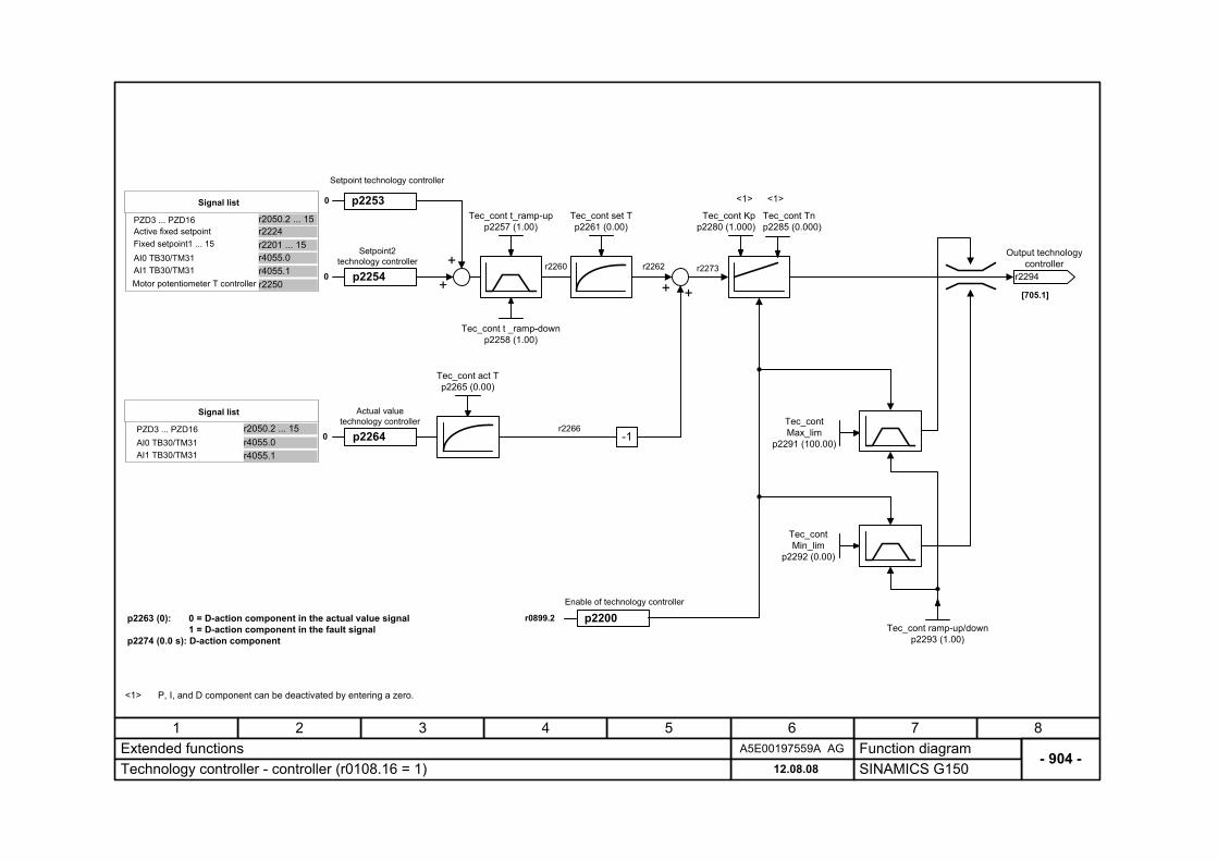
- 904 -Function diagram
87654321A5E00197559A AGExtended functions
SINAMICS G15012.08.08Technology controller - controller (r0108.16 = 1)
+
+
+
<1> P, I, and D component can be deactivated by entering a zero.
<1>
r2294
Output technologycontroller
Tec_cont t_ramp-up p2257 (1.00)
Tec_cont t _ramp-down p2258 (1.00)
Tec_cont set T p2261 (0.00)
Tec_cont act T p2265 (0.00)
Tec_cont Max_lim
p2291 (100.00)
Tec_cont Min_lim
p2292 (0.00)
Tec_cont ramp-up/down p2293 (1.00)
Tec_cont Kp p2280 (1.000)
<1>
Tec_cont Tn p2285 (0.000)
+
-1r2266
r2262 r2273r2260
p2200Enable of technology controller
r0899.2
[705.1]
p2253
Setpoint technology controller
0
p2254
Setpoint2technology controller
0
p22640
Actual valuetechnology controller
PZD3 ... PZD16
Fixed setpoint1 ... 15
Signal list
Active fixed setpoint
AI1 TB30/TM31AI0 TB30/TM31
PZD3 ... PZD16
Signal list
r2050.2 ... 15
AI1 TB30/TM31r4055.0r4055.1
AI0 TB30/TM31
Motor potentiometer T controller
p2263 (0): 0 = D-action component in the actual value signal 1 = D-action component in the fault signal
p2274 (0.0 s): D-action component
r2224r2201 ... 15
r2050.2 ... 15
r4055.0r4055.1r2250