general support-effective decomposition for multi
TRANSCRIPT

1
General Support-Effective Decomposition forMulti-Directional 3D Printing
Chenming Wu, Chengkai Dai, Guoxin Fang, Yong-Jin Liu, and Charlie C.L. Wang∗
Abstract—We present a method for fabricating general modelswith multi-directional 3D printing systems by printing differentmodel regions along with different directions. The core of ourmethod is a support-effective volume decomposition algorithmthat minimizes the area of the regions with large overhangs.A beam-guided searching algorithm with manufacturing con-straints determines the optimal volume decomposition, whichis represented by a sequence of clipping planes. While currentapproaches require manually assembling separate componentsinto a final model, our algorithm allows for directly printing thefinal model in a single pass. It can also be applied to models withloops and handles. A supplementary algorithm generates specialsupporting structures for models where supporting structures forlarge overhangs cannot be eliminated. We verify the effectivenessof our method using two hardware systems: a Cartesian-motionbased system and an angular-motion based system. A variety of3D models have been successfully fabricated on these systems.
Note to Practitioner Abstract—In conventional planar-layerbased 3D printing systems, supporting structures need to beadded at the bottom of large overhanging regions to preventmaterial collapse. Supporting structures used in single-material3D printing technologies have three major problems: beingdifficult to remove, introducing surface damage, and wastingmaterial. This research introduces a method to improve 3Dprinting by adding rotation during the manufacturing process. Tokeep the hardware system relatively inexpensive, the hardware,called a multi-directional 3D printing system, only needs to provideunsynchronized rotations. In this system, models are subdividedinto different regions, and then the regions are printed indifferent directions. We develop a general volume decompositionalgorithm for effectively reducing the area that needs supportingstructures. When supporting structures cannot be eliminated,we provide a supplementary algorithm for generating supportscompatible with multi-directional 3D printing. Our method canspeed up the process of 3D printing by saving time in producingand removing supports.
Index Terms—Volume decomposition, support, process plan-ning, multi-directional 3D printing, additive manufacturing
I. INTRODUCTION
CONSUMER-GRADE Additive Manufacturing (AM) de-vices (3D printers), particularly those based on Fused
Deposition Modeling (FDM) claim to have the ability to
Manuscript received March 16, 2019; revised June 18, 2019; acceptedAugust 8, 2019.
C. Wu and Y.-J. Liu are with Beijing National Research Center forInformation Science and Technology, Department of Computer Science andTechnology, Tsinghua University, Beijing, China.
C. Dai and G. Fang are with the Department of Design Engineering, DelftUniversity of Technology, Netherlands. Part of this work was completed whenthey worked at the Chinese University of Hong Kong.
C.C.L. Wang is with the Department of Mechanical and AutomationEngineering, The Chinese University of Hong Kong, Shatin, Hong Kong.
∗Corresponding Authors ([email protected])
Fig. 1. Snowman models fabricated with an off-the-shelf FDM printer(left) and our multi-directional printing system that adds only one rotationalaxis to the same printer (right). By allowing material accumulation alongdifferent directions in different regions, our system substantially reducessupport necessitation.
fabricate complex shapes, but the manufacturing process limitstheir abilities. Fabricating regions with large overhangs re-quires supporting structures (henceforth, supports) to preventmaterial collapse. While supports allow fabricating more com-plex models, they can be difficult to remove, waste material,and damage the model surface (ref. [1], [2]). These difficultiesgreatly reduce the flexibility of 3D printing in automatic andagile production environments. We develop a 3D printing sys-tem that adds rotational motion into the material accumulationprocess to enable AM with minimal or no supports.
Various approaches try to overcome the limitation of requir-ing supports during the fabrication process, such as optimizingthe topology of supports (e.g., [3], [4]), searching for an opti-mal printing direction [5], and reducing the usage of supportsby deformation [6] or model decomposition [7]–[9]. Existingdecomposition approaches often fabricate the components ofa model separately, requiring a manual “stitching” process toobtain the final result. In other words, they cannot completethe manufacturing process in one pass, and as such, do notneed to consider the constraint of collision-free fabrication.We aim to generate the 3D printing sequence for fabricatinga model with one pass along different directions, which wecall multi-directional 3D printing. As shown in Fig. 1, ourapproach can fabricate a model that typically requires a largearea of contact supports in a support-free manner.
Our paper makes the following technical contributions:
arX
iv:1
812.
0060
6v4
[cs
.RO
] 2
7 A
ug 2
019

2
• We formulate the process planning for multi-directional3D printing as a volume decomposition problem andsummarize the criteria of decomposition.
• We propose a support-effective volume decompositionalgorithm based on the beam-guided search that can beapplied to general 3D models with handles and loops.
• We develop a region-projection based method to generatesupports that are specially designed for multi-directional3D printing to address cases where completely support-free fabrication cannot be achieved.
We developed two types of multi-directional 3D printinghardware systems: a modified off-the-shelf FDM printer withone additional rotational degree-of-freedom (DOF) and anindustrial robotic arm that simulates a tilting table, providingtwo rotational DOFs. Physical fabrications conducted on bothsystems verify the effectiveness of our method.
II. RELATED WORK
Our work belongs to the interdisciplinary area of geometriccomputing and multi-axis fabrication, and we review the liter-ature on model decomposition, support-oriented optimization,and multi-axis 3D printing.
A. Decomposition for fabrication
Model decomposition is a well-studied geometry processingtechnique that has recently seen use in 3D printing applica-tions.
To solve the problem of printing large objects, Luo et al.[10] design a framework to decompose large objects thatexceed the working envelope of a 3D printer. They optimizethe outcome of segmentation with several objective functions,such as printability, aesthetic, and structural soundness. Vaneket al. [11] propose an optimization framework that prioritizesreducing printing time and material usage by converting solidsinto shells and applying a packing step to merge the shellsinto an optimized configuration for fabrication. Hu et al.[9] decompose a model into pyramidal parts for support-freeprinting. However, pyramidal decomposition is NP-hard, sothey construct a weak formulation of pyramidal constraints anddesign an efficient algorithm to solve for the decompositionproblem. Herholz et al. [7] also try to decompose a modelinto parts, but instead of following a pyramidal constraint,they allow slight deformation of models to produce piecesin the shape of height-fields. RevoMaker [12] can fabricatefreeform models on top of an existing electronic componentin a cubic shape. Again, the models need to be decomposedinto the shape of height-fields. Yao et al. [13] develop alevel-set method to deal with the problems of partitioningand packing. First, mesh segmentation constructs an initialvolume decomposition. Then, their results undergo alternatingoptimization via an iterative variational optimization method,where partitioning and packing energies are defined in vol-umetric space. Chen et al. [14] also decompose an inputmodel into a small number of parts that can be efficientlypacked for 3D printing. They use an algorithm that exploresthe decomposition and packing space with a prioritized andbounded beam search guided by local and global objectives.
Staircase artifacts generated by layer-based printing areconsidered a major type of defect in 3D printed models. Tosolve this problem, [15] creates a method for subdividingthe shape into parts that can be built in different directions.After printing all the individual parts, the 3D printed modelis manually assembled, which improves the visual qualityby reducing the staircase artifacts. Song et al. [16] proposean approach for fabricating large-scale models by combining3D printing and laser cutting in a coarse-to-fine fabricationprocess. Wei et al. [17] present a skeleton-based algorithm forpartitioning a 3D shell model into a small number of support-free parts, each of which has a specific printing direction thatleads to support-free fabrication. The method also minimizesseams and cracks by integrating the length of the cuts into theoptimization formulation. Muntoni et al. [8] recently proposeda decomposition algorithm for processing general 3D objectsinto a small set of non-overlapping height-field blocks. Thedirections of the height-fields are constrained to the principalaxes to solve the overlapping problem. These blocks can befabricated by moulding or 3D printing.
None of the discussed decomposition approaches considersthe collision-free constraint and sequence of manufacturing.Therefore, they cannot be directly applied to our multi-directional 3D printing system.
B. Support-oriented optimizationThough AM claims to have the ability to fabricate models
with complex shapes, the need for supports reduces the flexi-bility of production. Many prior approaches aim at optimizingeither the efficiency of production or the appearance of themodel. Several previous works use the volume of supportsas an optimization objective for generating effective supports.Vanek et al. [4] propose an algorithm for generating hier-archical support structures. MeshMixer [18] also provides awell-designed hierarchical pattern to generate efficient supportstructures. Dumas et al. [3] introduce a bridge-like supportstructure generation algorithm. Bridges are stronger and morestable than hierarchical structures while still maintaining man-ufacturing efficiency. However, with the development of fast3D printing technology, the contact area of the supports be-comes more critical than the volume, which is because a largercontact area requires more effort when manually removing thesupports, and the final model retains more surface artifacts.
Another thread of research focuses on changing the 3Dprinting orientation to reduce the contact area of supports.Hu et al. [6] design an orientation-driven shape deformationframework to adaptively adjust the orientation of regions withlarge overhangs. Zhang et al. [5] propose a double-layeredperceptual neural network, DL-ELM, to rank a list of possibleprinting directions, with the expectation that the best printingdirection prevents critical visual features from being damagedby additional supports. Similar to these works, we introducerotations into 3D printing to reduce the number of requiredsupports by minimizing their contact area.
C. Multi-axis 3D printingLayer-based approaches heavily restrict the flexibility and
efficiency of 3D printing. We review methods for adding more

3
Fig. 2. An illustration for our algorithm: (a) progressively determined results of planar clipping for generating the optimized decomposition, and (b) theinverse order of clipping planes that result in a sequence of regions for fabrication. The printing direction of each region is the normal of its base plane.Note that the orientation of a printing head is fixed during the procedure of physical fabrication, and the parts under fabrication are reoriented to realize themulti-directional 3D printing.
DOFs into the 3D printing process.Keating and Oxman [19] present a manufacturing platform
using 6-DOF provided by a robotic arm to fabricate models inboth additive and subtractive manners. Pan et al. [20] proposea 5-axis motion system similar to 5-axis CNC machines toaccumulate materials. A 6-DOF parallel kinematic Stewartplatform is presented in the work of Song et al. [21] for multi-directional AM. These systems only fabricate small modelswith simple shapes. Peng et al. [22] propose an On-the-FlyPrint system to enable fast, interactive fabrication by adding a2-DOF rotational platform to an off-the-shelf Delta 3D printer.This system can fabricate both solid and wireframe models.Using the On-the-Fly Print system, Wu et al. [23] propose analgorithm to generate a collision-free printing order for edgesin wireframe printing. Huang et al. [24] build a robotic arm3D printing system based on a 6-DOF KUKA robotic armand a customized extrusion head. They also propose a divide-and-conquer algorithm to search for a possible fabricationsequence that is both structurally stable and collision-free. Daiet al. [25] recently developed a support-free volume printingsystem equipped with a 6-DOF robotic arm. Shembekar etal. [26] present a method for conducting conformal 3D printingof freeform surfaces by collision-free trajectories, and thismethod has been validated on a 6-DOF robotic arm. Theseapproaches deposit materials along 3D tool paths and requirerelatively expensive devices and control systems to move allDOFs together during the fabrication process. In contrast, ourapproach decouples the motion for changing orientation fromthe motion for 3D printing. As a result, the decompositiongenerated by our algorithm can be used to supervise thefabrication of general models on a device with meager cost(e.g., the system introduced in Section VI-A).
The decomposition work presented in [27] for 3 + 2-axisadditive manufacturing relates closely to our approach. Theirwork employs a flooding algorithm to segment a given meshsurface into different regions, which can then be fabricatedalong with different directions without supports. However, thisapproach is limited in that it only works for tree-like models
with simple topologies. We propose a more general approachthat can process non-tree-like models as well as models withhandles and loops. Discussion and comparison with [27] canbe found in Section VI-C.
III. METHODOLOGY
A. Problem Statement
Given a modelM fabricated layer-by-layer on a base planeπ with a printing direction dπ , identify whether a face f withnormal nf is self-supported by
e(f, π) =
1 nf · dπ + sin (αmax) < 0,
0 otherwise.(1)
where αmax is the maximal self-supporting angle (ref. [6]).Face f is a risky face w.r.t π when e(f, π) = 1, otherwise itis a safe face. Note that dπ is the normal of π. Clearly, theneed for supports relates strongly with the printing direction,providing the opportunity for reducing or eliminating supportsby changing printing direction during manufacturing.
To supervise the operating multi-directional 3D printer, weneed to generate a decomposition of M where:
• M has N components such that
M =M1 ∪M2 ∪ · · · ∪MN = ∪Ni=1Mi (2)
with ∪ denoting the union operator;• Mi=1,··· ,N is an ordered sequence that can be
collision-freely fabricated with
πi+1 =Mi+1 ∩(∪ij=1Mj
)(3)
being the base plane of Mi+1 – here ∩ denotes theintersection operator;
• π1 is the working platform of a 3D printer;• All faces on a sub-region Mi are safe according to dπi
determined by πi.

4
We solve the weak-form problem by reducing the area ofrisky faces on each component Mi. That is, minimize
JG =∑i
∑f∈Mi
e(f, πi)A(f) (4)
where A(f) is the area of face f . While minimizing theobjective function (Eq.(4)), we need to ensure the fabricatingeach component is collision-free. For regions where faces arenot entirely safe, we generate supports specially designed formulti-directional 3D printing.
B. Our Approach
Multi-directional 3D printing a given model M requiresdetermining an ordered sequence of clipping planes γk (k =1, . . . , N − 1) that decomposes M into N components (seeFig.2(a)). We define the half-space of a clipping plane γkcontaining the 3D printing platform P as ‘below’, denotedby Γ−k ) and the half-space ‘above’ γk is Γ+
k . The clippingoperation gives the remained model by
Mk = Mk−1 \ Γ+k (5)
with M0 = M and ‘\’ denotes the subtraction operator onsolids. When every clipped sub-region in Γ+
k satisfies thecriteria of manufacturability (see Section III-C below), theinverse order of clipping gives the sequence of region printingfor multi-directional 3D printing. Specifically, we have
Mi = M(N−i) ∩ Γ+(N−i+1), πi = γ(N−i+1) (6)
with i = 1, · · · , N . The printing direction of a sub-regionMi
is given by the normal vector of γk pointing from Γ−k into Γ+k
with k = N − i+ 1. See Fig.2(b) for an illustration of usingthe inverse order of clipping to obtain the sequence for multi-directional 3D printing. Half-spaces defined by sequentiallyapplying all N clipping operations subdivide the <3 spaceinto N + 1 convex sub-space. The first k clipping operationsgenerate the Mi component (Eq.(6)) in a sub-space as in
Ωk = Γ−1 ∩ Γ−2 ∩ · · · ∩ Γ−k−1 ∩ Γ+k =
(∩k−1j=1 Γ−j
)∩ Γ+
k (7)
with Ω1 = Γ+1 . When needed, the supporting structure for the
component Mi will be generated in Ωk (k = N − i + 1)and progressively projected into the rest sub-space Ωj (j > k)until it can be merged with other supports or meets the printingplatform P (see Section V for details).
Candidates of clipping planes can be generated by1) uniformly sampling the Gaussian sphere to obtain 250
normals and2) applying a uniform shifting along each sampled normal
vector with an offset of 1mm.For all examples shown in this paper, this sampling strategygenerated around 15k ∼ 20k candidate clipping planes. Wedevelop a beam-guided search scheme to select an optimizedorder of clipping, which can significantly improve the local-optimum results obtained from a greedy scheme. Details willbe presented in Section IV.
The planar clipping methodology employed in this work canprocess general models with a high-genus number, addressingthe drawbacks in [28], [17], and [27], which could only
process models with skeletal-tree structures. Additionally, thealgorithm can be easily tailor-made to support a hardwaresystem with only one rotational axis (e.g., the system shownin Fig.5(a)). This is realized by generating samples nk on acircle of the Gaussian sphere satisfying nk · r = 0 with rbeing the axis of rotation. Moreover, we provide a supportgeneration solution to enable the fabrication of all models ona multi-directional 3D printing system.
C. Criteria for Decomposition
We now define the criteria for finding an optimal sub-regionMi according to a clipping plane γk (k = N−i+1) for multi-directional 3D printing. Here πi denotes the correspondingbase plane of γk.
Criterion I: ∀f ∈ Mi, e(f, πi) = 0 – i.e. all faces on Mi
are self-supported.
Minimization of the objective function (Eq.(4)) imposes thiscriterion, ensuring the manufacturability of the region aboveγk.
Criterion II: The model Mk obtained from the clipping byγk must be connected to the printing platform P .
This criterion prevents unmanufacturable configurations forthe region below γk by avoiding the generation of “floating”regions, which require supports when printed.
The next criterion avoids collisions between the printer headand the platform.
Criterion III: The printing platform P and the clipping planeγk satisfy Γ+
k ∩ P = ∅ (i.e., P is below γk).
Note that we do not explicitly prevent collision between theprinter head and already fabricated regions as the clippingroutine that generates sub-regions fromM already guaranteesthis. All regionsMj (j<i) are below the base plane πi (i.e. theclipping plane γ(N−i+1)) because the sequence of 3D printingis the inverse order of clipping.
In practice, we cannot always find a decomposition satis-fying Criterion I for all components. For such a scenario, aweak form for support-free is adopted to aim at generating asmaller area of overhang during fabrication.
When changing from one printing direction to anotherprinting direction, the following drawbacks are introduced:• The visual artifact of a curve is formed at the interface
of two neighboring regions;• It takes extra time for the machine to move from one
orientation to the other – the printing process is slower.Therefore, we generally prefer a solution with fewer compo-nents, which can be achieved by considering the followingcriterion of clipping.
Criterion IV: We prefer a large solid volume for the regionabove a clipping plane.
In summary, the volume decomposition ofM is consideredoptimized when it satisfies all the above criteria. Two schemesdeveloped in the next section compute the optimal decompo-sition.
5
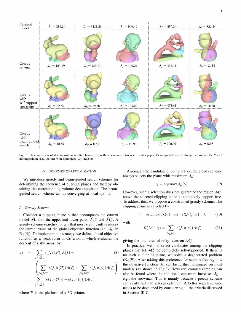
Fig. 3. A comparison of decomposition results obtained from three schemes introduced in this paper. Beam-guided search always determines the “best”decomposition (i.e., the one with minimized JG (Eq.(4)).
IV. SCHEMES OF OPTIMIZATION
We introduce greedy and beam-guided search schemes fordetermining the sequence of clipping planes and thereby ob-taining the corresponding volume decomposition. The beam-guided search scheme avoids converging at local optima.
A. Greedy Scheme
Consider a clipping plane γ that decomposes the currentmodel Mc into the upper and lower parts, M+
c and M−c . Agreedy scheme searches for a γ that most significantly reducesthe current value of the global objective function (i.e., JG inEq.(4)). To implement this strategy, we define a local objectivefunction as a weak form of Criterion I, which evaluates thedescent of risky areas, by:
JL =∑f∈Mc
e(f, π(P))A(f)− (8)
∑f∈M−
c
e(f, π(P))A(f) +∑
f∈M+c
e(f, π(γ))A(f)
=
∑f∈M+
c
(e(f, π(P))− e(f, π(γ)))A(f)
where P is the platform of a 3D printer.
Among all the candidate clipping planes, the greedy schemealways selects the plane with maximum JL:
γ = arg max JL(γ). (9)
However, such a selection does not guarantee the region M+c
above the selected clipping plane is completely support-free.To address this, we propose a constrained greedy scheme. Theclipping plane is selected by
γ = arg max JL(γ) s.t. R(M+c , γ) = 0 (10)
withR(M+
c , γ) =∑
f∈M+c
e(f, π(γ))A(f) (11)
giving the total area of risky faces on M+c .
In practice, we first select candidates among the clippingplanes that let M+
c be completely self-supported. If there isno such a clipping plane, we solve a degenerated problem(Eq.(9)). After adding this preference for support-free regions,the objective function JG can be further minimized on mostmodels (as shown in Fig.3). However, counterexamples canalso be found where the additional constraint increases JG –e.g., the snowman. This is mainly because a greedy schemecan easily fall into a local optimum. A better search schemeneeds to be developed by considering all the criteria discussedin Section III-C.

6
B. Beam-Guided Search Scheme
As aforementioned, in many cases, it is not guaranteed tofind a support-free decomposition for every sub-region – i.e.,Criterion I is not satisfied for some regions. To provide ageneral solution, we reformulate this criterion into a weakform as a local objective function. Specifically, we search fora clipping plane γk that leads to
minR(MN−k+1, γk) (12)
with R(·, ·) evaluating the total area of risky faces as definedin Eq.(11). Criterion II and III are imposed by excludingthose unsatisfactory clipping planes from the set of candidates.Similarly, to avoid generating too many small fragments whendecomposing an input modelM, clipping operations that leadto a sub-region with volume less than V (M)/w are prevented.Here, w is a user-specified parameter to control the maximalnumber of components (i.e., w from 10 to 12 is used in ourtests).
Beam search [29] is an efficient search technique that hasbeen widely used to improve the results of best-first greedysearch. A breadth-first strategy is employed to build a searchtree that explores the search space by expanding the set of mostpromising nodes instead of only the best node at each level.It has been successfully used in a variety of areas, especiallyin geometric configuration search tasks for 3D printing (e.g.,[10], [14]). Our approach introduces a progressive relaxationroutine to conduct the breadth-first search.
The most challenging part in solving our volume decompo-sition is integrating the restrictive Criterion I (and its weakform) as an objective function presented in Eq.(12). Thisimportant step ensures that the beam search is broad enoughto include both the local optimum and configurations that maylead to a global optimum. In contrast with the traditionalusage of a beam search algorithm that keeps the b mostpromising results, our beam-guided search algorithm startsfrom an empty beam with the most restrictive requirementof R(MN−k+1, γk) < δ, where δ is a tiny number (e.g.,δ = 0.1 is used in all our tests). Candidate clipping planesthat satisfy this requirement and remove larger areas of riskyfaces have higher priority when filling the b beams. If thereare still empty beams, we relax δ by letting δ = 5δ until all bbeams are filled. Details of our beam-guided search algorithmare presented below.
The algorithm starts from b empty beams Bj (j = 1, . . . , b),where each beam Bj = (M(Bj),L(Bj)) contains a remainingmodel M(Bj) and an ordered list of clipping planes, L(Bj),that forms M(Bj). In our implementation, only the lastelement of a list needs to be stored in Bj , as the rest of theprior elements in the list can be traced through a backwardlink. By using the progressive relaxation routine, each beamcan be extended by adding a new clipping plane into its listand obtaining an updated remaining model. In the next round,apply progressive relaxation to all valid clipping results forall b remaining models, prioritizing the removal of more riskyfaces. Repeat the extension process of beam Bj until any ofthe following terminal conditions is satisfied on the remainingmodel M(Bj)
Algorithm 1: Beam-Guided Search
Input: Input mesh M.Output: An optimized set of decomposition as Mi.
1 Build a set of uniformly sampled candidate planes Π(Section III-B) that ∀γ ∈ Π, γ ∩ P = ∅ (Criterion III);
2 Initialize b empty beams as ∀j, Bj = (null, null);3 B1 = (M, null);4 repeat
/* Preparing clipping candidates */5 Initialize a maximum heap of clipping as G = ∅;6 forall Bj do7 if M(Bj) 6= null then8 forall γ ∈ Π do9 The clipping plane γ decomposes M(Bj)
into M+ and M−;10 if (V (M+) ≥ 1
wV (M)) AND (M− isconnected to P) then
11 Evaluate JG according to L(Bj);12 Insert the tuple (M−,M+,L(Bj), γ)
into G with JG as the key;
/* Progressive relaxation */13 δ = 0.1 and k = 0;14 while k < b do15 Initialize a maximum heap G as buffer;16 while G 6= ∅ do17 Pop (M−,M+,L, γ) from the top of G;18 if R(M+, γ) < δ then19 Add γ at the tail of L;20 Let Bk+1 = (M−,L) and k = k + 1;21 else22 Evaluate JG according to L;23 Insert the tuple (M−,M+,L, γ) into G
with JG as the key;
24 Let G = G and δ = 5δ;
/* Checking terminal condition */25 forall Bj do26 if (V (M(Bj)) < 1
wV (M)) OR(R(M(Bj), π(P)) = 0) then
27 Evaluate JG according to L(Bj);28 Bj = (null,L(Bj));
29 until ∀j, M(Bj) = null;30 return the decomposition that gives the minimal JG;
• Small Volume: The volume of the remaining modelM(Bj) has small volume – i.e., V (M(Bj)) < 1
wV (M);• Self-Supported: The remaining model M(Bj) is com-
pletely self-supported as R(M(Bj), π(P)) = 0.
The search also terminates when no beam can be furtherextended.
Each beam corresponds to a list of clipping planes that givesa decomposition model M. The decomposition that leads tothe minimal value of JG (Eq.(4)) is considered the optimizedsolution for our multi-directional 3D printing. Pseudo-code of

7
our beam-guided search algorithm is given in Algorithm 1. Weuse the method of discarding results close to already selectedones, which is proposed in [10], to avoid filling the beamby similar results. Example results and a comparison againsttwo other greedy (constrained and unconstrained) schemes canbe found in Fig.3. The beam-guided search gives the bestdecomposition on all models.
V. SUPPORT GENERATION
After relaxing the hard-constraint of creating a support-freemodel decomposition into minimizing the area of risky faces,JG, the scheme for generating supports is considerately impor-tant for models that still have risky faces after decomposition.To tackle this problem, we propose a new structure calledprojected support that ensures the fabrication of remainingoverhanging regions through collision-free multi-directional3D printing.
For a decomposition that results in a sequence of sub-regions S = Mi with base plane πi corresponding to eachsub-region Mi, the printing direction di is the normal vectorof πi. Thus, the overhanging region onMi with respect to theprinting direction di can be detected and supporting structuresadded along the direction (−di). Here, we select the tree-likesupport [4] that merges the supporting structures for differentoverhanging regions when they are near each other. In fact, ourprogressive projection algorithm is general and can be appliedto different patterns of supports, such as the bridge-like support[3] or other denser supports [30].
Unlike the existing algorithms that generate supports byprojecting along a fixed printing direction, in our case, theprojection should be conducted along with different directionsin different regions. Without loss of generality, the i-th compo-nentMi falls in a sub-space Ωk formed by the first k clippingplanes – as shown in Eq.(7) with k = N − i+ 1. The supportfor the overhang onMi is generated along the inverse printingdirection (−di) and projected onto the base plane (i.e., the k-th clipping plane, γk). Next, the structure is projected into anew sub-space Ωk+1 and along a new direction (−di−1). Theprojection repeats until this structure can be merged with otherstructures or meets the printer’s platform P . Fig.4(b) showssupports generated by our progressive projection algorithmdisplayed in different colors when they are in different sub-spaces Ωk. The pseudo-code of our progressive projectionalgorithm is given in Algorithm 2.
After applying the volume decomposition algorithm, we usethe uniformly sampling strategy to detect all overhang types –including point-overhang, edge-overhang and face-overhang.Sampling interval R is a parameter selected by the diameterof the deposition nozzle and struts. We use R = 3mm forprinting with a 0.8mm diameter nozzle and R = 2mm forprinting with a 0.4mm diameter nozzle. For each sub-meshMs and its associated sub-space Ωs, an ideal configuration ofsupport structures Cs should satisfy Cs ⊂ Ωs with a minimalnumber of points that contact the input model. We use themethod proposed in [4] to ensure that the newly generatednodes of the tree are inside Ωs during the merging procedure.This guarantees that the corresponding connected structures
(a) Tree-like supports (b) Projected supports
Fig. 4. The sparse tree-like supporting structures for 3D printing along witha fixed direction (a) and the progressively projected supports generated by ouralgorithm for multi-directional 3D printing (b). Note that, fewer supports areneeded for the multi-directional printing. To avoid the issues of stability raisedby gravitational torques, we incorporate dynamic struts defined in Eq.(13) togenerate projected support structures in our system.
Algorithm 2: Progressive Projection
Input: Components of M in a sequence S.Output: Support structures T
1 Initialize an empty set T = ∅ for support-structures;2 for i = N, . . . , 1 do3 if R(Mi, πi) > 0 then4 Generate support Ci for Mi inside ΩN−i+1;5 Merge Ci into T ;
6 Extend T along the direction of (−di) until meetingthe base plane πi or the component Mi;
7 return T ;
are inside the convex space Ωs. We set the maximal self-supporting angle for sparse tree-like supports to 30 and adopta heuristic greedy-based method [4] to progressively mergepairs of supporting structures when they are close to eachother.
Moreover, considering the stability issue raised by gravita-tional torque when printing along with different directions, wepropose the following function for selecting the diameter Rpof a projected supporting strut Cp ⊂ Ωk.
Rp = (1 + λ‖∑i
Vi(ci × g)‖)R/4 (13)
where ‖∑i Vi(ci × g)‖ is the torque on top of Cp, and ci
and Vi are the centroid and the volume of the supporting strutconnected to Cp. λ is a user-defined parameter to determinethe diameter of projected supports, and we empirically set itas 10−6.
VI. EXPERIMENTAL RESULTS
We have implemented the proposed search algorithms inC++ and Python programs and tested them on a PC withtwo Intel E5-2698 v3 CPUs and 128GB RAM. To prove theeffectiveness of our algorithm, we use a conservative choice ofthe maximal self-supporting angle as αmax = 45. In practice,this parameter highly depends on a 3D printer’s capability, andup to 70 can be achieved by advanced 3D printers, such asthe one used in [17]. The slicing software for conventionalFDM, Ultimaker Cura [31], is used to create planar slices and

8
Fig. 5. Two different hardware setups for multi-directional printing havebeen built to verify the effectiveness of our volume decomposition approach.(Left) A Cartesian-space-based 4DOF printer modified from an off-the-shelfFDM printer with an additional degree-of-freedom to provide the capability ofrotation. (Right) A joint-space-based 5DOF system consisting of an industrial6DOF robotic arm and a fixed FDM extruder.
Fig. 6. Reachability map of our robotic arm, where different colors representdifferent levels of reachability (i.e., from worst to best in colors Red, Yellow,Green, SkyBlue and Blue). The fixed FDM extruder is placed at the centerof a region with high reachability (i.e., the region circled in dash lines).
tool-paths according to the printing directions determined inour algorithm. The generated g-code for fabrication is sentto the motion-control module of the hardware. Two differenthardware platforms have been used to verify the effectivenessof decomposition, with different configurations for navigatingthe motions of material extrusions. One is a Cartesian-space-based system with 4-DOF in motion, and the other hardwareplatform is a joint-space-based system [28] that is built on anindustrial robotic arm equipped with a fixed FDM extruder.
A. Cartesian-space-based hardware
The hardware setup of the 4DOF multi-directional printer isdeveloped on top of an off-the-shelf FDM printer (i.e., CrealityCR-10S and Ultimaker 2+) by adding a rotational platform.Inspired by the 4-axis CNC machine, a turbine-shaft structuredriven by a step-motor is built vertically and fixed into the baseof the 3D printer platform, which will be moved together. Notethat, the additional cost of this hardware system is only about240 USD, which is cost-effective when comparing to deviceswith synchronized multi-axis motion. Moreover, we design aneasy-to-calibrate platform, shown in the left of Fig.5, whichallows ±60 collision-free rotation.
During the manufacturing process, the motion of the printerheader is fully controlled by the 3D printer itself. The newlyadded motor for rotation is only used to realize the orientationchange between sub-models from one to the next. An Arduinochipboard controls the rotation applied to the platform of 3Dprinting. Note that as a step motor is used, only a limitednumber of orientations can be realized. This manufacturingconstraint is considered while generating sample points onthe Gaussian sphere for clipping planes. The process of 3Dprinting on this 4DOF system can be found in the top row ofFig.7 as well as the supplementary video.
B. Joint-space-based hardware
The principle of the 4DOF system can also be extended to5DOF by using a tilting table with two rotational DOFs. In ourexperimental tests, a 6DOF robotic arm is used to demonstratethe functionality of our method with 5DOF motion, althougha robotic arm provides much lower positioning accuracy. Thehardware setup is composed of a UR5 robotic arm, andan FDM extruder fixed on a frame and some other controlcomponents. As the extruder is fixed to obtain better adhesionin our system, the change of printing directions and positions isrealized by the inverse poses of a printing platform attached tothe UR5 robotic arm. Considering the accuracy of positioningthat can be achieved on UR5 [32] and the speed of fabrication,we employ a 0.8mm diameter nozzle in our system for materialdeposition.
Because of the hardware constraints of the UR5 robotic arm(e.g., limited ranges of joints), not every point with a givenorientation can be realized. The reachability of points insidethe working envelope is very sensitive to the relative positionof the nozzle in the coordinate system of the UR5’s base frame,which needs to be optimized to enhance the reachability. Firstof all, the workspace of a robotic arm is uniformly sampledinto points. For each point in the Cartesian space, we randomlysample an additional 100 points on the unit sphere around thepoint with orientations towards the center of the sphere. Thereachability map can be generated by Reuleaux [33]. As shownin Fig.6, we placed the extruder of our setup at the center ofa region with the highest reachability.
The middle and bottom rows of Fig.7 present the progressiveresults of models fabricated on the 5DOF multi-directional3D printing system. Our method can successfully decomposea given model into support-free components to be fabricatedone by one.
C. Results and Discussion
We applied our volume decomposition algorithm to a varietyof models. In addition to the models shown in Figs.1 and 3,we tested our system on models with higher genus-number(see Figs.7 and 8). Our algorithm can greatly reduce or eveneliminate the need for supports on these models. Models thatstill require supports add these supports to only very smallregions of the model, and we compare these results to aconventional planar 3D printer in Fig.7.
The major advantage of our approach compared with [27]is the ability to handle models with handle and loop topology

9
Fig. 7. The progressive results of fabricating models with our 4DOF multi-directional 3D printing system (the top row) and a 5DOF system realized on arobotic arm (the middle and bottom rows).
(see the models in Fig.8). For example, when applying thealgorithm of Xu et al. [27] to the Kitten model of Fig.8, theirflooding algorithm is stuck at the fourth region, as shown inFig.9. When applying their method to the Bunny model withgenus-zero topology, the result is similar to ours (see Fig.10),though our result has a slightly smaller JG. Another problemwith their method is that the collision-free constraint has notbeen explicitly incorporated into the computation – i.e., thecollision between the printer head and the already fabricatedear may happen when printing the other ear of the Bunny.
Letting JG = 0 is sufficient but unnecessary for a modelM to be support-freely fabricated by the multi-directional 3Dprinting system. In other words, when our algorithm returnsa decomposition with JG 6= 0 for a model, it is still possibleto have a solution for support-free decomposition that wasnot found. This is partially because of the local optimumdetermined by the beam-guided search. Our sampling strategydiscretizes continuous 3D space, which can also raise thisproblem.
When generating sub-models for 4DOF printing, the result-ing decomposition depends on the selection of the rotational
axis. As shown in Fig.11, when specifying different axes e.g.,ra = (1, 0, 0) and rb = (0.829,−0.559, 0) as rotational axis,the decomposition results in different levels of self-support.Specifically, we obtain JG = 126.58 and JG = 87.33 whenusing ra and rb as the rotation axis respectively. This bringsin a new parameter, the rotational axis, to further optimize thedecomposition. A simple solution is to discretely sample a fewpossible rotational axes, then select the one that leads to theminimal JG after decomposition.
Our approach employs a sampling strategy for generatingcandidates of clipping planes, which are then used for com-puting the decomposition and sequence of multi-directional3D printing. In one way, this helps us impose manufacturingconstraints easily – e.g., limiting the rotational axis, computingorientations that can be physically realized by step-motors, andexcluding the singular and the collided poses for a robotic arm.On the other hand, this also limits the space of computation.The variables in our computations are not continuous, whichmeans we may miss the “real” optimal clipping planes. Toaddress this, future work should consider further adjustingclipping planes via continuous optimization by using the

10
Fig. 8. The decomposition results fabricated by our system with 4DOF and 5DOF in motion, where the resultant value of JG is also reported.
TABLE ICOMPUTATIONAL STATISTIC
Trgl. Computing Part JG Support Volume Printing TimeModel Fig. # Type Time # Before After Fixed Dir. Multi-Dir. Fixed Dir. Multi-Dir.Bunny 3 12,420 5DOF 94 sec. 5 314.26 10.85 130.59 0.00 42 min. 55 min.Kitten 3 10,000 5DOF 98 sec. 5 1481.36 0.81 893.58 0.00 220 min. 187 min.Bimba 3 12,156 5DOF 105 sec. 5 560.49 20.86 382.46 14.42 108 min. 134 min.
Fertility 3 16,172 5DOF 314 sec. 6 555.84 200.60 310.25 156.53 59 min. 70 min.Snowman 3 10,000 5DOF 104 sec. 5 822.34 9.98 370.92 7.33 188 min. 240 min.
1 4DOF 64 sec. (Total: 192 min.) 5 11.84 12.62 242 min.Yoga 8 11,254 5DOF 298 sec. 5 613.89 25.92 392.17 39.92 189 min. 234 min.
8 4DOF 88 sec. (Total: 266 min.) 4 98.51 74.56 207 min.Mechanical- 8 15,348 5DOF 52 sec. 2 698.09 0.00 843.45 0.00 56 min. 39 min.
Mounter 8 4DOF 34 sec. (Total: 102 min.) 2 0.00 0.00 39 min.
Fig. 9. The progressive result of applying the flooding based algorithm [27]to the Kitten model, which is stuck at the fourth region due to handle topology.
planes determined in our approach as an initial guess.Table I shows the computational statistics of models tested
in this paper. For the 4DOF decomposition, we report boththe average time for the beam-search according to a givenrotational axis and the total time for searching all possiblerotational axes (reported in the bracket), where 180 possiblerotational axes are considered. The computational efficiencyof our approach is acceptable when compared with the 3D
Fig. 10. The comparison of our result (left with JG = 10.85) and the resultof [27] (right with JG = 31.55).
printing time (i.e., around a few hours in general). We measureprinting time using Ultimaker Cura (Version 3.6.0) [31] withthe settings of 0.4mm layer height and 20% grid infill. Thevolumes of support needed for 3D printing along a fix direction(denoted by Fixed Dir.) and our method (denoted by Multi-Dir.) are reported in Table I. We also report the comparison

11
Fig. 11. When selecting different axes for 4DOF fabrication, the decomposi-tion gives different results – (left) JG = 126.58 for using (1, 0, 0) as the ro-tational axis and (right) JG = 87.33 for rotating around (0.829,−0.559, 0).The rotational axes are shown in red. As can be found in the top row,supporting structures need to be added below the ear of the bunny by therotational axis (1, 0, 0). This is eliminated by using (0.829,−0.559, 0) asthe rotational axis (see the bottom row).
of printing time. The reason why longer time is needed formulti-directional 3D printing on some models is the hollowedvolume is less on the decomposed components.
Another weakness of this decomposition-based multi-directional 3D printing approach is the relatively weak stiff-ness of the model. As already studied in [28], smaller Young’smodulus is observed on the specimens generated by this ap-proach during the tensile tests. The weak adhesion of materialsmainly causes this at the interface between two regions. Oneof our future research questions is how to design specialstructures at the interface between different regions to enhancethe mechanical strength of adhesion.
VII. CONCLUSION
We present a volume decomposition framework for thesupport-effective fabrication of general models via multi-directional 3D printing. A beam-guided search computes thedecomposition while avoiding local optima. While prior workcan only fabricate models with skeletal tree structures, ourmethod can apply to models with multiple loops and handles.We also provide a support generation scheme that allows ourframework to fabricate all types of models. The frameworkcan incorporate manufacturing constraints such as the numberof rotational axes and the realizable configurations duringthe orientation sampling process. As a result, our algorithmsupports both the 4DOF and the 5DOF systems. We verify theeffectiveness of our approach by creating a variety of modelson multiple hardware setups.
ACKNOWLEDGMENT
This work was partially supported by the seed fund of TUDelft IDE Faculty, the Natural Science Foundation of China(61725204, 61521002, 61628211), Royal Society-Newton Ad-vanced Fellowship (NA150431) and MOE-Key Laboratory ofPervasive Computing. The authors would like to thank NikitaHaduong at the University of Washington for polishing thewriting.
REFERENCES
[1] W. Gao, Y. Zhang, D. Ramanujan, K. Ramani, Y. Chen, C. B. Williams,C. C. Wang, Y. C. Shin, S. Zhang, and P. D. Zavattieri, “The status, chal-lenges, and future of additive manufacturing in engineering,” Computer-Aided Design, vol. 69, pp. 65–89, 2015.
[2] E. Sachs, M. Cima, P. Williams, D. Brancazio, and J. Cornie, “Threedimensional printing: rapid tooling and prototypes directly from a CADmodel,” Journal of Engineering for Industry, vol. 114, no. 4, pp. 481–488, 1992.
[3] J. Dumas, J. Hergel, and S. Lefebvre, “Bridging the gap: Automatedsteady scaffoldings for 3d printing,” ACM Trans. Graph., vol. 33, no. 4,pp. 98:1–98:10, July 2014.
[4] J. Vanek, J. A. Galicia, and B. Benes, “Clever support: Efficient supportstructure generation for digital fabrication,” in Computer GraphicsForum, vol. 33, no. 5. Wiley Online Library, 2014, pp. 117–125.
[5] X. Zhang, X. Le, A. Panotopoulou, E. Whiting, and C. C. Wang,“Perceptual models of preference in 3D printing direction,” ACM Trans.Graph., vol. 34, no. 6, p. 215, 2015.
[6] K. Hu, S. Jin, and C. C. L. Wang, “Support slimming for single materialbased additive manufacturing,” Computer-Aided Design, vol. 65, pp. 1–10, 2015.
[7] P. Herholz, W. Matusik, and M. Alexa, “Approximating free-formgeometry with height fields for manufacturing,” Computer GraphicsForum, vol. 34, no. 2, pp. 239–251, 2015.
[8] A. Muntoni, M. Livesu, R. Scateni, A. Sheffer, and D. Panozzo, “Axis-aligned height-field block decomposition of 3D shapes,” ACM Trans.Graph., 2018.
[9] R. Hu, H. Li, H. Zhang, and D. Cohen-Or, “Approximate pyramidalshape decomposition,” ACM Trans. Graph., vol. 33, no. 6, pp. 213:1–213:12, 2014.
[10] L. Luo, I. Baran, S. Rusinkiewicz, and W. Matusik, “Chopper: Partition-ing models into 3D-printable parts,” ACM Trans. Graph., vol. 31, no. 6,pp. 129:1–129:9, Nov. 2012.
[11] J. Vanek, J. Galicia, B. Benes, R. Mech, N. Carr, O. Stava, and G. Miller,“Packmerger: A 3D print volume optimizer,” in Computer GraphicsForum, vol. 33, no. 6. Wiley Online Library, 2014, pp. 322–332.
[12] W. Gao, Y. Zhang, D. C. Nazzetta, K. Ramani, and R. J. Cipra,“RevoMaker: Enabling multi-directional and functionally-embedded 3Dprinting using a rotational cuboidal platform,” in Proceedings of the 28thAnnual ACM Symposium on User Interface Software and Technology,2015, pp. 437–446.
[13] M. Yao, Z. Chen, L. Luo, R. Wang, and H. Wang, “Level-set-basedpartitioning and packing optimization of a printable model,” ACM Trans.Graph., vol. 34, no. 6, p. 214, 2015.
[14] X. Chen, H. Zhang, J. Lin, R. Hu, L. Lu, Q. Huang, B. Benes, D. Cohen-Or, and B. Chen, “Dapper: Decompose-and-pack for 3d printing,” ACMTrans. Graph., vol. 34, no. 6, pp. 213:1–213:12, Oct. 2015.
[15] W. Wang, C. Zanni, and L. Kobbelt, “Improved surface quality in 3Dprinting by optimizing the printing direction,” in Computer GraphicsForum, vol. 35, no. 2. Wiley Online Library, 2016, pp. 59–70.
[16] P. Song, B. Deng, Z. Wang, Z. Dong, W. Li, C.-W. Fu, and L. Liu,“Cofifab: coarse-to-fine fabrication of large 3D objects,” ACM Trans.Graph., vol. 35, no. 4, p. 45, 2016.
[17] X. Wei, S. Qiu, L. Zhu, R. Feng, Y. Tian, J. Xi, and Y. Zheng, “Towardsupport-free 3D printing: A skeletal approach for partitioning models,”IEEE Transactions on Visualization and Computer Graphics, vol. 24,no. 10, pp. 2799–2812, Oct 2018.
[18] R. Schmidt and N. Umetani, “Branching support structures for 3Dprinting,” in ACM SIGGRAPH 2014 Studio, ser. SIGGRAPH ’14. NewYork, NY, USA: ACM, 2014, pp. 9:1–9:1.
[19] S. Keating and N. Oxman, “Compound fabrication: A multi-functionalrobotic platform for digital design and fabrication,” Robotics andComputer-Integrated Manufacturing, vol. 29, no. 6, pp. 439–448, 2013.

12
[20] Y. Pan, C. Zhou, Y. Chen, and J. Partanen, “Multitool and multi-axiscomputer numerically controlled accumulation for fabricating conformalfeatures on curved surfaces,” ASME Journal of Manufacturing Scienceand Engineering, vol. 136, no. 3, 2014.
[21] X. Song, Y. Pan, and Y. Chen, “Development of a low-cost parallelkinematic machine for multidirectional additive manufacturing,” ASMEJournal of Manufacturing Science and Engineering, vol. 137, no. 2,2015.
[22] H. Peng, R. Wu, S. Marschner, and F. Guimbretiere, “On-the-fly print:Incremental printing while modelling,” in Proceedings of the 2016 CHIConference on Human Factors in Computing Systems. ACM, 2016,pp. 887–896.
[23] R. Wu, H. Peng, F. Guimbretiere, and S. Marschner, “Printing arbitrarymeshes with a 5dof wireframe printer,” ACM Trans. Graph., vol. 35,no. 4, p. 101, 2016.
[24] Y. Huang, J. Zhang, X. Hu, G. Song, Z. Liu, L. Yu, and L. Liu,“Framefab: robotic fabrication of frame shapes,” ACM Trans. Graph.,vol. 35, no. 6, p. 224, 2016.
[25] C. Dai, C. C. L. Wang, C. Wu, S. Lefebvre, G. Fang, and Y.-J.Liu, “Support-free volume printing by multi-axis motion,” ACM Trans.Graph., vol. 37, no. 4, pp. 134:1–134:14, July 2018.
[26] A. V. Shembekar, Y. J. Yoon, A. Kanyuck, and S. K. Gupta, “Gener-ating robot trajectories for conformal three-dimensional printing usingnonplanar layers,” Journal of Computing and Information Science inEngineering, vol. 19, no. 3, p. 031011, 2019.
[27] K. Xu, L. Chen, and K. Tang, “Support-free layered process planningtoward 3 + 2-axis additive manufacturing,” IEEE Transactions onAutomation Science and Engineering, vol. 16, no. 2, pp. 838–850, April2019.
[28] C. Wu, C. Dai, G. Fang, Y. J. Liu, and C. C. L. Wang, “RoboFDM:A robotic system for support-free fabrication using FDM,” in 2017IEEE International Conference on Robotics and Automation (ICRA),May 2017, pp. 1175–1180.
[29] B. T. Lowerre, “The harpy speech recognition system.” Ph.D. dis-sertation, Carnegie Mellon University, Pittsburgh, PA, USA, 1976,aAI7619331.
[30] P. Huang, C. C. L. Wang, and Y. Chen, “Algorithms for layeredmanufacturing in image space,” in ASME Advances in Computers andInformation in Engineering Research, 2014, pp. 377–410.
[31] Ultimaker. Ultimaker Cura: Advanced 3D printing software,made accessible. [Online]. Available: https://ultimaker.com/en/products/ultimaker-cura-software
[32] C.J.Kruit, “A novel additive manufacturing approach using a multipledegrees of freedom robotic arm,” Master’s thesis, Delft University ofTechnology, August 2013.
[33] A. Makhal and A. K. Goins, “Reuleaux: Robot base placement byreachability analysis,” in 2018 Second IEEE International Conferenceon Robotic Computing (IRC), Jan 2018, pp. 137–142.
Chenming Wu received the B.Eng. degree in elec-tronic information engineering from the Beijing Uni-versity of Technology, China, in 2015. He is cur-rently a Ph.D. candidate in the Department of Com-puter Science and Technology, Tsinghua University,China. His current research interests are intelligentdesign, computational fabrication and robotics.
Chengkai Dai is currently a Ph.D. candidate of theDepartment of Design Engineering at Delft Uni-versity of Technology. His research area includesrobotics, geometry computing and computationaldesign.
Guoxin Fang received the B.Eng. degree in me-chanical engineering from the Beijing Institute ofTechnology, Beijing, China, in 2016. He is currentlypursuing the Ph.D. degree with the Department ofDesign Engineering at Delft University of Technol-ogy. His research area includes advanced manufac-turing, computational design and robotics.
Yong-Jin Liu is currently a professor with theDepartment of Computer Science and Technology,Tsinghua University, China. He received his B.Engdegree from Tianjin University, China, in 1998, andthe PhD degree from the Hong Kong Universityof Science and Technology, Hong Kong, China, in2004. His research interests include computationalgeometry, computer graphics and computer-aideddesign. He is a senior member of the IEEE and amember of ACM.
Charlie C.L. Wang is currently a Professor of Me-chanical and Automation Engineering and Directorof Intelligent Design and Manufacturing Instituteat the Chinese University of Hong Kong (CUHK).Before that, he was a tenured Professor and Chairof Advanced Manufacturing at Delft University ofTechnology (TU Delft), The Netherlands. He re-ceived the Ph.D. degree (2002) from Hong KongUniversity of Science and Technology in mechanicalengineering, and is now a Fellow of the AmericanSociety of Mechanical Engineers (ASME) and the
Hong Kong Institute of Engineers (HKIE). His research areas include geo-metric computing, intelligent design and advanced manufacturing.