general specifications - motortong.com specifications 1) three-phase 230v class series (1/8 to 20hp)...
TRANSCRIPT

FECA-TE-116 07/2010
General Specifications

1. Standard specifications
1) Three-phase 230V class series (1/8 to 20HP) Items Specifications
Type (FRNE1S-2U)
F12 F25 F50 001 002 003 005 007 010 015 020
Nominal applied motor
*1 [HP]
1/8 1/4 1/2 1 2 3 5 7.5 10 15 20
Ou
tpu
t ra
tin
gs
Rated capacity *2
[KVA] 0.3 0.6 1.2 2.0 3.2 4.4 6.8 10 13 19 24
Rated voltage *3
[V]
Three-phase 200 to 240V (With AVR function)
Rated current *4
[A]
0.8
(0.7) 1.5
(1.4) 3.0
(2.5) 5.0
(4.2) 8.0
(7.0) 11
(10) 17
(16.5) 25
(23.5) 33
(31) 47
(44) 60
(57)
Overload capability
*5
150% of rated current for 1min, 200% of rated current for 0.5s
Rated frequency 50, 60Hz
Inp
ut
rating
s
Main power supply Three-phase, 200 to 240V, 50/60Hz
Voltage/frequency variations
Voltage: +10 to -15% (Voltage unbalance: 2% or less *6
), Frequency: +5 to -5%
Rated current
*7
[A]
With DCR
0.57 0.93 1.6 3.0 5.7 8.3 14.0 21.1 28.8 42.2 57.6
Without DCR
1.1 1.8 3.1 5.3 9.5 13.2 22.2 31.5 42.7 60.7 80.0
Required power supply capacity
*8
[kVA] 0.2 0.3 0.6 1.1 2.0 2.9 4.9 7.4 10 15 20
Bra
kin
g Torque
*9 [%] 150 100 70 40 20
Torque *10
[%] 150
DC braking Starting frequency: 0.1 to 60.0Hz, Braking time: 0.0 to 30.0s, Braking level: 0 to 100% of rated current
Braking transistor Built-in
Applicable safety standards
UL508C, C22.2 No.14, EN50178: 1997
Enclosure(IEC60529) IP20 / UL open type
Cooling method Natural cooling Fan cooling
Mass [lbs(kg)] 1.3 (0.6)
1.3 (0.6)
1.5 (0.7)
1.8 (0.8)
3.7 (1.7)
3.7 (1.7)
5.1 (2.3)
7.5 (3.4)
7.9 (3.6)
13 a)
(6.1)
16 a)
(7.1)
Note: *1 Standard 4-pole motor *2 Rated capacity is calculated by regarding the output rated voltage as 230V for three-phase 230V class series. *3 Output voltage cannot exceed the power supply voltage. *4 The load shall be reduced so that the continuous operating current is the rated current in parenthesis or less if the carrier frequency
is set to 4kHz or above. *5 For 20HP, if ambient temperature exceeded 45°C(104°F), the overload capability is obtained after continuous operation at 85% of
rated current.
*6 3(5.2.3))(IEC61800 67%[V] voltage average phase-Three
[V] voltage Min.[V] voltage Max.unbalance Voltage
If this value is 2 to 3%, use an AC reactor (ACR). *7 The currents are calculated on the condition that the inverters are connected to power supply of 500kVA, %X=5%. *8 Obtained when a DC reactor (DCR) is used. *9 Average braking torque when a motor of no load decelerates. (Varies with the efficiency of the motor.) *10 Average braking torque obtained by use of an external braking resistor. (Standard type available as option)

2) Three-phase 460V class series (1/2 to 20HP)
Items Specifications
Type (FRNE1S-4U)
F50 001 002 003 005 007 010 015 020
Nominal applied motor
*1 [HP]
1/2 1 2 3 5 7.5 10 15 20
Ou
tpu
t ra
tin
gs
Rated capacity *2
[kVA] 1.2 2.0 2.9 4.4 7.2 10 14 19 24
Rated voltage *3
[V]
Three-phase, 380 to 480V (With AVR function)
Rated current *4
[A]
1.5 2.5 3.7 5.5 9.0 13 18 24 30
Overload capability
*5
150% of rated current for 1min, 200% of rated current for 0.5s
Rated frequency 50, 60Hz
Inp
ut
rating
s
Main power supply Three-phase, 380 to 480V, 50/60Hz
Voltage/frequency variations
Voltage: +10 to -15% (Voltage unbalance: 2% or less *6
), Frequency: +5 to -5%
Rated current
*7
[A]
With DCR
0.85 1.6 3.0 4.4 7.3 10.6 14.4 21.1 28.8
Without DCR
1.7 3.1 5.9 8.2 13.0 17.3 23.2 33.0 43.8
Required power supply capacity
*8
[kVA] 0.6 1.1 2.0 2.9 4.9 7.4 10 15 20
Bra
kin
g Torque
*9 [%] 100 70 40 20
Torque *10
[%] 150
DC braking Starting frequency: 0.1 to 60.0Hz, Braking time: 0.0 to 30.0s, Braking level: 0 to 100% of rated current
Braking transistor Built-in
Applicable safety standards
UL508C, C22.2 No.14, EN50178: 1997
Enclosure(IEC60529) IP20 / UL open type
Cooling method Natural cooling Fan cooling
Mass [lbs(kg)] 2.4 (1.1)
2.6 (1.2)
3.7 (1.7)
3.7 (1.7)
5.1 (2.3)
7.5 (3.4)
7.9 (3.6)
13 a)
(6.1)
16 a)
(7.1)
Note: *1 Standard 4-pole motor *2 Rated capacity is calculated by regarding the output rated voltage as 460V for three-phase 460V class series. *3 Output voltage cannot exceed the power supply voltage. *4 The load shall be reduced so that the continuous operating current is the rated current in parenthesis or less if the carrier frequency
is set to 4kHz or above. *5 For 20HP, if ambient temperature exceeded 45°C(104°F), the overload capability is obtained after continuous operation at 85% of
rated current.
*6 3(5.2.3))(IEC61800 67%[V] voltage average phase-Three
[V] voltage Min.[V] voltage Max.unbalance Voltage
If this value is 2 to 3%, use an AC reactor (ACR). *7 The currents are calculated on the condition that the inverters are connected to power supply of 500kVA, %X=5%. *8 Obtained when a DC reactor (DCR) is used. *9 Average braking torque when a motor of no load decelerates. (Varies with the efficiency of the motor.) *10 Average braking torque obtained by use of an external braking resistor. (Standard type available as option)

3) Single-phase 230V class series (1/8 to 3HP) Items Specifications
Type (FRNE1S-7U)
F12 F25 F50 001 002 003
Nominal applied motor *1
[HP] 1/8 1/4 1/2 1 2 3
Ou
tpu
t ra
tin
gs
Rated capacity *2
[kVA] 0.3 0.6 1.2 2.0 3.2 4.4
Rated voltage *3
[V]
Three-phase, 200 to 240V (With AVR function)
Rated current *4
[A]
0.8 (0.7)
1.5 (1.4)
3.0 (2.5)
5.0 (4.2)
8.0 (7.0)
11 (10)
Overload capability 150% of rated current for 1min, 200% of rated current for 0.5s
Rated frequency 50, 60Hz
Inp
ut
rating
s
Main power supply Single-phase, 200 to 240V, 50/60Hz
Voltage/frequency variations
Voltage: +10 to -10%, Frequency: +5 to -5%
Rated current
*5
[A]
With DCR
1.1 2.0 3.5 6.4 11.6 17.5
Without DCR
1.8 3.3 5.4 9.7 16.4 24.0
Required power supply capacity
*6
[kVA] 0.3 0.4 0.7 1.3 2.4 3.5
Bra
kin
g Torque
*7 [%] 150 100 70 40
Torque *8
[%] 150
DC braking Starting frequency: 0.1 to 60.0Hz, Braking time: 0.0 to 30.0s, Braking level: 0 to 100%
Braking transistor Built-in
Applicable safety standards
UL508C, C22.2 No.14, EN50178:1997
Enclosure(IEC60529) IP20 / UL open type
Cooling method Natural cooling Fan cooling
Mass [lbs(kg)] 1.3 (0.6)
1.3 (0.6)
1.5 (0.7)
2.0 (0.9)
4.0 (1.8)
5.3 (2.4)
Note *1 Standard 4-pole motor *2 Rated capacity is calculated by regarding the output rated voltage as 230V for three-phase 230V class series. *3 Output voltage cannot exceed the power supply voltage. *4 The load shall be reduced so that the continuous operating current is the rated current in parenthesis or less if the carrier frequency
is set to 4kHz or above. *5 The currents are calculated on the condition that the inverters are connected to power supply of 500kVA, %X=5%. *6 Obtained when a DC reactor (DCR) is used. *7 Average braking torque when a motor of no load decelerates. (Varies with the efficiency of the motor.) *8 Average braking torque obtained by use of an external braking resistor (standard type available as option)

2. Common specifications
Items Specifications Remark
Ou
tpu
t fr
eq
uen
cy
ad
justm
en
t
Maximum output frequency
25 to 400Hz adjustable
Base frequency
25 to 400Hz adjustable
Starting frequency
0.1 to 60.0Hz, Holding time 0.0 to 10.0s
Carrier frequency
• 0.75 to 15kHz adjustable Note) The carrier frequency may drop automatically according to the ambient
temperature or output current to protect the inverter.) • Carrier frequency modulation: Motor noise may reduced by modulating the carrier
frequency.
Accuracy • Analog setting: ±0.2% or less of Maximum frequency (25±10°C(77±50°F))
• Keypad: ±0.01% or less of Maximum frequency (-10 to +50°C(14 to 122°F))
Setting resolution • Analog setting :1/3000 of maximum frequency
• Keypad setting :0.01Hz(99.99Hz or below), 0.1Hz(100.0 to 400.0Hz)
• Link setting :1/20000 of maximum frequency or 0.01Hz(Fixed)
Con
tro
l
Control method • V/f control ・Dynamic torque vector control
• V/f control or Dynamic torque vector control (With speed feedback ; PG option)
Voltage/freq. characteristic 230V
class
Possible to set output voltage at base frequency and at maximum respectively from 80 to 240V. AVR control can be turned ON or OFF.
2 points (Arbitrary voltage and frequency can be set.) Arbitrary voltage (0 to 240V), Arbitrary frequency (0 to 400Hz)
460V class
Possible to set output voltage at base frequency and at maximum respectively from 160 to 500V. AVR control can be turned ON or OFF.
2 points (Arbitrary voltage and frequency can be set.) Arbitrary voltage (0 to 240V), Arbitrary frequency (0 to 400Hz)
Torque boost • Auto-torque boost (For constant torque load) • Manual torque boost: Torque boost value can be set 0.0 to 20.0 percent. • Selectable by load characteristics (Constant torque load, Variable torque load)
Starting torque 200% or more at setting frequency 0.5Hz with Slip compensation and auto-torque boost.
Start/Stop Keypad operation : Start/Stop with , keys (Standard keypad)
Start/Stop with , , keys
(Multi-function keypad: Option)
External signals : Forward (reverse) rotation, stop command (capable of 3-wire operation)
(Digital input) coast-to-stop command, external alarm, alarm reset, etc.
Link operation : RS-485communication(Equipped as standard) and Field Bus communication (option)
Operation command switch: Remote/local switch, link switch
Frequency setting Key operation: Can be set with , keys (Possible to lock the setting data)
Analog input : -10VDC to 0 to +10VDC / -100% to 0 to 100% (Terminal [12]) : +4 to 20mADC / 0 to 100% (Terminal [C1]),
Terminal [C1] can accept 0 to +10VDC / 0 to 100% by changing the switch.
Multi-frequency: 16 frequencies at maximum are selectable.
UP/DOWN operation: The frequency rises or lowers while the digital input signal is turned on.
Link operation: Can be set with RS-485 communications and field bus communications (option).
Frequency setting change: Two types of frequency settings can be switched with an external signal (Digital input). Frequency setups through communication or Multi-frequency are also possible.
Auxiliary frequency setting: Inputs at terminal [12], [C1] can be added to the main setting as auxiliary frequency settings.
Inverse action: The digital input signal and function code setting sets or switches between the normal and inverse actions 0 to +10VDC / 0 to 100% can be switched to +10 to 0VDC / 0 to 100% +4 to +20mADC / 0 to 100% can be switched to +20 to 0mADC / 0 to 100%
Pulse train input: Max. 30kHz at maximum frequency (Optional PG interface card is necessary)

Items Specifications Remark
Con
tro
l Acceleration / Deceleration time
・0.00 to 3600s
・Acceleration and deceleration pattern can be selected from 4 types: Linear,
・S-curve (weak), S-curve (strong), Curvilinear (constant output max. capacity)
・Shutoff of the operation command coasts the motor to decelerate and stop.
・Exclusive Dec. time for Force to Stop can be set. (0.00 to 3600s) S-curve will be canceled during Force to Stop.
・ACC. / DEC. time for Jogging operation can be set. (0.00 to 3600s)
Frequency limiter (High/low frequency)
・High and low limiters can be set. ( setting range: 0 to 400Hz)
Bias frequency Bias of set frequency and PID command can be set in the range between 0 and ±100%.
Gain for frequency setting
The analog input gain can be set in the range from 0 to 200%.
Jump frequency setting
3 operation points and their common jump hysteresis width (0 to 30Hz) can be set.
Timer operation Operate and stop by the time set with keypad. (1 cycle operation)
Jogging operation
Jogging operation is possible by key (Standard keypad), / key (Multifunction keypad) or digital input. (ACC. / DEC. time for Jogging operation can be set. (ACC. and DEC. time is common.)
Restart after momentary power failure
• The inverter restarts upon recovery from power failure without stopping the motor. • Restarting frequency is selectable from Starting frequency or output frequency at power
failure..
Current limit (Hardware current limiting)
• Hardware current limiting is used avoiding overcurrent tripping of the inverter, when impact load change or momentary power failure that can be responded software current limiting. (Hardware current limiting can be inactive.)
Slip compensation • Compensate the lowering the motor speed and get the stabilized operation. • Adjustable compensation time constant, Cancellation during ACC. / DEC or at constant
power range is possible.
Droop control • Motor speed will be reduced according to load torque.
Torque limiter • Control output torque so that output torque is preset limiting value or less. • Second limiting value can be possible. • Filter function to reduce the shock when Torque limiter 1/2 is changed.
Current limiter • Control output current so that output current is preset limiting value or less.
Overload stopping • When detected torque or current exceed the preset value, Inverter will decelerate and stop or will coast to stop.
PID control PID control for process control and dancer control is possible. • PID command: Keypad, Analog input (Terminal [12], [C1]), RS-485 communication • Feed back value: Analog input (Terminal [12], [C1]) • Accessory functions
Alarm output (absolute value alarm, deviation alarm) Normal operation/inverse operation Sleep function Anti-reset wind-up function PID output limiter Integration reset/hold
• Speed control (Slip compensation, A,B channel /B channel) PG interface card (option) Required
Auto search for idling motor's speed
Motor speed is searched automatically before running motor and motor is pulled in without stopping.

Items Specifications Remark
Co
ntr
ol
Automatic Deceleration
• Control the output frequency and suppress the regenerative energy from motor so as to avoid Overvoltage trip
Deceleration Characteristics
Make the motor loss increase during deceleration so as to reduce the regenerative energy from motor and avoid Overvoltage trip.
Auto-energy saving operation
Control the output voltage so as to minimize the sum of motor loss and inverter loss at constant speed.
Active drive The output frequency is automatically reduced to suppress the overload protection trip of the inverter caused by an increase in the IGBT junction temperature or the ambient temperature, motor load or the like.
Auto-tuning The motor parameters are automatically tuned.
Cooling fan ON/OFF control
Detects inverter internal temperature and stops cooling fan when the temperature is low. An external output is issued in a transistor output signal.
Second motor parameters
• One inverter can drive the another motor changing from a motor. The function data set for second motor are base frequency, rated current, torque boost, Electronic overload protection for motor, slip compensation, etc…
• Second motor parameters can be preset in the inverter. Auto-tuning is possible.
Universal DI • An arbitrary digital input signal is transmitted to the host controller.
Universal AO • An arbitrary data from host controller is output to terminal [FM].
Speed control Motor speed is detected using a pulse encoder and control the motor speed. A PG interface card (option) is required.
Position control One program set of a pulse count to stop point, a decoration point is possible.
Limiting the direction of the motor rotation
Reverse rotation inhibited, / Forward rotation inhibited selectable.
Motor overload memory retention
This is Motor overload memory retention at power up. Both "Electrical thermal overload protection for motor" and "Overload early warning" are retention.
Ind
ica
tio
n
Running /stopping
• Speed monitor, output current [A], output voltage [V], torque calculation value, input power [kW], PID reference value, PID feedback value, PID output, load factor, motor output, Time [s] for timer operation.
• Select the speed monitor to be displayed among the following. Set frequency, Output frequency1 [Hz](Before slip compensation), Output frequency2 [Hz] (After slip compensation), motor speed setting [r/min], motor speed [r/min.], load shaft speed setting [r/min.], load shaft speed [r/min.], Line speed setting [m/min], Line speed [r/min], Constant Feeding Rate Time setting [min], Constant Feeding Rate Time [min]
Life early warning
The life early warning of the main circuit capacitors, capacitors on the PC boards and the cooling fan can be displayed.
Cumulative run hours
The cumulative motor running hours, cumulative inverter running hours and cumulative watt-hours can be displayed.
I/O checking Indicate the status of the Di, Do on the control circuit.
Energy saving monitor
Input power, Input power×coefficient are indicated.
"―": Not applicable.
Items Specifications Remark
Ind
ica
tio
n
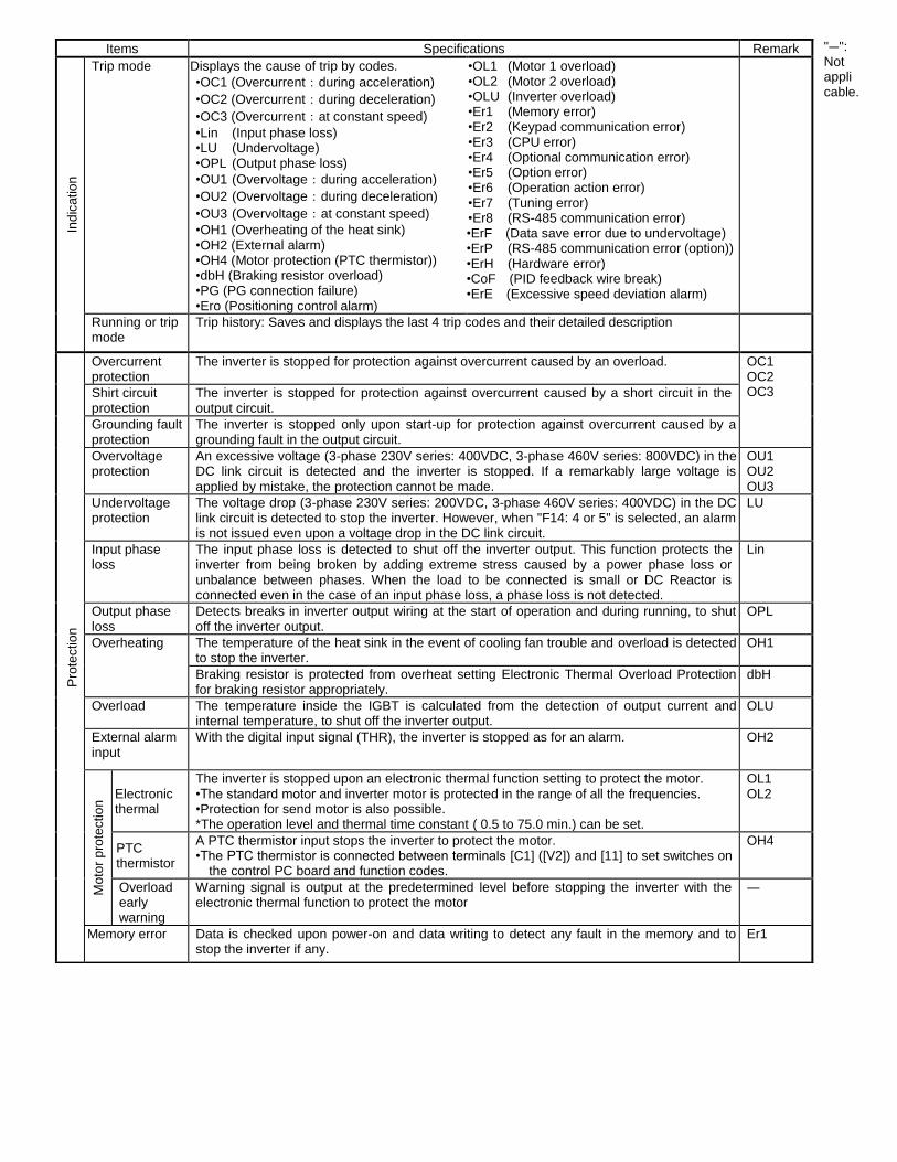
Trip mode Displays the cause of trip by codes.
•OC1 (Overcurrent:during acceleration)
•OC2 (Overcurrent:during deceleration)
•OC3 (Overcurrent:at constant speed)
•Lin (Input phase loss) •LU (Undervoltage) •OPL (Output phase loss)
•OU1 (Overvoltage:during acceleration)
•OU2 (Overvoltage:during deceleration)
•OU3 (Overvoltage:at constant speed)
•OH1 (Overheating of the heat sink) •OH2 (External alarm) •OH4 (Motor protection (PTC thermistor)) •dbH (Braking resistor overload) •PG (PG connection failure) •Ero (Positioning control alarm)
•OL1 (Motor 1 overload) •OL2 (Motor 2 overload) •OLU (Inverter overload) •Er1 (Memory error) •Er2 (Keypad communication error) •Er3 (CPU error) •Er4 (Optional communication error) •Er5 (Option error) •Er6 (Operation action error) •Er7 (Tuning error) •Er8 (RS-485 communication error) •ErF (Data save error due to undervoltage) •ErP (RS-485 communication error (option)) •ErH (Hardware error) •CoF (PID feedback wire break) •ErE (Excessive speed deviation alarm)
Running or trip mode
Trip history: Saves and displays the last 4 trip codes and their detailed description
Pro
tectio
n
Overcurrent protection
The inverter is stopped for protection against overcurrent caused by an overload. OC1 OC2 OC3 Shirt circuit
protection The inverter is stopped for protection against overcurrent caused by a short circuit in the output circuit.
Grounding fault protection
The inverter is stopped only upon start-up for protection against overcurrent caused by a grounding fault in the output circuit.
Overvoltage protection
An excessive voltage (3-phase 230V series: 400VDC, 3-phase 460V series: 800VDC) in the DC link circuit is detected and the inverter is stopped. If a remarkably large voltage is applied by mistake, the protection cannot be made.
OU1 OU2 OU3
Undervoltage protection
The voltage drop (3-phase 230V series: 200VDC, 3-phase 460V series: 400VDC) in the DC link circuit is detected to stop the inverter. However, when "F14: 4 or 5" is selected, an alarm is not issued even upon a voltage drop in the DC link circuit.
LU
Input phase loss
The input phase loss is detected to shut off the inverter output. This function protects the inverter from being broken by adding extreme stress caused by a power phase loss or unbalance between phases. When the load to be connected is small or DC Reactor is connected even in the case of an input phase loss, a phase loss is not detected.
Lin
Output phase loss
Detects breaks in inverter output wiring at the start of operation and during running, to shut off the inverter output.
OPL
Overheating The temperature of the heat sink in the event of cooling fan trouble and overload is detected to stop the inverter.
OH1
Braking resistor is protected from overheat setting Electronic Thermal Overload Protection for braking resistor appropriately.
dbH
Overload The temperature inside the IGBT is calculated from the detection of output current and internal temperature, to shut off the inverter output.
OLU
External alarm input
With the digital input signal (THR), the inverter is stopped as for an alarm. OH2
Mo
tor
pro
tectio
n Electronic
thermal
The inverter is stopped upon an electronic thermal function setting to protect the motor. •The standard motor and inverter motor is protected in the range of all the frequencies. •Protection for send motor is also possible. *The operation level and thermal time constant ( 0.5 to 75.0 min.) can be set.
OL1 OL2
PTC thermistor
A PTC thermistor input stops the inverter to protect the motor. •The PTC thermistor is connected between terminals [C1] ([V2]) and [11] to set switches on
the control PC board and function codes.
OH4
Overload early warning
Warning signal is output at the predetermined level before stopping the inverter with the electronic thermal function to protect the motor
―
Memory error Data is checked upon power-on and data writing to detect any fault in the memory and to stop the inverter if any.
Er1
Items Specifications Remark
Pro
tectio
n
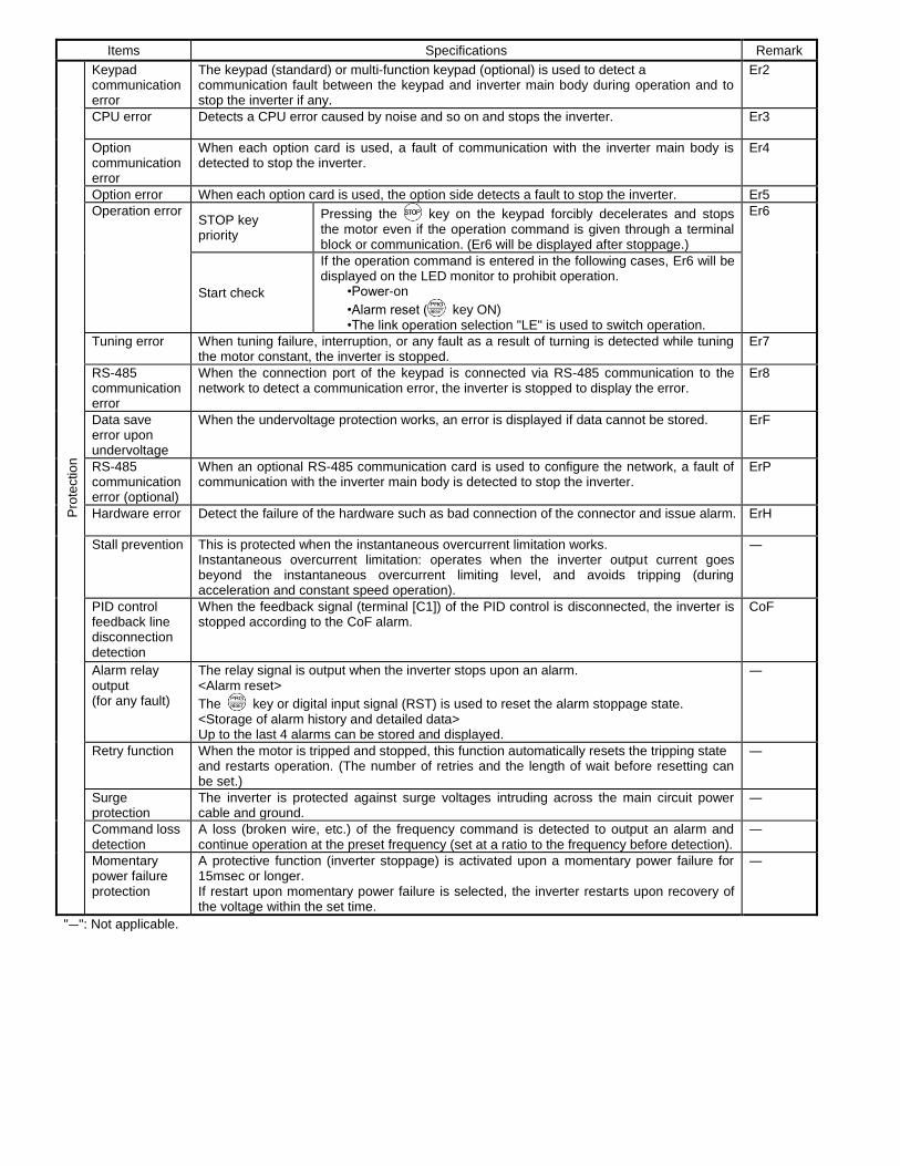
Keypad communication error
The keypad (standard) or multi-function keypad (optional) is used to detect a communication fault between the keypad and inverter main body during operation and to stop the inverter if any.
Er2
CPU error Detects a CPU error caused by noise and so on and stops the inverter. Er3
Option communication error
When each option card is used, a fault of communication with the inverter main body is detected to stop the inverter.
Er4
Option error When each option card is used, the option side detects a fault to stop the inverter. Er5
Operation error STOP key priority
Pressing the key on the keypad forcibly decelerates and stops the motor even if the operation command is given through a terminal block or communication. (Er6 will be displayed after stoppage.)
Er6
Start check
If the operation command is entered in the following cases, Er6 will be displayed on the LED monitor to prohibit operation.
•Power-on
•Alarm reset ( key ON) •The link operation selection "LE" is used to switch operation.
Tuning error When tuning failure, interruption, or any fault as a result of turning is detected while tuning the motor constant, the inverter is stopped.
Er7
RS-485 communication error
When the connection port of the keypad is connected via RS-485 communication to the network to detect a communication error, the inverter is stopped to display the error.
Er8
Data save error upon undervoltage
When the undervoltage protection works, an error is displayed if data cannot be stored. ErF
RS-485 communication error (optional)
When an optional RS-485 communication card is used to configure the network, a fault of communication with the inverter main body is detected to stop the inverter.
ErP
Hardware error Detect the failure of the hardware such as bad connection of the connector and issue alarm. ErH
Stall prevention This is protected when the instantaneous overcurrent limitation works. Instantaneous overcurrent limitation: operates when the inverter output current goes beyond the instantaneous overcurrent limiting level, and avoids tripping (during acceleration and constant speed operation).
―
PID control feedback line disconnection detection
When the feedback signal (terminal [C1]) of the PID control is disconnected, the inverter is stopped according to the CoF alarm.
CoF
Alarm relay output (for any fault)
The relay signal is output when the inverter stops upon an alarm. <Alarm reset>
The key or digital input signal (RST) is used to reset the alarm stoppage state. <Storage of alarm history and detailed data> Up to the last 4 alarms can be stored and displayed.
―
Retry function When the motor is tripped and stopped, this function automatically resets the tripping state and restarts operation. (The number of retries and the length of wait before resetting can be set.)
―
Surge protection
The inverter is protected against surge voltages intruding across the main circuit power cable and ground.
―
Command loss detection
A loss (broken wire, etc.) of the frequency command is detected to output an alarm and continue operation at the preset frequency (set at a ratio to the frequency before detection).
―
Momentary power failure protection
A protective function (inverter stoppage) is activated upon a momentary power failure for 15msec or longer. If restart upon momentary power failure is selected, the inverter restarts upon recovery of the voltage within the set time.
―
"―": Not applicable.

Items Specifications Remark
En
vir
on
me
nt
Installation location
Shall be free from corrosive gases, flammable gases, oil mist, dusts, and direct sunlight. (Pollution degree 2 (IEC60664-1)). Indoor use only.
Ambient temperature
-10 to +50°C (14 to 122°F) (-10 to 40°C (14 to 104°F) when inverters are installed side by side without clearance for 5HP or below)
Ambient humidity
5 to 95% (no condensation)
Altitude 3300ft (1000m) or less Above 3300ft (1000m) to 9800ft (3000m) or less (Output derating is necessary.)
Above 3300ft (1000m) to 4900ft (1500m) or lower :0.97
Above 4900ft (1500m) to 6600ft (2000m) or lower:0.95
Above 6600ft (2000m) to 8200ft (2500m) or lower:0.91
Above 8200ft (2500m) to 9800ft (3000m) lower:0.88
Vibration 3mm (vibration width) : 2 to less than 9Hz, 9.8m/s
2 : 9 to less than 20Hz
2m/s2 :20 to less than 55Hz
1m/s2 :55 to less than 200Hz
Storage temperature
-25 to +70°C (-13 to 158°F)
Storage temperature
5 to 95%RH (no condensation)

3. Terminal functions
Symbol Terminal name Specification Remark M
ain
circuit
L1/R, L2/S L3/T
Power input Connect a three-phase power supply. (Three-phase 230V/460V input)
L1/L, L2/N Connect a single-phase power supply. (Single-phase 230V input)
U, V, W Inverter output Connect a three-phase motor.
P(+), P1 For DC reactor Connect the DC reactor (DCR).
P(+), N(-) For DC bus connection
Used for DC bus connection.
P(+), DB For braking resistor Connect a external braking resistor
G Grounding Terminal for inverter grounding Two terminals are provided.
Fre
qu
en
cy s
ett
ing
s
[13] Potentiometer power supply
Used for frequency setting device power supply (variable resistance: 1 to 5kΩ)
+10VDC +10mADC max.
[12] Voltage input
(Inverse operation) (PID control)
(Frequency aux.
setting)
• Used as a frequency setting voltage input. -10VDC to 0VDC to +10VDC / -100% to 0 to 100%
• +10VDC to 0VDC to -10VDC / -100% to 0 to 100% • Used for setting signal (PID command value) or feedback
signal. • Used as additional auxiliary setting to various frequency
settings.
Input impedance: 22kΩ
Maximum input: +15VDC
Gain:200%
Offset:±5%
Filter:5s
[C1] Current input • Used as a frequency setting current input. +4 to +20mADC / 0 to 100%
Input impedance: 250Ω
Maximum input: +30mADC
Voltage input • Used as a frequency setting voltage input. (Changed with a switch) 0 to +10VDC / 0 to 100%
Input impedance: 22kΩ
Maximum input: +15VDC
(Inverse operation) (PID control)
(Frequency aux.
setting)
• +20 to +4mADC / 0 to 100%, +10 to 0VDC / 0 to 100% • Used for setting signal (PID command value) or feedback
signal • Used as additional auxiliary setting to various frequency
settings.
Gain:200%
Offset:±5%
Filter:5s
For PTC thermistor connection
• Connect a PTC thermistor for a motor protection. A resistor for voltage divide is equipped. (Changed with a switch)
[11] Common for analog input
Common for Frequency setting input/output signals. ([12], [13], [C1], [FMA])
Two terminals are provided. Terminal [11] is isolated from terminal [CM], [CMY].

Symbol Terminal name Specification Remark
Dig
ital in
pu
ts
[X1] Digital input 1 The following functions can be set at terminals [X1] to [X5], [FWD] and [REV] for signal input. <Common function> • Sink and source are changeable using the built-in sliding
switch. • Input logic can be changed between short-circuit of
terminals [X1] and [CM] and open circuits of them. The same setting is possible between [CM] and any of the terminals among [X2], [X3], [X4], [X5], [FWD], and [REV].
ON state Source current:
2.5 to 5mA Voltage level: 2V OFF state Allowable leakage current: Smaller than 0.5mA Voltage: 22 to 27V
[X2] Digital input 2
[X3] Digital input 3
[X4] Digital input 4
[X5] Digital input 5
[FWD] Forward operation command
[REV] Reverse operation command
(FWD) Forward operation command
The motor runs in the forward direction upon ON across (FWD) and CM. The motor decelerates and stops upon OFF.
This function can be set only for the terminals [FWD] and [REV]. Only an active ON signal is acceptable.
(REV) Reverse operation command
The motor runs in the reverse direction upon ON across (REV) and CM. The motor decelerates and stops upon OFF.
(SS1) (SS2) (SS4) (SS8)
Select Multi-frequency
16 frequencies can be selected with ON/OFF signals at (SS1) to (SS8).
(HLD) 3-wire operation stop command
Used for 3-wire operation. ON across (HLD) and [CM]: The inverter self-holds FWD or REV signal. OFF across (HLD) and [CM]: The inverter releases self-holding.
(RT1) Select ACC. / DEC. time
ACC1/DEC1 is select when (RT1) is OFF and ACC2/DEC2 is select when (RT1) is ON.
(BX) Coast to a stop The inverter output is shut off immediately and the motor coasts to a stop when (BX) is ON.
(RST) Reset alarm Faults are reset when (RST) is ON. 0.1s or more signal required.
(THR) External alarm trip The inverter output is shut off immediately and the motor coasts-to-stop when (THR) is OFF.
(Hz2/Hz1) Select frequency command 2/1
Frequency setting 2 is selected when (Hz2/Hz1) is ON.
(M2/M1) Motor2/Moor1 Motor 1 is effective when (M2/M1) is OFF and Motor 2 is effective when (M2/M1) is ON.
(DCBRK) Enable DC braking DC braking is enable when (DCBRK) is ON.
(TL2/TL1) Select torque limiter level
Torque limiter level 1 is selected when (TL2/TL1) is OFF and Torque limiter level 2 is selected when (TL2/TL1) is OFF.
(UP) UP command The output frequency increases while (UP) is ON.
(DOWN) DOWN command The output frequency decreases while (DOWN) is ON.
(WE-KP) Enable data change with keypad
Enable data change with keypad when (WE-KP) is ON.
(Hz/PID) Cancel PID control PID control is canceled when (Hz/PID) is ON. (Inverter runs with a selected frequency by Multi-frequency, Keypad, analog input, etc…)
(IVS) Switch normal/inverse operation
The frequency setting or PID control output signal (frequency setting) action mode switches between normal and inverse actions according to (IVS) ON/OFF status.
(LE) Enable communication link via RS-485 or field bus
Enable communication link via RS-485 or field bus when (LE) is ON.
(U-DI) Universal DI An arbitrary digital input signal is transmitted to the host controller.
(STM) Enable auto search for idling motor speed at starting
Enable auto search for idling motor speed at starting when (STM) is ON.
(STOP) Force to stop Inverter decelerates and stop with a deceleration time for force to stop when (STOP) is ON.
(PID-RST) Reset PID integral and differential component
Reset PID integral and differential component when (PID-RST) is ON.
(PID-HLD) Hold PID integral component
Hold PID integral component when (PID-HLD) is ON.

Symbol Terminal name Specification Remark D
igital in
pu
ts
(OLS) Enable overload
stop
Enable overload stop function when (OLS) is ON.
(JOG) Ready for jogging Operation mode is changed to Jogging mode and frequency, ACC./DEC. time are changed to those for Jogging operation when (JOG) is ON.
[PLC] PLC terminal Connect to PLC output signal power supply. Common for 24V power.
+24V(22 to 27V) 50mA max.
[CM] Common for digital inputs
Common for digital inputs [CM] is isolated from [11], [CMY]. Two terminals are provided.
Tra
nsis
tor
outp
uts
(PLC) Power supply for transistor outputs
Power supply for transistor outputs (24VDC 50mADC Max.) (This terminal is same for [PLC] terminal for digital input.)
Connect [CM] with [CMY] when this terminal is used for transistor outputs.
[Y1] Transistor outputs The following functions can be set at terminals [Y1], [Y2] for signal output. • The setting of "short circuit upon active signal output" or "open upon active signal output" is possible. • Sink/source support (switching unnecessary)
Max. voltage: 27VDC,
max. current: 50mA,
leak current: 0.1mA max.,
ON voltage: within 2V (at 50mA)
[Y2]
(RUN) Inverter running (speed exists)
An active signal is issued when the inverter runs at higher than the stop frequency.
(RUN2) Inverter output on An active signal is issued when the inverter runs at higher than stop frequency or is in DC braking.
(FAR) Frequency arrival An active signal is issued when the difference between output freq. and set freq. is equal or less than the value of function code E30 Freq. arrival (Hysteresis width).
(FDT) Frequency detected
An active signal is issued when output freq. gets equal or higher than the value specified by function code E31. The signal is deactivated if the output frequency falls below the freq. less than function data E31 minus function data E32.
(LU) Undervoltage detected
An active signal is issued when inverter dc link voltage is undervoltage detection level or below.
(B/D) Torque polarity detected
An active signal is issued when the inverter is in driving mode. This signal is inactive when the inverter is in braking mode stops.
(IOL) Inverter output limiting
An active signal is issued when the current limiting, Automatic Deceleration or torque limiting limits inverter output.
(IPF) Auto-restarting after momentary power failure
An active signal is issued until restarting is completed after momentary power failure.
(OL) Motor overload early warning
An active signal is issued when the calculated value of electronic thermal overload exceeds the preset detection level.
(RDY) Inverter ready to run
An active signal is issued when the inverter is ready to run.
(SWM2) Select Motor 2 An active signal is issued when motor 2 is selected.
(TRY) Auto-resetting An active signal is issued when the auto-resetting is in progress.
(U-DO) Universal DO Comes ON to command a peripheral apparatus according to signals sent from the host equipment.
(OH) Heat sink overheat early warning
An active signal is issued when heat sink temperature exceed warning temperature.
(FAR2) Frequency arrival signal 2
An active signal is issued when the difference between output freq. before torque limiting and the reference frequency comes to within the data of function code E29 (frequency arrival (hysteresis width)).

Symbol Terminal name Specification Remark
Tra
nsis
tor
outp
uts
(IOL2) Inverter output
limiting with delay An active signal is issued when 20ms or more elapsed after current limiting, automatic deceleration or torque limiting activates.
(ID) Current detected An active signal is issued when the output current comes to the current detection level (for ID) or above and the condition continues for the time specified current detection timer.
(LIFE) Service lifetime alarm
An active signal is issued when the service lifetime of DC link bus capacitor, capacitor on the PCBs, cooling fans have expired.
(REF OFF) Reference loss detected
An active signal is issued when reference frequency is lost.
(OLP) Overload prevention control
An active signal is issued when overload prevention function is in effective.
(ID2) Current detected 2 An active signal is issued when the output current comes to the current detection level (for ID2) or above and the condition continues for the time specified current detection timer.
(PID-ALM) PID alarm An active signal is issued when output absolute value warning or deviation warning in PID control are detected.
(THM) Motor overheat detected by thermistor (PTC)
This output signal indicates that a temperature alarm condition has been detected by a PTC (Positive Temperature Coefficient) thermistor on the motor.
(BRKS) Brake signal This signal is issued to make the mechanical brake ON/OFF.
(C1OFF) Terminal C1 off signal
Outputs ON signal when the [C1] current is smaller than 2mA.
(ALM) Alarm output (for any alarm)
An active signal is issued when the inverter is in alarm mode.
[CMY] Transistor output common
Common terminal for transistor output. [CMY] is isolated from [11], [CM].
Rela
y o
utp
ut 30A, 30B,
30C Alarm output (for any alarm)
A no-voltage contact signal (1c) is issued when the inverter is stopped due to an alarm. • Multi-purpose relay output; signals similar to above-
mentioned signals [Y1] to [Y2] can be selected. • An alarm output is issued upon either excitation or no
excitation according to selection.
Contact rating: 250VAC,0.3A,cosФ=0.3 48VDC, 0.5A
An
alo
g o
utp
ut
[FM] Analog monitor Output signal: DC voltage (0 to 10V) or Pulse frequency is selectable.
The one of the following signals can be monitored at terminal [FM].
・Output frequency 1 ( Before slip compensation )
・Output frequency 1 ( After slip compensation )
・Output current ・Output voltage ・Output torque
・Load factor ・Input power
・PID feed back value
・DC link voltage ・Universal AO
・Motor output ・Calibration analog output (+)
・PID command ・PID output
Two meters of 0 to 10VDC input impedance 22kΩ can be available for voltage output. The signal of 25 to 6000Hz can be output for pulse frequency.
Gain: 0 to 300%
Com
mun
ica
tio
ns
― RJ-45 connector for keypad connection (RS-485)
The one of the following protocol can be selectable. • Protocol for keypad (Automatically selected) • Modbus RTU • FGI bus • SX protocol for loader software
― RS-485 port (With RJ-45 connector for branch connection)
The one of the following protocol is selectable. • Modbus RTU • FGI bus OPC-E1-ETH (wired) OPC-E1-WiE (wireless) Includes
Ethernet/IP
Mobus/TCP
BACnet/IP
Profinet/IO Wireless Only
Option
4. Basic wiring diagram
L1/R
L2/S
L3/T
[13]
G
U
V
W
M3~
(Note3)
M C C Bor
G FC I
(Note2)
Three-phase200 to 240V50/60Hz
orThree-phase380 to 480V50/60Hz
Power supply
P(+)P1 N(-)
G
M ain circuit
P(+)
P1
M C
(Note1)
DCR
M otor
G rounding
G rounding
[12][11]
[C 1][11]
[FM ]
[FW D]
[C M ][REV]
[X1][X2][X3][X4][X5]
[C M ]
[PLC ]
3
2
1Voltage input0 to ±10VDC
Power supply forpotentiom eter
(Note5) C ontrol circuit
<C M Y><Y2><Y1>
(+)
(-)
C urrent/voltage input+4 to +20m ADC /0 to +10VDC
Analog input
(Note6)
Digital input
30A30B30C
30
M C C B: M olded case circuit breakerG FC I: G round-fault circuit interrupterM C : M agnetic contactorD C R: D C reactorD BR: Braking resistor
Alarm output
DB
P DB
(Note4)
DBR
[C M ]
[THR]
PTC
RS‐485 port
(option)
SINK
SO URC E
M eter
L1/L
L2/N
Single-phase200 to 240V50/60Hz
Transistor output
Analog
Pulse
4 to 20m AD C
(Note7)
0 to 10VD C
Note1:
When connecting a DC reactor (DCR) (option), remove the jumper bar from across the terminals [P1] and [P(+)]. Note2:
Install a recommended MCCB or GFCI (with an overcurrent protection function) in the primary circuit of the inverter to protect wiring. At this time, ensure that the circuit breaker capacity is equivalent to or lower than the recommended capacity.
Note3: Install a magnetic contactor (MC) recommended for each inverter to separate the inverter form the power supply, apart from the MCCB or GFCI, when necessary. Connect a surge suppressor in parallel when installing a coil such as the MC or solenoid near the inverter.
Note4:
(THR) is available when one of terminal functions for [X1] to [X5], [FWD], [REV] (function code E01 to E05、E98 orE99) is set to the
data “9”. Note5:
Frequency can be set by connecting a frequency setting device (external potentiometer) among the terminals [11], [12] and [13] instead of inputting voltage signal (0 to +10VDC, 0 to +5VDC or +1 to +5VDC) between the terminals [12] and [11].
Note6: For the control signal wires, use shielded or twisted wires. Ground shielded wires. To prevent malfunction due to noise, keep the control circuit wiring away from the main circuit wiring as far as possible (recommended: 10cm or more), and never set them in the same wire duct. When crossing the control circuit wiring with the main circuit wiring, set them at right angles.
Note 7: Three-phase 4wire cable is recommended for motor wiring to reduce the noise emitted. Connect the motor grounding wire to
the inverter grounding terminal
G.


Multi-function Keypad

NEMA 1 Models:

NEMA 1 Models:
Type Dimensions
Model W H D
FRNF12E1S-2U + NEMA1-0.2E1S-27
3.27 (83) 6.69 (170)
3.68 (93.5)
A
FRNF25E1S-2U + NEMA1-0.2E1S-27
FRNF12E1S-7U + NEMA1-0.2E1S-27
FRNF25E1S-7U + NEMA1-0.2E1S-27
FRNF50E1S-2U + NEMA1-0.4E1S-27 4.27 (108.5)
FRNF50E1S-7U + NEMA1-0.4E1S-27
FRN001E1S-2U + NEMA1-0.75E1S-2 5.26 (133.5)
FRN002E1S-2U + NEMA1-2.2E1S-24
4.45 (113) 7.15 (181.6) 5.96 (151.5) B FRN003E1S-2U + NEMA1-2.2E1S-24
FRN002E1S-4U + NEMA1-2.2E1S-24
FRN003E1S-4U + NEMA1-2.2E1S-24
FRN005E1S-2U + NEMA1-3.7E1S-24 5.63 (143) 9.91 (251.8) 6.00 (152.5) C
FRN005E1S-4U + NEMA1-3.7E1S-24
FRN003E1S-7U + NEMA1-3.7E1S-24
FRN007E1S-2U + NEMA1-7.5E1S-24
7.50 (190.6) 10.68 (271.2) 6.22 (158) D FRN010E1S-2U + NEMA1-7.5E1S-24
FRN007E1S-4U + NEMA1-7.5E1S-24
FRN010E1S-4U + NEMA1-7.5E1S-24
FRN015E1S-2U + NEMA1-15E1S-24
8.66 (220) 12.40 (315) 7.68 (195) E FRN020E1S-2U + NEMA1-15E1S-24
FRN015E1S-2U + NEMA1-15E1S-24
FRN020E1S-2U + NEMA1-15E1S-24
FRNF50E1S-4U + NEMA1-0.4E1S-4 4.45 (113) 7.09 (180)
5.01 (127.3)
A FRN001E1S-4U + NEMA1-0.75E1S-4 5.95 (151.3)
FRN001E1S-7U + NEMA1-0.75E1S-7 3.27 (83) 6.69 (170) 6.04 (153.5)
FRN002E1S-7U + NEMA1-1.5E1S-7 4.45 (113) 7.15 (181.6) 6.36 (161.5) B