general service (gs) control valves
TRANSCRIPT

GENERAL SERVICE (GS) CONTROL VALVES
GS-GENERALSERVICE VALVESThe GS-General Service Valves continues Copes-Vulcan’s tradition of designing and manufacturing control valves that provide both exceptional service and great value. Representing signifi cant refi nement in design and performance for general service globe style control valves, the GS-General Service Valves combine the most advanced levels of body confi guration, trims and actuation to produce a valve assembly capable of premium performance at a competitive price.
Suitable for controlling water, steam, gas and most other fl uids, GS-General Service Valves deliver a new standard of versatility, rugged dependability and cost eff ectiveness that will serve the power and process industries well into the 21st century.
Copes-Vulcan GS-General Service Valves are ideally suited for non-severe fl ow control of most liquids, steam and gases. They provide reliable, economical performance in heater drains, gas and fuel oil control, feedwater control, steam/gas pressure reduction and many other power and process fl ow control operations.
For applications involving extreme environments, especially hostile fl uids, or pressure classes greater than ANSI 600, specify Copes-Vulcan SD-Severe Duty Control Valves.
DESCRIPTION AND PRINCIPLE OF OPERATIONGS-General Service Valve assemblies feature a straight-through globe style body design with streamlined precision cast bodies to provide smooth contours and transition areas. The result is minimized fl ow restriction and maximized capacity. Computer calculated cross sections and wall thicknesses assure high structural integrity while maintaining a very favorable strength-to-weight ratio. The GS-General Service Valves are available in .75–8” (20–200mm) sizes as standard, ANSI pressure classes of 125–600, and most standard castable material choices, with either fl anged, welded or threaded end connections.
GS-General Service Valves can be equipped with an extensive array of standardized trims to meet virtually any general service requirement. A number of high performance trims, such as Raven, HUSH, Tandem, and GAD are also available and can be used to control occurrences of cavitation, fl ashing or noise. All trims are quick change to assure ease of maintenance. All trims are fully interchangeable between like sizes to ensure maximum fl exibility and reduced inventory requirements.
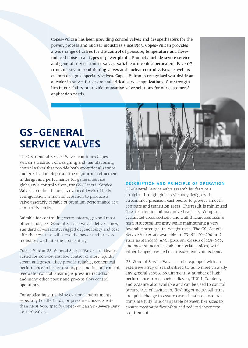
Copes-Vulcan has been providing control valves and desuperheaters for the
power, process and nuclear industries since 1903. Copes-Vulcan provides
a wide range of valves for the control of pressure, temperature and fl ow-
induced noise in all types of power plants. Products include severe service
and general service control valves, variable orifi ce desuperheaters, Raven™,
trim and steam-conditioning valves and nuclear control valves, as well as
custom designed specialty valves. Copes-Vulcan is recognized worldwide as
a leader in valves for severe and critical service applications. Our strength
lies in our ability to provide innovative valve solutions for our customers’
application needs.
Copes-Vulcan has been providing control valves and desuperheaters for the
power, process and nuclear industries since 1903. Copes-Vulcan provides
a wide range of valves for the control of pressure, temperature and fl ow-
induced noise in all types of power plants. Products include severe service
and general service control valves, variable orifi ce desuperheaters, Raven™,
trim and steam-conditioning valves and nuclear control valves, as well as
SERVICE VALVESThe GS-General Service Valves continues Copes-Vulcan’s tradition of designing and manufacturing control valves that provide both exceptional service and great value. Representing signifi cant refi nement in design and performance for general service globe style control valves, the GS-General Service Valves combine the most advanced levels of body confi guration, trims and actuation to produce a valve assembly capable of premium performance at a
Suitable for controlling water, steam, gas and most other fl uids, GS-General Service Valves deliver a new standard of versatility, rugged dependability and cost eff ectiveness that will serve the power and process industries well into the 21st century.
Copes-Vulcan GS-General Service Valves are ideally suited for non-severe fl ow control of most liquids, steam and gases. They provide reliable, economical performance in heater drains, gas and fuel oil control, feedwater control, steam/gas pressure reduction
DESCRIPTION AND PRINCIPLE OF OPERATIONGS-General Service Valve assemblies feature a straight-through globe style body design with streamlined precision cast bodies to provide smooth contours and transition areas. The result is minimized fl ow restriction and maximized capacity. Computer calculated cross sections and wall thicknesses assure high structural integrity while maintaining a very favorable strength-to-weight ratio. The GS-General
custom designed specialty valves. Copes-Vulcan is recognized worldwide as
a leader in valves for severe and critical service applications. Our strength
lies in our ability to provide innovative valve solutions for our customers’
application needs.
Copes-Vulcan GS-General Service Valves are ideally suited for non-severe fl ow control of most liquids, steam and gases. They provide reliable, economical performance in heater drains, gas and fuel oil control, feedwater control, steam/gas pressure reduction and many other power and process fl ow control
For applications involving extreme environments, especially hostile fl uids, or pressure classes greater than ANSI 600, specify Copes-Vulcan SD-Severe Duty Control Valves.
favorable strength-to-weight ratio. The GS-General Service Valves are available in .75–8” (20–200mm) sizes as standard, ANSI pressure classes of 125–600,

TYPICAL PRODUCTAPPLICATIONS
Traditional Coal-Fired Power
Heater Drain Valve
Deaerator Level Control
Aux Steam to Deaerator
Condendate Water to Condenser
Condensate Water Recycle
Cold Reheat to Aux Steam
Main Steam Letdown Spraywater
LP Feedwater Recirculation
Flash Tank Drain
Reheater Spray Control
Nuclear Power
Isolation Valves
Level Control Valves
Feedwater Valves
LP Drain Pump Recirc
Blowdown Cooling Water
Steam Transformer Blowdown
Drain Cooler to Condenser
Oil & Gas
Ethylene Control
Propane Pressure Reducing
Nitrogen to Mill Shut-O�
Gas to Burner
Oil Quick Shuto�
Heavy Oil Control
Suitable for controlling liquid, steam, gas and most other fl uids, General Service Valves deliver a new standard of versatility, rugged dependability and cost e� ectiveness.
A complete range of 700 series pneumatic diaphragm actuators that can handle supply air pressure as high as 80 psig (550 kPag) provides performance usually associated with much more expensive actuation systems. Copes-Vulcan pneumatic actuators are known worldwide for high performance and reliability.
The design is in accordance with ANSI B16.1, B16.5, B16.11, B16.25, B16.34. Copes-Vulcan also holds the following certifi cations that can be applied to the GS-Style Globe valve: ASME Section I, ASME Section III ‘N’ & ‘NPT’, 97/23/EC-PED-CE and is also ISO-9001 certifi ed.

TRIM TYPES
A broad variety of trims are available for the GS-General Service control valves. They are designed to match virtually any general service operational requirement. All GS trims feature a quick-change design to reduce downtime for inspection, maintenance or change out, and most are cage guided, further ensuring smooth, accurate operation. The entire trim line is interchangeable between like sizes, and many reduced trims are also available as standard offerings.
TRIM TYPES RAVEN™ TRIM HUSH™ TRIM SOFT SEATED HUSH™ TRIM TANDEM TRIM
DESCRIPTION/ APPLICATION
Raven is Copes-Vulcan’s top-of-the-line high performance specialty trim that offers a proven solution for those severe service applications where a true velocity control trim is the best or possibly the only answer. By limiting the fluid velocities inside the valve, Raven’s stacked disc design precludes problems typically associated with high velocity such as erosion, noise, vibration and poor control. Every Raven trim is custom designed to meet the needs of the toughest liquid, steam and gas services in the power and process industries.
HUSH Trim (multiple stage) is a high performance specialty trim that is cage guided and provides excellent control for both compressible and noncompressible fluid applications. By directing the flow through a series of staged pressure drops, this unique trim eliminates cavitation in liquid flow and provides multiple pressure breakdown for noise attenuation in critical pressure drop compressible fluid application. It is designed for all valve sizes.
Soft seated Hush Trim (double plug) is a high performance specialty trim that is cage guided and designed to provide and maintain extremely tight shutoff for high pressure differential liquid applications. Typically applied to operating conditions that exhibit pressure drops in excess of 1800 psig (12400 kPag) that are to remain closed more than 25% of the time. It is the ideal trim for applications such as boiler feed pump recirculation, spray block valves and spray control valves.
Tandem Trim is a high performance specialty trim that is a cage guided, uniquely balanced port throttling trim designed to solve difficult high temperature, high pressure differential applications that would require oversized, expensive actuators if more standard trims were utilized. Due to the relatively small pilot plug designed into the tandem trim, tight shutoff of up to Class V can easily be achieved with a moderately sized, economically priced actuator. It is available for valves 4” (100mm) and larger.
STANDARD FCI 70-2/ANSI RATED SEAT LEAKAGE
Class lV standardClass V optional
*Class VI optional
Class lV standardClass V optional
*Class VI optional Class VI standard Class IV standard
Class V optional
STANDARD TRIIM CHARACTERISTIC
Linear standard, Specials optional
Linear standard, Specials optional
Linear standard, Specials optional Special
TYPICAL FLOW DIRECTION
Under the seatOver the seat Under the seat Over the seat Over the seat
Under the seat
MAXIMUMRANGEABILITY
200:1Or greater as required 35-50:1 Under the seat 25-50:1
* Class VI requires use of soft seat.

The trims shown in this bulletin are a partial representation of the standard trim selection. Additional standard, special and custom trims are available as required. Standard stocked trim materials are 300 series and 400 series stainless steel. Other materials are available as required.
Unbalanced Single Seat Plug Throttling
Unbalanced Single Seat Port Throttling
Balanced Single Seat Port Throttling
Balanced Single Seat Port Throttling
(Hi-Temp)
* Class VI requires use of soft seat.
GAD TRIM UNBALANCED SINGLE SEAT
PLUG THROTTLINGUNBALANCED SINGLE SEAT
PORT THROTTLINGBALANCED SINGLE SEAT
PORT THROTTLING
BALANCED SINGLE SEAT PORT THROTTLING
(HI-TEMP)
GAD Trim is a high performance specialty trim that is cage guided and engineered to meet the rigorous requirements of feedwater control and feedwater startup control. Designed to give optimum flexibility in automated control valves, this trim is available in double seat, balanced single seat, tandem plug and one-stage Hush versions. GAD Trim is equally suitable for use with steam and many other fluids. It has been successfully used on high pressure water applications involving pressure of 5075 psi (34970 kPa) and pressure differential of up to 3625 psi (24980 kPa). It is available for valves 2” (50mm) and larger.
This trim style is a general purpose cage guided trim for on/off or modulating control. It is designed for low to moderate pressure drop applications. The solid plug has a contour on its lower end that provides varying flow area with lift, thus regulating the flow. It can be used with a wide variety of non-abrasive/non-adhesive compressible and noncompressible fluids. Standard trim for valve sizes 1.5” (40mm) and smaller.
This trim style is a general service cage guided trim for on/ off or modulating control where moderate flow rates exist along with low differential pressures. The unbalanced single seat plug modulates flow by uncovering ports in the cage. The cage porting produces the pressure drop or flow control. This trim can be used in most non-abrasive/non-adhesive compressible and noncompressible fluids.
This trim style is a general purpose cage guided trim for on/off or modulating control suitable for use in most non-abrasive/non-adhesive compressible and noncompressible fluid services. The balanced plug design reduces actuator force requirements thus permitting the use of smaller, less expensive actuators while maintaining tight shutoff capability. It is designed for valves 2” (50mm) and larger and is a standard offering when the service temperature does not exceed the 400°–500°F (204°– 260°C) range, relative to pressure.
This general purpose cage guided trim is virtually identical in all respects to the balanced single seat port throttling trim except that piston rings are used in lieu of the elastomeric seal on the trim’s plug. While the piston rings do limit the leakage rate to ANSI Class III, this trim is a viable option when a balanced plug is desirable and when temperatures of the fluid exceed 500°F (260°C). It is for valve sizes 2” (50mm) and larger.
Class I I I–IVDepending upondesign selected
Class IV standard Class V optional
Class IV standard Class V optional
Class IV standard Class V optional
*Class VI optionalCClass IV standard
Modif ied parabol ic ,l inear, equal percentage.All avai lable as standard
Modified parabolic,l inear, equal percent-
age.Modified parabolic, linear,
equal percentageModified parabolic, linear,
equal percentageModified parabolic, linear,
equal percentage
Over the seat Under the seat Under the seat Over the seat Over the seat
50:1 50:1 35-50:1 35-50:1 35-50:1

TRIM TYPES (CONT.)
* Class VI requires use of soft seat.
TRIM TYPES ONE STAGE HUSH CASCADE CAV B9® TOP GUIDED
DESCRIPTION/ APPLICATION
One Stage Hush trim is a specialty trim designed to reduce noise associated with compressible fluids as well as to reduce the undesirable effects of flashing and cavitation that would occur with most single pressure drop trims. The Hush cage consists of a single cylinder with a large number of radially drilled orifices. The fluid exits the orifices as low energy jets resulting in significant reductions in noise or erosion. Although numerous standard designs are available, One Stage Hush is often custom engineered to provide various flow characteristics or optimal performance under specific operating conditions.
This trim style is a cage guided plug throttling trim designed primarily for high pressure drop water applications where cavitation, vibration and excessive wear occur with conventional trims. The tapered plug fits into a cage and seat with a matching taper, thus small changes in flow area occur with respect to plug travel resulting in extremely high rangeability. The labyrinth grooves machined into the plug’s taper create a series of orifices which reduces the total pressure drop in a series of stages. It is especially suited to applications where small flow rates must be controlled accurately.
CAV B9 trim can be applied in liquid service where low level cavitation is evident. By utilizing flow over the seat, the radially step-drilled cage design reduces the effects of cavitation along with the associated noise and erosion problems by forcing the cavitation to occur in the center of the cage, away from all metal surfaces. In instances where flashing conditions are experienced, flow under the seat is employed with the multitude of small ports reduc-ing both noise and erosion. Although numerous standard designs are available, the trim can be custom designed to provide various flow characteristics or optimal performance under specific flow conditions. It is available for valves 2” (50mm) and larger.
This non-cage guided trim is designed for use with a wide variety of process applications involving corrosive, erosive and viscous line fluids and many steam and water applications. It is ideal for control applications where a maximum of free flow area is desired. The trim is unbalanced, single seat, plug throttling with the plug guided by a large diameter metal or teflon insert along the lower stem area. This guiding method ensures quiet, stable, vibration free operation with pressure drops limited to 600 psi (4130 kPa) under operating conditions. Pressure drop should also be limited to avoid cavitation or flashing. It is for valve sizes 4” (100mm) and smaller.
STANDARD FCI 70-2/ANSI RATED SEAT LEAKAGE
Class IV standard Class V optional
*Class VI optional
Class IV standard Class V optional
Class IV standard Class V optional
*Class VI optional
Class IV standard Class V optional
*Class VI optional
STANDARD TRIM CHARACTERISTIC
Linear standard Specials optional Special Linear standard
Specials optional Equal percentage, linear
TYPICAL FLOW DIRECTION
Under the seat Over the seat Under the seat
Under the seat (for flashing) Over the seat (for
cavitation)Under the seat
MAXIMUM RANGEabil ity 35-100:1 200:1 35-100:1 25:1

ACTUATORS
SERIES 700 ACTUATORSSeries 700 actuators are pneumatic diaphragm operators that have spring return in both direct and reverse acting styles, off ering fail open and fail closed models respectively. The pressed steel diaphragm case construction along with the nylon reinforced Buna-N rubber diaphragm permits a maximum allowable air supply pressure of 80 psig (550 kPag).
This pre-formed diaphragm provides a constant eff ective area throughout the full extent of travel.
With eff ective diaphragm areas ranging from 60-160 in2 (385-1030 cm2). Series 700 actuators can provide the necessary stem force to meet virtuallyany operating requirement.
P
O
L
M
An optional top mounted handwheel is available on both direct and reverse acting actuators, permitting manual operation of the valve should a loss in supply air pressure occur. Force is exerted directly on the actuator stem, making manual positioning smooth, easy and precise.
The top mounted handwheel will operate the valve in one direction. For direct acting units, the hand-wheel will extend the actuator stem; and for reverse acting units, the stem will be retracted. Side mounted handwheels are also available for Series 700 actuators. Contact Copes-Vulcan for details.
Copes-Vulcan off ers handwheel operated actuators for applications where an automated valve is not required or where compressed air service is unavailable. Series 800 actuators are suitable for both on/off and modulating service. Since they are attached to the valve bonnet and stem using the same arrangement as the Series 700, future conversion to an automated actuator can be accomplished.
SERIES 700 ACTUATOR (SHOWN WITH OPTIONAL TOP-MOUNTED HANDWHEEL)
Reverse Acting (Spring-to-Close) Direct Acting (Spring-to-Open)
InchesMillimeters
InchesMillimeters
ACTUATORSIZE 60 100 160 160L
L 21.06536
28.06713
32.38822
40.811037
M 11.50292
15.12384
18.00457
18.00 457
N 6.50165
6.50165
6.25159
6.38162
O 6.72171
11.38289
11.56294
17.19437
P 10.00254
18.00457
18.00457
18.00457
ACTUATORSIZE 60 100 160 160L
L 20.50521
28.12714
32.31821
39.751010
M 11.50292
15.12384
18.00457
18.00 457
N 7.56192
9.38238
9.31236
11.81300
O 5.81148
9.44240
9.50241
15.19386
P 10.00254
18.00457
18.00457
18.00457

Celeros Flow Technology reserves the right to incorporate our latest design and material changes without notice or obligation.Design features, materials of construction, and dimensional data, as described in this bulletin, are provided for your information only and should not be relied upon unless confi rmed in writing. Please contact your local sales representative for product availability in your region. For more information, visit www.celerosft.com.CV_415_02_GSCV_GB Version o1/2021 Issued 01/2021COPYRIGHT © 2021 CELEROS, Inc.
www.celerosft.com
GENERAL SERVICE (GS) CONTROL VALVES
P: +44 1606 552041
F: +44 1606 558275
GS Valve Body/Bonnet AssemblyFLANGED ENDS
WELD ENDS AND THREADED ENDS (FOR 2” (50MM) AND SMALLER)
VALVE SIZE
CLASS 150 CLASS 300 CLASS 400 CLASS 600
A B C A B C A B C A B C
.75”20mm
7.25184
7.00178
1.6943
7.62194
7.00178
1.6943
8.12206
7.00178
1.6943
8.12206
7.00178
1.6943
1”25mm
7.25184
7.00182
1.6943
7.75197
7.00178
1.6943
8.25210
7.00178
1.6943
8.25210
7.00178
16943
1.5”40mm
8.75222
7.15182
1.9449
9.25235
7.15182
1.9449
9.88251
7.15182
1.9449
9.88251
7.15182
1.9449
2”50mm
10.00254
7.15182
2.5064
10.50267
7.15182
2.5064
11.25286
7.15182
2.5064
11.25286
7.15182
2.5064
3”75mm
11.75298
9.47241
3.3184
12.50318
9.47241
3.3184
13.25337
9.47241
3.3184
13.25337
9.47241
3.3184
4”100mm
13.88353
10.56268
4.00102
14.50368
10.56268
4.00102
15.25387
10.56268
4.00102
15.50394
10.56268
4.0102
6”150mm
17.75451
11.81300
5.50140
18.62473
11.81300
5.50140
19.50495
11.81300
5.59142
20.00508
11.81300
5.50140
8”200mm
21.38543
13.06332
6.88175
22.38568
13.06332
6.88175
23.38594
13.06332
6.88175
24.00610
13.06332
6.88175
VALVE SIZE
CLASS 150 CLASS 300 CLASS 400 CLASS 600
A B C A B C A B C A B C
.75”20mm
7.75197
7.00178
1.6943
7.75197
7.00178
1.6943
7.75197
7.00178
1.6943
7.75197
7.00178
1.6943
1”25mm
7.75197
7.00182
1.6943
7.75197
7.00178
1.6943
7.75197
7.00178
1.6943
7.75197
7.00178
16943
1.5”40mm
9.25235
7.15182
1.9449
9.25235
7.15182
1.9449
9.25235
7.15182
1.9449
9.25235
7.15182
1.9449
2”50mm
10.50267
7.15182
2.5064
10.50267
7.15182
2.5064
10.50267
7.15182
2.5064
10.50267
7.15182
2.5064
3”75mm
12.50318
9.47241
3.3184
12.50318
9.47241
3.3184
12.50318
9.47241
3.3184
12.50318
9.47241
3.3184
4”100mm
14.50368
10.56268
4.00102
14.50368
10.56268
4.00102
14.50368
10.56268
4.00102
14.50368
10.56268
4.0102
6”150mm
20.00508
11.81300
5.50140
20.00508
11.81300
5.50140
20.00508
11.81300
5.59142
20.00508
11.81300
5.50140
8”200mm
24.00610
13.06332
6.88175
24.00610
13.06332
6.88175
24.00610
13.06332
6.88175
24.00610
13.06332
6.88175
InchesMillimeters