general reserve engineer force - border …bro.gov.in/writereaddata/tenders/5913168506.doc · web...
TRANSCRIPT

CA NO: CE(P) BCN/ / 2010-11 Ser Page No: 01Tender No: CE(P) BCN/ 49 /2009-10
BORDER ROADS ORGANISATIONHEADQUARTERS CHIEF ENGINEER PROJECT BEACON
Part _ I , (‘T’-BID UN-PRICED BID)
COMPOSITION PAGE
NAME OF WORK: CONSTRUCTION/IMPROVEMENT AND SURFACING WORK OF KISHTWAR-SINTHANPASS - ANANTNAG ROAD BETWEEN KM 46.00 TO KM 83.00 TO NHDL SPECIFICATIONS TO BE EXECUTED THROUGH CONTRACT AS TURN KEY PROJECT UNDER 35 BRTF SECTOR PROJECT BEACON IN J&K STATE.
The following shall form part of this contract agreement: -
Document annexed hereto
S/No Particulars Page No1. Composition page 01 To 01
2. Tender Forwarding letter 02 To 11
3. General condition of contracts 12 To 51
IAFW – 2249
4. Special condition 52 To 67
5. Particular specifications 68 To 169
6. Notice of tender 170 To 172
7. Amendment / errata to tender 173 To 174
8. Total number of pages for ( Q- Bid), available
separately
175 to 195
9. Relevant correspondence
10. Acceptance letter
Total - Nos
(Pages--
Standard Drawings:-25 Sheets
Sd/xxxx___________________________ SWSignature of contractor with seal For Accepting Officer

CA NO: CE(P) BCN/ / 2010-11 Ser Page No: 02Tender No: CE(P) BCN/ 49 /2009-10
Registered / ADHeadquartersChief EngineerProject BeaconC/o 56 APO
800160/28 /E8 12 May 2010
M/s ________________________________________________
___________________________________________________
___________________________________________________
CONSTRUCTION/IMPROVEMENT AND SURFACING WORK OF KISHTWAR-SINTHANPASS - ANANTNAG ROAD BETWEEN KM 46.00 TO KM 83.00 TO NHDL SPECIFICATIONS TO BE EXECUTED THROUGH CONTRACT AS TURN KEY PROJECT UNDER 35 BRTF SECTOR PROJECT BEACON IN J&K STATE.Dear Sir (s)
1. A set of tender documents containing T- Bid ( Prequalification bid) and Q - Bid ( Priced Bid) for the above work is forwarded herewith. Please note that tender will be received by the Chief Engineer (P) Beacon, C/o 56 APO upto 1200 Hrs on 18 Jun 2010. Tender received after the due date and time will not be considered. ‘T’-bid will be opened at 1205 hrs on 18 Jun 2010 by BOO.
2. Contractor should drop tender documents (both ‘T’ & ‘Q’-bids) in the tender box up to 1200 hrs on 18 Jun 2010. ‘T’-bid will be opened at 1205 Hrs on 18 Jun 2010 by BOO. The ‘Q’ – Bid in respect of ‘T’ - Bid qualified tenderer will be opened on 29 Jun 2010 at 1205 hrs by BOO. The ‘Q’-bid of unqualified ( T- Bid ) tenderer will be returned unopened to the firm.
3. Tenderers or their duly authorized representative who have submitted their tenders and who wish to be present at the time of opening of tenders may visit the office of Chief Engineer (P) Beacon C/O 56 APO at the above mentioned time.
4. Tender documents are prepared in two parts containing the following documents:-
Part –I Unpriced Bid ( Srl Pages 01 to 174 )(i) Notice Inviting Tenders(ii) Tender forwarding letters including instructions to tenderers.(iii) Eligibility criteria/ prequalification documents(iv) Tender page
(a) General condition of contract(b) Special condition of contract(c) Particular specifications.
Part – II Priced Bid ( Ser Page 175 to 195 ) ( Enclosed in separate envelope)(i) Schedule ‘A’ Notes(ii) Schedule ‘A’(iii) Schedule ‘ B,C & D.
Sd/xxxx___________________________ SWSignature of contractor with seal For Accepting Officer

Tender No: CE(P) BCN/ 49 / 2009-10 Ser Page No: 03CANO: CE(P) BCN/ / 2010-11
5. Tender documents shall be submitted in two parts and each part will be in separate sealed envelop ( supplied by the tenderer) marked Part I and marked Part II. Both the envelop containing Part I ( Unpriced Bid) and Part – II ( Priced Bid) duly sealed shall be put in large size envelop ( cloth lined outer cover to be supplied by the tenderers) This outer cover shall indicate name of work, name of bidder, last date and time of tender prominently.
6.1 EVALUATION CRITERIA AND SCORING OF SPECIFIED CRITERIA .
A) All tenderers enlisted with BRO in Class “SS” is the eligible class and shall be considered qualified for opening of ‘Q’ Bid subject to following ( these tenderer are not required to submit any documents for pre – qualification except at Srl (cc) to (ee)) ) :-
aa) Firm should not be overloaded beyond 7 times of their tendering limit.
bb) There should not be any adverse performance / remarks against contractor known in writing from any sources.
cc) Contractor enlisted with DGBR in class ‘SS’ to submit the following documents:-
i) Copy of registration letter as proof.
ii) Total work load in hand in BRO as on 01 April 2010.
iii) An affidavit duly attested from Ist class magistrate / Notary that there is no any adverse performance/ remarks against the firm in writing from any source.
Sd/xxxx___________________________ SWSignature of contractor with seal For Accepting Officer

Tender No: CE(P) BCN/ 49 / 2009-10 Ser Page No: 04CANO: CE(P) BCN/ / 2010-11B) The tenderers not registered with BRO as well as enlisted with BRO but two class below the eligible class of works shall meet the following prequalification criteria:-
S/No ELIGIBILITY CRITERIA DOCUMENTS REQUIRED TO BE SUBMITTED
1 Past Experience of completed works (a) Firm should have completed satisfactorily following works ( irrespective of locations) in last seven years with any Govt/ Govt undertaking :-Three works each costing not less than 30% of estimated cost of work. ie Rs 1780.00 lacOr
(a) (i) List of works completed in last 7 years and list of present works in progress.
(ii) Performance certificates issued by the competent authority ( not below the rank of Executive Engineer) of requisite value of works to prove eligibility criteria
Two works each costing not less than 40% of estimated cost of work. i e Rs 2373.20 lacOrOne work costing not less than 50% of estimated cost of work ie Rs 2966.50 lac(b) Similar nature of work, work consists of Fmn cutting, PMT works & surfacing works etc.
Firm should have completed satisfactorily at last one work of similar nature not less than 30% of the estimated cost of works ie Rs 1780.00 lac.
(b) Completion certificates issued by the competent authority ( not below the rank of Executive Engineer) of requisite value of works to prove eligibility criteria
2 (a) Firm should be solvent up to 20% of estimated cost of work ie Rs 1186.60 LacOrFirm should be considered financially sound for engagement up to estimated cost of work ie Rs 5933.00 lac.
(b) Firm should possess working capital not less than 5% of estimated cost of work ie Rs 296.65 lac.
(a) Firm should submit certificate from Nationalized / scheduled bank certifying that firm is solvent up to 20% of estimated cost of work ie Rs 1186.60 lac.OrFirm should submit certificate from Nationalized / Scheduled bank certifying that the firm is considered financially sound for engagement up to estimated cost of work ie Rs 5933.00 lac.
(b) Firm should submit certificate from Nationalized / Scheduled bank indicating working capital including overdraft facility shall also be considered as working capital.
3 Engineering Establishment:- (A For works with estimated cost more than 25 Crore
a) Three Graduate Engineer from a Govt recognized institute with minimum experience of 5 years.Orb) Three diploma Engineer from a Govt recognized
Affidavit shall be submitted from both firm and Engineers regarding employment of Engineers along with attested copy of Degree/ Diploma certificate and experience certificates.
Sd/xxxx___________________________ SWSignature of contractor with seal For Accepting Officer

institute with minimum experience of 8 years.
Tender No: CE(P) BCN/ 49/2009-10 Ser Page No: 05CA NO: CE(P) BCN/ / 2010-11S/No ELIGIBILITY CRITERIA DOCUMENTS REQUIRED TO BE SUBMITTED4 Minimum reserve:-
Firm should possess following minimum reserve / total of moveable or immovable property/ fixed assets ( in case of companies) ( 80% shall be in shape of moveable property)
(A) For works with estimated cost more than 25 Crore :- 80 lacs
1. Immovable property/ Moveable property shall be exclusively in the name of contractor/ company and not in the name of family members/ relatives/ others. In case of limited companies, these should also be reflected in Balance sheet.
2. Firms shall submit Affidavit for immovable property/ moveable property along with valuation report from registered valuer, incorporating following certificates in affidavit.
(i) That the immovable property is free from mortgages, hypothecation or any other disputes and encumbrances and clearly belongs to the contractor.Or
That the immovable is free from any disputes and encumbrances and clearly belongs to the contractors. The immovable property has been mortgaged / hypothecated for Rs _____ . Market value of immomable property as per valuation report No _____ given by registered valuer ______________________________ is Rs ______________________. Therefore balance market value of property ie Rs ___________ ( market value minus mortgaged value) is free from any mortgaged / hypothecation.
(ii) That the said immovable property has not been shown for seeking enlistment of a sister concern in BRO.(iii) That the said immovable property will not be sold, transferred, gifted or otherwise disposed off till satisfactory completion of work.
Sd/xxxx
___________________________ SWSignature of contractor with seal For Accepting Officer

Tender No: CE(P) BCN/ 49/2009-10 Ser Page No: 06CA NO: CE(P) BCN/ / 2010-11
S/No ELIGIBILITY CRITERIA DOCUMENTS REQUIRED TO BE SUBMITTED
5. Tools and PlantsMajor Highway Equipments
Firm shall submit affidavit for T&P own by him as required for construction of work with documentory proof of ownership in the name of contractor. Minimum T&P as under: -i) Tippers, trucks - 15 Nosii) Dozers - 05 Nosiii) Excavators (20T) – 02 Nosiv) Air Comp 250 cfm - 05 Nosv) Concrete mixer - 05 Nosvi) HMP of 20 to 30 TPH with electronic controlled panel - 01 Nosvii) Sensor paver finisher - 01 Nosviii) Vibratory road roller - 02 Nosix) Smooth wheeled rollers - 03 nos
6. There should not be any Govt dues/ recovery outstanding against the firm.
Firm shall submit affidavit in this regard duly attested by 1st class Magistrate/ Notary.
7. Litigation history
There should not be consistent history of unsuccessful or bad litigation ( Court/ arbitration cases in last 7 years.
1. Contractor shall submit affidavit indicating litigation cases ( court/ Arbitration cases) invoked in last 7 years with brief details. If nil cases, he will submit affidavit for nil cases duly attested by 1st class Magistrate/ Notary.
8. Performance
There should not be cancelled contracts due to default of contractor in last 7 years, poor/ adverse performance in past/ present contracts known to the deptt from any source. Firm should have not been blacklisted by any Govt Deptt.
1. Contractor shall submit affidavit giving information of cancelled contracts in last 7 years with brief details. If nil cases, he will submit affidavit for nil cases.2. Contractor shall submit affidavit giving information of black listing by any Govt Deptt, If nil cases, he will submit affidavit for nil cases duly attested by 1st class Magistrate/ Notary. 3. Deptt may also collect informations independently.
9. Proprietor/ partners/ directors should not be involved in any anti
Firm shall submit police verification report stating that proprietor/ partners/ directors of the firm are
Sd/xxxx___________________________ SWSignature of contractor with seal For Accepting Officer

social/ criminal activities not involved in any anti social/ criminal activities and nothing adverse is available in police records. In exceptional cases if it is not possible to submit the police verification report, firm shall submit affidavit that proprietor / partners/ directors of the firm are not involved in any anti social/ criminal activities and no criminal proceedings are pending in any court of law.
Sd/xxxx___________________________ SWSignature of contractor with seal For Accepting Officer

Tender No: CE(P) BCN/ 49/2009-10 Ser Page No: 07CA NO: CE(P) BCN/ / 2010-11
S/No ELIGIBILITY CRITERIA DOCUMENTS REQUIRED TO BE SUBMITTED
10 Available bid capacity
This will be evaluated as under:-Available Bid Capacity : 2AX N-BA. Maximum value of all executed works contracts in any one year during the last five years ( Updated at current price level by adding 5% escalation per annum)
N: Number of years prescribed for completion of work
B: value of the existing commitments of ongoing works to be completed during contract period of subject work updated at current price level by adding 5% escalation per annum.
Available Bid capacity should be more than the estimated cost of work.
For A:- Certificates from charted accountant indicating annual turnover of execution work construction in last 5 years.
For B:- Contractors shall submit detail of existing commitments of ongoing works in following format:-(a) Name of Work(b) Accepted contract amount( c) Date of acceptance of contract (d) Date of commencement of work.(e) Date of completion of work as per work order / extended date of completion of work approved by the competent authority.(f) Present progress ( along with documentary support).
Contractor shall also submit affidavit that above informations are correct.
6.2 The unenlisted t enderer or lower class registered tenderer of BRO fulfilling the criteria given in Srl No: (1) to (10) will only be considered qualified for opening of ‘Q- Bid.
6.3 However, Chief Engineer Project Beacon reserves the right to modify the above criteria due to administrative and other reasons what so ever may be and no damages on this account be entertained by department.Also not withstanding the above, the Chief Engineer Project Beacon reserves the right to accept or reject any applicant/tenderer based on previous/present performance of applicant with project or present work load in hand with applicant or for any reason without having to disclose this reason.”
6.4 Affidavit shall be submitted on non judicial papers of appropriate value duly attested by the Magistrate/ Notary Public.
The firm shall also submit following documents / details:-
(a) Constitution of firms along with copy of partnership deed ( for partnership firm), Memorandum and Articles of Association in case of limited companies.
(b) Copy of Registration Certificate of firm / company with Registrar of firms.
( c) Any other Credentials not covered above ( optional)
6.5 Please note that if any applicant submits false documents/informations, the applicant will be disqualified and also the administrative actions against the applicant as deemed fit by the accepting officer will be initiated.
Sd/xxxx___________________________ SWSignature of contractor with seal For Accepting Officer

Tender No: CE(P) BCN/ 49/2009-10 Ser Page No: 08CA NO: CE(P) BCN/ / 2010-117. The tender documents ( in full ) either duly downloaded from BRO website or issued by BRO along with various documents required to be submitted should be dropped in Tender Box kept at HQ CE(P) Beacon C/o 56 APO before the date and time fixed for receipt of tender. The tender received after due date and time shall not be considered and shall be returned to the tenderer unopened. BRO shall not be responsible for any postal or other delay and shall not take care to ensure the submission of tender at place and time fixed for receipt of tender.8. Tender shall be opened immediately after the time indicated in Para I herein before in the presence of tenderers or their authorized representative Price bid of tenderer shall be put in one envelop and sealed by the opening officer. Part I ( Unpriced bid) will be opened and evaluated as per BRO eligibility criteria/ Pre Qualification criteria given in the tender documents. Q- Bid ( Priced bid) of qualified tenderer will be opened on date and time mentioned above. However in case of delay same will be intimated. Priced bid in respect of technically disqualified tender will be returned unopened. Please note that:-
(a) The tender shall be based on details and data’s given in tender documents, Particular specifications, General Conditions of contracts, drawings, general information and lump sum contract form with schedule ‘A’ (list of works) to be priced by tenderers.
(b) The Chief Engineer Project Beacon, C/o 56 APO will be Accepting Officer here-in-after referred to as such for the purpose of this contract.
(c) The tender shall be accompanied with Earnest Money amounting to Rs. 9,00,000/-(Rupees Nine lac only ) in the form of Deposit at Call Receipt/Term Deposit Receipt/Special Term Deposit Receipt issued in favour of Chief Engineer (P) Beacon, C/o 56 APO by Scheduled Bank. Tenders not accompanied with earnest money will not considered for acceptance. The amount of this receipt should be basic amount and not their maturity value. Any deposit lying with the department in any form against any tender and/or contract shall not be considered for adjustment as the earnest money against the tender. Any tender not accompanied with any letter/communication containing any request for adjustment of any other deposit as earnest money shall be treated as non bonafide tender. If an unregistered/un-enlisted firm revokes his offer (tender) after opening of bids within the validity period of his offer, the earnest money deposited by the firms along with his tender will be forfeited. The Chief Engineer (P) Beacon, C/o 56 APO will return the Earnest Money wherever applicable to all unsuccessful tenders by endorsing an authority on the deposit receipt for its refund.
(d) The security deposit amount for this work shall be 25% more than the amount of earnest money based on the value of contract (i.e. 1.25 times of the earnest money) subject to the provision that in no case the individual Security Deposit shall exceed Rs. 1125000/- (Rupees Eleven lac twenty five thousand only).
(e) The tenderer shall be deemed to have full knowledge of all relevant drawings documents, samples, site & etc., whether he had inspected them or not.
(f) Tenderers are requested to quote rates both in figure and words in column 5 against each items of Schedule’A’ and extend the amount to column 6 of Schedule ‘A’.
(g) Any tender which stipulates any alternations to any of the conditions laid down or which proposes any other conditions of any description whatsoever is liable to be rejected.
(h) Tenderers are requested to submit their tender strictly complying with the various provisions given in the tender documents.(j) Accepting Officer reserves the right to accept the tender submitted by a Public Sector Undertaking, giving a price/purchase preference over other tender(s), which may be lower, as are admissible under the Govt. Policy. No claim for any compensation or otherwise shall be admissible from those, whose tenders may be rejected on account of the said Policy.
Sd/xxxx___________________________ SWSignature of contractor with seal For Accepting Officer

Tender No: CE(P) BCN/49 / 2009-10 Ser Page No: 09CANO: CE(P) BCN/ / 2010-11
(k) The submission of tender by a person implies that he has read this tender forwarding letter, the conditions of contract and has made himself aware of the scope and specifications of the work to be done and of the conditions and other factors, site conditions taxes & levies prevailing etc which may effect the quotation and execution of the work.
(l) Tenderer must be very careful to deliver a bonafide tender; failing which the tender will be out rightly rejected. Tenderers are, therefore, advised to ensure that their tender must satisfy each and every condition laid down in the notice.
9. Tenderer must ensue that the tender is unambiguous and is completed in all respect. Your particular attention is drawn to the following requirements, which must be compiled with :-
(a) Tender documents are to be signed, dated and witnessed at all the pages provided for the purpose. Each page and all corrections are to be initiated.
(b) All corrections should be signed or initiated. Use of correcting fluid is not allowed.
(c) Cloth lined envelope shall be used for returning the tender documents.
(d) In case you are submitting a BLANK TENDER word ‘ BLANK’ must be prominently endorsed on the envelope, the forwarding letter and general summary duly signed by the tenderer. The tender documents complete including drawing(s) are required to be returned to this office.
(e) If a tender is submitted on behalf of a firm, it may be signed either by all partners or a person holding a valid power of attorney from all the partners constituting the firm. The person signing the tender on behalf of another or on behalf of a firm shall attach with tender a proper power of attorney duly executed in his favour by such other person or by all the partners stating specifically that he has authority to bind such other person(s) or the firm as the case may be in all matters pertaining to the contract including the arbitration clause. The power of attorney shall be executed as indicated below:-
(i) In case of individual, a suitable affidavit should be submitted.(ii) In case of partnership concern, power of attorney shall be executed by all partners. (iii) In case of company, powe of attorney shall be executed in accordance with the constitution of company.
10. Attention of Tenderer is drawn to the Indian Official Secret Act – 1923 ( XIX of 1923 ) as amended upto date particularly Section 5 thereof.
11. Standing Security Bond and Security Deposit:-
a) In case of a contractor, who has executed the Standing Security Bond, but where the tendered cost of the work exceeds the financial limit of the contractor and the Accepting Officer decided to accept this tender, the contractor had to lodge Additional Security Deposit as notified by the Accepting Officer in the prescribed form within 30 days of the receipt by him of notification of acceptance of the tender, failing which this sum shall be recovered from the first RAR payment, and if the date of first RAR is prior to the period mentioned above, the same shall be recovered from such payment.
b) In case of a contractor who has not executed the Standing Security Bond, and the Accepting Officer decides to accept his tender, then contractor has to lodge Security Deposit when called upon before acceptance of his tender, which shall be in the form as
Sd/xxxx___________________________ SWSignature of contractor with seal For Accepting Officer

Tender No: CE(P) BCN/49 / 2009-10 Ser Page No: 10CANO: CE(P) BCN/ / 2010-11
directed by Accepting Officer. The Security Deposit amount will be communicated as per departmental norms but in no case the same shall be more than Rs 11,25,000.00 (Rupees Eleven lakhs twenty five thousand only).
c) The contractor may at his discretion furnish in lieu of Additional Security Deposit or Security Deposit a Bank Guarantee Bond executed by any Schedule Bank for the said amount. The term of Bank Guarantee Bond may be seen in the office of DGBR or CE (P) Beacon.
12. The Accepting Officer reserved the right to accept a tender submitted by a Public,Undertaking, giving a purchase preference over other tender(s) which may be lower as are admissible under the Government Policy. No claim for any compensation or otherwise shall be admissible to such tenders whose tenders may be rejected on account of the said policy.
13. In view of postal and other delays, it is suggested that your tender be posted sufficiently in advance of the last date fixed for receipt of tenders or sent through a special messenger, if necessary. Tender received late will not be considered. Telegraphic communications received in connection with this tender will also be not considered.
14. The tender shall remain open for acceptance for a period of One hundred twenty days (120 days) from the date of opening of Q- Bid of the tender.
15. This tender shall be signed and returned along with the tender documents and shall form part of the tender documents.IMPORTANT16. Tenderers are required to quote for complete scope of work as per Schedule ‘A’ particular specification, special conditions and other provisions of the tender documents, failing which the tender will be considered as “ non bonafide” and shall be liable for rejection. Tenderers rate shall be inclusive of all status levies duties, surcharges, taxes, octroi, 1% labour welfare cess, service tax etc and including VAT/ State sale tax, on works contract tax payable under the respective statutes pursuant to the Constitution 46 th Amendment Act 1982. Any other conditions stipulated by the tenderer regarding Sale Tax on works contract will not be considered and such tender will be liable for rejection.17. The tenderers are advised to visit the work site to acquaint themselves of working and site condition, before submitting their tender.18. On acceptance of tender, the name of authorized representative(s) of the contractors who would be responsible for taking instructions from Engineer- in – Charge or its authorized representatives shall be intimated by the contractor within 7 days of issue of Acceptance letters.
19 Tenderer who have downloaded the tender from the BRO website shall submit declaration along with tender documents that I/we have downloaded the tender from BRO website www.bro.gov.in or www.bro.nic.in and I/we have not tempered/ modified the tender from in any manner. In case if the same is found to be tempered modified in any manner, I/we understand that my/our tender will be summarily rejected and I/we are liable to be banned from doing business with BRO.
20. Instructions to Tenderers:- Sd/xxxx
___________________________ SWSignature of contractor with seal For Accepting Officer

Tender No: CE(P) BCN/49 / 2009-10 Ser Page No: 11CANO: CE(P) BCN/ / 2010-11
(a) The tenderer shall quote his rates on the Schedule „A‟ and General Summary pages only.
(b) In case the tenderer has to revise/modify the rates quoted in the Schedule „A‟ and/or General Summary, he may do so only in the Schedule „A‟/General Summary. However, he shall highlight the revision/modification made in Schedule „A‟ and/or General Summary through a forwarding letter.
(c) In case a tenderer has to revise his offer, after it is deposited in Tender Box, he maydo so on his letter head before the time fixed for opening of tenders in sealed/properly closed cover only. Any revision/modification in offer in the form of an open letter shall not be taken into account, while considering his originally quoted offer.
(d) In the even of lowest tenderer revoking his offer or revising his rates upward (whichwill be treated as revocation of offer), after opening of tenders, the earnest money deposited by him shall be forfeited. In case of BRO enlisted contractors, the amount equal to the earnest money stipulated in the Notice of tender, shall be notified to the tenderer for depositing the amount through MRO, failing which the amount shall be recovered from payment due to such Contractor or shall be adjusted from the Standing Security Deposit. In addition, such tenderer and his related firm shall not be issued the tender in second call or subsequent calls.
Encl.: Tender documents complete
Yours Faithfully,
Sd/xxxx___________________________ SWSignature of contractor with seal For Accepting Officer

Tender No: CE(P) BCN/49 / 2009-10 Ser Page No: 12-51CANO: CE(P) BCN/ / 2010-11
DGBR GENERAL CONDITIONS OF CONTRACTS(Based on IAFW – 2249)
FORMEASURMENT CONTRACTS (IAFW – 1779A)
NAME OF WORK: CONSTRUCTION/IMPROVEMENT AND SURFACING WORK OF KISHTWAR-SINTHANPASS - ANANTNAG ROAD BETWEEN KM 46.00 TO KM 83.00 TO NHDL SPECIFICATIONS TO BE EXECUTED THROUGH CONTRACT AS TURN KEY PROJECT UNDER 35 BRTF SECTOR PROJECT BEACON IN J&K STATE.
1. A copy of the GENERAL CONDITIONS OF CONTRACTS (IAFW-2249 : Print 1989) with errata 1 to 20 and Amendments Nos. 1 to 16 has been supplied to me/us and is in my/our possession. I/We have read and understood the provisions contained in the aforesaid GENERAL CONDITIONS OF CONTRACTS before submission of this tender and I/We agree that I/We shall abide by the terms and conditions thereof, as modified, if any, elsewhere in these tender documents.
2. It is hereby further agreed and declared by me/us, the GENERAL CONDITIONS OF CONTRACTS (IAFW-2249 : Print 1989) including condition 70 thereof pertaining to settlement of disputes by arbitration, containing 33 pages (Serial page No 12 to 44) with Errata 1 to 20 and Amendment No.1 to 16 containing 07 pages (serial page No 45to 51) shall form part of these tender documents.
3. Wherever the phrases Commander Works Engineer (CWE) and Garrison Engineer(GE) have been used in the General Conditions of Contract (IAFW-2249) the same areconsidered as Task Force Commander and OC Contract respectively as applicable inBorder Roads Organization.
Sd/xxxx___________________________ SWSignature of contractor with seal For Accepting Officer

Tender No: CE(P) BCN/49 / 2009-10 Ser Page No: 52CANO: CE(P) BCN/ / 2010-11
SPECIAL CONDITIONS
NAME OF WORK: CONSTRUCTION/IMPROVEMENT AND SURFACING WORK OF KISHTWAR-SINTHANPASS - ANANTNAG ROAD BETWEEN KM 46.00 TO KM 83.00 TO NHDL SPECIFICATIONS TO BE EXECUTED THROUGH CONTRACT AS TURN KEY PROJECT UNDER 35 BRTF SECTOR PROJECT BEACON IN J&K STATE.
1. The special conditions shall be read in conjunction with General Conditions of Contract IAFW – 2249 and wherever variation exist, the General Specifications shall take precedence over the aforesaid special conditions.
2. The special conditions given in succeeding paragraphs shall be read in conjunction with Schedule “A”, particular specifications and General Conditions of Contract IAFW 1779 A. In case of any discrepancies in the various provisions of the contract, the following order of precedence shall be observed: -
(a) Description given in Schedule “A”.(b) Particular Specifications.(c) Special conditions of contract.(d) General Condition of Contract IAFW 1779 A.
3. INSPECTION OF SITES The contractor is advised to inspect the site (s) of work by making prior appointment with the Chief Engineer Project Beacon, C/o 56 APO/ Commander 35 BRTF C/o 56 APO so as to acquaint himself with communication, conditions of access and all other cognate matters concerning the execution and completion of the work. The tenderer shall be deemed to have inspected the site and made himself familiar with various factors which may affect his quotation whether he actually inspects the site or not. No extra charges consequent on misunderstanding or otherwise will be allowed. Any paths, tracks, approaches etc., required for the movement of Plants, Equipment, Machines, Vehicles etc., to the work site and platform, bund etc., required for the execution of work, will be the responsibility of the contractor and rates quoted by him / her must include these aspects also, wherever, required.
4. LAND FOR OFFICES ETC. The contractor shall make his / her own arrangement for the land required for housing the staff and labour and for erection of store sheds, offices, godowns etc., required by him / her for this work. The contractor must ensure that the staff, labour, plant, equipment, machines, vehicles, stores etc., employed or collected in connection with the work, are so positioned that there is no hindrance to free flow of vehicular traffic on the roads. Suitable cautionary and warning signs boards and other measures are to be installed / provided by the contractor at his own cost for the safety of traffic.
5. WATER Contractor shall make his own arrangement for the supply of water required for this work and for the use of his / her staff / workmen at his own expenses. The contractor shall also arrange for storage and conveyance of water, if necessary, at his own cost.
6. FREE ACCESS TO SITES AND LOOKING AFTER OF WORKS The contractor shall give all responsible facilities to this department personnel for the Inspection of works, being executed under this contract. He / she shall also provide free access to the works if beings executed by this Department or other Agencies, if such works are located near the sites covered under this contract. Responsibility of all the works covered in this contract will lie with the work contractor till these works are fully completed and accordingly handed over to this department.
7. MINIMUM FARE WAGES PAYABLE TO LABOURERS
(a) The contractor shall pay wages not less than the fair wage fixed from time
Sd/xxxx___________________________ SWSignature of contractor with seal For Accepting Officer

Tender No: CE(P) BCN/49 / 2009-10 Ser Page No: 53CANO: CE(P) BCN/ / 2010-11to time by the State Government or minimum wages fixed under the Minimum Wages Act by Central Govt, which ever is higher.
(b) The contractor shall observe the Laws/Rule Regulations of Government of J&K State regarding the employment of labour, mode of payment of wages and cognate matters relating to the local conditions.
(c) In case local labourers are not available, the contractor may have to obtain written permit from appropriate authority of Govt of J&K State to import labour from out side the State.
(d) The contractor ensure compliance to all the labour wages laws and benefit rules for the labour employed by him.
8. MOVEMENT OF CONTRACTOR VEHICLE / RESOURCES However, contractor should fully satisfy himself / herself on load classification of these bridges and other crossings upto the bridge prior to passing his / her equipment, plants, machines, vehicles etc., wherever load classification of bridges / crossings are less than the loads to be crossed over by the contractor he / she will make his / her own arrangements for crossing over. If in future, lines of communications get disrupted, contractor will make his / her own arrangements to move the resources required for the execution and completion of the work, without any additional payment from the department, and no claim whatsoever on this account shall be entertained. The contractors vehicle, may required to ply in convoys as per direction given by the concerned Civil / Military authorities. No extra payment / Time will be admissible on this account.
9. SECURITY RESTRICTIONS
(a) Contractor’s attention is invited to condition of IAFW – 2249. He shall employ only Indian Nationals after verifying their antecedents and loyalty. The Contractor shall, on demand by the Engineer-in-Charge, submit list of his agents, employees and work people concerned and shall satisfy the Engineer-in-Charge as to the bonafide of such people.
(b) The contract and his workmen shall observe all the rules promulgated by the authority controlling and the area in which work is to be carried out Prohibition of smoking, lightening, fire precautions, search of persons on entry and exit, keeping to the specified routes, restricted hours of work etc. Thorough search of all persons and transport may be conducted by the departmental authorities at the site of works at time and any number of times for security reasons, permits, are to be obtained from Civil Authorities by the contractor for himself, his staff and labour. Nothing shall be paid extra on this account by this department.
(c) Necessary assistance will be extended to the contractor by the department for providing passes / permits to the contractor, his representatives and workman to enter the State.
10. TAXES The tendered price / rate shall, interalia be deemed to be inclusive of all taxes viz. Terminal taxes, Toll taxes, Octroi, 1% labour welfare cess, sales taxes, royalties, monopoly charges, VAT/ work contract tax etc. and the like levies payable under the respective existing statutes.
11. FOREIGN EXCHANGE / IMPORT LICENCE No foreign exchange and / or Import license will be arranged by the department in connection with the work under this contract.
12. CONTRACTOR’S PLANT / EQUIPMENT AT SITES
Sd/xxxx___________________________ SWSignature of contractor with seal For Accepting Officer

Tender No: CE(P) BCN/49 / 2009-10 Ser Page No: 54CANO: CE(P) BCN/ / 2010-11
(a) The contractor shall furnish to the Engineer-In-Charge a distribution return of his plant / equipment on the sites of works, stating the following particulars: -
(i) Particulars of plant / equipment i.e. make, Manufacture No., Model No., if any, Registration No. if any, Capacity, Year of Manufacture, Year of Purchase etc.
(ii) Total quantity at site of work.
(iii) Location indicating quantity at the site of work.
(b) For the purpose of this condition, plant / equipment shall include vehicles, trucks and lorries but not the workmen’s tools and / or any manually operated tools / equipment.
(c) The Engineer-In-Charge shall record the particulars supplied by the contractor as aforesaid in the works diary and send a return to OC Contract for record in his Office.
(d) The first return shall be submitted immediately after any plant or equipment is brought to the site. Thereafter every week changes in return shall be furnished in the following form-
Ser No Particulars of Plant / Eqpt
Total No at site of work
Location Remarks
Additional since ------------------------------
Reduction -----------------------------(Signature of contractor)
--------------------------------------------------------------------------------------------------------------------(e) A complete return showing the upto date position of plant / equipment at site shall be submitted on 15th of every month till the works are completed and the site cleared.
(f) The contractors attention is invited to condition 34 of DGBR General Conditions of contracts according to which no tool, plant /equipment shall be removed off the site without written approval of the OC contract.
13. LOSS OR DAMAGE ON ACCOUNT OF ENEMY ACTION
(a) If as a result of enemy action, the contractor suffers any loss or damage, the government shall reimburse to the contractor such loss or damages, to the extent and in the manner herein after provided: -
(i) The loss suffered by him on account of any damage or destruction of his plant / equipment (as defined in condition 11 (b) above) or materials or any part or parts thereof. The amount of losses assessed by the Accepting Officer of the contract on this account shall be final and binding.
(ii) Compensation paid by him under any law for the time being in force to any workmen employed by him for any injury caused to him or the workmen’s legal successor for loss of the workmen’s life.
(b) No requirement shall be made nor shall any compensation be payable under the above provisions unless the contractor had taken Air Defence Precautions ordered in writing by OC concerned
Sd/xxxx___________________________ SWSignature of contractor with seal For Accepting Officer

Tender No: CE(P) BCN/49 / 2009-10 Ser Page No: 55CANO: CE(P) BCN/ / 2010-11
or in the absence of such orders, reasonable precautions. No re-imbursement shall be made nor shall any compensation be payable for any plant / Eqpts or materials not lying on the site of work at the time of enemy action.
14. TIME AND PROGRESS CHART (a) The time and progress chart to be prepared as per general Condition of Contract shall
consist of detailed net work analysis and a time schedule. The critical path net work will be drawn jointly by the OC Contract and the contractor soon after acceptance of the tender. The time scheduling of the activities including a net work for all preliminary arrangements for mobilisation of resources e.g. Man power, Plant and Machinery will be done by the contractor, completion of the time schedule will be prepared and submitted by the contractor to OC Contract who will approve it after due scrutiny. The schedule will be submitted in quadruplicate within one week from the date of handing over the site.
(b) During the currency of work the contractor is excepted to adhere to the time schedule and this adherence will be part of the contractor’s performance under the contract. During the execution of the work the contractor is expected to participate in the review and updating of the net work undertaken by OC contract. These reviews may be undertaken at the discretion of the OC contract either as periodic appraisal measure or when the quantum of work ordered on the contractor is substantially changed through deviation orders or amendments. Any revision of the Schedule as a result of the review will be submitted by the contractor to the OC contract within a week, who will approved it after scrutiny. The contractor will adhere to the revised schedule thereafter. In case of the contractor’s not agreeing to the revised schedule the same will be referred to the Accepting Officer whose decision will be final, conclusive and binding. OCs approval to the revised schedule resulting in a completion date beyond the stipulated date(s) of completion shall not automatically amount to grant of extension of time. Extension of time shall be considered and decided by the appropriate authority mentioned in condition 11 of General Conditions for contracts and separately regulated.
(c) The contractor is expected to mobilise and employ sufficient resources to achieve the detailed time schedule within the broad framework of the accepted methods working and safety.
d) No additional payments will be made to the contractor for any multiple shift work or other incentive methods contemplated by him in his work schedule even though the department approves the time schedule.
15. PERMIT FROM LOCAL AUTHORITIES FOR PLYING VEHICLES Contractor shall make his own arrangements for obtaining necessary permit from local authorities for plying his vehicles for the work in accordance with the Rules and Regulations of the land.
16. REGISTRATION FEE/ TRADE TAX/ INCOME TAX ETC. Tendered rates / amount shall also be deemed to include the payment of all taxes to be like Registration fee. Trade Tax. Income-tax and other taxes / levies to be paid to the Govt. of Jammu & Kashmir or Central Govt. already in force and as may be modified from time to time. The contractor may ascertain full details on this respect from the concerned department (s).
17. ELECTRICITY The Department will supply no electricity. The contractor shall make his own arrangement for necessary power, if required.
18. ADJUSTMENT OF TAX CONSEQUENT UPON AMENDMENT TO CONSTITUTION The tendered rate shall also be inclusive of all statute levies and State / Union territory /sale tax / work contract
Sd/xxxx___________________________ SWSignature of contractor with seal For Accepting Officer

Tender No: CE(P) BCN/49 / 2009-10 Ser Page No: 56CANO: CE(P) BCN/ / 2010-11
tax on works contract payable under the respective statutes pursuant to the constitution stipulated by the tenderers regarding sales tax on works contracts will not be considered and such tender will be liable for rejection.
19. RATE QUOTED
(a) Unit rates shall be deemed to include the provisions for all materials, stores, labour, process, operations and requirements detailed in particular specifications irrespective of whether these appear as specific items or not in the Schedule 'A.
(b) Unit rate quoted shall also deemed to include all charges/expenses on account of Formation work which includes earth work in cutting, earth work in embankment by cutting and filling, earth work in embankment by filling, permanent work which includes construction of culverts like Single Row Hume Pipe culvert, Double Row Hume Pipe culvert, Reinforced cement concreteculverts of various span and pavement work which includes, preparation, laying and compacting/rolling of sub-grade for laying sub-base course, wearing coat etc. with Rollers and all other veh/eqpts required for completing the work all the as specified in Schedule „A‟ and Particular Specifications and the MORST&H Specification for Road and Bridge Work (latest revision). The rate also includes the charges for deploying of veh/eqpts/plants for above purpose, cost of stores being incorporated, sales tax, octroi, royalty charge, 1% labour welfare cess, stacking of materials at site, inter-State barrier charges and or any other taxes as applicable in accordance of the Rules of the land.
(c) The rate quoted shall also include transportation of materials required for completing the work including loading/unloading charges.
20. MEASUREMENTS
(a) For formation work the Engineer in Charge/ OC contract and the contractor or the Rep ie Engineer of the contractor will carry out the ground survey with Total station before execution the formation work for initial levels and the readings jointly recorded in the leveling field book and accordingly L-Sec and X-section of existing ground profile will be prepared and kept in record by the contractor and OC contract duly countersigned by the commander contract. When the formation work completed or formation work measured for making payment to contractor the quantities of work will be determined by taking the ground levels with Total station and L-section / X- section of work will be prepared by considering the original L- section and X-section of work. The measurements shall be recorded in cubic meters or as given in the Schedule ‘A’ for permanent work as well as for surfacing works (compacted for all items, measured as finished work at a specified thickness as detailed on the contract drawings or documents or as directed by Engr- in - charge/ OC contract.
(b) All measurements for bituminous hot mix supplied, laid, compacted and finished complete as specified shall be recorded in measurement book. No payment shall be made for the rejected material at any stage and cost of transportation, laying and compaction as a result of rejection. Rejected materials are to be removed from site by contractor at his own cost and arrangement. The contractor or his authorized representative will endorse under his signature at the end of the series of measurements taken on a particular day the words ‘MEASUREMENT ACCEPTED’. In case the
Sd/xxxx___________________________ SWSignature of contractor with seal For Accepting Officer

Tender No: CE(P) BCN/49 / 2009-10 Ser Page No: 57CANO: CE(P) BCN/ / 2010-11
contractor or his representative fails to attend for taking measurements at time and place fixed by the Engineer-in-Charge in writing, the authorized representative of Department shall take measurements himself, which shall be final and binding on the contractor.
21. ACCEPTANCE OF WORK DONE The Engineer-in-Charge/ OC contract shall exercise control over the quality of materials and work done by carrying out tests for the specified properties as per frequencies given in particular specifications.
22. Blank
23. INCOME TAX Income Tax along with education cess, 1% labour welfare cess and service/works contract tax will be deducted at source as applicable.
24. ROYALTIES
24.1. No quarries on charge of department are available. Thecontractor shall make his own arrangement for obtaining land for quarrying sand/stonesand obtaining other materials required for the work. Payment of royalties of eachmaterials shall borne by the contractors, and his quoted rates shall be deemed toinclude for the same. The contractor shall submit a royalty clearance certificates (as perproforma given at Para 24.2 here in after) issued by the department of ForestsMinerals, Govt of Arunachal Pradesh alongwith RAR(s)/Final bill failing which the saidamount of royalty shall be deducted from their RAR(s)/Final bill and shall be depositedwith State Govt.
24.2. The contractor shall submit a certificate as under: -
CERTIFICATE
It is certified that I/we, M/s (Primary License Holder) _____________________ having a License No _________________ issued by Forest/Mining Deptt, Govt. of ____________________________________ have supplied the following materials to M/s ______________________________ against CA No CE (P) BCN/____/2009-10 to Chief Engineer Project Beacon, TF Commander 35 BRTF during the period from ____________________ to_______________________________.
Ser No Materials Quantity Supplied
(a)(b)
It is further certified that royalty etc for above quantity of materials, at applicable rates have been paid by us to concerned Deptt of the Govt. of _____________. A copy of no demand certificate/Challan/Permit/Affidavit duly verified by the concerned Deptt etc is attached herewith.
(M/s ________________________(Primary License Holder)
“The payment of bill will be made only on producing the proof of payment towards royalty to the concerned authorities”.
Sd/xxxx___________________________ SWSignature of contractor with seal For Accepting Officer

Tender No: CE(P) BCN/49 / 2009-10 Ser Page No: 58CANO: CE(P) BCN/ / 2010-11
In case of any dispute between the OC contract and the contractor in this regard decision of Commander 35 BRTF shall be final and binding on both the parties.
25. REGISTRATION Contractor is required to get his firm registered with Sales Tax Department. A copy of valid registration certificate issued by the Sales Tax Department will be forwarded to Chief Engineer Project Beacon.
26. MAINTENANCE PERIOD Defect Notification Period of work shall be (12) Twelve calendar months after completion of work. 2.5% amount of the contract i.e 50 % of retention money will be kept as Special Security Deposit and same will be released after completion of maintenance period. On receipt of No Demand and No Claim Certificate from the contractor. The Bank Guarantee Bond shall be acceptable against Special Security Deposit which shall be in favour of Accepting Officer.
27. REGISTRATION FOR TRADE TAX, INCOME TAX ETC : Tendered item rates shall also be deemed to include payment of all taxes like Registration fee, Trade Tax, Income Tax ,Service Tax, 1% labour welfare cess and other taxes / levies to be paid to the State Government or Central Government already in force and as may be modified from time to time. The contractor may ascertain full details in this respect from the concerned department(s).
28 Completion Drawings: The contractor shall submit completion drawings to the OC Contract within one month of actual completion, but before final payment. 03 Nos complete set of all drawings duly binded shall be submitted to OC Contract alongwith final bill.
29. Appointment of Arbitrator ( Applicable only for contract agreement to be executed between BRO and a Public Enterprises :
In the event of any dispute or difference between the parties hereto, such dispute or differences shall be resolved amicably by mutual consultation or through the good offices of empowered agencies of the Government. In the event of any such dispute or differences relating to the interpretation and application of the provisions of contracts where such resolution is not possible then the un-resolved dispute or differences shall be referred by either party to the Arbitration of one of the Arbitrators in the department of Public Enterprises to be nominated by the Secretary to the Government of India in-charge of the Bureau of Public Enterprises and in such case the Arbitration and Conciliation Act 1996 shall not be applicable to the arbitration under this clause. The award of the Arbitrator shall be bindings upon both the parties to the dispute. Provided, however, any party, aggrieved by such award, may make a further reference for setting aside or revision of the award to the Law Secretary, department of Legal Affairs, Ministry of Law and Justice, Government of India, upon such reference the dispute shall be decided, the Law Secretary or the special Secretary/additional Secretary when so authorized by the Law Secretary, whose decision shall bind the parties conclusively. The parties to the dispute will share equally; the cost of arbitration proceedings as intimated by the Arbitrator.
30. SECURITY OF CLASSIFIED DOCUMENTS :
The contractor shall not communicate any classified information regarding works either to sub-contractors or others without prior approval of Engineer-in-Charge. The contractor shall also not make copies of the design/drawings and other documents furnished to him in respect of works and he shall return all documents on completion of the works or whenever ordered to do so. The contractor shall along with final bill attach a receipt from the Engineer-in-Charge in respect of his having returned the classified documents.
Sd/xxxx___________________________ SWSignature of contractor with seal For Accepting Officer

Tender No: CE(P) BCN/49 / 2009-10 Ser Page No: 59CANO: CE(P) BCN/ / 2010-11
31. RECORD OF CONSUMPTION OF CEMENT ,STEEL, BITUMEN AND EXPLOSIVE:
(a) (i) For the purpose of keeping a record of Major Constr Stores like Steel, Cement, Bitumen and LDO consumed in works, the contractor shallmaintain a pucca bound register in the form approved by the Engineer-in-Charge/OC Contract showing daily quantity used in works. The register shallbe signed daily by the contractor's representative and the Engineer-in-Charge/OC Contract in token of their verification of its correctness. The checkwill not, however, absolve the contractor of his responsibility to justify theconsumption of bitumen and LDO at the time of finalization of his work.
(ii) The register shall be kept at site in the safe custody of the contractor during progress of the work and shall, on demand , be produced for verification of inspecting officers.
(b) (i) The quantity of materials such as paints, water proofing compound andthe like, as directed by the Engineer-in-Charge (the quantity of which cannot bechecked after incorporation in the works), shall be recorded in measurementbooks and signed by the contractor and the Engineer-in-Charge as a check toensure that the required quantity has been brought to site for incorporation in thework.
(ii) Materials brought to site shall be stored as directed by the Engineer-in-Charge in Measurement Book and shall be suitably marked for identification.
(iii) The contractor shall, on demand produce the OC original receipted vouchers in respect of the supplies, Vouchers so produced and verified shall bestamped by Engineer-in-Charge indicating contract number. The contractor shallensurethat the materials are broughtto site in original sealedcontainers/packing, bearing manufacturer's marking except in the case of the requirement of materials(s) bring less than smallest packing.
(iv) Contractor shall produce original vouchers from the manufactures and/ or their authorized agents for the full quantity of the following materials, as applicable as a prerequisite before submitting for payment for any advances on account of the work done and/or materials collected in accordance with condition 64 of General Condition of Contracts IAFW-2249.
(a) Cement.(b) Steel items.(c) Bitumen.(d) Paint.(e) LDO
Sd/xxxx___________________________ SWSignature of contractor with seal For Accepting Officer

Tender No: CE(P) BCN/49 / 2009-10 Ser Page No:60CANO: CE(P) BCN/ / 2010-11
32. Following details shall be furnished by the contractor to OC Contract :
(a) Bank A/C No
(b) Banker’s Name and address
(c) Permanent address
33.Retrieved Material : Hard rock encountered during the formation cutting andexcavation shall become property of the contractor. Thirty three percent of Hard rock cutting as referred here above and fifty percent quantity in respect of permanent structures shall be considered as retrieved material and stacked neatly on specified ground as directed by Engineer-In-Charge/OC Contract and no extra payment shall be made on this account. Tested quality of retrieved material shall be incorporated in the work and credit on this account @ Rs100/-(Rupees One hundred only) per Cubic Mtr shall be deducted from the bills ofthecontractor. In no case credit for retrieved material shall be less than Thirty three percent.However if quantity of retrieved material is more than Thirty three percent, that shall be the property of the department..34. Disposal of Surplus Excavated Material: Forest authority has approved the mucking site for disposing off muck/unserviceable material between Km 46.00 to Km 83.00 on road Kishtwar – Sinthanpass- Anantnag. All excavated surplus material to be disposed off at ibid location as per direction of Engr – in – charge/ OC contract.
35 RECOVERY ON VARIATION OF PRICES: ISSUED AS SCH ‘B’ STORE; During the extended period, the cost of various item issued under Sch ‘B’ will be increased by 10 % every year of the rate as mentioned in Sch ‘B’ and will be recovered from contractor accordingly. Year will be effected immediately after the completion date as mentioned in WO No 1.
36. FIXING OF PERMANENT AND TEMPORARY BENCH MARKS: Pmt BenchMark be fixed at any nearby safe location or considered from any existingPermanent Building. RL be transferred and TBM be fixed at an interval of appx 200mtr along the existing alignment at safe place. There temp Bench Mark shouldremain intact till completion of the work.
37. Total Station Eqpt : The total station eqpt with its accessories be provided by the contractor and will remain at site till completion of job.
38 Payment of Work
38.1 The payment will be released through E-Payment mode, for which the contractor is required to submit the NEFT/RTGS Mandate Form (enclosed at Appx ‘B’) duly filled in the specified details. Otherwise, it will be released through A/c Payee Cheque.38.2 In case where the payment is released through cheque it will be sent by post to the Contractor for which the postage charges will be deducted from the net amount due to the Contractor.
Sd/xxxx___________________________ SWSignature of contractor with seal For Accepting Officer

Tender No: CE(P) BCN/49 / 2009-10 Ser Page No:61CANO: CE(P) BCN/ / 2010-11
39 F IELD LABORATORY : To maintain proper quality control at site, contractor to establish and adequately eqpt field laboratory without any extra cost. The field laboratory be manned by qualified technician/ Engineer.
40. SUPPLY OF COLOUR RECORD PHOTOGRAPHS, ALBUMS AND VIDEO CASSETTES : Contractor shall provide/supply of colour record photographs, Album and video cassettes at various stages/facts of the work without any extra cost as per clause 125.1, 125.2 & 126.1 of MORST&H specification (Fourth revision, reprint Nov 2008).
40. DRAWING : Drawing for each structure as per ground condition will be provided by OC Contract to execute work at the time of execution. Contractor to execute work as per drawing provided by OC Contract. Drawings however provided with tender document are for rough guidelines only.
41.BLASTING ROCKS
(a) The contractor shall be responsible for the safe custody and storage of blasting materials in accordance with the rules on the subject. Written authority of the OC shall be obtained before any blasting operations are commenced.
(b) The contractor shall ensure that the charges in blasting are not excessive and that the charged bore holes are properly protected before firing and that proper precautions are taken for the safety of men and property.
(c) Blasting should be generally avoided. In case it is unavoidable less charge controlled blasting may be resorted with the prior permission of the Engineer-in-Charge. The contractor shall be bound to abide by the instructions of the OC regarding the necessity of blasting and the type, number size and pattern of holes to be drilled and also the type, amount and method of firing of explosive to be used. The OC shall reserve the right to restrict the number of charge to be fired at a time so that the hillside is not adversely affected. The contractor shall fire the charges only at such time as approved by the OC and shall have no claim, whatsoever, on account of any delay and extra cost due to carrying out the instructions of the OC and/or taking the safety precautions directed by him.
42. FOSSILS :
42.1 All fossils, coins, articles of value or antiquity, and structures and other remains or items of geological or archaeological interest found on the Site shall be placed under the care and authority of the Employer. The contractor shall take reasonable precautions to prevent Contractor's Personnel or other persons from removing or damaging any of these findings.
42.2 The Contractor shall, upon discovery of any such findings, promptly give notice to the Engineer-in-Charge/OC Contract, who shall issue instructions for dealing with it. If the Contractor suffers delay and/or incurs Cost from complying with the instructions, the Contractor shall give a further notice the Engineer-in-Charge/OC Contract describing in detail the delay sustained by him and cost measured by him for following the instructions of the Engineer-in-Charge/OC Contract in dealing with the fossils along with all supporting documents/proof, within 7 days of the occurrence. The Contractor then be certified for the following :-
Sd/xxxx___________________________ SWSignature of contractor with seal For Accepting Officer

Tender No: CE(P) BCN/49 / 2009-10 Ser Page No:62CANO: CE(P) BCN/ / 2010-11
(a) an extension of time for any such delay, if completion is or will be delayed due to such act in following the instructions of the Engineer-in-Charge/OC Contract.
(b) payment of any such Cost, which shall be included in the Contract Price.
42.3 After receiving this further notice, the Engineer-in-Charge/OC Contract shall examine the case with facts and figures and disagreements if any will be communicated to the contractor.
42.4 In case of any disputes, the matter shall be referred to the Accepting Officer whose decision shall be final and binding.
43 TRAFFIC MOVEMENT : Contractor shall ensure that no hindrance to traffic movement shall occur during construction. However, if the traffic movement disrupt due to land slide or any other un-foreseen reason, than contractor shall make all efforts to restore traffic movement within four hours. Contractor shall immediately intimate regarding closure of the road to Engineer-In-Charge and local administrative authorities.
44. SECURITY COVER : The work is situated in Kashmir valley, therefore it is deemed that contractor is fully aware with the prevailing situation at site and any kind of Militant/Terrorist activities effecting functioning of hired machineries and or causing any loss to the men and machineries deployed is at the sole risk and responsibility of contractor.
45. INSURANCE COVER : Any kind of loss of Men / machineries in any form like accident, natural calamities, theft, militant activities is the sole responsibility contractor. Hence the contractor to make necessary insurance cover to men and machineries within his quoted rates.
46.SPECIFICATION FOR ROAD WORKS :- The MORT&H manual for specifications for road & bridge work ( 4th revision) including all codes mentioned in the manual, DGBR SSR 2004, DGBR SSR 2009 and BR Regulations are the part of this tender documents.
47 RE-IMBURSEMENT/REFUND ON VARIATION IN TAXES DIRECTLY RELATED TO CONTRACT VALUE
(a) The rates quoted by the contractor shall be deemed to be inclusive of all taxes ( including sales tax/ VAT on material, sales tax/ VAT on work contracts, Turnover tax, service tax, labour welfare cess/ tax etc), duties, royalties, Octroi & other levies payable under the respective status. No reimbursement/ re/refund for variation in rates of taxes, duties, royalties, octroi & other levies and/ or imposition/ abolition of any new/ existing taxes, duties, Royalties, Octroi & other levies shall be made except as provided in sub Para (b) here in below.
(b) (i) The taxes which are levied by the Govt at certain percentage rates of contract sum/ amount shall be termed as “ taxes directly related to contract value such as sales tax / VAT on work contracts, Turnover tax, labour welfare cess/ tax and like but excluding income tax. The tendered rates shall be deemed to be inclusive of all “ taxes directly related to contract value “ with existing percentage rates as prevailing on last due date for receipt of tenders. Any increase in percentage rates of “ taxes directly related to contract value” with reference to prevailing rates on last due date for receipt of tenders shall be reimbursed to the contractor and any decrease in percentage rates of “
Tender No: CE(P) BCN/49 / 2009-10 Ser Page No: 63
Sd/xxxx___________________________ SWSignature of contractor with seal For Accepting Officer

CANO: CE(P) BCN/ / 2010-11
taxes directly related to contract value with reference to prevailing rates on last due date for receipt of tenders shall be refunded by the contractor to the Govt/ deducted by the Govt from any payments due to the contractor. Similarly imposition of any new “taxes directly related to contract value” after the last due date for receipt of tenders shall be reimbursed to the contractor and abolition of any “ taxes directly related to contract value prevailing on last due date for receipt of tenders shall be refunded by the contractor to the Govt/ deducted by the Govt from any payments due to the contractor.
(ii) The contractor shall within a reasonable time of his becoming aware of variation in percentage rates and / or imposition of any “taxes” directly related to contract value give written notice thereof to the OC contract stating that the same is given pursuant to this special condition together ith all informations relating there to which he may be in a position to supply. The contractor shall submit the other documentary proof/ informations as the OC Contract may require.
(iii) The contractor shall, for the purpose of this condition keeps such books of account and other documents as are necessary and shall allow inspection of the same by a duly authorized representative of Govt., and shall further, at the request of the OC contract furnish, verified in such a manner as the OC contract may require, any documents so kept and such other information as the OC contract may require.
(iv) Reimbursement for increase in percentage rates/ imposition of “taxes directly related to contract value” shall be made only if the contractor necessarily & properly pays additional “ taxes directly related to contract value” to the Govt. without getting the same adjusted, against any other tax liability or without getting the same refunded from the concerned Govt. Authority and submit documentary proof for the same as the OC contract may require.”
48 LEGAL JURISDICTION Legal jurisdiction for this Contract Agreement shall be “SRINAGAR COURT”
Sd/xxxx___________________________ SWSignature of contractor with seal For Accepting Officer

Tender No: CE(P) BCN/49 / 2009-10 Ser Page No: 64CANO: CE(P) BCN/ / 2010-11
49. REIMBURSEMENT/REFUND ON VARIATION IN PRICES-WAGES OFLABOUR
Increase or decrease in prices consequent on variation in wages of labour shall be adjusted on the basis stipulated hereinafter irrespective of the actual variation in price wages of labour to the contractor :-
LABOURThe labour component for the work under the contract as a whole shall be
taken as KL of the value of the work executed under the contract. Variation in labour wages shall be worked out by adopting the following formula :-
EL = KL x Vg1 x (L 1 – LO )100 L0
Where –EL = Variation in wages of labour re-imbursement to be made to the
contractor or refund to be made by the contractor. KL = Constant representing the percentage cost of labour
element as compared to the total value of the work under the contract as a whole. The value of KL for the work shall be 20 (TWENTY).
Vg1 = Gross value of work done at contract rates during the period of reckoning less value of work paid or payable to the contractor based on actual cost (e.g. star rate(s), work executed under prime cost sum etc) during the period of reckoning.
L1 = Minimum wages in rupees of an unskilled adult male mazdoor As fixed under Minimum Wages Act, as on the date of commencement of the period of reckoning.
LO = As for L1 but the minimum wages as fixed under Minimum Wages Act in rupees of an unskilled adult male mazdoor as on the actual date of opening of price Bid (Part „Q‟) of tender.
Notes:1. The contractor shall within reasonable time of his becoming aware of any alteration to the rate of wages of labour consequent on fixation of minimum wages under Minimum Wages Act, give written notice thereof to the OC Contract stating that the same is given pursuant to this special condition together with all information relating thereto which he may be in a position to supply.2. Irrespective of the variations in minimum/fair wages for any category
Sd/xxxx___________________________ SWSignature of contractor with seal For Accepting Officer

of labour; for the purpose of adjustment under this special condition, the variation in minimum Tender No: CE(P) BCN/49 / 2009-10 Ser Page No: 65CANO: CE(P) BCN/ / 2010-11
wages fixed under Minimum Wages Act, for an unskilled adult mazdoor, if any, shall only form the basis.3. Periodicity of working out the variation in wages of labour will be three months commencing from the actual date of opening of Price Bid of tender, the last adjustment for variation in wages of labour shall, however, be done for the period upto the stipulated date of completion given in the first work order, or extended date of completion. Valuation of price adjustment due to increase/decrease in minimum wages under Minimum Wages Act, for the purpose of making reimbursement /refund in RARs, will be timed in such a manner that relevant data required for quarterly calculation under this special condition is available from the RARs. The first price adjustment in respect of variation in wages of labour will be worked out for the relevant quarter during which the variation took place. For implementing this provision, the period of reckoning in such quarter will be divided into two period, i.e. the first period upto the RAR payable immediately after the date of variation and the other upto the end of the quarter. Value of L1 at the beginning of the other period shall be altered minimum wage. If there are more than one change(s) in wages in a quarter, there will be more than two periods of reckoning on similar basis. Amount payable relevant to work done for any quarter will be worked out after the minimum wages of an unskilled adult male mazdoor as fixed under Minimum Wages Act for the relevant quarter is available. Once the amount adjustable for any quarter is worked out, the same shall be adjusted in subsequent RAR as “advance on account” adjustments.4. No adjustments in prices shall be made for any work done after the stipulated date of completion given in the first work order or extension of time granted under condition 11 of IAFW-2249 (whichever is later) for the work under this contract.5. No adjustment, whatsoever, due to variation in wages of Labour on account of coming into force of any fresh law or statutory rule or order as provided in Condition 63 of IAFW-2249 or otherwise, than provided in this special condition shall be made. In short once this special condition is operative condition 63 of IAFW-2249 stands superseded.6. Any dispute arising out of interpretation of application of this special condition shall be referred to the Accepting Officer whose decision shall be final and binding.
50. RE - IMBURSEMENT / REFUND ON VARIATION IN PRICES : MATERIALS & FUEL ( THIS SUPERSEDES CONDITION 63 OF IAFW -2249)Increase or decrease in prices of materials and fuel shall be adjusted on the basis stipulated hereinafter irrespective of the actual variation in prices (to the contractor) :-
Sd/xxxx___________________________ SWSignature of contractor with seal For Accepting Officer

(a) MATERIAL : The material cost component including thecost of materials issued under Schedule „B‟ in accordance with
Tender No: CE(P) BCN/49 / 2009-10 Ser Page No: 66
CANO: CE(P) BCN/ / 2010-11
condition 10 (B) of IAFW-2249, for the contract as a whole shall betaken as KM % of the value of works executed under the contract,value of Km is given herein below:-
EM = (VM2 – VM1) x (W 1 – W O )Wo
VM = ( KM x Vg) + (VS – VB) 100Where :-EM = Variation in price of materials to be adjusted.KM = Constant representing the percentage cost of materials, including
Schedule „B‟ materials, as compared to the total value of work under the contract as a whole. The value of KM for this work shall be 60 (SIXTY).
Vg = Gross value of work done at contract rates upto the last date of the
period of reckoning.VS = Value of all materials lying at the site for incorporation in the work
including materials issued under Schedule „B‟ and including materials brought and paid or payable to contractor under Prime Cost Sum and or Star Rate(s).
VB = Value of all materials (out of VG and VS) issued under Schedule „B‟ plus value of all materials brought and paid or Payable to contractor under Prime Cost Sum and/or Star Rate(s).
W1 = Whole sale Price index for all commodities (Base 1993-94) published by the economic Advisor to the Govt of India, as on date of commencement of the period of reckoning. In case the original contract period is extended under condition-11 of IAFW-2249, the price index as applicable on the date of commencement of last period of reckoning before the original completion date shall only be applicable during the extended period.
WO = As for W1 but the index as on the actual date of opening of Price Bid (Part „Q‟) of tender.
VM2 = Value of materials upto the last date of the period of reckoning for which price variation is adjustable as worked out as per formula for VM.
Sd/xxxx___________________________ SWSignature of contractor with seal For Accepting Officer

VM1 = -do- but as on date of immediate preceding period of reckoning
Sd/xxxx___________________________ SWSignature of contractor with seal For Accepting Officer

Tender No: CE(P) BCN/49 / 2009-10 Ser Page No: 67CANO: CE(P) BCN/ / 2010-11(b) FUEL :
Fuel cost component for the contract as a whole shall be taken as KP% of the value of work executed under the contract. Value of KP given herein below :-
EP = KP x Vg1 x ( F 1 - FO )100 FO
Where :-EP = Variation in price of fuel to be adjusted.KP = Constant representing the percentage of cost of fuel as compared to the
total value of work under the contract as a whole. The value of KP for this work shall be 05 (FIVE).
Vg1 = Gross value of work done during the period of reckoning, using value of VG for calculating VM1 and VM2 under (a) above.
F1 = Whole sale price index for sub group for fuel power, light and lubricants (base 1993-94 = 100) published by Economic Adviser to Government of India as on the date of commencement of the period of reckoning.
FO = As for F1 but the index as on the actual date of opening of Price Bid (Part „Q‟) of tender.
NOTES :-1. No adjustments, whatsoever, due to variation in prices of materials and fuel on account of coming into force of any fresh law or statutory rule or order as provided in condition 63 ofIAFW-2249 or otherwise than provided in this condition shall made. In short once this special condition is operative condition 63 of IAFW-2249 stands superseded.2. No adjustment in prices shall be made for any work done with materials brought at site after the stipulated date of completion given in work order No. 1 or extension of time granted under condition 11 of IAFW-2249 (whichever is later) for the work under the contract.3. Periodicity of working out the variations will be at three months commencing from the actual date of opening of price Bid (Part „Q‟) of the tender. The last calculation shall however be done for the value of work at contract rates and materials lying at site for incorporation in the work as on date of completion or extension thereof as mentioned in Note 2 above. Valuation of RARs is to be timed in such a manner that relevant data required for quarterly calculation under this condition is available from RARs. Amount payable relevant to work done and materials collected in any quarter will be worked out after final wholesale price indices for the relevant quarter are available. Once the amount adjustable for any quarter is worked out the same shall be adjusted as and alongwith advance on account payment under condition 64 of IAFW-2249 in the subsequent RAR(s).4. Any dispute arising out of interpretation of application of this special condition shall be referred to the Accepting Officer whose decision shall be final and binding.
Sd/xxxx___________________________ SWSignature of contractor with seal For Accepting Officer

Tender No: CE(P) BCN/49 / 2009-10 Ser Page No: 68CANO: CE(P) BCN/ / 2010-11
PARTICULAR SPECIFICATIONS
CONSTRUCTION/IMPROVEMENT AND SURFACING WORK OF KISHTWAR-SINTHANPASS - ANANTNAG ROAD BETWEEN KM 46.00 TO KM 83.00 TO NHDL SPECIFICATIONS TO BE EXECUTED THROUGH CONTRACT AS TURN KEY PROJECT UNDER 35 BRTF SECTOR PROJECT BEACON IN J&K STATE.
A. SCOPE OF WORK- The work shall consist of Road formation cutting works, Permanent works , Surfacing works and road furniture works.
1. CLEARING AND GRUBBING
1.1. Scope
This work shall consist of cutting, removing and disposing of all materials such as trees, bushes, shrubs, stumps, roots, grass, weeds, top organic soil not exceeding 150 mm in thickness, rubbish etc., which in the opinion of the Engineer are unsuitable for incorporation in the work, from the area of road land containing road embankment, drains, cross-drainage structures and such other areas as may be specified on the drawings or by the Engineer. It shall include necessary excavation, backfilling of pits resulting from uprooting of trees and stumps to required compaction, handling, salvaging, and disposal of cleared materials. Clearing and grubbing shall be performed in advance of earth work operations and in accordance with the requirements of these Specifications.
1.2. Preservation of Property/Amenities
1.2.1. Roadside trees, shrubs, any other plants, pole lines, fences, signs,monuments, buildings, pipelines, sewers and all highway facilities within oradjacent to the highway which are not to be disturbed shall be protected frominjury or damage. The Contractor shall provide and install at his own expense,suitable safeguards approved by the Engineer-in-Charge/OC Contract for thispurpose.
1.2.2. During clearing and grubbing, the Contractor shall take all adequateprecautions against soil erosion, water pollution, etc., and wherever required,undertake additional works to that effect vide Clause 306 of MORST&HSpecifications for road and Bridge works (Fourth Revision). Before start ofoperations, the Contractor shall submit to the Engineer-in-Charge/OC Contract forapproval, his work plan including the procedure to be followed for disposal ofwaste materials, etc., and the schedules for carrying out temporary andpermanent erosion control works as stipulated in Clause 306.3. of MORST&HSpecifications for road and Bridge works (Fourth Revision).
1.3. Methods, Tools and Equipment
1.3.1. Only such methods, tools and equipment as are approved by the Engineer-in-Charge/OC Contract and which will not affect the property to be preserved shall be adopted for the work. If the area has thick vegetation/roots/trees, a crawler or pneumatic tyred dozer of adequate capacity may be used for
Sd/xxxx___________________________ SWSignature of contractor with seal For Accepting Officer

Tender No: CE(P) BCN/49 / 2009-10 Ser Page No: 69CANO: CE(P) BCN/ / 2010-11
clearance purposes. The dozer shall have ripper attachments for removal of tree stumps. All trees, stumps, etc., falling within execution and fill lines shall be cut to such depth below ground level that in no case these fall within 500 mm of the subgrade. Also, all vegetation such as roots, under-growth, grass and other deleterious matter unsuitable for incorporation in the embankment/subgrade shall be removed between fill lines to the satisfaction of the Engineer-in-Charge/OC Contract. On areas beyond these limits, trees and stumps required to be removed as directed by the Engineer-in-Charge/OC Contract shall be cut down to 1 m below ground level so that these do not present an unsightly appearance.
1.3.2. All branches of trees extending above the roadway shall be trimmed as directed by the Engineer-in-Charge/OC Contract.
1.3.3. All excavations below the general ground level arising out of the removal of trees, stumps, etc., shall be filled with suitable materials and compacted thoroughly so as to make the surface at these points conform to the surrounding area.
1.3.4. Ant-hills both above and below the ground, liable to collapse and obstruct free subsoil water flow shall be removed and their workings, which may extend to several metres, shall be suitably treated.
1.4. Disposal of Materials
1.4.1. All materials arising from clearing and grubbing operations shall be the property of Government and shall be disposed of by the Contractor as hereinafter provided or directed by the Engineer-in-Charge/OC Contract.
1.4.2. Trunks, branches and stumps of trees shall be cleaned of limbs and roots and stacked. Also boulders, stones and other materials usable in road construction shall be neatly stacked as directed by the Engineer-in-Charge/OC Contract. Stacking of stumps, boulders, stones etc., shall be done at specified spots with all lifts as specified.
1.4.3. All products of clearing and grubbing which, in the opinion of the Engineer-in-Charge/OC Contract, cannot be used or auctioned shall be cleared away from the roadside in a manner as directed by the Engineer-in-Charge/OC Contract. Care shall be taken to see that unsuitable waste materials are disposed of in such a manner that there is no likelihood of these getting mixed up with the materials meant for embankment, subgrade and road construction.
1.5. Measurements for Payment
1.5.1. No payment will be made for site clearance. It will be considered as incidental to the work. Cutting of trees upto 300 mm in girth (the girth shall be measured at a height of 1 metre above ground or at the top of the stump if the height of the stump is less than one metre) from the ground including removal of stumps and roots, and trimming of branches of trees extending above the roadway shall be considered incidental to the clearing and grubbing operations. Removal of stumps left over after trees have been cut by any other agency shall also be considered incidental to the clearing and grubbing operations.
2. EXCAVATION FOR ROADWAY AND DRAINS
2.1. Scope2.1.1 This work shall consist of excavation, removal and satisfactory disposal of all materials necessary for the construction of roadway, side drains and waterways in accordance with requirements of these Specifications and the lines, grades and cross-sections shown in the drawings or as indicated by the
Sd/xxxx___________________________ SWSignature of contractor with seal For Accepting Officer

Tender No: CE(P) BCN/49 / 2009-10 Ser Page No: 70CANO: CE(P) BCN/ / 2010-11
Engineer-in-Charge/OC Contract. It shall include the hauling and stacking of or hauling to sites of embankment and subgrade construction, suitable cut materials as required, as also the disposal of unsuitable cut materials in specified manner, trimming and finishing of the road to specified dimensions or as directed by the Engineer-in-Charge/OC Contract.
2.2. Classification of Excavated Material
2.2.1. Classification: All materials involved in excavation shall be classified by the Engineer-in-Charge/OC Contract in the following manner:
(a) Soil/SMB
(i) This shall comprise topsoil, turf, sand, silt, loam, clay, mud, peat, black cotton soil, soft shale or loose moorum, a mixture of these and similar material which yields to the ordinary application of pick, spade and/or shovel, rake or other ordinary digging implement. Removal of gravel or any other nodular material having dimension in any one direction not exceeding 300 mm occurring in such strata shall be deemed to be covered under this category.
(ii) Rock types such as laterites, shales and conglomerates, varieties of limestone and sandstone etc., which may be quarried or split with crow bars, also including any rock which in dry state may be hard, requiring blasting but which, when wet, becomes soft and manageable by means other than blasting;
(iii) Macadam surfaces such as water bond and bitumen/tar bound; soling of roads, paths etc. and hard core; compact moorum or stabilized soil requiring grafting tool or pick or both and shovel, closely applied; gravel and cobble stone having maximum dimension in any one direction between 75 and 300 mm;
(iv) Lime concrete, stone masonry in lime mortar and brick work in lime/cement mortar below ground level, reinforced cement concrete which may be broken up with crow bars or picks and stone masonry in cement mortar below ground level; and
(v) Boulders which do not require blasting having maximum dimensions in any direction of more than 1000 mm, found lying loose on the surface or embedded in river bed, soil, talus, slope wash and terrace material of dissimilar origin.
(b) Hard Rock (requiring blasting). This shall comprise:
(i) any rock or cement concrete for the excavation of which the use of mechanical plant and/or blasting is required;
(ii) reinforced cement concrete (reinforcement cut through but not separated from the concrete) below ground level: and
(iii) boulders requiring blasting.
(c) Hard Rock (blasting prohibited)
Sd/xxxx___________________________ SWSignature of contractor with seal For Accepting Officer

Tender No: CE(P) BCN/49 / 2009-10 Ser Page No: 71CANO: CE(P) BCN/ / 2010-11Hard rock requiring blasting as described under (b) but where blasting is prohibited for any reason and excavation has to be carried out by chiseling, wedging or any other agreed method
(d) Marshy SoilThis shall include soils like soft clays and peats excavated below the original ground level of marshes and swamps and soils excavated from other areas required continuous pumping or bailing out of water.
2.2.2. Authority for classification: The classification of excavation shall be decided by the Engineer-in-Charge/OC Contract and his decision shall be final and binding on the Contractor. Merely the use of explosives in excavation will not be considered as a reason for higher classification unless blasting is clearly necessary in the opinion of the Engineer-in-Charge/OC Contract.
2.3. Construction Operations
2.3.1. Setting out: After the site has been cleared as per Clause 306 of MORST&H Specifications for road and Bridge works (Fourth Revision Nov 2008), the limits of excavation shall be set out true to the lines, curves, slopes, grades and sections as shown on the drawings or as directed by the Engineer-in-Charge/OC Contract. The contractor shall provide al labour, survey instruments and materials such as strings, pegs, nails, bamboos, stones, lime, mortar, concrete, etc., required in connection with the setting out of works and the establishment of bench marks. The Contractor shall be responsible for the maintenance of bench marks and other marks and stakes as long as in the opinion of the Engineer-in-Charge/OC Contract, they are required for the work.
2.3.2. Stripping and storing topsoil: When so directed by the Engineer-in-Charge/OC Contract, the topsoil existing over the sites of excavation shall be stripped to specified depths constituting Horizon “A” and stockpiled at designated locations for re-use in covering embankment slopes, cut slopes, berms and other disturbed areas where re-vegetation is desired. Prior to stripping the topsoil, all trees, shrubs etc. shall be removed along with their roots, with approval of the Engineer-in-Charge/OC Contract.
2.3.3. Excavation – General
2.3.3.1. All excavations shall be carried out in conformity with the directions laid here-in-under and in a manner approved by the Engineer-in-Charge/OC Contract. The work shall be so done that the suitable materials available from excavation are satisfactorily utilized as decided upon beforehand.
2.3.3.2. While planning or executing excavations, the Contractor shall take all adequate precautions against soil erosion, water pollution etc. as per Clause 306 of MORST&H Specifications for road and Bridge works (Fourth Revision), and take appropriate drainage measures to keep the site free of water in accordance with Clause 311 of MORST&H Specifications for road and Bridge works (Fourth Revision).The excavations shall conform to the lines, grades, side slops and levels shown on the drawings or as directed by the Engineer-in-Charge/OC Contract. The Contractor shall not excavate outside the limits of excavation. Subject to the permitted tolerances, any excess depth/width excavated beyond the specified levels/dimensions on the drawings shall be made good at the cost of the Contractor with suitable materials of characteristics similar to that removed and compacted to the requirements of Clause 305 of MORST&H Specifications for road and Bridge works (Fourth Revision).
2.3.3.2 All debris and loose material on the slopes of cuttings shall be removed. No backfilling shall be allowed to obtain required slopes excepting that when boulders or soft materials are encountered in cut slopes, these shall be excavated to approved depth on instructions of the Engineer-in-Charge/OC

Tender No: CE(P) BCN/49 / 2009-10 Ser Page No: 72CANO: CE(P) BCN/ / 2010-11
Contract and the resulting cavities filled with suitable material and thoroughly compacted in an approved manner.
2.3.3.3. After excavation, the sides of excavated area shall be trimmed and the area contoured to minimize erosion and ponding, allowing for natural drainage to take place. If trees were removed, new trees shall be planted, as directed by the Engineer-in-Charge/OC Contract. The cost of planting new trees shall be deemed to be incidental to the work.
2.3.4. Methods, tools and equipment: only such methods, tools and equipmentas approved by the Engineer-in-Charge/OC Contract shall be adopted/used in thework. If so desired by the Engineer-in-Charge/OC Contract, the Contractor shalldemonstrate the efficacy of the type of equipment to be used before thecommencement of work.
2.3.5. ROCK EXCAVATION
2.3.5.1. Rock, when encountered in road excavation, shall be removed upto the formation level or otherwise indicated in the drawings. Where, however, unstable shales or other un-suitable materials are encountered at the formation level, these shall be excavated to the extent of 500 mm below the formation level or as otherwise specified. In all cases, the excavation operations shall be so carried out that at no point on cut formation the rock protrudes above the specified levels. Rocks and large boulders which are likely to cause differential settlement and also local drainage problems should be removed to the extent of 500 mm below the formation level in full formation width including drains and cut through the side drains.
2.3.5.2. Where excavation is done to levels lower than those specified, the excess excavation shall be made good as per Clauses 301.3.3 and 301.6 of MORST&H Specifications for road and Bridge works (Fourth Revision) to the satisfaction of the Engineer-in-Charge/OC Contract.
2.3.5.3. Slopes in rock cutting shall be finished to uniform lines corresponding to slope lines shown on the drawings or as directed by the Engineer-in-Charge/OC Contract. Notwithstanding the foregoing, all loose pieces of rock on excavated slope surface which move when pierced by a crowbar shall be removed.2.3.5.4 Where blasting is to be resorted to, the same shall be carried out to Clause 302 of MORST&H Specifications for road and Bridge works (Fourth Revision) and all precautions indicated therein observed.
2.3.5.5 Where presplitting is prescribed to be done for the establishment of a specified slope in rock excavation, the same shall be carried out to Clause 303 of MORST&H Specifications for road and Bridge works (Fourth Revision).
2.3.6. MARSH EXCAVATION
2.3.6.1. The excavation of soils from marshes/swamps shall be carried out as perthe programme approved by the Engineer-in-Charge/OC Contract.

Tender No: CE(P) BCN/49 / 2009-10 Ser Page No:73CANO: CE(P) BCN/ / 2010-112.3.6.2. Excavation of marshes shall begin at one end and proceed in one direction across the entire marsh immediately ahead of backfilling. The methodand sequence of excavating and backfilling shall be such as to ensure, to theextent practicable, the complete removal or displacement of all muck from withinthe lateral limits called for on the drawings or as staked by the Engineer-in-Charge/OC Contract, and to the bottom of the marsh, firm support or levelsindicated.
2.3.7. EXCAVATION OF ROAD SHOULDERS/VERGE/MEDIAN FOR WIDENING OFPAVEMENT OR PROVIDING TREATED SHOULDERS: In works involving widening ofexisting pavements or providing treated shoulders, unless otherwise specified, theshoulder/verge/median shall be removed to their full width and to levels shown ondrawings or as indicated by the Engineer-in-Charge/OC Contract. While doing so,care shall be taken to see that no portion of the existing pavement designated forretention is loosened or disturbed. If the existing pavement gets disturbed orloosened, it shall be dismantled and cut to the regular shape with sides verticaland the disturbed/loosened portion removed completely and re-laid as directed bythe Engineer-in-Charge/OC Contract, at the cost of the Contractor.
2.3.8. EXCAVATION FOR SURFACE : Where the Contract provides for construction of surface drains, excavation for these shall be carried out in proper sequence with other works as approved by the Engineer-in-Charge/OC Contract.
2.3.9. SLIDES : If slips, slides, over-breaks or subsidence occur in cuttings during the process of construction, they shall be removed at the cost of the Contractor as ordered by the Engineer-in-Charge/OC Contract. Adequate precautions shall be taken to ensure that during construction, the slopes are not rendered unstable or give rise to recurrent slides after construction. If finished slopes slide into the roadway subsequently, such slides shall be removed and paid for at the Contract rate for the class of excavation involved, provided the slides are not due to any negligence on the part of the Contractor. The classification of the debris material from the slips, slides etc. shall conform to its condition at the time of removal and payment made accordingly regardless of its condition earlier.
2.3.10. DEWATERING: If water is met with in the excavations due to springs,seepage, rain or other causes, it shall be removed by suitable diversions, pumpingor bailing out and the excavation kept dry whenever so required or directed by theEngineer-in-Charge/OC Contract. Care shall be taken to discharge the drainedwater into suitable outlets as not to cause damage to the works, crops or any

other property. Due to any negligence on the part of the Contractor, if any such damage is caused, it shall be the sole responsibility of the Contractor to repair/restore to the original condition at his own cost or compensate for the damage and he shall have no claim on the restoration work/compensation paid by him.
2.3.11. DISPOSAL OF EXCAVATED MATERIALS
2.3.11.1. All the excavated materials shall be the property of the Employer. The material obtained from the excavation of roadway, shoulders, verges, drains, cross-drainage works etc., shall be used for filling up of (i) roadway embankment, (ii) the existing pits in the right-of-way and (iii) for landscaping of the road as directed by the Engineer-in-Charge/OC Contract, including leveling and spreading with all lifts and lead as specified in Sch ‘A’ or as otherwise specified and no extra payment shall be made for the same.
Tender No: CE(P) BCN/49 / 2009-10 Ser Page No: 74CANO: CE(P) BCN/ / 2010-11All hard materials, such as hard moorum, rubble, etc likely to be used for Surfacing works and Pmt works to be neatly stacked along road side or as directed by the Engineer-in-Charge/OC Contract.
2.3.11.2. Unsuitable and surplus material not intended for use within the lead specified above shall also, if necessary, be transported with all lifts and disposed off at a place approved by forest authority or used as directed by the Engineer-in-Charge/OC Contract.
2.3.12. BACK FILLING: Backfilling of masonry/concrete, drain excavation shall bedone with approved material after concrete/masonry is fully set and carried out insuch a way as not to cause undue thrust on any part of the structure and/or not tocause differential settlement. All space between the drain walls and the side ofthe excavation shall be refilled to the original surface making due allowance forsettlement, in layers generally not exceeding 150 mm compacted thickness to therequired density, using suitable compaction equipment such as mechanicaltamper, rammer or plate compactor as directed by the Engineer-in-Charge/OCContract.
2.4. PLYING OF CONSTRUCTION TRAFFIC ; Construction traffic shall not use the cut formation and finished subgrade without the prior permission of the Engineer-in-Charge/OC Contract. Any damage arising out of such use shall be made good by the Contractor at his own expense.
2.5. PRESERVATION OF PROPERTY : The Contractor shall undertake all reasonable precautions for the protection and preservation of any or all existing roadside trees, drains, sewers or other subsurface drains, pipes, conduits and any other structures under or above ground, which may be affected by construction operations and which, in the opinion of the Engineer-in-Charge/OC Contract, shall be continued in use without any change. Safety measures taken by the Contractor in this respect, shall be got approved from the Engineer-in-Charge/OC Contract. However, if any of these objects is damaged by reason of the Contractor’s negligence, it shall be replaced or restored to the original condition at his expense. If the Contractor fails to do so, within the required time as directed by the Engineer-in-Charge/OC Contract or if, in the opinion of the Engineer-in-Charge/OC Contract, the actions initiated by the Contractor to replace/restore the damaged objects are not satisfactory, then, the Engineer-in-Charge/OC Contract shall arrange the replacement/restoration directly through any other agency at the risk and cost of the Contractor after issuing a prior notice to the effect.
2.6. PREPARATION OF CUT FORMATION
2.6.1. The cut formation, which serves as a subgrade, shall be prepared to receivethe sub-base/base course as directed by the Engineer-in-Charge/OC Contract.

2.6.2. Where the material in the subgrade (that is within 500 mm from the lowest level of the pavement) has a density less than specified in the contact, the same shall be loosened to a depth of 500 mm and compacted in layers in accordance with the requirements of Clause 305 of MORST&H Specifications for road and Bridge works (Fourth Revision). Any unsuitable material encountered in the subgrade level shall be removed as directed by the Engineer-in-Charge/OC Contract and replaced with suitable material compacted in accordance with Clause 305 of MORST&H Specifications for road and Bridge works (Fourth Revision).
2.6.3. 2.6.3 In rocky formation, the surface irregularities shall be corrected and the levels brought upto the
Tender No: CE(P) BCN/49 / 2009-10 Ser Page No: 75CANO: CE(P) BCN/ / 2010-11specified elevation with granular base material as directed by the Engineer-in-Charge/OC Contract, laid down compacted in accordance with the respective Specifications for these materials. The unsuitable material shall be disposed of in accordance with Clause 301.3.11 of MORST&H Specifications for road and Bridge works (Fourth Revision). After satisfying the density requirements, the cut formation shall be prepared to receive the sub-base/base course in accordance with Clauses 310 and 311 of MORST&H Specifications for road and Bridge works (Fourth Revision) to receive the sub-base/base course.
2.7. FINISHING OPERATIONS
2.7.1. Finishing operations shall include the work of properly shaping and dressing all excavated surfaces.
2.7.2. When completed, no point on the slopes shall vary from the designated slopes by more than 150 mm measured at right angles to the slope, except where excavation is in rock (hard or soft) where no point shall vary more than 300 mm from the designated slope. In no case shall any portion of the slope encroach on the roadway.
2.7.3. The face of hill to be cut till angle of repose/as shown in X section drawing.
2.7.4. Where directed, the topsoil removed earlier and conserved (Clauses301.3.2 and 305.3.3) of MORST&H Specifications for road and Bridge works (Fourth Revision) shall be spread over cut slopes, where feasible, berms and other disturbed areas. Slopes may be roughened and moistened slightly, prior to the application of topsoil, in order to provide satisfactory bond. The depth of topsoil shall be sufficient to sustain plant growth, the usual thickness being from 75 mm to 100 mm.
2.8. Measurements for Payment: Earth work will be measured in cubic meter. For calculating volume of earth work following procedure be followed;
2.8.1 Total Station Eqpt : The total station eqpt with its accessories be provided by the contractor and will remain at site till completion of job.
2.8.2. Joint Survey:
(i) Before commencement of the work, the contractor alongwith the rep of department/Engineeer-in-Charge/OC Contract, shall carryout detailed joint survey with total station L and X section be prepared at interval of 20 mtrs in reference to the centre line of the proposed road.
(ii) L and X section of the existing road profile at an interval of 20 mtrs to be compared with the drawing Km wise provided with Tender document. Changes if any be incorporated in the X-sectional drawing.

Details of fresh X section be intimated duly signed by rep of contractor, Engineer in Charge, OC Contract , TF Commander to Accepting Officer.
(iii) During execution of fmn work as wellas after completion of formation cutting, joint survey to be carried out with the help of Total Station. L and X section be prepared at interval of 20 mtrs and quantities of work executed to be arrived at accordingly.
(iv) Volume of earth work to be computed with the help of survey details obtained before commencement and after completion of work by the method of average end area for each class of material encountered. Where it is not feasible to compute volume by this method because of erratic location of isolated
Tender No: CE(P) BCN/49 / 2009-10 Ser Page No: 76CANO: CE(P) BCN/ / 2010-11
deposits, the volume shall be computed by other accepted method as approved by Engr- in – charge/ OC contract. At the option of the engineer, the Contractor shall leave depth indicators during excavations of such shape and size and in such positions as directed so as to indicate the original ground level as accurately as possible. The contractor shall see the these remain intact till the final measurement are taken. For rock excavation, the overburden shall be removed first so that necessary cross section could be taken for measurement. Where cross sectional measurement could not be taken due to irregular configuration or where the rock is admixed with other classes of materials, the volume shall be computed on the basis of stack of excavated rubble after making 35 % deduction therefrom. When volumes are calculated in this manner for excavated material other than rock, deduction made will be to the extent of 16 % of slacked volume.
(v) Records of the above survey details duly signed by contractor or rep of contractor, Supvr in charge, Engineer-in-Charge and OC Contract to be maintained by the department as well as contractor and copy of same be forwarded to Commander TF.
(vi) The Engineer in charge/ OC contract and Contractor must furnish the details of survey duly signed by rep of contractor and OC contract for release of each RAR pertaining to earth work executed and computed as method mentioned in clause 2.8.2.
2.8.3. EXCAVATED MATERIAL; No payment for the material retrieved from formation cutting stacked along road side, used by contractor for permanent works, Surfacing works will be made for shifting to work site.
2.9. RATES
2.9.1. The Contract unit rates for the items of roadway and drain excavation shallbe payment in full for carrying out the operations required for the individual itemsincluding full compensation for:
(i) setting out;
(ii) transporting the excavated materials and depositing the same on sites of embankments, spoil banks or stacking as directed within all lifts and lead as specified in Sch ‘A’ or as otherwise specified;
(iii) trimming bottoms and slopes of excavation;
(iv) dewatering;
(v) keeping the work free of water as per Clause 311 of MORST&H Specifications for road and Bridge works (Fourth Revision); and

(vi) all labour, materials, tools, equipment, safety measures, testing and incidentals necessary to complete the work to Specifications.
2.9.2. The Contract unit rate for loosening and recompacting the loosened materials at subgrade shall include full compensation for loosening to the specified depth, including breaking clods, spreading in layers, watering where necessary and compacting to the requirements.
2.9.3. Clauses 301.9.1 of MORST&H Specifications for road and Bridge works (Fourth Revision) shall apply as regards Contract unit rates for item of removal of unsuitable material and replacement with suitable material respectively.
Tender No: CE(P) BCN/49 / 2009-10 Ser Page No: 77CANO: CE(P) BCN/ / 2010-11
2.9.4. The Contract unit rate for item of preparing rocky subgrade as per Clause 301.6 of MORST&H Specifications for road and Bridge works (Fourth Revision) shall be full compensation for providing, laying and compacting NFSSB material for correcting surface irregularities including all materials, labour and incidentals necessary to complete the work and all leads and lifts.
2.9.5. The Contract unit rate for the items of stripping and storing topsoil and of reapplication of topsoil shall include full compensation for all the necessary operations including all lifts, leads as specified in Sch ‘A’ or as otherwise specified.
2.9.6. The Contract unit rate for disposal of surplus earth from roadway and drain excavation shall be full compensation for all labour, equipment, tools and incidents necessary on account of the additional haul or transportation involved as specified in Sch ‘A’.
2.9.7.The HILL ROAD MANUAL IRC SP-48-1998 to be followed by the Contractor while working in hilly terrain.
3. BLASTING OPERATIONS
3.1. General3.1.1. Blasting shall be carried out in a manner that completes the excavation to the lines indicated in drawings, with the least disturbance to adjacent material. It shall be done only with the written permission of the Engineer-in-Charge/OC Contract. All the statutory laws, regulations, rules, etc., pertaining to the acquisition, transport, storage, handling and use of explosives shall be strictly followed.
3.1.2. The contractor may adopt any method or methods of blasting consistent with the safety and job requirements. Prior to starting any phase of the operation the Contractor shall provide information describing pertinent blasting procedures, dimensions and notes.
3.1.3. The magazine for the storage of explosives shall be built to the designs and specifications of the Explosives Department concerned and located at the approved site. No unauthorized person shall be admitted into the magazine which when not in use shall be kept securely locked. No matches or inflammable material shall be allowed in the magazine. The magazine shall have an effective lightning conductor. The following shall be hung in the lobby of the magazine:
(a) A copy of relevant rules regarding safe storage both in English and in the language with which the workers concerned are familiar.
(b) A statement of up-to-date stock in the magazine.
(c) A certificate showing the last date of testing of the lightning conductor.
(d) A notice that smoking is strictly prohibited.

3.1.4. All explosives shall be stored in a secure manner in compliance with alllaws and ordinances, and all such storage places shall be clearly marked. Whereno local laws or ordinances apply, storage shall be provided to the satisfaction ofthe Engineer-in-Charge/OC Contract and in general not closer than 300 m fromthe road or from any building or camping area or place of human occupancy. Inaddition to these, the Contractor shall also observe the following instructions andany further additional instructions which may be given by the Engineer-in-
Tender No: CE(P) BCN/49 / 2009-10 Ser Page No:78CANO: CE(P) BCN/ / 2010-11
Charge/OC Contract and shall be responsible for damage to property and anyaccident which may occur to workmen or the public on account of any operations connected with the storage, handling or use of explosives and blasting. TheEngineer-in-Charge/OC Contract shall frequently check the Contractor’scompliance with these precautions.3.2. MATERIALS, TOOLS AND EQUIPMENTAll the materials, tools and equipment used for blasting operations shall be of approved type. The
Engineer-in-Charge/OC Contract may specify the type of
explosives to be allowed in special cases. The fuse to be used in wet locations shall be sufficiently water-resistant as to be unaffected when immersed in water for 30 minutes. The rate of burning of the fuse shall be uniform and definitely known to permit such a length being cut as will permit sufficient time to the firer to reach safety before explosion takes place. Detonators shall be capable of giving effective blasting of the explosives. The blasting powder, explosives, detonators, fuses, etc., shall be fresh and not damaged due to dampness, moisture or any other cause. They shall be inspected before use and damaged articles shall be discarded totally and removed from the site immediately.3.3. PERSONNELThe blasting operation shall remain in the charge of competent and experienced supervisor and workmen who are thoroughly acquainted with the details of handling explosives and blasting operations in the strict supervision of contractor and Engr-in charge.
3.4. BLASTING OPERATIONS3.4.1. The blasting shall be carried out during fixed hours of the day preferably during the mid-day luncheon hour or at the close of the work as ordered in writing by the Engineer-in-Charge/OC Contract. The hours shall be made known to the people in the vicinity. All the charges shall be prepared by the man in charge only.
3.4.2. The Contractor shall notify each public utility company having structures in proximity to the site of the work of his intention to use explosives. Such notice shall be given sufficiently in advance to enable the companies to take such steps as they may deem necessary to protect their property from injury. In advance of any blasting work within 50 m of any railway track or structures, the contractor shall notify the concerned Railway Authority of the location, date, time and approximate duration of such blasting operations.
3.4.3. Red danger flags shall be displayed prominently in all directions during the blasting operations. The flags shall be planted 200 m from the blasting site in all directions. People, except those who actually light the fuse, shall be prohibited from entering this area, and all persons including workmen shall be excluded from the flagged area at least 10 minutes before the firing, a warning siren being sounded for the purpose.
3.4.4. The charge holes shall be drilled to required depths and at suitable places. Blasting should be as light as possible consistent with thorough breakage of the material necessary for economic loading

and hauling. Any method of blasting which leads to overshooting shall be discontinued.
3.4.5. When blasting is done with powder, the fuse cut the required length shall be inserted into the hole and the powder dropped in. The powder shall be gently tamped with copper rods with rounded ends. The explosive powder shall then be covered with tamping material which shall be tamped lightly but firmly.
Tender No: CE(P) BCN/49 / 2009-10 Ser Page No:79CANO: CE(P) BCN/ / 2010-11
3.4.6. When blasting is done with dynamite and other high explosives, dynamitecartridges shall be prepared by inserting the square cut end of a fuse into the detonator and finishing it with nippers at the open end, the detonator gentlypushed into the primer leaving 1/3rd of the copper tube exposed outside. Thepaper of the cartridge shall then be housed up and securely bound with wire ortwine. The primer shall be housed into the explosive. Boreholes shall be of suchsize that the cartridge can easily go down. The holes shall be cleared of all debrisand explosive inserted. The space of about 200 mm above the charge shall then be gently filled with dry clay, pressed home and the rest of the tamping formed of any convenient material gently packed with a wooden rammer.
3.4.7. At a time, not more than 10 such charges will be prepared and fired. The man in charge shall blow a siren in a recognized manner for cautioning the people. All the people shall then be required to move to safe distances. The charges shall be lighted by the man-in-charge only. The man-in-charge shall count the number of explosions. He shall satisfy himself that all the charges have been exploded before allowing the workmen to go back to the work site.
3.4.8. After blasting operations, the Contractor shall compact the loose residual material below subgrade and replace the material removed below subgrade with suitable material.
3.5. MISFIRE
3.5.1. In case of misfire, the following procedure shall be observed:
(i) Sufficient time shall be allowed to account for the delayed blast. The man-in-charge shall inspect all the charges and determine the missed charge.
(ii) If it is the blasting powder charge, it shall be completely flooded with water. A new hole shall be drilled at about 450 mm from the old hole and fired. This should blast the old charge. Should it not blast the old charge, the procedure shall be repeated till the old charge is blasted.
(iii) In case of charges of gelignite, dynamite, etc., the man-in-charge shall gently remove the tamping and the primer with the detonator. A fresh detonator and primer shall then be used to blast the charge. Alternatively, the hole may be cleared of 300 mm of tamping and the direction then ascertained by placing a stick in the hole. Another hole may then be drilled 150 mm away and parallel to it. This hold shall then be charged and fired when the misfired hole should explode at the same time. The man-in-charge shall at once report to the Contractor’s office and the Engineer-in-Charge/OC Contract all cases of misfire, the cause of the same and what steps were taken in connection therewith.
3.5.2. If a misfire has been found to be due to defective detonator or dynamite, the whole quantity in the box from which defective article was taken must be sent to the authority directed by the Engineer-in-Charge/OC Contract for inspection to ascertain whether all the remaining materials in the box are also defective.
3.6. ACCOUNT

(i) Explosive and its accessories issued to the contactor under Sch’B’ will be kept in the custody of department and shall be issued to the contractor on daily use basis under the strict
Tender No: CE(P) BCN/49 / 2009-10 Ser Page No:80CANO: CE(P) BCN/ / 2010-11supervision of Engr-in charge and supervisor in charge. Any unused items shall be brought back to storage.
(ii) A careful and day to day account of the explosive shall be maintained by the Contractor in an approved register and manner which shall be open to inspection by the OC Contract / TF Cdr at all times.
305. EMBANKMENT CONSTRUCTION305.1 General
305.1.1 Description: These Specifications shall apply to the construction of embankments including subgrades, earthen shoulders and miscellaneous backfills with approved material obtained from roadway and drain excavation, borrow pits or other sources. All embankments, subgrades, earthen shoulders and miscellaneous backfills shall be constructed in accordance with the requirements of these Specifications and in conformity with the lines, grades, and cross-sections shown on the drawings or as directed by the Engineer.
305.2 Materials and General Requirements.
305.2.1 Physical requirements:
305.2.1.1. The materials used in embankments, subgrades, earthen shoulders and miscellaneous backfills shall be soil, moorum, gravel, a mixture of these or any other material approved by the Engineer. Such materials shall be free of logs, stumps, roots, rubbish or any other ingredient likely to deteriorate or affect the stability of the embankment/subgrade.
The following types of material shall be considered unsuitable for embankment:(a) Materials from swamps, marshes and bogs;(b) Peat, log, stump and perishable material; any soil that classifies as OL, OI, OH or Pt in
accordance with IS : 1498;(c) Materials susceptible to spontaneous combustion;(d) Materials in a frozen condition;(e) Clay having liquid limit exceeding 70 and plasticity index exceeding 45; and (f) Materials with salts resulting in leaching in the embankment.
305.2.1.2. Expansive clay exhibiting marked swell and shrinkage properties (“free swelling index” exceeding 50 per cent when tested as per IS: 2720 – Part 40) shall not be used as a fill material. Where an expansive clay with acceptable “free swelling index” value is used as a fill material, subgrade and top 500 mm portion of the embankment just below subgrade shall be non-expansive in nature.
305.2.1.3. Any fill material with a soluble sulphate content exceeding 1.9 grams of sulphate (expressed as SO3) per litre when tested in accordance with BS : 1377 Test 10, but using a 2:1 water-soil ratio shall not be deposited within 500 mm or other distance described in the Contract, of concrete, cement bound materials or other cementitious materials forming part of the Permanent Works.Materials with a total sulphate content (expressed as SO3) exceeding 0.5 per cent by mass, when tested in accordance with BS : 1377 Test 9 shall not be deposited within 500 mm, or other distances described in the Contract, of metallic items forming part of the Permanent Works.
305.2.1.4. The size of the coarse material in the mixture of earth shall ordinarily not exceed 75 mm when being placed in the embankment and 50 mm when placed in the subgrade. However, the Engineer may at his discretion permit the use of material coarser than this also if he is satisfied that the same will not present any difficulty as regards the placement of fill material and its compaction to the requirements of
Tender No: CE(P) BCN/49 / 2009-10 Ser Page No:81CANO: CE(P) BCN/ / 2010-11these Specifications. The maximum particle size shall not be more than two-thirds of the compacted layer thickness.305.2.1.5. Ordinarily, only the materials satisfying the density requirements given in Table 300-1 shall be employed for the construction of the embankment and the subgrade.
TABLE 300-1. DENSITY REQUIREMENTS OF EMBANKMENT AND SUBGRADE MATERIALSS/No Type of Work Maximum laboratory dry unit weight
when tested as per IS:2720 (Part 8)1. Embankments up to 3 metres height, not subjected
to extensive flooding.Not less than 15.2 kN/cu.m
2. Embankments exceeding 3 metres height or embankments of any height subject to long periods of inundation.
Not less than 16.0 kN/cu.m
3. Subgrade and earthen shoulders/verges/backfill Not less than 17.5 kN/cu.m
Notes: (1) This Table is not applicable for lightweight fill material e.g.cinder, fly ash etc.(2) The Engineer may relax these requirements at his discretion taking into account the
availability of materials for construction and other relevant factors.
(3) The material to be used in subgrade should also satisfy design CBR at the dry unit weight applicable as per Table 300-2.
305.2.2. General requirements:
305.2.2.1. The materials for embankment shall be obtained from approved sources with preference given to materials becoming available from nearby roadway excavation or any other excavation under the same Contract.
The work shall be so planned and executed that the best available materials are saved for the subgrade and the embankment portion just below the subgrade.
305.2.2.2. Borrow materials: Where the materials are to be obtained from designated borrow areas, the location, size and shape of these areas shall be as indicated by the Engineer and the same shall not be opened without his written permission. Where specific borrow areas are not designated by the Employer/the Engineer, arrangement for locating the source of supply of material for embankment and subgrade as well as compliance to environmental requirements in respect of exaction and borrow areas as stipulated, from time to time by the Ministry of environment and forests, Government of India and the local bodies, as applicable, shall be the sole responsibility of the Contractor.
Borrow pits along the road shall be discouraged. If permitted by the Engineer, these shall not be dug continuously. Ridges of not less than 8 m width should be left at intervals not exceeding 300 m. Small drains shall be cut through the ridges to facilitate drainage. The depth of the pits shall be so regulated that their botton does not cut an imaginary line having a slope of 1 vertical to 4 horizontal projected from the edge of the final section of the bank, the maximum depth in any case being limited to 1.5 m . Also, no pit shall be dug within the offset width from the toe of the embankment required as per the consideration of stability with a minimum width of 10 m.
Haulage of material to embankments or other areas of fill shall proceed only when sufficient spreading and compaction plant is operating at the place of deposition.
No excavated acceptable material other than surplus to requirements of the Contract shall be removed from the site. Should the Contractor be permitted to remove acceptable material from the site to suit his operational procedure, then he shall make good any consequent deficit of material arising therefrom.

Tender No: CE(P) BCN/49 / 2009-10 Ser Page No:82CANO: CE(P) BCN/ / 2010-11
Where the excavation reveals a combination of acceptable and un-acceptable materials, the Contractor shall, unless otherwise agreed by the Engineer, carry out the excavation in such a manner that the acceptable materials are excavated separately for use in the permanent works without contamination by the unacceptable materials. The acceptable materials shall be stockpiled separately.
The Contractor shall ensure that he does not adversely affect the stability of excavation or fills by the methods of stockpiling materials, use of plants or siting of temporary buildings or structures.
The Contractor shall obtain representative samples from each of the identified borrow areas and have these tested at the site laboratory following a testing programme approved by the Engineer. It shall be ensured that the subgrade material when compacted to the density requirements as in Table 300-2 shall yield the design CBR value of the subgrade.
TABLE 300-2. COMPACTION REQUIREMENT FOR EMBANKMENT AND SUBGRADE.Type of Work/ Material Relative compaction as percentage of max.
laboratory dry density as per IS: 2720 (Part 8)
1. Subgrade and earthen shoulders Not less than 972. Embankment Not less than 953. Expansive Clays
a) Subgrade and 500 mm portion just below the subgrade
Not allowed.
b) Remaining portion of embankment
Not less than 90
The Contractor shall at least 7 working days before commencement of compaction submit the following to the Engineer for approval:
(i) The values of maximum dry density and optimum moisture content obtained in accordance with IS: 2720 (Part 7) or (Part 8), as the case may be, appropriate for each of the fill materials he intends to use.
(ii) A graph of density plotted against moisture content from which each of the values in (i) above of maximum dry density and optimum moisture content were determined.
(iii) The dry density-moisture content-CBR relationships for light, intermediate and heavy compactive efforts (light corresponding to IS: 2720 (Part 7), heavy corresponding to IS : 2720 (Part 8) and intermediate in-between the two) for each of the fill materials he intends to use in the subgrade.
Once the above information has been approved by the Engineer, it shall form the basis for compaction.
305.3 Construction Operations
305.3.1 Setting out: After the site has been cleared to Clause 201, the work shall be set out to Clause 301.3.1. The limits of embankment/subgrade shall be marked by fixing batter pegs on both sides at regular intervals as guides before commencing the earthwork. The embankment/subgrade shall be built sufficiently wider than the design dimension so that surplus material may be trimmed, ensuring that the remaining material is to the desired density and in position specified and conforms to the specified side slopes.
305.3.2 Dewatering: If the foundation of the embankment is in an area with stagnant water, and in the opinion of the Engineer it is feasible to remove it, the same shall be removed by bailing out or pumping, as directed by the Engineer and the area of the embankment foundation shall be kept dry.

Tender No: CE(P) BCN/49 / 2009-10 Ser Page No:83CANO: CE(P) BCN/ / 2010-11
Care shall be taken to discharge the drained water so as not to cause damage to the works, crops or any other property. Due to any negligence on the part of the Contractor, if any such damage is caused, it shall be the sole responsibility of the Contractor to repair/restore it to original condition or compensate the damage at his own cost.
If the embankment is to be constructed under water, Clause 305.4.6 shall apply.
305.3.3. Stripping and storing topsoil: In localities where most of the available embankment materials are not conducive to plant growth, or when so directed by the Engineer, the topsoil from all areas of cutting and from all areas to be covered by embankment foundation shall be stripped to specified depths not exceeding 150 mm and stored in stockpiles of height not exceeding 2 m for covering embankment slopes, cut slopes and other disturbed areas where re-vegetation is desired. Topsoil shall not be unnecessarily trafficked either before stripping or when in a stockpile. Stockpiles shall not be surcharged or otherwise loaded and multiple handling shall be kept to a minimum.
305.3.4. Compacting ground supporting embankment/subgrade: Where necessary, the original ground shall be leveled to facilitate placement of first layer of embankment, scarified, mixed with water and then compacted by rolling so as to achieve minimum dry density as given in Table 300-2.
In case where the difference between the subgrade level (top of the subgrade on which pavement rests) and ground level is less than 0.5 m and the ground does not have 97 per cent relative compaction with respect to the dry density as given in Table 300-2, the ground shall be loosened upto a level 0.5 m below the subgrade level, watered and compacted in layers in accordance with Clauses 305.3.5 and 305.3.6 to not less than 97 per cent of dry density as given in table 300-2.
When so directed by the Engineer, any unsuitable material occurring in the embankment foundation shall be removed and replaced by approved materials laid in layers to the required degree of compaction.
Embankment or subgrade work shall not proceed until the foundations for embankment/ subgrade have been inspected by the Engineer for satisfactory condition and approved.
Any foundation treatment specified for embankments especially high embankments, resting on suspect foundations as revealed by borehole logs shall be carried out in a manner and to the depth as desired by the Engineer. Where the ground on which an embankment is to be built has any of the material types (a) to (f) in Clause 305.2.1, at least 500 mm of such material must be removed and replaced by acceptable fill material before embankment construction commences.
305.3.5 Spreading material in layers and bringing to appropriate moisture content.
305.3.5.1. The embankment and subgrade material shall be spread in layers of uniform thickness not exceeding 200 mm compacted thickness over the entire width of embankment by mechanical means, finished by a motor grader and compacted as per Clause 305.3.6. the motor grader blade shall have hydraulic control suitable for initial adjustment and maintain the same so as to achieve the specific slope and grade. Successive layers shall not be placed until the layer under construction has been thoroughly compacted to the specified requirements as in Table 300-2 and got approved by the Engineer. Each compacted layer shall be finished parallel to the final cross-section of the embankment.
305.3.5.2. Moisture content of the material shall be checked at the site of placement prior to commencement of compaction; if found to be out of agreed limits, the same shall be made good. Where water is required to be added in such constructions, water shall be sprinkled from a water tanker fitted with sprinkler capable of applying water uniformly with a controllable rate of flow to variable widths of surface but without any flooding. The water shall be added uniformly and thoroughly

Tender No: CE(P) BCN/49 / 2009-10 Ser Page No:84CANO: CE(P) BCN/ / 2010-11
mixed in soil by blading, discing or harrowing until a uniform moisture content is obtained throughout the depth of the layer.
If the material delivered to the roadbed is too wet, it shall be dried, by aeration and exposure to the sun, till the moisture content is acceptable for compaction. Should circumstances arise, where owing to wet weather, the moisture content cannot be reduced to the required amount by the above procedure, compaction work shall be suspended.
Moisture content of each layer of soil of shall be checked in accordance with IS: 2720 (Part 2), and unless otherwise mentioned, shall be so adjusted, making due allowance for evaporation losses, that at the time of compaction it is in the range of 1 per cent above to 2 per cent below the optimum moisture contracts determined in accordance with IS: 2720 (Part 7) or IS: 2720 (Part 8 ) as the case may be. Expansive clays shall, however, be compacted at moisture content corresponding to the specified dry density, but on the wet side of the optimum moisture content obtained from the laboratory compaction curve.
After adding the required amount of water, the soil shall be processed by means of graders, harrows, rotary mixers or as otherwise approved by the Engineer until the layer is uniformly wet.Clods or hard lumps of earth shall be broken to have a maximum size of 75 mm when being placed in the embankment and a maximum size of 50 mm when being placed in the subgrade.
305.3.5.3. Embankment and other areas of fill shall, unless otherwise required in the Contract or permitted by the Engineer, be constructed evenly over their full width and their fullest possible extent and the Contractor shall control and direct construction plant and other vehicular traffic uniformly over them. Damage by construction plant and other vehicular traffic shall be made good by the Contractor with material having the same characteristics and strength as the material had before it was damaged.
Embankments and other areas of unsupported fills shall not be constructed with steeper side slopes, or to greater widths than those shown in the Contract, except to permit adequate compaction at the edges before trimming back, or to obtain the final profile following any settlement of the fill and the underlying material. Whenever fill is to be deposited against the face of a natural slope, or sloping earthworks face including embankments, cuttings, other fills and excavations steeper than 1 vertical on 4 horizontal, such faces shall be benched as per Clause 305.4.1 immediately before placing the subsequent fill. All permanent faces of side slopes of embankments and other areas of fill formed shall, subsequent to any trimming operations, be reworked and sealed to the satisfaction of the Engineer by tracking a tracked vehicle, considered suitable by the Engineer, on the slope or any other method approved by the Engineer.
305.3.6. Compaction: Only the compaction equipment approved by the Engineer shall be employed to compact the different material types encountered during construction. Smooth wheeled, vibratory, pneumatic tyred, sheepsfoot or pad foot rollers, etc, of suitable size and capacity as approved by the Engineer shall be used for the different types and grades of materials required to be compacted either individually or in suitable combinations.
The compaction shall be done with the help of vibratory roller of 80 to 100 kN static weight with plain or pad foot drum or heavy pneumatic tyred roller of adequate capacity capable for achieving required compaction. The Contractor shall demonstrate the efficacy of the equipment he intends to use by carrying out compaction trials. The procedure to be adopted for these site trials shall first be submitted to the Engineer for approval.
Earthmoving plant shall not be accepted as compaction equipment nor shall the use of a lighter category of plant to provide any preliminary compaction to assist the use of heavier plant be taken into account.
Tender No: CE(P) BCN/49 / 2009-10 Ser Page No:85CANO: CE(P) BCN/ / 2010-11

Each layer of the material shall be thoroughly compacted to the densities specified in table 300-2. Subsequent layers shall be placed only after the finished layer has been tested according to Clause 903.2.2 and accepted by the Engineer. The Engineer may permit measurement of field dry density bya nuclear moisture/density gauge used in accordance with agreed procedure and the gauge is calibrated to provide results identical to that obtained from tests in accordance with IS: 2720 (Part-28). A record of the same shall be maintained by the Contractor.
When density measurements reveal any soft areas in the embankment/subgrade/earthen shoulders, further compaction shall be carried out as directed by the Engineer. If inspite of that the specified compaction is not achieved, the material in the soft areas shall be removed and replaced by approved material, compacted to the density requirements and satisfaction of the Engineer.
305.3.7. Drainage: The surface of the embankment/subgrade at all times during construction shall be maintained at such a cross fall (not flatter than that required for effective drainage of an earthen surface) as will shed water and prevent ponding.
305.3.8. Repairing of damages caused by rain/spillage of water: The soil in the affected portion shall be removed in such areas as directed by the Engineer before next layer is laid and refilled in layers and compacted using appropriate mechanical means such as small vibratory roller, plate compactor or power rammer to achieve the required density in accordance with clause 305.3.6. If the cut is not sufficiently wide for use of required mechanical means for compaction, the same shall be widened suitably to permit their use for proper compaction. Tests shall be carried out as directed by the Engineer to ascertain the density requirements of the repaired area. The work of repairing the damages including widening of the cut, if any, shall be carried out by the Contractor at his own cost, including the arranging of machinery/equipment for the purpose.
305.3.9. Finishing operations: Finishing operations shall include the work of shaping and dressing the shoulders/verge/roadbed and side slopes to conform to the alignment, levels, cross-sections and dimensions shown on the drawings or as directed by the Engineer subject to the surface tolerance described in Clause 902. Both the upper and lower ends of the side slopes shall be rounded off to improve appearance and to merge the embankment with the adjacent terrain.
The topsoil, removed and conserved earlier (Clause 301.3.2 and 305.3.3) shall be spread over the fill slopes as per directions of the Engineer to facilitate the growth of vegetation. Slopes shall be roughened and moistened slightly prior to the application of the topsoil in order to provide satisfactory bond. The depth of the topsoil shall be sufficient to sustain plant growth, the usual thickness being from 75 mm to 150 mm. Where directed, the slopes shall be turfed with sods in accordance with Clause 307. If seeding and mulching of slopes is prescribed, this shall be done to the requirement of Clause 308. When earthwork operations have been substantially completed, the road area shall be cleared of all debris, and ugly scars in the construction area responsible for objectionable appearance eliminated.
305.4. Construction of Embankment and Subgrade under Special Conditions.
305.4.1. Earthwork for widening existing road embankment: When an existing embankment and/or subgrade is to be widened and its slopes are steeper than 1 vertical on 4 horizontal, continuous horizontal benches, each at least 300 mm wide, shall be cut into the old slope for ensuring adequate bond with the fresh embankment/subgrade material to be added. The material obtained from cutting of benches could be utilized in the widening of the embankment/subgrade. However, when the existing slope against which the fresh material is to be placed is flatter than 1 vertical on 4 horizontal, the slope surface may only be ploughed or scarified instead of resorting to benching.
Tender No: CE(P) BCN/49 / 2009-10 Ser Page No:86CANO: CE(P) BCN/ / 2010-11
Where the width of the widened portions is insufficient to permit the use of conventional rollers, compaction shall be carried out with the help of small vibratory rollers/ plate compactors/power rammers or any other appropriate equipment approved by the Engineer. End dumping of material

from trucks for widening operations shall be avoided except in difficult circumstances when the extra width is too narrow to permit the movement of any other types of hauling equipment.
305.4.2. Earthwork for embankment and subgrade to be placed against sloping ground: Where an embankment/subgrade is to be placed against sloping ground, the latter shall be appropriately benched or ploughed/scarified as required in Clause 305.4.1 before placing the embankment/ subgrade material. Extra earthwork involved in benching or due to ploughing/scarifying etc. shall be considered incidental to the work.
For wet conditions, benches with slightly inward fall and subsoil drains at the lowest point shall be provided as per the drawings, before the fill is placed against sloping ground.
Where the Contract requires construction of transverse subsurface drain at the cut-fill interface, work on the same shall be carried out to Clause 309 in proper sequence with the embankment and subgrade work as approved by the Engineer.
305.4.3. Earthwork over existing road surface: Where the embankment is to be placed over an existing road surface, the work shall be carried out as indicated below:
(i) If the existing road surface is of granular or bituminous type and lies within 1 m of the new subgrade level, the same shall be scarified to a depth of 50 mm or more if specified, so as to provide ample bond between the old and new material ensuring that at least 500 mm portion below the top of new subgrade level is compacted to the desired density.
(ii) If the existing road surface is of cement concrete type and lies within 1 m of the new subgrade level the same shall be removed completely.
(iv) If the level difference between the existing road surface and the new formation level is more than 1m, the existing surface shall be permitted to stay in place without any modification.
305.4.4. Embankment and subgrade around structures: To avoid interference with the construction of abutments, wing walls or return walls of culvert/bridge structures, the Contractor shall, at points to be determined by the Engineer suspend work on embankment forming approaches to such structures, until such time as the construction of the latter is sufficiently advanced to permit the completion of approaches without the risk of damage to the structure.
Unless directed otherwise, the filing around culverts, bridges and other structures upto a distance of twice the height of the road from the back of the abutment shall be carried out independent of the work on the main embankment. The fill material shall not be placed against any abutment or wing wall, unless permission has been given by the Engineer but in any case not until the concrete or masonry has been in position for 14 days. The embankment and subgrade shall be brought up simultaneously in equal layers on each side of the structure to avoid displacement and unequal pressure. The sequence of work in this regard shall be got approved from the Engineer.
The material used for backfill shall not be an organic soil or highly plastic clay having plasticity index and liquid limit more than 20 and 40 respectively when tested according to IS: 2720 (Part 5). Filling behind abutments and wing walls for all structures shall conform to the general guidelines given in Appendix 6 of IRC:78 (Standard Specifications and Code of Practice for Road Bridge-Section VII) in respect of the type of material, the extent of backfill, its laying and compaction etc. The fill material shall be deposited in horizontal layers in loose thickness and compacted thoroughly to the requirements of table 300-2.
Tender No: CE(P) BCN/49 / 2009-10 Ser Page No:87CANO: CE(P) BCN/ / 2010-11
Where the provision of any filter medium is specified behind the abutment, the same shall be laid in layers simultaneously with the laying of fill material. The material used for filter shall conform to the
requirements for filter medium spelt out in Clause 2502/309.3.2 (B) unless otherwise specified in the Contract.
Where it may be impracticable to use conventional rollers, the compaction shall be carried out by appropriate mechanical means such as small vibratory roller, plate compactor or power rammer. Care shall be taken to see that the compaction equipment does not hit or come too close to any structural member so as to cause any damage to them or excessive pressure against the structure.
305.4.5. Construction of embankment over ground incapable of supporting construction equipment: Where embankment is to be constructed across ground which will not support the weight of repeated heavy loads of construction equipment, the first layer of the fill may be constructed by placing successive loads of material in a uniformly distributed layer of a minimum thickness required to support the construction equipment as permitted by the Engineer. The Contractor, if so desired by him, may also use suitable geosynthetic material to increase the bearing capacity of the foundation. This exception to normal procedure will not be permitted where, in the opinion of the Engineer, the embankments could be constructed in the approved manner over such ground by the use of lighter or modified equipment after proper ditching and drainage have been provided. Where this exception is permitted, the selection of the material and the construction procedure to obtain an acceptable layer shall be the responsibility of the Contractor. The cost of providing suitable traffic conditions for construction equipment over any area of the Contract will be the responsibility of the Contractor and no extra payment will be made to him. The remainder of the embankment shall be constructed as specified in Clause 305.3.
305.4.6. Embankment construction under water: Where filling or backfilling is to be placed under water, only acceptable granular material or rock shall be used unless otherwise approved by the Engineer. Acceptable granular material shall consist of graded, hard durable particles with maximum particle size not exceeding 75 mm. The material should be non-plastic having uniformity coefficient of not less than 10. The material placed in open water shall be deposited by end tipping without compaction.
305.4.7. Earthwork for high embankment: In the case of high embankments, the Contractor shall normally use the material from the specified borrow area. In case he desires to use different material for his own convenience, he shall have to carry out necessary soil investigations and redesign the high embankment at his own cost. The Contractor shall then furnish the soil test data and design of high embankment for approval of the Engineer, who reserves the right to accept or reject it. If necessary, stage construction of fills and any controlled rates of filling shall be carried out in accordance with the Contract including installation of instruments and its monitoring.
Where required, the Contractor shall surcharge embankments or other areas of fill with approved material for the periods specified in the Contract. If settlement of surcharged fill results in any surcharging material, which is unacceptable for use in the fill being surcharged, lying below formation level, the Contractor shall remove the unacceptable material and dispose it as per direction of the Engineer. He shall then bring the resultant level up to formation level with acceptable material.
305.4.8. Settlement period : Where settlement period is specified in the Contract, the embankment shall remain in place for the required settlement period before excavating for abutment, wingwall, retaining wall, footings, etc., or driving foundation piles. The duration of the required settlement period at each location shall be as provided for in the Contract or as directed by the Engineer.
Tender No: CE(P) BCN/49 / 2009-10 Ser Page No:88CANO: CE(P) BCN/ / 2010-11305.5. Plying of Traffic
Construction and other vehicular traffic shall not use the prepared surface of the embankment and/or subgrade without the prior permission of the Engineer. Any damage arising out of such use shall, however, be made good by the Contractor at his own expense as directed by the Engineer.
305.6. Surface Finish and Quality Control of Work.

The surface finish of construction of subgrade shall conform to the requirements of Clause 902. Control on the quality of materials and works shall be exercised in accordance with Clause 903.
305.7. Subgrade Strength
305.7.1. It shall be ensured prior to actual execution that the borrow area material to be used in the subgrade satisfies the requirements of design CBR.
305.7.2. Subgrade shall be compacted and finished to the design strength consistent with other physical requirements. The actual laboratory CBR values of constructed subgrade shall be determined on undisturbed samples cut out from the compacted subgrade in CBR mould fitted with cutting shoe or on remoulded samples, compacted to the field density at the field moisture content.
305.8. Measurements for Payment.Earth embankment/subgrade construction shall be measured separately by taking cross sections
at intervals in the original position before the work starts and after its completion and computing the volumes of earthwork in cubic metres by the method of average end areas.
The measurement of fill material from borrow areas shall be the difference between the net quantities of compacted fill and the net quantities of suitable material brought from roadway and drainage excavation. For this purpose, it shall be assumed that one cu.m. of suitable material brought to site from road and drainage excavation forms one cu.m of compacted fill and all bulking or shrinkage shall be ignored.
Construction of embankment under water shall be measured in cu.m.Construction of high embankment with specified material and in specified manner shall be measured in cu.m.
Stripping including storing and reapplication of topsoil shall be measured in cu.m
Work involving loosening and recompacting of ground supporting embankment/subgrade shall be measured in cu.m.
Removal of unsuitable material at embankment/subgrade foundation and replacement with suitable material shall be measured in cu.m.
Scarifying existing granular/bituminous road surface shall be measured in square metres.
Dismantling and removal of existing cement concrete pavement shall be measured vide Clause 202.6.
Filter medium and backfill material behind abutments, wing walls and other retaining structures shall be measures as finished work in position in cu.m.
305.9. Rates.
305.9.1. The Contract unit rates for the items of embankment and subgrade construction shall be payment in full for carrying out the required operations including full compensation for :
Tender No: CE(P) BCN/49 / 2009-10 Ser Page No:89CANO: CE(P) BCN/ / 2010-11
(i) Cost of arrangement of land as a source of supply of material of required quantity for construction unless provided otherwise in the Contract;
(ii) Setting out;(iii) Compacting ground supporting embankment/subgrade except where removal and
replacement of unsuitable material or loosening and recompacting is involved.(iv) Scarifying or cutting continuous horizontal benches 300 mm wide on side slopes of existing
embankment and subgrade as applicable.
(v) Cost of watering or drying of material in borrow areas and/or embankment and subgrade during construction as required.
(vi) Spreading in layers, bringing to appropriate moisture content and compacting to Specification requirements;
(vii) Shaping and dressing top and slopes of the embankment and subgrade-including rounding of corners;
(viii) Restricted working at sites of structures;(ix) Working on narrow width of embankment and subgrade;(x) Excavation in all soils from borrow pits/designated boroow areas including clearing and
grubbing and transporting the material to embankment and subgrade site with all lifts and leads unless otherwise provided for in the Contract;
(xi) All labour, materials, tools, equipment and incidentals necessary to complete the work to the Specifications;
(xii) Dewatering; and(xiii) Keeping the embankment/completed formation free of water as per Clause 311.
305.9.2. In case the Contract unit rate specified is not inclusive of all leads, the unit rate for transporting material beyond the initial lead, as specified in the Contract for construction of embankment and subgrade shall be inclusive of full compensation for all labour, equipment, tools and incidentals necessary on account of the additional haul or transportation involved beyond the specified initial lead.
305.9.3. Clause 301.9.5 shall apply as regards Contract unit rates for items of stripping and storing top soil and of reapplication of topsoil.
305.9.4. Clause 301.9.2 shall apply as regards Contract unit rate for the item of loosening and recompacting the embankment/subgrade foundation.
305.9.5 Clauses 301.9.1 and 305.8 shall apply as regards Contract rates for items of removal of unsuitable material and replacement with suitable material respectively.
305.9.6 The Contract unit rate for scarifying existing granular/bituminous road surface shall be payment in full for carrying out the required operations including full compensation for all labour, materials, tools, equipment and incidentals necessary to complete the work. This will also comprise of handling, salvaging, stacking and disposing of the dismantled materials within all lifts and upto a lead of 1000 m or as otherwise specified.
305.9.7. Clause 202.7 shall apply as regards Contract unit rate for dismantling and removal of existing cement concrete pavement.
305.9.8. The Contract unit rate for providing and laying filter material behind abutments shall be payment in full for carrying out the required operations including all materials, labour, tools, equipment and incidentals to complete the work to Specifications.
305.9.9. Clause 305.4.6 shall apply as regards Contract unit rate for construction of embankment under water.
Tender No: CE(P) BCN/49 / 2009-10 Ser Page No:90CANO: CE(P) BCN/ / 2010-11305.9.10. Clause 305.4.7 shall apply as regards Contract unit rate for construction of high embankment. It shall include cost of instrumentation, its monitoring and settlement period, where specified in the Contract or directed by the Engineer.

5. EXCAVATION FOR STRUCTURES
5.1. Scope
Excavation for structures shall consist of the removal of material for the construction of foundations for bridges, culverts, retaining walls, headwalls, cutoff walls, pipe culverts and other similar structures, in accordance with the requirements of these specifications and the lines and dimensions shown on the drawings or as indicated by the Engineer-in-Charge/OC Contract. The work shall include construction of the necessary cofferdams and cribs and their subsequent removal; all necessary sheeting, shorting, bracing, draining and pumping; the removal of all logs, stumps, grubs and other deleterious matter and obstructions, necessary for placing the foundations; trimming bottoms of excavations; backfilling and clearing up the site and the disposal of all surplus material.
5.2. Classification of Excavation
5.2.1. All materials involved in excavation shall be classified in accordance with Clause 301.2. of MORT&H Specifications for Road and Bridge Works (Fourth Revision) .
5.3. Construction Operations
5.3.1. Setting out: After the site has been cleared according to Clause 201 of MORST&H Specifications for Road and Bridge Works (Fourth Revision) , the limits of excavation shall be set out true to lines, curves and slopes to Clause 301.3.1.of MORST&H Specifications for Road and Bridge Works (Fourth Revision).
5.3.2. EXCAVATION
5.3.2.1. Excavation shall be taken to the width of the lowest step of the footing and the sides shall be left plumb where the nature of soil allows it. Where the nature of soil or the depth of the trench and season of the year do not permit vertical sides, the Contractor at his own expense shall put up necessary shoring strutting and planking or cut slopes to a safer angle or both with due regard to the safety of personnel and works and to the satisfaction of the Engineer-in-Charge/OC Contract.
5.3.2.2. The depth to which the excavation is to be carried out shall be as shown on the drawings, unless the type of material encountered is such as to require changes, in which case the depth shall be as ordered by the Engineer-in-Charge/OC Contract. Propping shall be undertaken when any foundation or stressed zone from an adjoining structure is within a line of 1 vertical to 2 horizontal from the bottom of the excavation.
5.3.2.3. Where blasting is to be resorted to, the same shall be carried out in accordance with Clause 302 of MORST&H Specifications for Road and Bridge Works (Fourth Revision, reprint Nov 2008) and all precautions indicated therein observed. Where blasting is likely to endanger adjoining foundations or other structures, necessary precautions such as controlled blasting, providing rubber mat cover to prevent flying of debris etc. shall be taken to prevent any damage.
Tender No: CE(P) BCN/49 / 2009-10 Ser Page No:91CANO: CE(P) BCN/ / 2010-11
5.3.3. DEWATERING AND PROTECTION
5.3.3.1. Normally, open foundations shall be laid dry. Where water is met with in excavation due to
stream flow, seepage, springs, rain or other reasons, the Contractor shall take adequate measures such as bailing, pumping, constructing diversion channels, drainage channels, bunds, depression of water level by well-point system, cofferdams and other necessary works to keep the foundation trenches dry when so required and to protect the green concrete/masonry against damage by erosion or sudden rising of water level. The methods to be adopted in this regard and other details thereof shall be left to the choice of the Contractor but subject to approval of the Engineer-in-Charge/OC Contract. Approval of the Engineer-in-Charge/OC Contract shall, however, not relieve the Contractor of the responsibility for the adequacy of dewatering and protection arrangements and for the quality and safety of the works.
5.3.3.2. Where cofferdams are required, these shall be carried to adequate depths and heights, be safely designed and constructed and be made as watertight as is necessary for facilitating construction to be carried out inside them. The interior dimensions of the cofferdams shall be such as to give sufficient clearance for the construction and inspection and to permit installation of pumping equipments, etc., inside the enclosed area.
5.3.3.3. If it is determined beforehand that the foundations cannot be laid dry or the situation is found that the percolation is too heavy for keeping the foundation dry, the foundation concrete shall be laid under water by tremie pipe only. In case of flowing water or artesian springs, the flow shall be stopped or reduced as far as possible at the time of placing the concrete.
5.3.3.4 Pumping from the interior of any foundation enclosure shall be done in such a manner as to preclude the possibility of the movement of water through any fresh concrete. No pumping shall be permitted during the placing of concrete or for any period of at least 24 hours thereafter, unless it is done from a suitable sump separated from the concrete work by a watertight wall or other similar means. At the discretion of the Contractor, cement grouting or other approved methods may be used to prevent or reduce seepage and to protect the excavation area.
5.3.3.4. The Contractor shall take all precautions in diverting channels and in discharging the drained water as not to cause damage to the works, crops or any other property.
5.3.4. PREPARATION OF FOUNDATION
5.3.4.1. The bottom of the foundation shall be leveled both longitudinally and transversely or stepped as directed by the Engineer-in-Charge/OC Contract. Before footing is laid, the surface shall be slightly watered and rammed. In the event of excavation having been made deeper than that shown on the drawings or as otherwise ordered by the Engineer-in-Charge/OC Contract, the extra depth shall be made up with concrete or masonry of the foundation at the cost of the Contractor as per Clause 2104.1 of MORST&H Specifications for Road and Bridge Works (Fourth Revision) . Ordinary filling shall not be used for the purpose to bring the foundation to level.
5.3.4.2.When rock or other hard strata is encountered, it shall be freed of all soft and loose material, cleaned and cut to a firm surface either level and stepped as directed by the Engineer-in-Charge/OC Contract. All seams shall be cleaned out and filled with cement mortar or grout to the satisfaction of the Engineer-in-Charge/OC Contract. In the case of excavation in rock, annular space around footing shall be filled with lean concrete (1:3:6 nominal mix) upto the top level of rock.
Tender No: CE(P) BCN/49 / 2009-10 Ser Page No:92CANO: CE(P) BCN/ / 2010-11
5.3.4.3.If the depth of fill required is more than 1.5m above the top of the footing, filling upto 1.5m above top of footing shall be done with lean concrete (1:3:6 nominal mix) followed by boulders grouted with cement.

5.3.4.4. When foundation piles are used, the excavation of each pit shall be substantially completed before beginning pile-driving operations therein. After pile driving operations in a given pit are competed, all loose and displaced materials therein shall be removed to the elevation of the bottom of the footings.
5.3.5. Slips and slip-outs: If there are any slips or slip-outs in the excavation, these shall be removed by the Contractor at his own cost.
5.3.6. Public safety: Near towns, villages and all frequented places, trenches and foundation pits shall be securely fenced, provided with proper caution signs and marked with red lights at night to avoid accidents. The Contractor shall take adequate protective measures to see that the excavation operations do not affect or damage adjoining structures. For safety precautions, guidance may be taken from IS: 3764.
5.3.7. Backfilling: Backfilling shall be done with approved material after concrete or masonry is fully set and carried out in such a way as not to cause undue thrust on any part of the structure. All space between foundation masonry or concrete and the sides of excavation shall be refilled to the original surface in layers not exceeding 150 mm compacted thickness. The compaction shall be done with the help of suitable equipment such as mechanical tamper, rammer, plate vibrator etc., after necessary watering, so as to achieve a density not less than the field density before excavation.
5.3.8. Disposal of surplus excavated materials: All the excavated material is the property of the Employer. The material obtained from the excavation of roadway , verges, drains, cross drainage work etc shall be used for filling up of (i) roadway embankment , (ii) the existing pit in the right of way and (iii) for landscaping of the road as directed by the Engineer In Charge, including leveling and spreading with all lift and lead as specified in sch ‘A’ or as directed by Engr In Charge.
5.4. Measurements for Payment
Excavation for structures shall be measured in cum. for each class of material encountered, limited to the dimensions shown on the drawings or as directed by the Engineer-in-Charge/OC Contract. Excavation over increased width, cutting of slopes, shoring, shuttering and planking shall be deemed as convenience for the Contractor in executing the work and shall not be measured and paid for separately.
5.5. Rates
5.5.1. The Contract unit rate for the items of excavation for structures shall be payment in full for carrying out the required operations including full compensation for:
(i) Setting out;
(ii) Construction of necessary cofferdams, cribs, sheeting, shoring and bracing and their subsequent removal;
(iii) Removal of all logs, stumps, grubs and other deleterious matter and obstructions, for placing the foundations including trimming of bottoms of excavations;
Tender No: CE(P) BCN/49 / 2009-10 Ser Page No:93CANO: CE(P) BCN/ / 2010-11
(iv) Foundation sealing, dewatering including pumping when no separate provision for it is made in the Contract;
(v) Backfilling, clearing up the site and disposal off all surplus material within all lifts. No extra payment for back filling/ clearing site will be made

(vi) All labour, materials, tools, equipment, safety measures, diversion of traffic and incidentals necessary to complete the work to Specification.
5.5.2. The Contract unit rate for preparation of rock foundation shall be full compensation for cutting, trimming and cleaning the foundation surface and filling/sealing of all seams with cement grout or mortar including all materials, labour and incidentals required for completing the work.
5.5.3. The contract unit rate for transporting material from the excavation for structures shall be full compensation for all labour, equipment, tools and incidentals necessary on account of the additional haul or transportation involved beyond lead specified in sch ‘A’.
6. SURFACE DRAINS
6.1. Scope
This work shall consist of constructing surface drains in accordance with the requirements of these Specifications and to the lines, grades, dimensions and other particulars shown on the drawings or as directed by the Engineer-in-Charge/OC Contract. Schedule of work shall be so arranged that the drains are completed in proper sequence with road works to ensure that no excavation of the completed road works is necessary subsequently or any damage is caused to these works due to lack of drainage.
6.2. Surface Drains
6.2.1. Surface drains shall be excavated to the specified lines, grades, levels and dimensions to the requirements of Clause 301 of MORST&H Specifications for Road and Bridge Works (Fourth Revision, reprint Nov 2008) . The excavated material shall be removed from the area adjoining the drains and if found suitable, utilized in embankment/subgrade construction. All unsuitable material shall be disposed of as directed.
6.2.2. The excavated bed and sides of the drains shall be dressed to bring these in close conformity with the specified dimensions, levels and slopes.
6.2.3. Where so indicated, drains shall be lined or turfed with suitable materials in accordance with details shown on the drawings.
6.2.4. All works on drain construction shall be planned and executed in proper sequence with other works as approved by the Engineer-in-Charge/OC Contract, with a view to ensuring adequate drainage for the area and minimizing erosion/sedimentation.
6.3 Measurements for Payment
Measurement for surface drains shall be per running metre length of the drain. Surplus material be disposed off as specified at Sch ‘A’ or as directed by Engineer in charge.
6.4 Rate
Tender No: CE(P) BCN/49 / 2009-10 Ser Page No:94CANO: CE(P) BCN/ / 2010-11
The contract unit rates for surface drains shall be payment in full or all items such as excavation, dressing and sides and bottom ; providing lining, turfing, pitching, masonry, concrete and plastering; providing, laying and jointing pipes; providing, laying and compacting by fill and bed of granular material; providing, fixing and painting of cover etc. including for all materials; labour, tools, equipment and other incidental to complete the work as per drawings with all leads and lifts except for removah of unsuitable material for which the lead as specified in Sch ‘A. Provision of inlets, gratings, sumps, outlets pipes, bedding, disbursers etc wherever required shall be incidental to construction of drain.

Pavement works ( surfacing works)
7. NON-FROST SUSCEPTIBLE SUB BASE
7.1 General Requirement: The work consist of providing , laying and compaction of 150 mm thick NFSSB.
7.2 Scope :This work shall consist of laying and compacting well-graded material on prepared subgrade in accordance with the requirements of these Specifications. The material shall be laid in one or more layers as sub-base or lower sub-base and upper sub-base (termed as sub-base hereinafter) as necessary according to lines, grades and cross-sections shown on the drawings or as directed by the Engineer-in-Charge/OC Contract.
7.3 Materials
7.3.1. The materials to be used for the work shall be natural sand, moorum, gavel, crushed stone, or combination thereof depending upon the grading required.
7.4. Physical Requirements/Specifications :- The aggregate shall contain graded gravel with not more than 8% passing 75 micron sieve, plasticity Index not more than 6 and liquid limit not more than 25. In addition aggregate should satisfy, the table 400.2 of MOST specification for grading-I as below :-
IS Sieve Designation
Grading-I (% by weight passing to IS sieve)
75 mm 10026.50 mm 55-754.75 mm 10-300.075 mm < 8CBR Value Min 30
As per Para 401.2.2 of MOST specification, the water absorption value of the coarse aggregate shall be determined as per IS: 2386 (Part-3); and this value should not be more than 2 percent. If the water absorption value is greater than 2 percent, the soundness test shall be carried out on the material delivered to site as per IS: 383.
Tender No: CE(P) BCN/49 / 2009-10 Ser Page No:95CANO: CE(P) BCN/ / 2010-117.5. Material not conforming to the specification requirements shall not be brought to site. As such the required samples for the materials to be supplied by the contractor or to be got approved from the OC Contract before commencement of work.
7.6. Strength of sub-base
7.6.1. It shall be ensured prior to actual execution that the material to be used in the

sub-base satisfies the requirements of CBR and other physical requirements when compacted and finished.7.6.2. When directed by the Engineer-in-Charge/OC Contract, this shall be verified by performing CBR tests in the laboratory as required on specimens remolded at field dry density and moisture content and any other tests for the “quality” of materials, as may be necessary.7.7 Construction Operations
7.7.1. Preparation of subgrade: Subgrade to be prepared by excavating 20 cm of earth lightly sprinkled with water and rolled with smooth wheel rollers.7.7.2. Spreading and compacting
7.7.2.1. The sub-base material of grading specified in the contract shall be spreadon the prepared subgrade with the help of a motor grader of adequate capacity, itsblade having hydraulic controls suitable for initial adjustment and for maintainingthe required slope and grade during the operation or other means as approved bythe Engineer-in-Charge/OC Contract.
7.7.2.2. When the sub-base material consists of the required combination of materials mentioned in Clause 401.2.1 of MORST&H Specifications for Road and Bridge Works (Fourth Revision, Nov 2008) , mixing shall be done mechanically by the mix-in-place method.7.7.2.3. Manual mixing shall be permitted only where the width of laying is not adequate for mechanical operations, as in small-sized jobs. The equipment used for mix-in-place construction shall be a rotavator or similar approved equipment capable of mixing the material to the desired degree. If so desired by the Engineer-in-Charge/OC Contract, trial runs with the equipment shall be carried out to establish its suitability for the work.
7.7.2.4. Immediately thereafter, rolling shall start. If the thickness of the compacted layer does not exceed 100 mm, a smooth wheeled roller of 80 to 100 kN weight may be used. For a compacted single layer upto 225 mm the compaction shall be done with the help of a vibratory roller of minimum 80 to 100 kN static weigh with plain drum or pad foot-drum or heavy pneumatic tyred roller of minimum 200 to 300 kN weight having a minimum tyre pressure of 0-7 MN/m2 or equivalent capacity roller capable of achieving the required compaction. Rolling shall commence at the lower edge and proceed towards the upper edge longitudinally for portions having unidirectional crossfall and super-elevation and shall commence at the edges and progress towards the centre for portions having crossfall on both sides.7.7.2.5 Each pass of the roller shall uniformly overlap not less than one-third of the track made in the preceding pass. During rolling, the grade and crossfall (camber) shall be checked
Tender No: CE(P) BCN/49 / 2009-10 Ser Page No:96CANO: CE(P) BCN/ / 2010-11
and any high spots or depressions, which become apparent, corrected by removing or adding fresh material. The speed of the roller shall not exceed 5 km per hour.
7.7.2.6. Rolling shall be continued till the density achieved is at least 98 per cent of the maximum dry density for the material determined as per IS: 2720 (Part 8). The

surface of any layer of material on completion of compaction shall be well closed, free from movement under compaction equipment and from compaction places, ridges, cracks or loose material. All loose, segregated or otherwise defective areas shall be made good to the full thickness of layer and re-compacted.
7.8. Surface Finish and Quality Control of Work7.8.1. The surface finish of construction shall conform to the requirements of Clause 902 of MORST&H Specifications for Road and Bridge Works (Fourth Revision) .
7.8.2. Control on the quality of materials and works shall be exercised by the Engineer-in-Charge/OC Contract in accordance with Section 900 of MORST&H Specifications for Road and Bridge Works (Fourth Revision) .
7.9 Arrangements for TrafficDuring the period of construction, arrangement of traffic shall be maintained in accordance with Clause 112 of MORST&H Specifications for Road and Bridge Works (Fourth Revision) .
7.10 Measurements for Payment
7.10.1. NFSSB shall be measured 75mm /150 mm compacted thickness as finished work(compacted) in position in Sq mtrs.
7.10.2. The protection of edges of NFSSB extended over the full formation as shown in the drawing shall be considered incidental to the work of providing NFSSB and as such no extra payment shall be made for the same.
7.11. RateThe Contract unit rate for NFSSB shall be payment in full for carrying out the required operations including full compensation for:
(i) Making arrangements for traffic to Clause 112 of MORST&H Specifications for Road and Bridge Works (Fourth Revision) except for initial treatment to verges, shoulders and construction of diversions;
(ii) Furnishing all materials to be incorporated in the work including all royalties, fees, rents where necessary and all leads and lifts;
(iii) All labour, tools equipment and incidentals to complete the work to theSpecifications; (iv) Carrying out the work in part widths of road where directed; and (v) Carrying out the required tests for quality control.
Tender No: CE(P) BCN/49 / 2009-10 Ser Page No:97CANO: CE(P) BCN/ / 2010-118. GRANULAR SUB-BASE
8.1 General Requirement: The work consist of providing , laying andcompaction of 150 mm thick compacted, as per the specifications contained inMinistry of Surface Transport & Highways, for Road and Bridge works (Fourth Revision)under section 400.
8.2 Scope :This work shall consist of laying and compacting well-graded material on

prepared subgrade in accordance with the requirements of these Specifications. The material shall be laid in one or more layers as sub-base or lower sub-base and upper sub-base (termed as sub-base hereinafter) as necessary according to lines, grades and cross-sections shown on the drawings or as directed by the Engineer-in-Charge/OC Contract.
8.3 Materials
8.3.1 The materials to be used for the work shall be natural sand, moorum, gavel, crushed stone, or combination thereof depending upon the grading required.
8.3.2 Physical requirements: The material shall have a 10 per cent fines value of 50 kN or more (for sample in soaked condition) when tested in compliance with BS: 812 (Part 111). The water absorption value of the coarse aggregate shall be determined as per IS: 2386 (Part 3) if this value is greater than 2 per cent, the soundness test shall be carried out on the material delivered to site as per IS: 383.
8.3.4. The coarse aggregate fulfill following grading requirement;
IS Sieve Designation
Per cent by weight passing the IS sieve
Grading I Grading II Grading III
75.0 mm 100 - -
53.0 mm 80-100 100 -
26.5 mm 55-90 70-100 100
9.50 mm 35-65 50-80 65-95
4.75 mm 25-55 40-65 50-80
2.36 mm 20-40 30-50 40-65
0.425 mm 10-25 15-25 20-35
0.075 mm 3-10 3-10 3-10
CBR Value (Minimum)
30 25 20
Tender No: CE(P) BCN/49 / 2009-10 Ser Page No:98 CANO: CE(P) BCN/ / 2010-11
GRADING FOR COARSE GRADED GRANULAR SUB- BASE MATERIALSIS Sieve
DesignationPer cent by weight passing the IS sieve
Grading I Grading II Grading III
75.0 mm 100 - -

53.0 mm 100 -26.5 mm 55-75 50-80 1009.50 mm
4.75 mm 10-30 15-35 25-45
2.36 mm
0.425 mm
0.075 mm <10 <10 <10
CBR Value (Minimum)
30 25 20
Note:- The material passing 425 micron ( 0.425 mm) sieve for all the three gradings when tested according to IS: 2720( Part5) shall have liquid and plasticity index does not more than 25 and 6 percent respectively.
8.4. STRENGTH OF SUB-BASE
8.4.1 It shall be ensured prior to actual execution that the material to be used in the sub-base satisfies the requirements of CBR and other physical requirements when compacted and finished.
8.4.2 When directed by the Engineer-in-Charge/OC Contract, this shall be verified by performing CBR tests in the laboratory as required on specimens remolded at field dry density and moisture content and any other tests for the “quality” of materials, as may be necessary.
8.5 CONSTRUCTION OPERATIONS
8.5.1 Preparation of subgrade: Subgrade to be prepared by excavating 20 cm of earth lightly sprinkled with water and rolled with smooth wheel rollers.
8.5.2 Spreading and compacting
8.5.2.1 The sub-base material of grading specified in the contract shall be spread on the prepared subgrade with the help of a motor grader of adequate capacity, its blade having
Tender No: CE(P) BCN/49 / 2009-10 Ser Page No:99 CANO: CE(P) BCN/ / 2010-11
hydraulic controls suitable for initial adjustment and for maintaining the required slope and grade during the operation or other means as approved by the Engineer-in-Charge/OC Contract.
8.5.2.2 When the sub-base material consists of the required combination of materials mentioned in Clause 401.2.1 of MORST&H Specifications for Road and Bridge Works (Fourth

Revision, Nov 2008) , mixing shall be done mechanically by the mix-in-place method.8.5.2.3 Manual mixing shall be permitted only where the width of laying is not adequate for mechanical operations, as in small-sized jobs. The equipment used for mix-in-place construction shall be a rotavator or similar approved equipment capable of mixing the material to the desired degree. If so desired by the Engineer-in-Charge/OC Contract, trial runs with the equipment shall be carried out to establish its suitability for the work.8.5.2.4 Moisture content of the loose material shall be checked in accordance with IS: 2720 (part 2) and suitably adjusted by sprinkling additional water from a truck mounted or trailer mounted water tank and suitable for applying water uniformly and at controlled quantities to variable widths of surface or other means approved by the Engineer-in-Charge/OC Contract so that, at the time of compaction, it is from 1 per cent above to 2 per cent below the optimum moisture content corresponding to IS: 2720 (Part 8). While adding water, due allowance shall be made for evaporation losses. After water has been added, the material shall be processed by mechanical or other approved means like disc harrows, rotavators until the layer is uniformly wet.8.5.2.5 Immediately thereafter, rolling shall start. If the thickness of the compacted layer does not exceed 100 mm, a smooth wheeled roller of 80 to 100 kN weight may be used. For a compacted single layer upto 225 mm the compaction shall be done with the help of a vibratory roller of minimum 80 to 100 kN static weigh with plain drum or pad foot-drum or heavy pneumatic tyred roller

Tender No: CE(P) BCN/49 / 2009-10 Ser Page No:100 CANO: CE(P) BCN/ / 2010-11

of minimum 200 to 300 kN weight having a minimum tyre pressure of 0-7 MN/m2 or equivalent capacity roller capable of achieving the required compaction. Rolling shall commence at the lower edge and proceed towards the upper edge longitudinally for portions having unidirectional crossfall and super-elevation and shall commence at the edges and progress towards the centre for portions having crossfall on both sides.
8.5.2.6 Each pass of the roller shall uniformly overlap not less than one-third of the track made in the preceding pass. During rolling, the grade and crossfall (camber) shall be checked and any high spots or depressions, which become apparent, corrected by removing or adding fresh material. The speed of the roller shall not exceed 5 km per hour.
8.5.2.7 Rolling shall be continued till the density achieved is at least 98 per cent of the maximum dry density for the material determined as per IS: 2720 (Part 8). The surface of any layer of material on completion of compaction shall be well closed, free from movement under compaction equipment and from compaction places, ridges, cracks or loose material. All loose, segregated or otherwise defective areas shall be made good to the full thickness of layer and re-compacted.
8.6. Surface Finish and Quality Control of Work
8.6.1 The surface finish of construction shall conform to the requirements of Clause 902 of MORST&H Specifications for Road and Bridge Works (Fourth Revision) .
8.6.2 Control on the quality of materials and works shall be exercised by the Engineer-in-Charge/OC Contract in accordance with Section 900 of MORST&H Specifications for Road and Bridge Works (Fourth Revision) .
8.7 Arrangements for Traffic
During the period of construction, arrangement of traffic shall be maintained in accordance with Clause 112 of MORST&H Specifications for Road and Bridge Works (Fourth Revision) .
8.8 Measurements for Payment
8.8.1 Granular sub-base shall be measured 75/150 mm compacted thickness as finished work in position in Sq mtrs.
8.8.2 The protection of edges of granular sub-base extended over the full formation as shown in the drawing shall be considered incidental to the work of providing granular sub-base and as such no extra payment shall be made for the same.
8.9. RateThe Contract unit rate for granular sub-base shall be payment in full for carrying out
the required operations including full compensation for:
Tender No: CE(P) BCN/49 / 2009-10 Ser Page No:101 CANO: CE(P) BCN/ / 2010-11

(i) Making arrangements for traffic to Clause 112 of MORST&H Specifications for Road and Bridge Works (Fourth Revision) except for initial treatment to verges, shoulders and construction of diversions;(ii) Furnishing all materials to be incorporated in the work including all royalties, fees, rents where necessary and all leads and lifts;
(iii) All labour, tools equipment and incidentals to complete the work to the Specifications;
(iv) Carrying out the work in part widths of road where directed; and
(v) Carrying out the required tests for quality control.9. SAND BLANKETTING As per section 1008 of MOSRT&H specificationssand shall be clean, free from deleterious material, dust lumps of flaky materials,sand shall conform to IS : 383 and test for conformity shall be carried out as perIS: 2386 (Part-I to VIII). The finest modulus of sand shall be between 2 and 3.5.The grading of sand shall be in conformity with table no. 1000-2 of MOSRT&Hspecification IVth revision shall be followed.9.1 Execution will be carried out as per OC Contract and Engineer-in-Charge.10. WATER BOUND MACADAM SUB-BASE/BASE9.1 General Requirement: The work consist of providing , laying andcompaction of 75 mm/100 mm thick compacted, as per the specifications containedin Ministry of Surface Transport & Highways, for Road and Bridge works (Fourth Revision)clause 404 under section 400.10.2 Scope10.2.1 This work shall consist of clean, crushed aggregates mechanicallyinterlocked by rolling and bonding together with screening, binding material wherenecessary and water laid on a properly prepared subgrade/sub-base/ base orexisting pavement, as the case may be and finished in accordance with therequirements of these Specifications and in close conformity with the lines, grades,cross-sections and thickness as per approved plans or as directed by the EngineerIn Charge/OC Contract.10.2.2 It is, however, not desirable to lay water bound macadam on an existingthin black topped surface without providing adequate drainage facility for waterthat would get accumulated at the interface of existing bituminous surface andwater bound macadam.10.3. Materials10.3.1 Coarse Aggregate: Coarse aggregate shall be either crushed or broken stone. If crushed gravel/shingle is used, not less than 90 % by weight of the gravel/ shingle pieces retained on 4.75 mm sieve shall have at least two fractured faces. The aggregate shall conform to the physical requirement set forth in table 400-6. If the water absorption value of the coarse aggregate is greater than 2 %, the soundness test shall be carried out on the material delivered at site as per IS : 2386 (part 5)

Tender No: CE(P) BCN/49 / 2009-10 Ser Page No:102 CANO: CE(P) BCN/ / 2010-11
10.3.4 Crushed or broken stone: The crushed or broken stone shall be hard, durable and free from excess flat, elongated, soft and disintegrated particles, dirt and other deleterious material.TABLE 400-6. PHYSICAL REQUIREMENTS OF COARSE AGGREGATES FOR WATER BOUND MACADAM FOR SUB-BASE/BASE COURSES

Test Test Method
Requirements

1. * Los Angeles
Abrasion value Or
* Aggregate Impact value
2. CombinedFlakiness andElongationIndices (Total)
IS:2386 (Part-4)
IS:2386 (Part-4) or IS: 5640**IS:2386 (Part-I)
40 per cent (Max)
30 per cent (Max)
30 per cent (Max)

* Aggregate may satisfy requirements of either of the two tests.** Aggregates like brick metal, kankar, laterite etc. which get softened in presence of water shall be tested for Impact value under wet conditions in accordance with IS:5640.*** The requirement of flakiness index and elongation index shall be
enforced only in the case of crushed broken stone and crushed slag.10.3.5. Grading requirement of coarse aggregates : The coarse aggregates shall conform the Gradings (as specified in sch ‘A’) given in Table 400-7, provided, however, the use of Grading No. 1 shall be restricted to sub-base courses only.
TABLE 400-7. GRADING REQUIREMENTS OF COARSE AGGREGATES

Grading No. 1.
Size Range IS Sieve Per cent byDesignation weight passing
90mm to 45 mm 125 mm 10090mm 90-100
63mm 25-60
45mm 0-1522.4mm 0-05


Tender No: CE(P) BCN/49 / 2009-10 Ser Page No:103 CANO: CE(P) BCN/ / 2010-11
Grading-2Size Range IS Sieve Per cent by
Designation weight passing63mm to 45 mm 90 mm 100
63mm 90-10053mm 25-75
45mm 0-1522.4mm 0-05
Grading-3 Size Range IS Sieve Per cent by
Designation weight passing53mm to 22.4 mm 63 mm 100
53 mm 95-10045 mm 65-90
22.4 mm 0-1011.2 mm 0-05
10.3.6. Screenings: Screenings to fill voids in thee coarse aggregate shall generally consist of the same material as the coarse aggregate. However, where permitted, predominantly non-plastic material such as moorum or gravel (other than rounded river borne material) may be used for this purpose provided liquid limit and plasticity index of such material are below 20 and 6 respectively and fraction passing 75 micron sieve does not exceed 10 per cent. Screenings shall conform to the grading set forth in Table 400-8. The consolidated details of quantity of screenings required for various grades of stone aggregates are given in Tabe 400-9 of MORTH book (forth revision, Nov 2008). The table also gives the quantities of materials (loose) required for 10 m for sub-base/base compacted thickness of 100/75 mm.The use of screenings shall be omitted in the case of soft aggregates such as brick metal, kankar, laterites, etc. as they are likely to get crushed to a certain extent under rollers.

Tender No: CE(P) BCN/49 / 2009-10 Ser Page No:104 CANO: CE(P) BCN/ / 2010-11
TABLE 400-8. GRADING FOR SCREENINGS
Grading Classification
Size of Screenings
IS Sieve Designation Per cent by weight Passing the IS Sieve
A 13.2 mm 13.2 mm 11.2 mm5.6 mm 180 micron
10095-10015-350-10
B 11.2 mm 11.2 mm 5.6 mm 180 micron
10090-10015-35
10.4. Construction Operations
10.4.1 Preparation of base: The surface of the subgrade/sub-base/base to receive the water bound macadam course shall be prepared to the specified lines and crossfall (camber) and made free of dust and other extraneous material. Any ruts or soft yielding places shall be corrected in an approved manner and rolled until firm surface is obtained if necessary by sprinkling water. Any sub-base/base/surface irregularities, where predominant, shall be made good by providing appropriate type of profile corrective course (leveling course) to Clause 501 of these Specifications.
10.4.2 Inverted choke: If water bound macadam is to be laid directly over the subgrade, without any other intervening pavement course, a 25 mm course of screenings (Grading B) or coarse sand aggregates is taken up. In case of a fine sand or silty or clayey subgrade, it is advisable to lay 100 mm insulating layer of screening or coarse sand on top of fine grained soil, the gradation of which will depend upon whether it is intended to act as a drainage layer as well. As a preferred alternative to inverted choke, appropriate geosynhetics performing functions of separation and drainage may be used over the prepared subgrade as directed by the Engineer. Section 700 shall be applicable for use of geosynthetics.
Screenings shall conform to the grading set forth in Table 400-8. The consolidated details of quantity of screenings required for various grades of stone aggregates are given in Tabe 400-9 of MORTH book (forth revision, Nov 2008). The table also gives the quantities of materials (loose) required for 10 m for sub-base/base compacted thickness of 100/75 mm.The use of screenings shall be omitted in the case of soft aggregates such as brick metal, kankar, laterites, etc. as they are likely to get crushed to a certain extent under rollers.

Tender No: CE(P) BCN/49 / 2009-10 Ser Page No:105 CANO: CE(P) BCN/ / 2010-11
TABLE 400-8. GRADING FOR SCREENINGS
Grading Classification
Size of Screenings
IS Sieve Designation Per cent by weight Passing the IS Sieve
A 13.2 mm 13.2 mm 11.2 mm5.6 mm 180 micron
10095-10015-350-10
B 11.2 mm 11.2 mm 5.6 mm 180 micron
10090-10015-35
10.5. Construction Operations
10.5.1 Preparation of base: The surface of the subgrade/sub-base/base to receive the water bound macadam course shall be prepared to the specified lines and crossfall (camber) and made free of dust and other extraneous material. Any ruts or soft yielding places shall be corrected in an approved manner and rolled until firm surface is obtained if necessary by sprinkling water. Any sub-base/base/surface irregularities, where predominant, shall be made good by providing appropriate type of profile corrective course (leveling course) to Clause 501 of these Specifications.
10.5.2 Inverted choke: If water bound macadam is to be laid directly over the subgrade, without any other intervening pavement course, a 25 mm course of screenings (Grading B) or coarse sand aggregates is taken up. In case of a fine sand or silty or clayey subgrade, it is advisable to lay 100 mm insulating layer of screening or coarse sand on top of fine grained soil, the gradation of which will depend upon whether it is intended to act as a drainage layer as well. As a preferred alternative to inverted choke, appropriate geosynhetics performing functions of separation and drainage may be used over the prepared subgrade as directed by the Engineer. Section 700 shall be applicable for use of geosynthetics.10.5.3. Spreading coarse aggregates: The coarse aggregates shall be spread uniformly and evenly upon the prepared subgrade/sub-base/base to proper profile by using templates placed across the road about 6 m apart, in such quantities that the thickness of each compacted layer is not more than 100 mm for Grading 1 and 75 mm for Grading 2, as specified in Clause 404.2.5. Wherever possible, approved mechanical devices such as aggregate spreader shall be used to spread the aggregates uniformly so as to minimize the need for manual rectification after wards. Aggregates placed at locations which are inaccessible to the spreading equipment, may be spread in one or more layers by any approved means so as to achieve the specified results. The spreading shall be done from stockpiles along the side of the roadway or directly from vehicles. No segregation of large or fine aggregates shall be allowed and the coarse aggregate as spread shall be of uniform gradation with no pockets of fine material.

Tender No: CE(P) BCN/49 / 2009-10 Ser Page No:106 CANO: CE(P) BCN/ / 2010-11
The surface of the aggregates spread shall be carefully checked with templates and all high or low spots remedied by removing or adding aggregates as may be required. The surface shall be checked frequently with a straight edge while spreading and rolling so as to ensure a finished surface as per approved drawings. The coarse aggregates shall not normally be spread more than 3 days in advance of the subsequent construction operations.10.5.4 Rolling: Immediately following the spreading of the coarse aggregate, rolling shall be started with three wheeled power rollers of 80 to 100 kN capacity or tandem or vibratory rollers of 80 to 100 kN static weight. The type of roller to be used shall be approved by the Engineer based on trial run.Except on superelevated portions where the rolling shall proceed from inner edge to the outer, rolling shall begin from the edges gradually progressing towards the centre. First thee edge/edges shall be compacted with roller running forward and back ward. The roller shall then move inward parallel to the centre line of the road, in successive passes uniformly lapping preceding tracks by at least one half width.
Rolling shall be discontinued when the aggregates are partially compacted with sufficient void space in them to permit application of screenings. However, where screenings are not to be applied, as in the case of crushed aggregates like brick metal, laterite and kankar, compaction shall be continued until the aggregates are thoroughly keyed. During rolling, slight sprinkling of water may be done, if necessary. Rolling shall not be done when the subgrade is soft or yielding or when it causes a wave-like motion in the subgrade or sub-base course.
The rolled surface shall be checked transversely and longitudinally, with templates and any irregularities corrected by loosening the surface, adding or removing necessary amount of aggregates and re-rolling until the entire surface conforms to desired crossfall(camber) and grade. In no case shall be use of screenings be permitted to make up depressions.Material which gets crushed excessively during compaction or becomes segregated shall be removed and replaced with suitable aggregates.It shall be ensured that shoulders are built up simultaneously along with water bound macadam courses as per Clause 407.4.1.10.5.5. Application of screenings: After the coarse aggregate has been rolled to Clause 404.3.4, screenings to completely fill the interstices shall be applied gradually over the surface. These shall not be damp or wet at the time of application. Dry rolling shall be done while the screenings are being spread so that vibrations of the roller cause them to settle into the voids of the coarse aggregate. The screenings shall not be dumped in piles but be spread uniformly in successive thin layers either by the spreading motions of hand shovels or by mechanical spreaders, or directly from tipper with suitable grit spreading arrangement. Tipper operating for spreading the screenings shall be so driven as not to disturb the coarse aggregate.
The screenings shall be applied at a slow and uniform rate (in three or more applications) so as to ensure filling of all voids. This shall be accompanied by dry rolling and brooming with mechanical brooms, hand-brooms or both. In no case shall the screenings be applied so fast and thick as to form cakes or ridges on the surface in such a manner as would prevent filling of voids or prevent the direct bearing of the roller on the coarse aggregate. These operations shall continue until no movre screenings can be forced into the voids of the coarse aggregate.

The spreading, rolling, and brooming of screenings shall be carried out in only such lengths of the road which could be completed within one day’s operation.
Tender No: CE(P) BCN/49 / 2009-10 Ser Page No:107 CANO: CE(P) BCN/ / 2010-11
10.5.6. Sprinkling of water and grouting: After the screenings have been applied, the surface shall be copiously sprinkled with water, swept and rolled. Hand brooms shall be used to sweep the wet screenings into voids and to distribute them evenly. The sprinkling, sweeping and rolling operation shall be continued, with additional screenings applied as necessary until the coarse aggregate has been grout has been formed of screenings. Care shall be taken to see that the base or subgrade does not get damaged due to the addition of excessive quantities of water during construction.
In case of lime treated soil sub-base, construction of water bound macadam on top of it can cause excessive water to flow down to the lime treated sub-base before it has picked up enough strength (is still “green”) and thus cause damage to the sub-base layer. The laying of water bound macadam layer in such cases shall be done after the subbase attains adequate strength, as directed by the Engineer.
10.6. SURFACE FINISH AND QUALITY CONTROL OF WORK
10.6.1The surface finish of construction shall conform to the requirements of Clause 902.
10.6.2Control on the quality of materials and works shall be exercised by the Engineer in accordance with Section 900.
10.6.3The water bound macadam work shall not be carried out when the atmospheric temperature is less than 0 degree centigrade in the shade.
10.7. ARRANGEMENT FOR TRAFFIC
During the period of construction, the arrangement of traffic shall be done as per Clause 112.


10.8. MEASUREMENTS FOR PAYMENT
Water bound macadam shall be measured as 75 mm compacted thickness (as per sch ‘A’) finished work in position in sq metres.
10.9. Rate The Contract unit rate for water bound macadam sub-base/base course shall be payable in full for carrying out the required operations including full compensation for all components listed in Clause 401.8 (i) to (v) including arrangement of water used in the work as approved by the Engineer

Tender No: CE(P) BCN/49 / 2009-10 Ser Page No:108 CANO: CE(P) BCN/ / 2010-11
BITUMINOUS MACADUM 50 MM THICK ( CONSOLIDATED)
1. Scope: The work shall consist of construction in a single course having 50 mm thickness of compacted crushed aggregates premixed with a bituminous binder, to serve as base/binder course, laid immediately after mixing, on a base prepared previously in accordance with the requirement of these specifications and in conformity with the lines, grades and cross-sections shown on the drawing or as directed by the Engineer.
2. Materials2.1 Bitumen: The bitumen shall be paving bitumen of penetration grade (80/100 or 60/70) as per IS: 73 and of the penetration indicated in Table 500-4 of MORT&H Specifications (4 th revision) for roads and bridge works..
2.2 Coarse Aggregates: The coarse aggregates shall consist of crushed stone retained on the 2.36 mm sieve. They shall be clean, hard, strong, durable, of fairly cubical shape and free from disintegrated pieces, organic or other deleterious matter and adherent coating. The aggregates shall satisfy the physical requirements set forth in Table 500-3 (Specifications for road and bridges-MORT & H Specification, IV Revision).TABLE 500-3. PHYSICAL REQUIREMENTS FOR COARSE AGGREGATES FOR BITUMINOUS MACADUM
S.No.
Property Test Test Method Requirement
1. Strength Los Angeles Abrasion Value
IS: 2386(Part-4) 40% Maximum
Aggregate Impact Value IS: 2386(Part-4) 30% Maximum
2. Particle shape
Flakiness and ElongationIndices (Total)
IS: 2386(Part-4)* 30% Maximum
3. Stripping Coating and stripping ofBitumen Aggregate Mixture
IS: 6241 Min.retained coating 95%
4. Durability Soundness IS: 2386(Part-5)(i) Loss with Sodium
Sulphate cycles12% Maximum
(ii) Loss with MagnesiumSulphate cycles
18% Maximum
5. Water Absorption
Water absorption IS:2386(Part-3) 2% Maximum
6. Cleanliness
Grain size analysis IS:2386(Part-1) Max. 5% passing0.075 mm sieve
7. Water sensitivity
Retained tensile strength Water sensitivity test is only to be carried out if the minimum retained coating in the stripping test is less than 95%.
Min 80%
* Aggregate may satisfy requirement of either of these two tests.
Tender No: CE(P) BCN/49 / 2009-10 Ser Page No:109 CANO: CE(P) BCN/ / 2010-11

Where crushed gravel is proposed for use as aggregate, not less than 90% by weight of the crushed material retained on the 4.75 mm sieve shall have at least two fractured faces.2.3 Fine aggregates: Fine aggregates shall consist of crushed or naturally occurring material, or a combination of two, passing 2.36 mm sieve and retained on 75 micron sieve. They shall be clean, hard, durable, dry and free from dust, and soft or friable matter, organic or other deleterious matter.
2.4 Aggregate grading and binder content: When tested in accordance with IS: 2386 Part 1 (wet sieving method), the combined aggregate grading for the particular mixture shall fall within the limits shown in Table 500-4(Specifications for Road and Bridge Works-Fourth Revision) for the grading specified in the contract. The type and quantity of bitumen, and appropriate thickness, are also indicated for each mixture type.
TABLE 500-4 COMPOSITION OF BITUMINOUS MACADUM
Mix designation Grading 2Nominal aggregate size 19 mm
Layer thickness 50-75 mmIS Sieve (mm) Cumulative % by weight
of total aggregate passing45.0 -37.5 -26.5 10019 90-100
13.2 56-884.75 16-362.36 4-190.3 2-10
0.075 0-8Bitumen content, % by weight of total mixture1
3.3-3.5
Bitumen grade 80/100 or 60/70
Notes: 1. Appropriate bitumen contents for conditions in cooler areas of India may be up to 0.5 % higher subject to the approval of the OC Contract.
3 Proportioning of materials: The aggregate shall be proportioned and blended to produce a uniform mixture complying with the requirements of Table 500-4. A variation in binder content -
+ 0.3 percent by weight of total mix shall, however, be permissible for individual specimens taken for quality control tests.
4 Construction Operations4.1 Weather and seasonal limitations: The work of laying shall not be taken up during rainy or foggy weather or when the base course is damp or wet, or during dust storm or when the atmospheric temperature in shade is 10 oC or less, and all as directed by Engr – in – charge / OC contract.
4.2 Preparation of the base: The base on which bituminous macadam is to be laid shall be prepared, shaped and compacted to the specified lines, grades and cross-sections, and all as directed by Engr – in – charge / OC contract.
4.3 Tack coat: This work shall consist of application of a single coat of low viscosity liquid bituminous material (bitumen emulsion conforming to IS: 8887 of type and grade as directed by OC
Tender No: CE(P) BCN/49 / 2009-10 Ser Page No:110 CANO: CE(P) BCN/ / 2010-11

contract) to an existing road surface which shall be cleaned of dust and any extraneous material before the application of the binder, by using mechanical broom or any other approved equipment/method as specified by the Engineer. Binder shall be spread on the base at the rate specified in Table 500-2.
TABLE 500-2. RATE OF APPLICATION OF TACK COAT
Type Surface Qty of bituminous material In kg per 10 sq. m. area
Normal bituminous surfaces 2.5Dry and hungry bituminous surfaces 3.0Granular surfaces Treated with primer 3.0Non bituminous surfaces Granular base(Not primed) 4.0
The binder shall be applied uniformly with the aid of either self-propelled or towed bitumen pressure sprayer with self heating arrangement and spraying bar with nozzles having constant volume or pressure system, capable of spraying bitumen at specified rates and temperature so as to provide a uniformly unbroken spread of bitumen.
4.4 Preparation and transport of mix: Bituminous macadam mix shall be prepared in hot mix plant of adequate capacity and capable of yielding a mix of proper and uniform quality with thoroughly coated aggregates. Appropriate mixing temperature can be found in Table 500-5; the difference in temperature between binder and aggregate at no time exceeds 14oC.The mixture shall be transported from the mixing plant to the point of use in suitable tipper vehicles. The vehicles employed for transport shall be clean and be covered in transit if so directed by the Engineer-in-Charge.
TABLE 500-5 MANUFACTURING AND ROLLING TEMPERATURES
BitumenPenetration
BitumenMixing(oC)
AggregateMixing(oC)
MixedMaterial(oC)
Rolling(oC)
Laying(oC)
35 160-170 160-175 170 Max. 100 Min. 130 Min.65 150-165 150-170 165 Max. 90 Min. 125 Min.90 140-160 140-165 155 Max. 80 Min. 115 Min.
4.5 Spreading: The mix transferred from the tipper at site to the paver shall be spread immediately by means of self propelled mechanical paver with suitable screeds capable of spreading, tamping, and finishing the mix true to the specified lines, grades and cross-sections. However, in restricted locations and in narrow widths where the available plant cannot be operated the opinion of the Engineer, he may permit manual laying of the mix. When laying binder course or wearing course approaching an expansion joint of a structure, machine laying shall stop 300mm short of the joint. The remainder of the pavement up to the joint, and the corresponding area beyond it, shall be laid by hand, and the joint or joint cavity shall be kept clear of surfacing material. Bituminous material, with a temperature greater than 145o C, shall not be laid or deposited on bridge deck waterproofing systems, unless precautions against heat damage have been approved by the Engineer-in-Charge. Where longitudinal joints are made in pre-mixed bituminous materials, the materials shall be fully compacted and the joint made flush in one of the following ways; only method (iii) shall be used for transverse joints:
By heating the joints with an approved joint heater when the adjacent widths is being laid, but without cutting back or coating with binder. The heater shall raise the temperature of the full depth of material, to within the specified range of minimum rolling temperature and maximum temperature at any
Tender No: CE(P) BCN/49 / 2009-10 Ser Page No:111 CANO: CE(P) BCN/ / 2010-11

stage for the material, for a width not less than 75mm. The contractor shall have equipment available, for use in the event of a heater breakdown, to form joints by method (iii);
(ii) By using two or more pavers operating in echelon, where this is practicable, and in sufficient proximity for adjacent widths to be fully compacted by continuous rolling;
(iii) By cutting back the exposed joint, for a distance equal to the specified layer thickness, to a vertical face, discarding all loosened material and coating the vertical face completely with 80/100 or 60/70 penetration grade hot bitumen, or cold applied bitumen, or polymer modified adhesive bitumen tape with a minimum thickness of 2mm, before the adjacent width is laid.
All joints shall be offset at least 300mm from parallel joints in the layer beneath or as directed, and in a layout approved by the Engineer-in-Charge. Joints in the wearing course shall coincide with either the lane edge or the lane marking, whichever is appropriate. Longitudinal joints shall not be situated in wheel track zones.
4.6 Compaction: Rolling shall start as soon as possible after the material has been spread deploying a set of rollers as the rolling is to be completed in limited time frame. The roller shall move at a speed not more than 5-kM/h. rolling shall be done with care to avoid unduly roughening of the pavement surface.Rolling of the longitudinal joints shall be done immediately behind the paving operation. After this, the rolling shall commence at the edges and progress towards the centre longitudinally except that on superelevated and uni-directional cambered portions, it shall progress from the lower to the upper edge parallel to the centre line of the pavement. The initial or break-down rolling shall be done with 8-10 Tonnes dead weight smooth wheeled roller as soon as it is possible to roll the mix without cracking the surface or having the mix pick up on the roller wheels. The second or intermediate rolling shall follow the break-down rolling with 8-10 Tonnes dead weight or vibratory roller or pneumatic tyred roller of 12 to 15 Tonnes weight having nine wheels, and minimum tyre pressure of 5.6 kg/sq.cm. as closely as possible to the paver and be done while the paving mix is still at a temperature that will result in maximum density. The final rolling shall be done while material is still workable enough for removal of roller marks, with 6-8 smooth wheeled tandem rollers. When the roller has passed over the whole area once, any high spots or depressions, which become apparent, shall be corrected by removing or adding mix material. The rolling shall then be continued till the entire surface has been rolled to 95 percent of the average laboratory density (obtained from Marshall specimens compacted as defined in Table 500-10 of MOST specifications for Road and Bridge Works, fourth revision); there is no crushing of aggregates and all roller marks have been eliminated. The roller wheel shall be kept damp if necessary to avoid bituminous material from sticking to the wheels and being picked up. In no case shall fuel, lubricating oil be used for this purpose, nor excessive water poured on the wheels. Roller(s) shall not stand on newly laid material while there is a risk that surface will be deformed thereby. The edges along and transverse of the bituminous macadam laid and compacted earlier shall be cut to their full depth so as to expose fresh surface which shall be painted with a thin surface coat of appropriate binder before the new mix is placed against it.
4.6 Surface Finish and Quality Control of Work: The bituminous macadam shall be covered with either the next pavement course or wearing courses, as the case may be, without any delay. If there is to be any delay, the course shall be covered by a seal coat with 80/100 or 60/70 bitumen (IS : 73) to the requirements of Clause 513 of MORT & H specifications for Road and Bridge Works, fourth revision : before allowing any traffic over it. The seal coat in such cases shall be considered incidental to the work and shall not be paid for separately. Control on quality of material and mixes shall be exercised by the Engineer-in-Charge in accordance with the specifications/conditions as under: -
The Contractor shall set up a field laboratory at locations approved by the Engineer-in- required tests and quality control work as per specifications and / or as directed by the Engineer-in-Charge.
Tender No: CE(P) BCN/49 / 2009-10 Ser Page No:112 CANO: CE(P) BCN/ / 2010-11The department shall establish two quality control cell, one at Hot Mix Plant location and other at site of work where the laying and finishing work is being done by the contractor to exercise the proper control of

temperature of the binder and aggregates for mixing and the mixes at the time of laying/rolling. The cost of this establishment shall be borne by the department. However the Contractor shall provide all necessary co-operation and assistance in obtaining the samples for test and carrying out the field tests as required by the Engineer-in-Charge from time to time. This may include provision of labour, attendant, assistance in packing and dispatching and any other assistance considered necessary in connection with the above tests.
In addition to the above tests on mixes, the contractor shall ensure the department regarding the strict quality control of aggregates used in the mixes through various tests to the frequency stipulated below at his own cost, from the western field lab ( GREF) Udhampur/ from any central/ state Govt laboratory.
Srl No Test Frequency of Test (minimum)
(i) Quality of binder : Number of samples per lot and tests as per IS : 73, IS: 217 and IS: 8887 as applicable.
(ii) Aggregate Impact Value/ Los Angeles Absorption Value
: One test per 50 m3 of aggregate.
(iii) Flakiness Index and Elongation Index : -do-(iv) Stripping value : Initially one set of 3 representative
specimens for each source of supply. Subsequently when warranted by changes in the quality of aggregates.
(v) Water sensitivity of mix : Initially one set of 3 representative specimens for each source of supply. Subsequently when warranted by changes in the quality of aggregates.
(vi) Grading of aggregates : Two tests per day per plant both of the individual constituents and mixed aggregates from the dryer
(vii) Water absorption of aggregates : Initially one set of 3 representative specimens for each source of supply. Subsequently when warranted by changes in the quality of aggregates.
(viii) Soundness (Magnesium and Sodium Sulphate )
: Initially one determination by each method for each source of supply. Subsequently when warranted by changes in the quality of aggregates.
(ix) Percentage of fractured faces : When gravel is used, one test per 50 cum of aggregate.
(x) Binder content and aggregate grading : Periodic, subject to minimum of two tests per day per plant
(xi) Control of Temp of binder and aggregate for mixing and of the mix at the time of laying and rolling
: At regular close intervals
(xii) Rate of spread of mixed material : Regular control through checks of layer thickness
(xiii) Density of compacted trade layer : One test per 250 Sqm of area 5. GENERAL SPECIFICATIONS FOR MATERIALS
Tender No: CE(P) BCN/49 / 2009-10 Ser Page No:113 CANO: CE(P) BCN/ / 2010-11
5.1 BINDER
The binder shall be an appropriate type of bituminous material complying with the relevant Indian Standard (IS) , as defined in appropriate Clause of these specifications and shall be supplied by the Deptt

as an item under Schedule ‘B’ under this contract. Where penetration grades of bitumen are specified, they are referred to by a single-figure designation in accordance with IS:73. Thus, bitumen grade 35 refers to a bitumen in the penetration range 30 to 40. Where Modified Binder is specified, the Clause 521 of Mo RT & H specifications shall apply.
5.2 COARSE AGGREGATES
The coarse aggregate shall consist of crushed stone, crushed gravel or other hard material retained on 2.36 mm sieve. They shall be clean hard, durable, of fairly cubical shape and free from dust and soft or friable matter, organic or other deleterious substances. Where the Contractor’s selected source of aggregates have poor affinity for bitumen, as a condition for approval of that source, the bitumen shall be treated with an approved anti striping agents, as per the manufacture recommendation, without additional payment. Before approval of the source, the aggregates shall be tested for stripping.
The aggregates shall satisfy the physical requirements set forth in individual relevant clause for material in question.
Where crushed gravel is proposed for use as aggregate, not less than 90% by weight of the crushed material retained on the 4.75 mm sieve shall have at least to facture faces.
5.3 FINE AGGREGATES Fine aggregate shall consist of crushed or naturally occurring mineral material, or a combination of
the two, passing the 2.36mm sieve and retained on 75 micron sieve. These shall be clean, hard, durable, dry and free from dust and soft or friable matter, organic or other deleterious matter. 6. TACK COAT
6.1 Scope: This work shall consist of the application of a single coat of low viscosity liquid bituminous material to an existing bituminous road surface preparatory to the superimposition of a bituminous mix, when specified in the Contract or instructed by the Engineer.
6.2 Materials
6.2.1 Binder: The binder used for tack coat shall be bitumen complying with IS 8887 of a type and grade as specified in the Contract or as directed by the Engineer. The use of cutback bitumen as per IS 217 shall be restricted only for sites at sub-zero temperatures or for emergency applications as directed by the Engineer.
6.3. Weather and Seasonal Limitations
Bituminous material shall not be applied to a wet surface or during a dust storm or when the weather is foggy, rainy or windy or when the temperature in the shade is less than 100 C. Where the tack coat consists of emulsion, the surface shall be slightly damp, but not wet. Where the tack coat is of cutback bitumen, the surface shall be dry.
Tender No: CE(P) BCN/49 / 2009-10 Ser Page No:114 CANO: CE(P) BCN/ / 2010-11
6.4. Construction
6.4.1 Equipment: The tack coat distributor shall be a self- propelled or towed bitumen pressure sprayer, equipped for spraying the material uniformly at a specified rate. Hand spraying of small areas, inaccessible to the distributor, or in narrow strips, shall be sprayed with a pressure hand sprayer, or as directed by the Engineer.

6.4.2 Preparation of basis: The surface on which the tack coat is to be applied shall be clean and free from dust, dirt, and any extraneous material, and be otherwise prepared in accordance with the requirements of Clauses 501.8 and 902 as appropriate. Immediately before the application of the tack coat, the surface shall be swept clean with a mechanical broom, and high pressure air jet, or by other means as directed by the Engineer.
6.4.3. Application of tack coat: The application of tack coat shall be at the rate specified in the Contract, and shall be applied uniformly. If rate of application of Tack Coat is not specified in the contract then it shall be at the rate specified in Table 500-2. The normal range of spraying
Table 500-2. RATE OF APPLICATION OF TACK COAT
S/No Type of Surface Quantity of liquid bituminous material in Kg per Sq.m.area
1. Normal bituminous surfaces 0.20 to 0.252. Dry and hungry bituminous surfaces 0.25 to 0.303. Granular surfaces treated with primer 0.25 to 0.304. Non bituminous surface
(a) Granular base (not primed)(b) Cement concrete pavement
0.35 to 0.400.30 to 0.35
7. PREPARATION OF MIXING Pre-mixed bituminous materials, including bituminous macadam (BM), dense bituminous
macadam (DBM), semi-dense bituminous concrete (SDBC),bituminous concrete (BC) and premix carpet (open/close graded) shall be prepared in a hot mix plant of adequate capacity and capable of yielding a mix of proper and uniform quality with thoroughly coated aggregates. Approximate mixing temperatures can be found in Table 500-5 of MoRT & H specifications, the difference in temperatures between the binder and the aggregate should at no time exceed 14o Celsius. In order to ensure uniform quality of the mix and better coating of aggregates, the hot mix plant shall be calibrated from time to time. If a continuous mixing plant is to be used for mixing the bituminous bound macadam, the Contractor must demonstrate by laboratory analysis that the cold feed combined grading is within the grading limits specified for that bituminous bound macadam. In the case of a designed job mix, the bitumen and filler cement shall be derived using this combined grading. Further details are available in the Manual for Construction and Supervision of Bituminous Works.
TABLE 500.5 MANUFACTURING AND ROLLING TEMPERATURES
Bitumen Penetration
Bitumen Mixing(º C)
Aggregate Mixing (º C)
Mixed Material (º C ) Rolling (º C ) Laying º C )
35 160-170 160-175 170 Maximum 100 Minimum 130 Minimum65 150-165 150-170 165 Maximum 90 Minimum 125 Minimum90 140-160 140-160 155 Maximum 80 Minimum 115 Minimum
Tender No: CE(P) BCN/49 / 2009-10 Ser Page No:115 CANO: CE(P) BCN/ / 2010-11
8. TRANSPORTATION OF MIX
Bituminous material shall be transported in clean insulated vehicles, and unless otherwise agreed by the Engineer-in- Charge, shall be covered while in transit or awaiting tipping. Subject to the approval of the Engineer-in-Charge, a thin coating of diesel or lubricating oil may be applied to the interior of the vehicle to prevent sticking and to facilitate discharge of the material. Any tipper causing excessive segregation of materials by its spring suspension of their contributing factors or that which shows under delay shall be removed from the work until such conditions are corrected. Mix falling short of the quality

shall be rejected and be removed from the site by the contractor at his own cost failing which this shall be done by the Dept at the risk and cost of the contractor.
9. LAYING OF MIX AT SITE
9.1 WEATHER & SEASONAL LIMITATIONS
Laying shall be suspended while free-standing water is present on the surface to be covered, or during rain, fog and dust storm. Laying of bituminous mixtures shall not be carried out when the air temperature at the surface on which it is to be laid is below 10o C or when the wind speed at any temperature exceeds 40km/h at 2m height unless specifically approved by the Engineer-in-charge.
9.2 SPREADING
9.2.1.1. Except in areas where a mechanical paver can not access, the bituminous material shall be spread, leveled and tamped by an approved self-propelled paving machine. As soon as possible after arrival at site, the material shall be supplied continuously to the paver and laid without delay.
9.2.1.2. The rate of delivery of material to the paver shall be regulated to enable the paver to operate continuously. The travel rate of the paver, and its method of operations, shall be adjusted to ensure an even and uniform flow of bituminous material across the screed, free from dragging, tearing and segregation of the material.
9.2.1.3. The minimum thickness of material laid in each paver pass shall be on accordance with the minimum values given in the relevant parts of the specifications. When laying binder course or wearing course approaching an expansion joint of a structure, machine laying shall stop 300mm short of the joint. The remainder of the pavement up to the joint, and the corresponding area beyond it, shall be laid by hand, and the joint or joint cavity shall be kept clear of surfacing material.
9.2.1.4. Bituminous material, with temperature greater than 145o C, shall not be laid or deposited on bridge deck.9.2.2 The mix transferred from the tipper at site to paver shall be spread immediately by means of self propelled paver with suitable screeds capable of spreading, tamping and finishing the mix true to the specified lines, grades and cross sections. The paver finisher shall have the following essential features: -
9.2.2.1 Loading hoppers and suitable distributing mechanism.
9.2.2.2 All drives having Hydrostatic drive/control.
9.2.2.3 The machine shall have a hydraulically extendable screed for appropriate width requirement.
Tender No: CE(P) BCN/49 / 2009-10 Ser Page No:116CANO: CE(P) BCN/ / 2010-119.2.2.4 The screed shall have tamping and vibrating arrangement for initial compaction to the layer as it is spread without netting or otherwise marring the surface. It shall have adjustable amplitude and variable frequency.
9.2.2.5 The paver shall be equipped with necessary control mechanism so as to ensure that the finished surface is free from surface blemishes.
9.2.2.6 The screed shall have the internal heating arrangement.
9.2.2.7 The Paver shall be capable of laying either 2.5M to 4.0M widths.

9.2.2.8 The paver shall be so designed as to eliminate shedding/slipping of the tyres during operation.
9.2.3 Safety of machine and operator and during night hour shall be of the Contractor.
9.2.4 All repair in case of off road of Paver will be done by the Contractor.9.2.5 Hand placing of pre-mixed bituminous materials shall only be permitted in the following circumstances :
For laying regulating courses of irregular shape and varying thickness. In confined spaces where it is impracticable for paver to operate. For filling of pot holes9.2.6 Manual spreading of pre-mixed wearing course material or the addition of such material by hand-spreading shall to the paved-area, for adjustment of level, shall only be permitted in following circumstances: At the edges of the layers of material and at gullies and man holes.At the approaches to expansion joints of bridge decks. As directed by Engineer-in-charge/OC Contract.
9.3 CLEANLINESS & OVERLAYING : Bituminous material shall be kept clean and uncontaminated. Should any bituminous material become contaminated, the Contractor shall make it good to the satisfaction of Engineer-in-Charge.
9.4 COMPACTION: As soon as sufficient length of bituminous material has been laid rolling shall commence with 8-10 tonne rollers, smooth wheel tandem type, or other approved equipment. Rolling shall begin at the edge and progress towards the centre longitudinally, except that an superelevated and uni-directional cambered portions, it shall progress from the level to upper edge parallel to the centre line of the pavement.
When the roller has passed over the whole area once, any high spots or depressions, which become apparent, shall be corrected by removing or adding premixed materials. Rolling shall then be continued until the entire surface has been rolled and all the roller marks eliminated. In each pass of the roller the preceding track shall be overlapped uniformly by at least 1/3 width. The roller wheels shall be kept damp to prevent the premix from adhering to the wheels. In no case shall fuel/lubricating oil be used
Rollers shall not stand on newly laid material. Rolling operations shall be completed in every respect before the temperature of the mix falls below 1000 C. Joints along and traverse to the surfacing laid and compacted earlier shall be cut vertically to their full depth so as to expose fresh surface which shall be painted with a thin coat of appropriate binder before the new mix is placed against it.
9.5. Seal coat: A seal coat conforming to Clause 513 of the type specified in the Contract shall be applied to the surface immediately after laying the surfacing.
Tender No: CE(P) BCN/49 / 2009-10 Ser Page No:117 CANO: CE(P) BCN/ / 2010-119.6. Opening to traffic: No traffic shall be allowed on the road until the seal coat has been laid. After the seal coat is laid, the road may be opened to traffic according to Clause 513.4.
SEMI-DENSE BITUMINOUS CONCRETE
1. ScopeThe work shall consist of construction in a single course of semi-dense bituminous concrete binder/wearing course of 25 mm thickness on a previously prepared bituminous base to the requirements of the specifications.
2. Materials

2.1 Binder: The bitumen shall be paving bitumen of penetration grade (80/100) or (60/70) as per IS: 73.
2.2 Coarse aggregates: The aggregates shall consist of crushed stone. They shall be clean, strong, durable, of fairly cubical shape and free from disintegrated pieces, organic or other deleterious matter and adherent coating. The aggregates shall satisfy the physical requirements set forth in Table 500.14 (Specifications for road and bridges-MORT & H Specification, 4th Revision).TABLE 500-14. PHYSICAL REQUIREMENTS OF AGGREGATES FOR BITUMINOUS MACADUM/SDBC
Property Test SpecificationCleanliness (dust) Grain size analysis (IS: 2386
Part I)Max 5% passing0.075 mm sieve
Particle shape (the elongation test may be done only on none flaky aggregates in the sample)
Flakiness & Elongation Index (Combined) IS: 2386 Part I)
Max 30%
Strength* Los Angles Abrasion Value (IS: 2386 Part IV) Aggregate Impact Value (IS: 2386 Part IV)
Max 30%,
Max 24%
Polishing Polished Stone Value (BS: 812 Part 114)
Min 55
Durability Soundness (IS: 2386 Part V)Sodium Sulfate Magnesium sulfate
Max 12%Max 18%
Water Absorption Water Absorption (IS: 2386 Part III)
Max 2%
Stripping Coating and Stripping of Bitumen Aggregate Mixtures (IS: 6241)
Minimum retained coating 95%
Water Sensitivity ** Retained Tensile Strength (AASHTO T 283)**
Min 80%
*Aggregate may satisfy requirement of either of these two tests.** The water sensitivity test is only required if the minimum retained coating in the stripping test is less than 95%.
2.3 Fine aggregates: Fine aggregates shall be the fraction passing 2.36 mm sieve and retained on 75 micron sieve, consisting of crusher-run screening, gravel, sand or a mixture of both. These shall be clean, hard, durable, uncoated, dry and free from any injurious, soft or flaky pieces and organic or other deleterious substances.
Tender No: CE(P) BCN/49 / 2009-10 Ser Page No:118 CANO: CE(P) BCN/ / 2010-11
2.4 Filler: Filler shall consist of finely divided mineral matter / stone dust. The filler shall be graded within the following limits:
TABLE 500-9 GRADING REQUIREMENT FOR MINERAL FILLER
IS Sieve Cumulative Per cent passing by weight of total aggregate.600 micron 100300 micron 95-10075 micron 85-100
The filler shall be free from organic impurities and have a Plasticity Index not greater than 4.

2.5 Aggregate gradation: The mineral aggregates including filler shall be so graded or combined as to confirm to the grading set forth in table 500-15TABLE 500-15 AGGREGATES GRADATION FOR SEMI-DENSE BITUMINOUS CONCRETE
Grading 1 2
Nominal aggregate size 13 mm 10 mm
Layer Thickness 35-40 mm 25-30 mm
IS Sieve (mm)1 Cumulative % by weight total aggregate passing
Cumulative % by weight totalAggregate passing
4537.526.519 10013.2 90-100 1009.5 70-90 90-1004.75 35-51 35-512.36 24-39 24-391.18 15-30 15-300.6 - -0.3 9-19 9-190.15 - -0.075 3-8 3-8Bitumen content % by mass total mix2
Min 4.5 Min 5.0
Bitumen grade (pen)*
80/100 80/100
1. The combine aggregate grading shall not vary from the low limit one sieve to the high limit on the adjacent sieve.2. Determined by the Marshall method.
2.6 Mix Design
2.6.1 Requirements of mix: Semi-dense bituminous concrete mix shall be properly designed so as to satisfy the criteria laid down in Table 500-16.
Tender No: CE(P) BCN/49 / 2009-10 Ser Page No:119 CANO: CE(P) BCN/ / 2010-11
TABLE 500-16 REQUIREMENTS OF SEMI-DENSE BITUMINOUS CONCRETE MIX
Minimum stability (kN at 60 deg C) 8.2Minimum flow (mm) 2Maximum flow (mm) 4Compaction level (Number of blows) 75 blows on each of the two
faces of the specimenPercent air voids 3-5Percent voids in mineral aggregate (VMA)
See Table 500-12 of specification for Road and Bridge works (fourth revision)
Percent voids filled with bitumen (VFB)
65-78

2.6.2 Binder content: The binder content shall be so fixed as to achieve the requirements of the mix set forth in Table 500-16. Marshall method for arriving at the binder content shall be adopted.2.6.3 Job mix formula: The contractor shall intimate to the OC/Engineer-in-Charge in writing, atleast 7 days before the start of the work, the job mix formula proposed to be used by him for the work and shall give the following details:
(i) Source and location of all materials.(ii) Proportion of all materials expressed as follows where each is applicable:(a) Binder, as percentage by weight of total mix;(b) Coarse aggregates/Fine aggregates/Mineral filler as percentage by weight of total aggregate including mineral filler;(iii) A single definite percentage passing each sieve for the mixed aggregates;(iv) The result of tests enumerated in Table 500-16 (MORT & H specifications for Road and Bridge Works, fourth revision) as obtained by the contractor;(v) Ten results of physical characteristics of aggregates to be used;
(vi) Mixing temperature and compacting temperature.
While working out the job mix formula, the contractor shall ensure that it is based on a correct and truly representative sample of the materials that will actually be used in the work and that the mix and its different ingredients satisfy the physical and strength requirements of these specifications.
Approval of the job mix formula shall be based on independent testing by the OC for which samples of all ingredients of the mix shall be furnished by the Contractor as required by the former.The approved job mix formula shall remain effective unless and until modified by the OC. Should a change in the source of materials be proposed, a new job mix formula shall be established and got approved from the OC in writing before actually using the materials. 2.6.4 Permissible variation from job mix formula: The contractor shall have the responsibility of ensuring proper proportioning of materials in accordance with the approved job mix formula and producing a uniform mix. The permissible variations of the individual percentages of the various ingredients in the actual mix from the job mix formula may be within the limits specified in Table 500-13. These variations are intended to apply to individual specimens taken for quality control tests vide section 900 (MORT & H specifications for Road and Bridge Works, fourth revision)
Tender No: CE(P) BCN/49 / 2009-10 Ser Page No:120CANO: CE(P) BCN/ / 2010-11
TABLE 500-13. PERMISSIBLE VARIATION FROM JOB MIX FORMULA
Description Permissible variationBase. /Binder Course
Permissible variationWearing course
Aggregate passing 19mm sieve or larger + or – 8% + or – 7%Aggregate passing 13.2mm, 9.5mm + or – 7% + or – 6%Aggregate passing 4.75mm + or – 6% + or – 5%Aggregate passing 2.36mm, 1.18mm, 0.6mm
+ or – 5% + or – 4%
Aggregate passing 0.3mm, 0.15mm + or – 4% + or – 3%Aggregate passing 0.075mm + or – 2% + or – 1.5%Binder content + or – 0.3% + or – 0.3%Mixing temperature + or – 10oC + or – 10oC

2.7 Construction Operations:
2.7.1 Weather and seasonal limitations: The work of laying shall not be taken up during rainy or foggy weather or when the base course is damp or wet, or during dust storm or when the atmospheric temperature in shade is 10 oC or less.
2.7.2 Preparation of base: The base on which bituminous macadam is to be laid shall be prepared, shaped and conditioned to the specified lines, grades and cross-sections.
2.7.3 Tack coat: This work shall consist of application of a single coat of low viscosity liquid bituminous material (bitumen emulsion conforming to IS: 8887 of type and grade as directed by OC contract) to an existing road surface which shall be cleaned of dust and any extraneous material before the application of the binder, by using mechanical broom or any other approved equipment/method as specified by the Engineer. Binder shall be spread on the base at the rate specified in Table 500-2.
TABLE 500-2. RATE OF APPLICATION OF TACK COAT
Type Surface Qty of bituminous material In kg per 10 sq. m. area
Normal bituminous surfaces 2.5Dry and hungry bituminous surfaces
3.0
Granular surfaces Treated with primer
3.0
Non bituminous surfaces Granular base(Not primed)
4.0
The binder shall be applied uniformly with the aid of either self-propelled or towed bitumen pressure sprayer with self heating arrangement and spraying bar with nozzles having constant volume or pressure system, capable of spraying bitumen at specified rates and temperature so as to provide a uniformly unbroken spread of bitumen.2.7.4 Preparation and transportation of mix: Same as applied to BM (Clause 4.4 of bituminous Macadam).
Tender No: CE(P) BCN/49 / 2009-10 Ser Page No:121 CANO: CE(P) BCN/ / 2010-11
2.7.5 Spreading of mix: The mix transported from the hot mix plant to the site shall be spread by means of sensor paver with suitable screeds capable of spreading, tamping and finishing the mix to the specified grade, lines and cross-section. The temperature of mix at the time of laying shall be in the range of 120o C-160o C. Mixes with a temperature of less than 120o C shall not be put into paver spreader. Longitudinal joints and edges shall be constructed true to the delineating lines parallel to the centre line of road. All joints shall be cut vertical to the full thickness of the previously laid mix and the surface painted with hot bitumen before placing fresh material. Longitudinal and transverse joints shall be offset by at least 250 mm from those in the lower course and the joint on the top most layer shall not be allowed to fall within the wheel path.2.7.6 Rolling: After spreading the mix by paver, it shall be thoroughly compacted by rolling with a set of rollers moving with a speed not more than 5 km/h, immediately following close to the paver. Generally the initial or breakdown rolling shall be done with 80-100 kN static weight smooth-wheeled roller. The intermediate rolling shall be done with 80-100 kN static weight vibratory roller or with a pneumatic tyred roller of 150-250 kN weight having a tyre pressure of at least 0.7 Mpa. The finish rolling shall be done with 60-80 kN weight smooth wheeled tandem roller. All the compaction operations, i.e., breakdown rolling and intermediate rolling can be accomplished by using vibratory tandem roller of 80-100 kN static weight. During initial breakdown rolling and finish rolling, no vibratory compaction shall be resorted to. Any displacement occurring, as a result of reversing of the direction of roller or from any other

cause shall be corrected at once as specified and/or removed and made good. The roller shall not be permitted to stand on pavement which has not been fully compacted and where temperature is still more than 70o C. Necessary precautions shall be taken to prevent dropping of oil, grease, petrol or other foreign matter on the pavement either when the rollers are operating or standing.The wheels of roller shall be kept moist to prevent the mix from adhering to them. But in no case shall fuel/lubricating oil be used for this purpose nor excessive water poured on the wheels. Rolling shall commence longitudinally from edges and proceed towards the centre, except that on super elevated and unidirectional cambered portions, it shall progress from the lower to upper edges parallel to the centre line of pavement.Rolling shall be continued till the density achieved is at least 98 per cent of that of laboratory Marshall specimen and all roller marks are eliminated. Skin patching of an area that has been rolled will not be permitted. Rolling operations shall be completed in all respects before the temperature of the mix falls below 100o C.2.7.7 Opening to Traffic: Traffic may be allowed after completion of the final rolling when the mix has cooled down to the surrounding temperature.
2.7.8 Surface Finish and Quality Control of Work: Control on quality of material and mixes shall be exercised by the Engineer-in-Charge in accordance with the specifications/conditions as under: -The Contractor shall set up a field laboratory at locations approved by the Engineer-in-Charge and equip the same with adequate equipment and personnel in order to carry out all required tests and quality control work as per specifications and/or as directed by the Engineer-in-Charge.The department shall establish two quality control cell, one at Hot Mix Plant location and other at site of work where the laying and finishing work is being done by the contractor to exercise the proper control of temperature of the binder and aggregates for mixing and the mixes at the time of laying/rolling. The cost of this establishment shall be borne by the department. However the Contractor shall provide all necessary co-operation and assistance in obtaining the samples for test and carrying out the field tests as required by the Engineer-in-Charge from time to time. This may include provision of labour, attendant, assistance in packing and dispatching and any other assistance considered necessary in connection with the above tests.In addition to the above tests on mixes, the contractor shall ensure the department regarding the strict quality control of aggregates used in the mixes through various tests to the frequency stipulated below at his own cost, from the western field lab ( GREF) Udhampur / from any central/ state Govt laboratory.
Tender No: CE(P) BCN/49 / 2009-10 Ser Page No:122 CANO: CE(P) BCN/ / 2010-11
Srl Test Frequency (Minimum)
I. Quality of binder : Nos. of sample per lot and test as per IS-73, II. Aggregate Impact Value/ Los
Angeles abrasion Value: One test per 50 cubic meter of aggregate.
III. Flakiness Index and Elongation Index
: -do-
IV. Striping Value of aggregate : Initially one set of three representative specimen for each source of supply. Subsequently when warranted by changed in the quality of aggregate.
V. Soundness ( Magnesium and sodium sulphate)
Initially one determination by each method for each source of supply, then as warranted by change in the quality of aggregates.
VI. Water absorption of aggregate
: Initially one set of three representative specimen for each source of supply. Subsequently when warranted by changed in the quality of aggregate.
VII. Sand equivalent test : As requiredVIII. Plasticity Index : As requiredIX. Percentage of fractured
faces: When gravel is used, one test per 50 cum of
aggregate.

X. Aggregate Grading : One test per 100 cubic meter of aggregateXI. Mixed Grading : One Set of test on Individual constituents and
mixed aggregate from the dryer for each 400 ton of mixed subject of a minimum of two test per plant per day
XII. Stability of Mixed : For each 400 Tons of mixed produced, a set of three Marshall specimens to be prepared and tested for stability, flow value, density and content subject to a minimum of two sets being tested per plant per day.
XIII. Water sensitivity of mixed (retained tensile strength)
Initially one set of three representative specimen for each source of supply. Subsequently when warranted by changed in the quality of aggregate.
XIV. Swell Test on the mix : As required for the bituminous concrete XV. Control of temperature of
binder in boiler, aggregate in the drawer and mix at the time of laying and rolling
: At regular close interval
XVI. Control of binder content and grading of the mix
: One test for each 400 Tons of mix subject to a minimum of two test per day per plant.
XVII. Rate of spread of mixed materials
: Regular control through checks of layer thickness.
XVIII. Rate of spread of mix material
: Regular Control through checks on the weight of mixed material and layer thickness.
XIX. Density of compacted layer : One test per 250 square meter area.

Tender No: CE(P) BCN/49 / 2009-10 Ser Page No:123 CANO: CE(P) BCN/ / 2010-1111. MATERIAL GENERAL
11.1. Materials to be used in the work shall conform to the specifications mentioned on the drawings, the requirements laid down in this section and specifications for relevant items of work covered under these specifications.
11.2. If any material, not covered in these specifications, is required to be used in the work, it shall conform to relevant Indian Standards, if there are any, or to the requirements specified by the Engineer.
11. 3. SOURCES OF MATERIAL
The Contractor shall notify the Engineer of his proposed sources of materials prior to delivery. If it is found after trial that sources of supply previously approved do not produce uniform and satisfactory produces, or if the product from any other source proves unacceptable at any time, theContractor shall furnish acceptable material from other sources at his own expense.
11.4. BRICKS
Burnt clay bricks shall conform to the requirements of IS: 1077, except that the minimum compressive strength when tested flat shall not be less that 8,4 MPa for individual bricks and 10.5 MPa for average of 5 specimens. They shall be free from cracks and flaws and nodules of free lime. The brick shall have smooth rectangular faces with sharp comers and emit a clear ringing sound when struck. The size may be according to local practice with a tolerance of + 5 per cent.
11.5. STONES
i) Stones shall be of the type specified. It shall be hard, sound, free from cracks, decay and weathering and shall be freshly quarried from an approved quarry. Stone with round surface shall not be used.
ii) The stones, when immersed in water for 24 hours, shall not absorb water by more than 5 per cent of their dry weight when tested in accordance with IS: 124.
iii) The length of stones shall not exceed 3 times its height nor shall they be less than twice its height plus one joint. No stone shall be less in width than the height and width on the base shall not be greater than three-fourth of the thickness of the wall nor less than 150 mm.
12. CEMENT
i) Cement to be used in the works shall be any of the following types with the prior approval of the Engineer in Charge:
a) Ordinary Portland Cement, 33 Grade, conforming to IS: 269.
b) Rapid Hardening Portland Cement, conform to IS: 8041.
c) Ordinary Portland Cement, 43 Grade, conforming to IS: 8112.
d) Ordinary Portland Cement, 53 Grade, conforming to IS: 12269.

Tender No: CE(P) BCN/49 / 2009-10 Ser Page No:124CANO: CE(P) BCN/ / 2010-11
e) Sulphate Resistant Portland Cement, conform to IS: 12330.
ii) Cement conforming to IS: 269 shall be used only after ensuring that the minimum required design strength can be achieved without exceeding the maximum permissible cement content of 540 kg/cum of concrete.
iii) Cement conforming to IS: 8112 and IS: 12269 may be used provided the minimum cement content mentioned elsewhere from durability considerations is not reduced. From strength considerations, these cements shall be used with a certain caution as high early strengths of cement in the 1 to 28-days range can be achieved by finer grinding and higher constituent ratio of C3S/C2S9 where C3S is Tricalcium Silicate and C2S is Dicalcium Silicate. In such cements, the further growth of strength beyond say 4 weeks may be much lower than that traditionally expected. Therefore, further strength tests shall be carried out for 56 and 90 days to fine tune the mix design from strength considerations.
iv) Cement conforming to IS: 12330 shall be used when sodium sulphate and magnesium sulphate are present in large enough concentration to be aggressive to concrete. The recommended threshold values as per IS: 456 are sulphate concentration in excess of 0.2 per cent in soil sub-strata or 300 mm ppm (0.3 per cent) in ground water. Tests to confirm actual values of sulphate concentration are essential when the structure is located near the sea coast, chemical factories, agricultural land using chemical fertilizers and sites where there are effluent discharges or where soluble sulphate bearing ground water level is high. Cement conforming to IS: 12330 shall be carefully selected from strength considerations to ensure that the minimum required design strength can be achieved without exceeding the maximum permissible cement contents of 540 kg/cu.m. of concrete.
v) Cement conforming to IS: 8041 shall be used only for precast concrete products after specific approval of the Engineer.
vi) Total chloride content in cement shall in no case exceed 0.05 per cent by mass of cement. Also, total sulphur content calculated as sulphuric anhydride (SO3) shall in no case exceed 2.5 per cent and 3.0 percent when tri-calcium aluminate per cent by mass is upto 5 or greater than 5 respectively.
vii) Cement used by the contractor will be procured directly from ACC, L&T, Gujrat Ambuja Cement, Rajashree Cement, Birla Corpn Ltd (Cement Division), Orient Cement, JK Cements, Madras Cement Ltd, Raasi Cements Ltd, Vikram Cement, Andhra Cement Ltd, Century Cement, Dalmia Cement (Bharat) Ltd, The India Cements Ltd, Jaypee Rewa Cement, Jammu & Kashmir Cement Ltd. Mangalam Cement, Modi Cement Ltd, Mysore Cement Ltd, Raymond Ltd, Cement Division, Aditya Cement, Grasim Cement, DLF Cement Ltd, Lakshmi Cement, JK Shakti Cement, Sree Cement, Prism Cement, Vinay Cement and Strong Valley Shakti Cement. The particulars of the manufacturer/supplier of cement along with the date of manufacture shall be obtained from the contractor for every lot of cement separately. The documents in support of the purchases of cement shall be verified by the Engineer in charge and OC and will be kept in record along with test results od manufacturer obtained by contractor.
13. COARSE AGGREGATES
i) For plain and reinforced cement concrete (PCC and RCC) or prestressed concrete (PSC) works, coarse aggregate shall consist of clean, hard, strong, dense, non-porous and durable pieces of crushed stone, crushed gravel, natural gravel or a suitable combination thereof or other approved inert
Tender No: CE(P) BCN/49 / 2009-10 Ser Page No:125

CANO: CE(P) BCN/ / 2010-11
material. They shall not consist pieces of disintegrated stones, soft, flaky, elongated particles, salt, alkali, vegetable mater or other deleterious materials in such quantities as to reduce the strength and
durability of the concrete, or to attack the steel reinforcement. Coarse aggregate having positive alkali-silica reaction shall not be used. All coarse aggregates shall conform to IS: 383 and tests for conformity shall be carried out as per IS: 2386, Parts I to VIII.
ii) The contractor shall submit for the approval of the Engineer, the entire information indicated in Appendix ‘A’ of IS: 383.
iii) Maximum nominal size of coarse aggregate for various structural components in PCC, RCC or PSC, shall conform to Section 1700.
iv) The maximum value for flakiness index for coarse aggregate shall not exceed 35 per cent. The coarse aggregate shall satisfy the following requirements of grading:
TABLE 1000-I REQUIREMENTS OF COARSE AGGREGATE
IS Sieve Size Per cent by Weight Passing the Sieve40mm 20mm 12.5mm
63 mm 100 - -
40 mm 95-100 100 -
20 mm 30-70 95-100 100
12.5 mm - - 95-100
10 mm 10-35 25-55 40-85
4.75 mm 0-5 0-10 0-10
14. SAND/FINE AGGREGATES
i) For masonry work, sand shall conform to the requirements of IS: 2116.
ii) For plain and reinforced cement concrete (PCC and RCC) or prestressed concrete (PSC) works, fine aggregate shall consist of clean, hard, strong and durable pieces of crushed stone, crushed gravel, or a suitable combination of natural sand, crushed stone or gravel. They shall not contain dust, limps, soft or flaky, materials, mica or other deleterious materials in such quantities as to reduce the strength and durability of the concrete, or to attack the embedded steel. Motorized sand washing machines should be used to remove impurities from san. Fine aggregate having positive alkali-silica reaction shall not be used. All fine aggregates shall conform to IS: 2386, (Parts I to VIII). The Contractor shall submit to the Engineer the entire information indicated in Appendix ’A’ of IS: 383. The fineness modulus of fine aggregate shall neither be less than 2.0 nor greater than 3.5.
iii) Sand/fine aggregate for structural concrete shall conform to the following grading requirements:
Tender No: CE(P) BCN/49 / 2009-10 Ser Page No:126CANO: CE(P) BCN/ / 2010-11

TABLE 1000-2.
IS Sieve Size Per cent by Weight Passing the SieveZone I Zone II Zone III
10 mm 100 100 1004.75 mm 90-100 90-100 90-1002.36 mm 60-95 75-100 85-1001.18 mm 30-70 55-90 75-100
600 micron 15-34 35-59 60-79300 micron 5-20 8-30 12-40150 micron 0-10 0-10 0-10
15. STEEL
15.1. REINFORCEMENT/UNTENSIONED STEEL
( i) Reinforcement bars shall be high strength deformed steel bars produced by Thermor Mechanically Treatment process (TMT) steel bars of grade Fe-415) meeting all other requirements of IS-1786, bars of same diameters as shown in the drawings. Manufacturer and their grade/trade name for the TMT bars shall be any one of the following :-
(a) SAIL - SAIL TMT-415(b) TATA STEEL - TISCON 42(c) Rastriya Ispat Nigam Limited - Re-bars 415(d) IISCO - TMT bars corresponding to abovegrade

ii) Other grades of bars conforming to IS: 432 and IS: 1786 shall not be permitted.
iii) All steel shall be procured form original producers; no re-rolled steel shall be incorporated in the work.
iv) Only new steel shall be delivered to the site. Every bar shall be inspected before assembling on the work and defective, brittle or burnt bar shall be discarded. Cracked ends of bars shall be discarded.
v) Reinforcement bars shall be high strength deformed steel bars produced by Thermo Mechanically Treatment process (TMT steel bars of grade Fe-415) meeting all other requirements of IS-1786. bars of same diameters as shown in the drawings. Manufacturer and their grade/trade name for the TMT bars shall be any one of the following:-
Tender No: CE(P) BCN/49 / 2009-10 Ser Page No:127CANO: CE(P) BCN/ / 2010-11
(a) SAIL : SAIL TMT-415(b) TATA STEEL TISCON 42(c) Rastriya Ispat Nigam Ltd : Re-bars 415(d) TISCO : TMT Bars corresponding to above
grade16. WATER
Water used for mixing and curing shall be clean and free from injurious amounts of oils, acids, alkalis, salts, sugar, organic materials or other substances that may be deleterious to concrete or steel. Portable water is generally considered satisfactory for mixing concrete. Mixing and curing with sea water shall not be permitted. As a guide, the following concentrations represent the maximum permissible values:
(a) To neutralize 200 ml sample of water, using phenolphthalein as an indicator, it should not require more than 2 ml of 0.1 normal NaOH.(b) To neutralize 200 ml sample of water, using methyl orange as an indicator, it should not require more than 10 ml of 0.1 normal HCl.(c) The permissible limits for solids shall be as follows when tested in accordance with IS: 3025.
Permissible Limits (max
Organic 200 mg/lit Inorganic 3000 mg/lit Sulphates (SO4) 500 mg/lit Chlorides (Cl) 500 mg/lit * Suspended matter 2000 mg/lit
* In case of structures of lengths 30m and below, the permissible limit of chlorides may be increased upto 1000 mg/lit

All samples of water (including portable water) shall be tested and suitable measures taken where necessary to ensure conformity of the water to the requirements stated herein.
(d) The pH value shall not be less than 6.

17 TIMBER AND CONCRETE PIPES
The timber used for structural purposes shall conform to IS: 883.
18. BLANK
Reinforced concrete pipes for highway structures shall be of NP4 type conforming to the requirements of IS: 458.
19 TESTS AND STANDARD OF ACCEPTANCE
i) All materials, even though stored in an approved manner shall be subjected to an acceptance test prior to their immediate use.
Tender No: CE(P) BCN/49 / 2009-10 Ser Page No:128CANO: CE(P) BCN/ / 2010-11
ii) Independent testing of cement for every consignment shall be done by the Contractor at site in the laboratory approved by the Engineer before use. Any cement with lower quality than those shown in manufacturer’s certificate shall be debarred from use. In case of imported cement, the same series of tests shall be carried out before acceptance.
20. TESTING AND APPROVAL OF MATERIAL
i) The Contractor shall furnish test certificates from the manufacturer/supplier of materials along with each batch of materials(s) delivered to site.
ii) The Contractor shall set up a field laboratory with necessary equipment for testing of all materials, finished products used in the construction as per requirements of conditions of contract and the relevant specifications. The testing of all the materials shall be carried out by the Engineer or his representative for which the Contractor shall make all the necessary arrangements and bear the entire cost.
iii) Tests which cannot be carried out in the field laboratory have to be got done at the Contractor’s cost at any recognized Govt laboratory.
21. SAMPLING OF MATERIALS
i) Samples provided to the Engineer or his representative for their retention are to be in labeled boxed suitable for storage.
ii) Samples required for approval and testing must be supplied well in advance by at least 48 hours or minimum period required for carrying out relevant tests to allow for testing and approval. Delay to works arising from the late submission of samples will not be acceptable as a reason for delay in the completion of the works.
iii) If materials are brought from abroad, the cost of sampling/testing whether in India or abroad shall be borne by the Contractor.
22. REJECTION OF MATERIALS NOT CONFORMING TO THE SPECIFICATIONS
Any stack or batch of material(s) of which samples(s) does not conform to the prescribed tests and quality shall be rejected by the Engineer or his representative and such materials shall be removed from

site by the Contractor at his own cost. Such rejected materials shall not be mad acceptable by any modifications.
23. TESTING AND APPROVAL OF PLANT AND EQUIPMENT
All plants and equipment used for preparing, testing and production of materials for incorporation into the permanent works shall be in accordance with manufacturer’s specifications and ;shall be got approved by the Engineer before use.
24. STONE MASONRY- Section 1400 of specification for Road and Bridges wksof MOSRTH book (fourth revision, reprint Nov 2008) generally be followed in caseof any doubt.
24.1 DESCRIPTION

Tender No: CE(P) BCN/49 / 2009-10 Ser Page No:129CANO: CE(P) BCN/ / 2010-11
This work shall consist of the construction of structures with stones jointed together by cement mortar in accordance with the details shown on the drawings and these specifications or as approved by the Engineer.
24.2 MATERIALS
All materials used in stone masonry shall conform to Section 1000 except cement mortar for stone masonry which shall conform to Clause 1304 of MORST&H Specifications for Road and Bridge Works (Fourth Revision).
24.3 PERSONNELS
Only trained personnel shall be employed for construction and supervision.
24.4 TYPE OF MASONRY
i) The type of masonry used for structures shall be random masonry (coursed or un-coursed) or coursed rubble masonry (First sort). However, for bridge work generally, course rubble stone masonry shall be used. The actual type of masonry used for different parts of structures shall be specified on the drawings.
ii) For facing worm, Ashlar masonry shall be used where indicated on the drawings or as directed by Engineer-in-Charge.
24.5 CONSTRUCTION OPERATIONS
i) General Requirements: The dressing of stone shall be as specified for individual type masonry work and it shall also conform to the general requirements of IS: 1597 and requirement of dressing of stone covered in IS: 1129. Other specific requirements are covered separately with respect to particular types of rubble stone work.
24.6 LAYING
i) The masonry work shall be laid to lines, levels, curves and shapes as shown in the plan. The height in each course shall be kept same and every stone shall be fine tooled on all beds joints and face full and true. The exposed faces shall be gauged out, grooved regulated and sunk or plain molded as the case may be the faces of each stone between comes from quarry except where sacrificial layer is to be provided or plastering is resorted to due to aggressive environment.
ii) Stone shall be sufficiently wetted before laying to prevent absorption of water from mortar.
iii) Stratified stones must be laid on their natural beds. All bed joints shall be normal to the pressure upon them.
iv) Stones in the hearing shall be laid on their broadest face that gives a better opportunity to fill the spaces between stones.
Tender No: CE(P) BCN/49 / 2009-10 Ser Page No:130 CANO: CE(P) BCN/ / 2010-11

v) The courses of the masonry shall ordinarily be pre-determined. They shall generally be of the same height. When there is to be variation in the height of courses, the larger courses are to be placed at lower levels, heights of courses decreasing gradually towards the top of the wall. The practice of placing loose mortar on the course and pouring water on it to fill the gaps in stones is not acceptable. Mortar may be fluid mixed thoroughly and then poured in the joints. No dry or hollow space shall be left anywhere in the masonry and each stone shall have all the embedded faces completely covered with mortar.
vi) In tapered walls, the beds of the stones and the planes of course should be at right angles to the batter. In case of bridge piers with batter on both sides, the course shall be horizontal.
vii) The bed which is to receive the stone shall be cleaned, wetted and covered with a layer of fresh mortar. All stones shall be laid full in mortar both in bed and vertical joints and settled carefully in place with a wooden mallet immediately on placement and solidly embedded in mortar before it has set. Clean chips and spalls shall be wedged into the mortar joints and bed wherever necessary to avoid thick beds or joints of mortar. When the foundation masonry is laid directly on rock, the face stones of the first course shall be dressed to fit into rock snugly when pressed down in the mortar bedding over the rock. No dry or hollow space shall be left anywhere in the masonry and each stone shall have all the embedded faces completely covered with mortar. For masonry works over rock, a leveling course of 100 mm thickness and in concrete M 15 shall be laid over rock and then stone masonry work shall be laid without foundation concrete block.
viii) Face works and hearting shall be brought up evenly but the top of each course shall not be leveled up by the use of flat chips.
ix) For sharp corners specially in skew bridges, through stones shall be used in order to avoid spelling of comers.
x) In case any stone already set in mortar is disturbed or the joints broken, it shall be take out without disturbing the adjoining stones and joints. Dry mortar and stones thoroughly cleaned from the joints and stones and the stones reset in fresh mortar. Attempt must never be made to slide one stone on top of another, freshly laid.
xi) Shaping and dressing shall be done before the stone is laid in the work. No dressing and hammering, which will loosen the masonry, will be allowed after it is once placed. All necessary chases for joggles, dowels and clamps should be formed before hand.
xii) Sufficient transverse bonds shall be provided by the use of bond stone extending from the front to the back of the wall and in case of thick wall from outside to the interior and vice versa. In the latter case, bond stones shall overlap each other in their arrangement.
xiii) In case headers are not available precast headers of M 15 concrete shall be used. Cast-in-situ headers are not permitted.
xiv) Stones shall break joint on the face for at least half the height of the course and the bond shall be carefully maintained throughout.
xv) In band work at all angle junctions of walls, the stones at each alternate course shall be carried into each of the respective walls so as to unite the work thoroughly.
Tender No: CE(P) BCN/49 / 2009-10 Ser Page No:131CANO: CE(P) BCN/ / 2010-11

xvi) The practice of building up thin faces tied with occasional through stones and filling up the middle with small stuff or even dry packing is not acceptable.
xvii) All quoins and the angles of the opening shall be made from selected stones, carefully squared and bedded and arranged to bond alternately long and short in both directions.
xviii) All vertical joints shall be truly vertical. Vertical joints shall be staggered as far as possible. Distance between the nearer vertical joints of upper layer and lower shall not be less than half the height of the course.
xix) Only rectangular shaped bond stones or headers shall be used. Bond stones shall overlap each other by 150 mm or more.
xx) All connected masonry in a structure shall be carried up nearly at one uniform level throughout but when breaks are unavoidable the masonry shall be raked in sufficiently long steps to facilitate jointing of old and new work. The stepping of raking shall not be more than 45 degrees with the horizontal.
24.7. RANDOM MASONRY (UN-COURSED AND COURSED)
i) Dressing: Stone shall be hammer dressed on the face, the sides and beds to enable it to come in proximity with the neighboring stone. The bushing on the exposed face shall not be more than 40 mm.
ii) Insertion of chips: Chips and spalls of stone may be used wherever necessary to avoid thick mortar beds or joints and it shall be ensured that no hollow spaces are left anywhere in the masonry. The chips shall not be used below hearting stones to bring these upto the level of face stones. Use of chips shall be restricted to filling of interstices between the adjacent stones in hearting and they shall not exceed 20 per cent of the quantity of stone masonry.
iii) Hearting stones: the hearting or interior filling of the wall face shall consist of rubble stones not less than 150 mm in any direction, carefully laid, hammered down with a wooden mallet into position and solidly bedded in mortar. The hearting should be laid nearly level with facing and backing..iv) Bond stones: Through bond stones shall be provided in masonry upto 600 mm thickness and in case of masonry above 600 mm thickness, a set of two or more bond stones overlapping each other at least by 150 mm shall be provided in a line from face to back. In case of highly absorbent types of stones (porous limestone and sandstones, etc.,) the bond stone shall extend only about two-third into the wall, as through stones in such cases may give rise to penetration of dampness and therefore, for all thicknesses of such masonry, a set of two or more bond stones overlapping each other by at least 150 mm shall be provided. One bond stone or a set of bond stones shall be provided for every 0.50 sp. M. of the masonry surface.
v) Quoin stone: Quoin stone i.e. stone specially selected and neatly dressed for forming an external angle in masonry work, shall not be less than 0.03 cubic metre in volume.
vi) Plum stone: The plum stones are selected long stones embedded vertically in the interior of the masonry to form a bond between successive courses and shall be provided at about 900 mm intervals.
vii) Laying: The masonry shall be laid with or without courses as specified. The quoins shall be laid header and stretcher alternately. Every stone shall be fitted to the adjacent stone so as to form neat and close joint. Face stone shall extend and bond well in the back. These shall be arranged to break joints, as much as possible, and to void long vertical lines of joints.
Tender No: CE(P) BCN/49 / 2009-10 Ser Page No:132CANO: CE(P) BCN/ / 2010-11
viii) Joints: The face joints shall not be more than 20 mm thick, but shall be sufficiently thick to prevent stone-to-stone contact and shall be completely filled with mortar.

24.8 SQUARE RUBBLE – COURSED RUBBLE (FIRST SORT)
i) Dressing: Face stones shall be hammer dressed on all beds and joints so as to give them rectangular shape. These shall be square on all joints and beds. The bed joints shall be chisel drafted for at least 80 mm back from the face and for at least 40 mm for the side joints. No portion of the dressed surface shall show a depth of gap more than 6 mm form the straight edge placed on it. The remaining unexposed portion of the stone shall not project beyond the surface of bed and side joints. The requirements regarding bushing shall be the same as for random rubble masonry.
ii) Hearting stones: The hearting our interior filling of the wall face shall consist of flat bedded stone carefully laid, on prepared beds in mortar. The use of chips shall be restricted to the filling of interstices between the adjacent stones in hearting and these shall not exceed 10 per cent of the quantity of masonry. While using chips is shall be ensured that no hollow spaces are left anywhere in the masonry.
iii) Bond stones: The requirements regarding through or bond stone shall be the same as for random rubble masonry, but these, shall be provided at 1.5 meter to 1.8 meter apart clear in ever course.
iv) Quoin stone: The quoins shall be of the same height of the course in which these occur and shall be formed of header stones not less than 450mm in length. They shall be laid lengthwise alternately along each face, square in their beds which shall be fairly dressed to a depth of at least 100 mm.
24.9 POINTING
Pointing shall be carried out using mortar not leaner than 1:3 by volume of cement and sand or as shown on to drawing. The mortar shall be filled and pressed into the raked out joints before giving the required finish. The pointing shall conform to Clause 1312.3 of MOSRT&H Specifications for Road and Bridge Works (Fourth Revision) . The work shall conform to IS: 2212. The thickness of joints shall not be less than 3 mm for Ashlar masonry. However, the maximum thickness of joints in different works shall be as follows:
Random Rubble : 20mmCoursed Rubble : 15 mmAshlar Masonry : 5 mm
24.10CURING
Curing shall conform to Clauses 1309 and 1312.5 of MOSRT&H Specifications for Road and Bridge Works (Fourth Revision) .
24.11SCAFFOLDING
For scaffolding Clause 1310 of MOSRT&H Specifications for Road and Bridge Works (Fourth Revision) shall apply.
24.12 WEEP HOLES
Weep holes shall conform to Clause 2706 of MOSRT&H Specifications for Road and Bridge Works (Fourth Revision) .
Tender No: CE(P) BCN/49 / 2009-10 Ser Page No:133CANO: CE(P) BCN/ / 2010-11
24.13 JOINTING WITH EXISTING STRUCTURES

For Jointing with existing structures, the specifications given under Clause 1308 of MOSRT&H Specifications for Road and Bridge Works (Fourth Revision) shall apply. 24.14 ARCHITECTURAL COPING FOR WING/RETURN/PARAPET WALLS
Architectural coping for wing/return/parapet walls shall conform to Clause 1313 of MOSRT&H Specifications for Road and Bridge Works (Fourth Revision) .
24.15TESTS AND STANDARD OF ACCEPTANCE
i) All work shall be done to the lines and levels as indicated on the drawing or as directed by the Engineer subject to tolerances as specified in these specifications.
ii) Mortar cubes shall be taken in accordance with IS: 2250 for compressive strength, consistencyof mortar and its water retentivity. The frequency of testing shall be one sample for every two cubic metres of mortar subject to a minimum 3 samples for a day‟s work.
24.16MEASUREMENTS FOR PAYMENT
i) Stone masonry shall be measured in cubic metres.
ii) In arches, the length of arch shall be measured as the mean length between the
extrados and intrados.
iii) The work of pointing shall be measured in square metres.
iv) Architectural coping shall be measured in linear metres.
24.17RATE
i) The contract unit rate for stone masonry shall include the coat of all labour, materials, tools and plant, scaffolding, sampling and testing, supervision and other expenses incidental to the satisfactory completion of the work as described herein above.
ii) The contract unit rate for pointing shall include erecting and removal of scaffolding, all labour,materials and equipment incidental to complete pointing, raking out joints, cleaning, wetting, filling with mortar, trowelling, pointing and watering, sampling and testing and supervision as described in these specifications.
iii) The contract rate for architectural coping shall include the cost of all labour, materials, toolsand plant, sampling and testing and supervision as described in these specifications.
25. FORM WORK
25.1 DESCRIPTIONFormwork shall include all temporary or permanent forms required for forming the
concrete of the shape, dimensions and surface finish as shown on the drawing or as directed by the Engineer, together with all props, staging, centering, scaffolding and temporary construction required for their support. The design, erection and removal of formwork shall conform to IRC: 87 “Guidelines for Design and Erection of Falsework for Road Bridges” and these specifications.Tender No: CE(P) BCN/49 / 2009-10 Ser Page No:134CANO: CE(P) BCN/ / 2010-11
25.2 MATERIALS

i) All materials shall comply with the requirements of IRC: 87. Materials and components usedfor formwork shall be examined for damage or excessive deterioration before use/re-use and shall be used only if found suitable after necessary repairs. In case of timer formwork, the inspection shall not only cover physical damages but also signs of attacks by decay, rot or insect attack or the development of splits.
ii) Form shall be constructed with metal or timer. The metal used for forms shall be of such thickness that the forms remain true to shape. All bolts should be countersunk. The use of approved internal steel ties or steel or plastic spacers shall be permitted. Structural steel tubes used as support for forms shall have a minimum wall thickness of 4 mm. Other materials conforming to the requirements of IRC: 87 may also be used if approved by the Engineer.
25.3 DESIGN OF FORMWORK
i) The Contractor shall furnish the design and drawing of complete formwork (i.e. the forms as well as their supports) for approval of the Engineer before any erection is taken up. If proprietary system of formwork is used, the Contractor shall furnish detailed information as per Appendix 1500/I to the Engineer for approval.
ii) Notwithstanding any approval or review of drawing and design by the Engineer, the Contractorshall be entirely responsible for the adequacy and safety for formwork.
iii) The design of the formwork shall conform to provisions of IRC: 87. It shall ensure that the forms can be conveniently removed without disturbing the concrete. The design shall facilitate proper and safe access to the parts of formwork for inspection.
iv) In the case of prestressed concrete superstructure, careful consideration shall be given to redistribution of loads on props due to prestressing.
25.4 WORKMANSHIP
i) The formwork shall be robust and strong and the joints shall be leak-proof.
ii) Balli shall not be used as staging. Staging must have cross bracings and diagonal bracings in both directions. Staging shall be provided with an appropriately designed base plate resting on firm strata.
iii) The number of joints in the formwork shall be kept to a minimum by using large size panels. The design shall provide for proper “soldiers” to facilitate alignment. All joints shall provided for and mist be properly sealed. Use of PVC JOINT sealing tapes, form rubber or PVC TD-section is essential to prevent leakage of grout.
iv) As far as practicable, clamps shall be used to hold the forms together. Where use of nails is unavoidable minimum number of nails shall be used and these shall be left projecting so that they can be withdrawn easily. Use of double headed nails shall be preferred.
v) Use of ties shall be restricted, as far as practicable. Wherever ties are used they shall be used with HDPE sheathing so that the ties can easily be removed. No parts prone to corrosion shall be left projecting or near the surface. The sheathing shall be grouted with cement mortar of the same strength as that of the structure.
Tender No: CE(P) BCN/49 / 2009-10 Ser Page No:135 CANO: CE(P) BCN/ / 2010-11
vi) Unless otherwise specified, or directed, chamfers or fillets of sizes 25 mm x 25 mm shall be provided at all angles of the formwork to avoid sharp corners. The chamfers, beveled edges and

mouldings shall be made in the formwork itself. Opening for fixtures and other fittings shall be provided in the shuttering as directed by the Engineer.
vii) Shuttering for walls, sloping members and thin sections of considerable height shall be provided with temporary openings to permit inspection and cleaning out before placing of concrete.
viii) The formwork shall be constructed with pre camber to the soffit to allow for deflection of the formwork. Pre-camber to allow for deflection of formwork shall be in addition to that indicated for the permanent structure in the drawings.
ix) Where centering trusses or launching trusses are adopted for casting of superstructure, the joints of the centering trusses, whether welded, riveted or bolted should be thoroughly checked periodically. Also, various members of the centering trusses should be periodically examined for proper alignment and unintended deformation before proceedings with the concerting. They shall also be periodically checked for any deterioration in quality due to steel corrosion.
x) The formwork shall be so made as to produce a finished concrete true to shape, line and levels and dimensions as shown on the drawings, subject to the tolerances specified in respective sections of these specifications, or as directed by the Engineer.
xi) Where metal forms are used, all bolts and rivets shall be countersunk and well ground to provide a smooth, plane surface. Where timber is used it shall be well seasoned, free from loose knots, projecting nails, splits or other defects that may mar the surface of concrete.
xii) Forms shall be made sufficiently rigid by the use of ties and bracings to prevent any displacement or sagging between supports. They shall be strong enough to withstand all pressure, ramming and vibration during and after placing the concrete. Screw jacks or hard wood wedges where required shall be provided to make up any settlement in the formwork either before or during the placing of concrete.
xiii) The formwork shall take due account of the calculated amount of positive or negative camber so as to ensure the correct final shape of the structures, having regard to the deformation of false work, scaffolding or propping and the instantaneous or deferred deformation due to various causes affecting prestressed structures.
xiv) Suitable camber shall be provided to horizontal members of structure, specially in long spans to counteract the effects of deflection. The formwork shall be so fixed as to provide for such camber.
xv) The formwork shall be coated with an approved release agent that will effectively prevent sticking and will not stain the concrete surface. Lubricating (machine oi9ls) shall be prohibited for use as coating.
25.5 FORMED SURFACE AND FINISH
The formwork shall be lined with material approved by the Engineer so as to provide a smooth finish of uniform texture and appearance. This material shall leave no stain on the concrete and so fixed to its backing as not to impart any blemishes. It shall be of the same type and obtained from only one source throughout for the construction of any one structure. The contractor shall make good any imperfections in the resulting finish as required by the Engineer. Internal ties and embedded metal parts shall be carefully detailed and their use shall be subject to the approval of the Engineer.

Tender No: CE(P) BCN/49 / 2009-10 Ser Page No:136 CANO: CE(P) BCN/ / 2010-11
25.6 PRECAUTIONS
(i) Special measures in the design of formwork shall be taken to ensure that it does not hinder the shrinkage of concrete. The soffit of the formwork shall be so designed as to ensure that the formwork does not restrain the shortening and/or hogging of beams during prestressing. The forms may be removed at the earliest opportunity subject to the minimum time for removal of forms with props retained in position.
(ii) Where necessary, formwork shall be so arranged that the soffit form, properly supported on props only can be retained in position for such period as may be required by maturing conditions.

(iii) Any cut-outs or openings provided in any structural member to facilitate erection of formwork shall be closed with the same grade of concrete as the adjoining structure immediately after removal of formwork ensuring watertight joints.
(iv) Provision shall be made for safe access on, to and about the formwork at the levels as required.
(v) Close watch shall be maintained to check for settlement of formwork during concreting. Any settlement of formwork during concreting shall be promptly rectified.
(vi) Water used for curing should not be allowed to stagnate near the base plates supporting the staging and should be properly drained.
25.7 PREPARATION OF FORMWORK BEFORE CONCRETING
i) The inside surfaces of forms shall, except in the case of permanent form work or where otherwise agreed to by the Engineer be coated with a release agent supplied by approved manufacturer or of an approved material to prevent adhesion of concrete to the formwork. Release agents shall be applied strictly in accordance with the manufacturer’s instructions and shall be allowed to come into contact with any reinforcement or prestressing tendons and anchorages. Different release agents shall not be used in formwork for exposed concrete. Before re-use of forms, the following actions shall be taken:
(i) The contact surfaces of the forms shall be cleaned carefully and dried before applying a release agent.
(ii) It should be ensured that the release agent is appropriate to the surface to be coated. The same type and make of release agent shall be used throughout on similar formwork materials and different types should not be mixed.(iii) The form surfaces shall be evenly and thinly coated with release agent. The vertical surface shall be treated before horizontal surface and any excess wiped out.
(iv) The release agent shall not come in contact with reinforcement or the hardened concrete.
ii) All forms shall be thoroughly cleaned immediately before concreting.
iii) The Contractor shall give the Engineer due notice before placing any concrete in the forms to permit him to inspect and approve the formwork, but such inspection shall not relieve the contractor of his responsibility for safety of formwork, me, machinery, materials and finish or tolerances of concrete.
Tender No: CE(P) BCN/49 / 2009-10 Ser Page No:137 CANO: CE(P) BCN/ / 2010-11
25.8 REMOVAL OF FORMWORK
i) The scheme for removal of formwork (i.e. de-shuttering and de-centering) shall be planned in advance and furnished to the Engineer for scrutiny and approval. No formwork or any part thereof shall be removed without prior approval of the Engineer.
ii) The formwork shall be so removed as not to cause any damage to concrete. Centering shall be gradually uniformly lowered in such a manner as to permit the concrete to take stresses due to its own weight uniformly and gradually to avoid any shock or vibration.

iii) Where not specially approved, the time of removal of formwork (when ordinary Portland Cement is used without any admixtures at an ambient temperatures exceeding 10 degrees Celsius) shall be as under:

a) Walls, piers, abutments, columns and vertical faces of structural members
12 to hours as may be decided by the Engineer
b) Soffits of Slabs(with props left under)
03 days
c) Props (left under slabs)14 days
d) Soffit of Girders (with props left under)
7 days
e) Props (Left under girders) 21 days
iv) Where there are re-entrant angles in the concrete sections, the formwork should be removed at these sections as soon as possible after the concrete has set, in order to avoid cracking due to shrinkage of concrete.
25.9 RE-USE OF FORMWORKS
i) When formwork is dismantled, its individual components shall be examined for damage and damaged pieces shall be removed for rectification. Such examination shall always be carried out before being used again. Before re-use all components shall be cleaned of deposits of soil, concrete or other unwanted materials. Threaded parts shall be oiled after cleaning.
ii) All bent steel props shall be straightened before straightened before re-use. The maximum deviation form straightness is 1/600 of the length. The maximum permissible axial loads in used props shall be suitably
Tender No: CE(P) BCN/49 / 2009-10 Ser Page No:138CANO: CE(P) BCN/ / 2010-11
reduced depending upon their condition. The condition of the timber components, plywood and steel shuttering plates shall be examined closely for distortion and defects before reuse.
iii) For slip form the rate of slipping the formwork shall be designed for each individual case taking into account various parameters including the grade of concrete, concrete strength, concrete temperature, ambient temperature, concrete admixtures, etc. In the case of segmental construction, the concrete mix shall be normally designed for developing high early strength so that the formwork is released as early as possible.
iv) In order to verify the time and sequence of striking/removal of specialized formwork, routine field tests for the consistency of concrete and strength development are mandatory and shall be carried out before adoption.
v) For specialized formwork, the form lining material may be either plywood or steel sheet of appropriate thickness. Plywood is preferred where superior quality of surface is desired, whereas steel sheeting is normally used where large number of repetitions is involved.

25.10 TESTS AND STANDARDS OF ACCEPTANCE
i) The materials shall be tested in accordance with these Specifications and shall meet the prescribed criteria.
ii) The work shall conform to these Specifications and shall meet the prescribed standards of acceptance.
25.11 MEASUREMENTS FOR PAYMENT
i). Unless stated otherwise the rate for concrete in Plain Concrete or Reinforced Concrete or Prestressed Concrete shall be deemed to include all formwork required in accordance with this section and shall not be measured separately.
ii) Where it is specifically stipulated in the Contract that the formwork shall be paid for separately, measurement of formwork shall be taken in square meters of the surface area of concrete which is in contact with formwork.
25.12 RATE
i) The unit rate of the Plain Concrete or Reinforced Concrete or Prestressed Concrete as defined in respective sections shall be deemed to cover the costs of all formwork, including cost of all materials, labour, tools and plant required for design, construction and removal of formwork and supervisions described in this section including properly supporting the members until the concrete is cured, set and hardened as required.
ii) Where the contract unit rate for formwork is specifically provided as a separate item, it shall include the cost of all materials, labour, tools and plant required for design, construction and removal of
Tender No: CE(P) BCN/49 / 2009-10 Ser Page No:139 CANO: CE(P) BCN/ / 2010-11
formwork and supervision as described in this Section including properly supporting the members until the concrete is cured, set and hardened as required.
26. STEEL REINFORCEMENT (UNTENSIONED)
26.1 DESCRIPTION
This work shall consist of furnishing and placing coated or uncoated mild steel or high strength deformed reinforcement bars (Untensioned) of the shape and dimensions shown on the drawings and confirming to these Specifications or as approved by the Engineer.
26.2 GENERAL
i) Steel for reinforcement shall meet with the requirements of Section 1000.
ii) Reinforcements shall be cut and bend to shape and size be provided as shown in drawings for directed by the Engineer-in-Charge.
26.3 PROTECTION OF REINFORCEMENT

i) Uncoated reinforcing steel shall be protected from rusting or chloride contamination. Reinforcements shall be free from rust, mortar, loose mail scale, grease, oil or paints. This may be ensured either by using reinforcement fresh from the factory or thoroughly cleaning all reinforcement to remove rust using any suitable method such as sand blasting, mechanical wire brushing, etc., as directed by the Engineer. Reinforcements shall be stored on blocks, racks or platforms and above the ground in a clean and dry condition and shall be suitably marked to facilitate inspection and identification.ii) Portions of uncoated reinforcing steel and dowels projecting from concrete shall be protected within one week after initial placing of concrete with a brush coat of neat cement mixed with water to a consistency of thick paint. This coating shall be removed by lightly tapping with a hammer or other tool not more than one week before placing of the adjacent pour of concrete. Coated reinforcing steel shall be protected against damage to the coating. If the coating on the bars is damaged during transportation or handling and cannot be repaired, the same shall be rejected.
26.4BENDING OF REINFORCEMENT
i) Bar bending schedule shall be furnished by the Contractor and got approvedby the Engineer before start of work.ii) Reinforcing steel shall conform to the dimensions and shapes given in theapproved Bar Bending Schedules.iii) Bars shall be bent cold to the specified shape and dimensions or as directed by the Engineer using a proper bar bender, operated by hand or power to obtainthe correct radii of bends and shape.
iv) Bars shall not be bent or straightened in a manner that will damage the parent material or the coating.
v) Bars bent during transport or handling shall be straightened before being used on work and shall not be heated to facilitate straightening.
Tender No: CE(P) BCN/49 / 2009-10 Ser Page No:140CANO: CE(P) BCN/ / 2010-11
26.5PLACING OF REINFORCEMENT
(a) The reinforcement cage should generally be fabricated in the yard at ground level and then shifted and placed in position. The reinforcement shall be placed strictly in accordance with the drawings and shall be assembled in position only when the structure is otherwise ready for placing or concrete. Prolonged time gap between assembling of reinforcements and casting of concrete, which may result in rust formation on the surface, shall not be permitted.
(b) Reinforcement bars shall be placed accurately in positions as shown on the drawings. The bars, crossing one another shall be tied together at every intersection with binding wire (annealed), conforming to IS: 280 to make the skeleton of the reinforcement rigid such that the reinforcement does not get displaced during placing of concrete, or any other operations. The diameter of binding wire shall not be less than 1 mm.
(c) Bars shall be kept in position usually by the following methods:
(i) In case of beam and slab construction, industrially produced polymer cover blocks of thickness equal to the specified cover shall be placed between the bars and formwork subject to satisfactory evidence that the polymer composition is not harmful to concrete and
reinforcement. Cover blocks made of concrete may be permitted by the Engineer, provided they have the same strength and specification as those of the member.

(ii) In case of dowels for columns and walls, the vertical reinforcement shall be kept in position by means of timer templates with slots cut in them accurately, or with cover blocks tied to the reinforcement. Timber templates shall be removed after the concreting has progress upto a level just below their location.
(iii) Layers of reinforcements shall be separated by spacer bars at approximately one metre intervals. The minimum diameter of spacer bars shall be 12 mm of equal to maximum size of main reinforcement of maximum size of coarse aggregate, whichever is greater. Horizontal reinforcement shall not be allowed to sag between supports.
(iv) Necessary stays, blocks, metal chairs, spacers, metal hangers, supporting wires etc, of other subsidiary reinforcement shall be provided to fix the reinforcements firmly in its correct position,
(vi) Use of pebbles, broken stone, metal pipe, brick, mortar or wooden blocks etc., as devices for positioning reinforcement shall not be permitted.
d) Bars coated with epoxy or any other approved protective coating shall be placed on supports that do not damage the coating. Supports shall be installed in a manner such that planers of weakness are not created in hardened concrete. The coated reinforcing steel shall be held in place by use of plastic or plastic coated binding wires especially manufactured for the purpose. Reference shall be made to Section 1000 for other requirements.
e) Placing and fixing of reinforcement shall be inspected and approved by the Engineer before concrete is deposited.

Tender No: CE(P) BCN/49 / 2009-10 Ser Page No:141CANO: CE(P) BCN/ / 2010-11

26.6 BAR SPLICES
i) Lapping: All reinforcement shall be furnished in full lengths as indicated on the drawing. No splicing of bars, except where shown on the drawing, will be permitted without approval of the Engineer. The lengths of the splice shall be as indicated on drawing or as approved by the Engineer. Where practicable, overlapping bars shall not touch each other, and shall be dept apart by 25 mm or 1 ¼ times the maximum size of coarse aggregates, whichever is greater. If this is not feasible, overlapping bars shall be bound with annealed steel binding wire, not less than 1 mm diameter and twisted tight in such a manner as to maintain minimum clear cover to the reinforcement from the concrete surface. Lapped splices shall be staggered or located at points, alongwith span where stresses are low.
26.7 WELDINGi) Splicing by welding of reinforcement will be permitted only if detailed on the drawing or approved by the Engineer. Weld shall develop an ultimate strength equal to or greater than that of the bars connected.
ii) While welding may be permitted for mild steel reinforcing bars conforming to IS: 432, welding of deformed bars conforming to IS: 1786 shall in general be prohibited. Welding may be permitted in case of bars of other than S 240 grade including special welding grade of 415 grade bars conforming to IS: 1786, for which necessary chemical analysis has been secured and the carbon equivalent (CE) calculated from the chemical composition ;using the formula :
CE = C + Mn + Cr+Mg+V + Ni+Cu6 5 15
is 0.4 or less.
iii) The method of welding shall conform to IS: 2751 and ISL9417 and to any supplemental specifications to the satisfaction of the Engineer.
iv) Welding may be carried out by metal are welding process. Qxy-acetelene welding shall not be permissible. Any other process may be used subject to the approval of the Engineer and necessary additional equirements to ensure satisfactory joint performance. Precautions on overheating, choice of electrode, selection of correct current in are welding etc., should be strictly observed.
v) All bars shall be butt welded except for smaller diameter bars (diameter of less than 20 mm) which may be lap welded. Single-V or Double-V butt joints may generally be used. For vertical bars single bevel or double bevel joints may be used.
vi) Welded joints shall be locate well away from bends and not less than twice the bar diameter away from a bend.
vii) Generally, shop welding in controlled conditions is to be preferred, where feasible. Site welding where necessary shall, however, be permitted when the facilities, equipment, process, consumables, operators, welding procedure are adequate to produce and maintain uniform quality at par with that attainable in shop welding to the satisfaction of the Engineer.

Tender No: CE(P) BCN/49 / 2009-10 Ser Page No:142CANO: CE(P) BCN/ / 2010-11

viii) Joint welding procedures which are to be employed shall invariably be established by a procedure specification. All welders and welding operators to be employed shall have to be qualified by tests prescribed in IS: 2751. Inspection of welds shall conform to IS: 822 and destructive or non-destructive testing may be undertaken when deemed necessary. Joints with weld defects detected by visual inspection or dimensional check inspection shall not be accepted.
ix) Suitable means shall be provided for holding the bars securely in position during welding. It must be ensured that no voids are left in welding. When welding is done in 2 or 3 stages, previous surface shall be cleaned properly. Bars shall be cleaned of all loose scale, rust, grease, paint and other foreign matter before carrying out welding. Only competent and experienced welders shall be employed on the work with the approval of the Engineer. No welding shall be done on coated bars.
x) M.S. electrodes used for welding shall conform to IS: 814.
xi) Welded joints shall preferably be located at points where steel will not be subject to more than 75 per cent of the maximum permissible stresses and welds so staggered that at any one section, not more that 20 per cent of the bars are welded.
xii) Welded pieces of reinforcement shall be tested. Specimens shall be taken from the site and the number and frequency of tests shall be as directed by the Engineer.
26.8 MECHANICAL COUPLING OF BARS
Bras may be jointed with approved patented mechanical devices as indicated on the drawing or as approved by the Engineer e.g. by special grade steel sleeves swagged on to bars in end to end contact or by screwed couplers. In case such devices are permitted by the Engine, they shall develop at least 125 per cent of the characteristic strength of the reinforcement bar.
26.9 TESTING AND ACCEPTANCE
i) The materials shall be tested in accordance with relevant IS specifications and necessary test certificates shall be furnished. Additional tests, if required, will be got carried out by the Contractor at his own cost.
ii) The fabrication, furnishing and placing of reinforcement shall be in accordance with these specifications and shall be checked and accepted by the Engineer.
26.10 MEASUREMENTS FOR PAYMENT
Reinforcement shall be measured in length including hooks, if any,separately for different diameters as actually used in work, excluding overlaps.Form the length so measured, the weight of reinforcement shall be calculated intonnes on the basis of IS: 1732. Wastage, overlaps, couplings, welded joints,spacer bars, chairs, stays, hangers and annealed steel wire or other methods for binding and placing shall not be measured and cost of these items shall be deemed to be included in the rates for reinforcement.
Tender No: CE(P) BCN/49 / 2009-10 Ser Page No:143CANO: CE(P) BCN/ / 2010-1126.11 RATE

i) The contract unit rate for coated/uncoated reinforcement shall cover the cost of material, fabricating, transporting, storing, bending, placing, binding and fixing in position as shown on the drawings as per these specifications and as directed by the Engineer, including all labour, equipment, supplies, incidentals, sampling, testing and supervision.
ii) The unit rate for coated reinforcement shall be deemed to also include cost of all material, labour, tools and plant, royalty, transportations and expertise required to carry out the work. The rate shall also cover sampling, testing and supervision required for the work.
27. STRUCTURAL CONCRETE
27.1 DESCRIPTION
The work shall consist of furnishing and placing structural concrete and incidental construction in accordance with these specifications and in conformity with the lines, grades and dimensions, as shown on the drawings or as directed by the Engineer.
27.2 MATERIALS
All materials shall conform to Section 1000 of these Specifications.
27.3 GRADES OF CONCRETE
The grades of concrete shall be designated by the characteristic strength as given in Table 1700-1, where the characteristic strength is defined as the strength of concrete below which not more that 5 per cent of the test results are expected to fall.
TABLE 1700-1.
Grade designation Specified characteristicCompressive strength of 150
mm cubes at 28 days, in MPaM 15 15M 20 20M 25 25M 30 30M 35 35M 40 40M 45 45M 50 50M 55 55
27.4 PROPORTIONING OF CONCRETE
Prior to the start of construction, the Contractor shall design the mix in case of “Design Mix Concrete” or propose nominal mix in case of “Nominal Mix Concrete”, and submit the Engineer for approval, the proportions of materials, including admixtures to be used. Water-reducing admixtures (including plasticizers or super-plasticizers) may be used at the Contractor’s option, subject to the approval of the Engineer. Other types of admixtures shall be prohibited, unless specifically permitted by the Engineer.
Tender No: CE(P) BCN/49 / 2009-10 Ser Page No:144CANO: CE(P) BCN/ / 2010-11
27.5 MIXING CONCRETE

i) Concrete shall be mixed either in a concrete mixer or in a batching and mixing plant, as per these specifications. Hand mixing shall not be permitted. The mixer or the plant shall be at an approved location considering the properties of the mixes and the transportation arrangements available with the Contractor. The mixer or the plant shall be approved by the Engineer.
ii) Mixing shall be continued till materials are uniformly distributed and a uniform colour of the entire mass is obtained, and each individual particle of the coarse aggregate shows complete coating of mortar containing its proportionate amount of cement. In no case shall mixing be done for less than 2 minutes.
iii) Mixers which have been out use for more than 30 minutes shall be thoroughly cleaned before putting in a new batch. Unless otherwise agreed to by the Engineer, the first batch of concrete from the mixer shall contain only two thirds of the normal quantity of coarse aggregate. Mixing plant shall be thoroughly cleaned before changing from one type of cement to another.
27.6 TRANSPORTING, PLACING AND COMPACTION OF CONCRETE
i) The method of transporting and placing concrete shall be approved by the Engineer. Concrete shall be transported and placed as near as practicable to its final position, so that no contamination, segregation or loss of its constituent materials takes place. Concrete shall not be freely dropped into place from a height exceeding 1.5 metres.

ii) When concrete is conveyed by chute, the plant shall be of such size and design as to ensure practically continuous flow. Slope of the chute shall be so adjusted that the concrete flows without the use of excessive quantity of water and without any segregation of its ingredients. The delivery end of the chute shall be as close as possible to the point of deposit. The chute shall be thoroughly flushed with water before and after each working period and the water used for this purpose shall be discharged outside the formwork.
iii) All formwork and reinforcement contained in it shall be cleaned and made free from standing water dust, snow or ice immediately before placing of concrete.
iv) No concrete shall be placed in any part of the structure until the approval of the Engineer has been obtained.
v) If concreting is not started within 24 hours of the approval being given, it shall have to be obtained again from the Engineer. Concreting then shall proceed continuously over the area between the construction joints. Fresh concrete shall not be placed against concrete which has been in position for more than 30 minutes unless a proper construction joint is formed.
vi) Except where otherwise agreed to by the Engineer, concrete shall be deposited in horizontal layers to a compacted depth of not more than 450 mm when internal vibratos are used and not exceeding 300 mm in all other cases.
vii) Concrete when deposited shall have a temperature of not less than 5 degrees Celsius, and not more than 40 degrees Celsius. It shall be compacted in its final position within 30 minutes of its discharge from the mixer, unless carried in properly designed agitators, operating continuously, when this time shall be within 1 hour of the addition of cement to the mix and within 30 minutes of its discharge from the agitator. It may be necessary to add retarding admixtures to concrete if trials show
Tender No: CE(P) BCN/49 / 2009-10 Ser Page No:145CANO: CE(P) BCN/ / 2010-11that the periods indicated above are unacceptable. In all such matters, the Engineer’s decision shall be final. viii) Concrete shall be thoroughly compacted by vibration or other means during placing and worked around the reinforcement, tendons or duct formers, embedded fixtures and into corners of the formwork to produce a dense homogeneous void-free mass having the required surface finish. When vibrators are used, vibration shall be done continuously during the placing of each batch of concrete until the expulsion of air has practically ceased land in a manner that does not promote segregation. Over vibration shall be avoided to minimize the risk of forming a weak surface layer. When external vibrators are used, the design of formwork and disposition of vibrator shall be such as to ensure efficient compaction and to avoid surface blemishes. Vibrations shall not be applied though reinforcement and where vibrators of immersion type are used, contact with reinforcement and all inserts like ducts etc., shall be avoided. The internal vibrators shall be inserted in an orderly manner and the distance between insertions should be about one and a half times the radius of the area visibly affected by vibration. Additional vibrators in serviceable condition shall be kept at site so that they can be used in the event of breakdowns.
ix) Mechanical vibrators used shall comply with IS: 2502, IS: 2506, IS: 2514 and IS: 4656.
27.7 CONSTRUCTION JOINTS
i) Construction joints shall be avoided as far as possible and in no case the locations of such joints shall be changed or increased from those shown on the drawings, except with express approval of the Engineer. The joints shall be provided in a direction perpendicular to the member axis.

ii) Location, preparation of surface and concreting of construction joints shall conform to the additional specifications given in Appendix 1700/I.
27.8 CONCRETING UNDER WATER
i) When it is necessary to deposit concrete under water, the methods, equipment, materials and proportions of mix to be used shall be got approved from the Engineer before any work is started. Concrete shall contain 10 per cent more cement than that required for the same mix placed in the dry.
ii) Concrete shall not be placed in water having a temperature below 5 degrees Celsius. The temperature of the concrete, when deposited, shall not be less than 16 degrees Celsius, nor more than 40 degrees Celsius.
iii). Coffer dams or forms shall be sufficiently tight to ensure still water conditions, if practicable, and in any case to reduce the flow of water to less than 3 meters per minute through the space into which concrete is to be deposited. Coffer dams or forms in still water shall be sufficiently tight to prevent loss of mortar through the joints in the walls. Pumping shall not be done while concrete is being placed, or until 24 hours thereafter. To minimize the formation of laitance, great care shall be exercised not to disturb the concrete as far as possible while it is being deposited.
iv) All under water concerting shall be carried out by tremie method only, using tremie of appropriate diameter. The number and spacing of the tremies should be worked out to ensure proper concerting. The tremie concreting when started should continue without interruption for the full height of the member being concreted. The concrete production and placement equipment should be sufficient to enable the underwater concrete to be completed uninterrupted within the stipulated time. Necessary stand-by equipment should be available for emergency situation.
Tender No: CE(P) BCN/49 / 2009-10 Ser Page No:146CANO: CE(P) BCN/ / 2010-11
v) The top section of the tremie shall have a hopper large enough to hold one full batch of the mix or the entire contents of the transporting bucket as the case may be. The tremie pipe shall not be less than 200 mm in diameter and shall be large enough to allow a free flow of concrete and strong enough to withstand the external pressure of the water in which it is suspended, even if a partial vacuum develops inside the pipe. Preferably, flanged steel pipe of adequate strength for the job shall be used. A separate lifting device shall be provided for each tremie pipe with its hopper at the upper end. Unless the lower end of the pipe is equipped with an approved automatic check value, the upper end of the pipe shall be plugged with a wadding of gunny sacking or other approved material before delivering the concrete to the tremie pipe through the hopper; so that when the concrete is forced down from the hopper to the pipe, it will force the plug (and alongwith it any water in the pipe) down the pipe and out of the bottom end, thus establishing a continuous stream of concrete. It will be necessary to raise slowly the tremie in order to allow a uniform flow of concrete, but it shall not be emptied so that water is not allowed to enter above the concrete in the pipe. At all times after placing of concrete is started and until all the required quantity has been placed, the lower end of the tremie pipe shall be kept below the surface of the plastic concrete. This will cause the concrete to build up from below instead of flowing out over the surface and thus avoid formation of layers of laitance. If the charge in the tremie is lost while depositing, the tremie shall be raised above the concrete surface and unless sealed by a check valve, it shall be re-plugged at the top end, as at the beginning, before refilling for deposition further concrete.
27.9 ADVERSE WEATHER CONDITIONS
Cold Weather Concreting: Where concrete is to be deposited at or near freezing temperature, precautions shall be taken to ensure that at the time of placing, it has a temperature of not less than 5 degrees Celsius and that the temperature of the concrete shall be maintained above 4 degrees Celsius

until it has thoroughly hardened. When necessary, concrete ingredients shall be heated before mixing but cement shall not be heated artificially other than by the heat transmitted to it from other ingredients of the concrete. Stock-piled aggregate may be heated by the use of dry heat or steam. Aggregates shall not be heated directly by gas or on sheet metal over fire. In general, the temperature of aggregates or water shall not exceed 65 degrees Celsius. Salt or other chemicals shall not be used for the prevention of freezing. No frozen material or materials containing ice shall be used. All concrete damaged by frost shall be removed. It is recommended that concrete exposed to freezing weather shall have entrained air and the water content of the mix shall not exceed 30 litres per 50 kg of cement.
27.10 HOT WEATHER CONDITIONS
i) When depositing concrete in very hot weather, precautions shall be taken so that the temperature of wet concrete does not exceed 40 degrees Celsius while placing. This shall be achieved by stacking aggregate under the shade and keeping them moist, using cold water, reducing the time between mixing and placing to the minimum, cooling formwork by sprinkling water, starting curing before concrete dries out and restricting concreting as far as possible to early mornings and the late evenings. When ice is used to cool mixing water, it will be considered a part of the water in design mix. Under no circumstances shall the mixing operation be considered complete until all ice in the mixing drum has melted.
ii) The Contractor will be required to state his methodology for the Engineer’s approval when temperatures of concrete are likely to exceed 40 degrees Celsius during the work.
Tender No: CE(P) BCN/49 / 2009-10 Ser Page No:147CANO: CE(P) BCN/ / 2010-11
27.11PROTECTION AND CURING
i) Concreting operations shall not commence until adequate arrangements for concrete curing have been made by the Contractor.
ii) Curing and protection of concrete shall start immediately after compaction of the concrete to protect it from:
a) Premature drying out particularly by solar
radiation and wind
b) High internal thermal gradients
c) Leaching out by rain and flowing water
d) Rapid cooling during the first few days after placing
e) Low temperature or frost
f) Vibration and impact which may disrupt the concrete and interfere with its bond to the reinforcement
iii) Where members are of considerable size and length, with high cement content, accelerated curing methods nay be applied, as approved by the Engineer.

27.12 WATER CURING
i) Water for curing shall be as specified in Section 1000.
ii) Sea water shall not be sued for curing. Sea water shall not come into contact with concrete members unless it has attained adequate strength.
ii) Exposed surfaces of concrete shall be kept continuously in a damp or wet condition by ponding or by covering with a layer of sacks, canvas, Hessian or similar materials and shall be kept constantly wet for a period of not less than 14 days from the date of placing of concrete.
27.13 STEAM CURING
i) Where steam curing is adopted, it shall be ensured that it is done in a suitable enclosure to contain the live steam in order to minimize moisture and heat losses. The initial application of the steam shall be after about four hours of placement of concrete to allow the initial set of the concrete to take place.
ii) The steam shall be at 100 percent relative humidity to prevent loss of moisture and to provide excess moisture for proper hydration of the cement. The application of steam shall not be directly on the concrete and the ambient air temperature shall increase at a rate not exceeding 5 degrees Celsius per hour until a maximum temperature of 60 degrees Celsius to 70 degrees Celsius is reached. The maximum temperature shall be maintained until the concrete has 5eached the desired strength.
Tender No: CE(P) BCN/49 / 2009-10 Ser Page No:148CANO: CE(P) BCN/ / 2010-11
iii) When steam curing is discontinued, the ambient air temperature shall not drop at a rate exceeding 5 degrees Celsius per hour until a temperature of about 10 degrees Celsius above the temperature of the air to which the concrete will be exposed, has been reached.
iv) The concrete shall not be exposed to temperatures below freezing for at least six days after curing.
27.14 CURING COMPOUNDS
i) Curing compounds shall only be permitted in special circumstances and will require specific approval of the Engineer. Curing compounds shall not be used on any surface which requires further finishing to be applied. All construction joints shall be moist, cured and no curing compound will be permitted in locations where concrete surfaces are required to be bonded together.
ii) Curing compounds shall be continuously agitated during use. All concrete cured by this method shall receive two applications of the curing compound. The first coat shall be applied immediately after acceptance of concrete finish. If the surface is dry, the concrete shall be saturated with water and during compound applied as soon as the surface film of water disappears. The second application shall be made after the first application has set. Placement in more than two coats may be required to prevent streaking.
27.15 FINISHING
i) Immediately after the removal of forms, exposed bars or bolts, if any, shall be cut inside the concrete member to a depth of at least 50 mm below the surface of the concrete and the resulting holes filled with cement mortar. All fins caused by form joints, all cavities produced by the removal of form ties and all other holes and depressions, honeycomb spots, broken edges or corners, and other defects, shall

be thoroughly cleaned, saturated with water, and carefully pointed and rendered true with mortar of cement and fine aggregate mixed in the proportions used in the grade of concrete that is being finished and of as dry a consistency as is possible to use. Considerable pressure shall be applied in filling and pointing to ensure thorough filling in all voids. Surfaces which have been pointed shall be kept moist for a period of twenty four hours. Special pre-packaged proprietary mortars shall be used where appropriate or where specified in the drawing.
ii) All construction and expansion joints in the completed work shall be left carefully tooled and free from any mortar and concrete. Expansion joint filler shall be left exposed for its fully length with clean and true edges.
iii) Immediately on removal of forms, the concrete work shall be examined by the Engineer before any defects are made good.
(a) The work that has sagged or contains honeycombing to an extent detrimental to structural safety or architectural appearance shall be rejected.
(b) Surface defect of a minor nature may be accepted. On acceptance of such work by the Engineer, the same shall be rectified as directed by the Engineer.
Tender No: CE(P) BCN/49 / 2009-10 Ser Page No:149CANO: CE(P) BCN/ / 2010-1127.16TESTS AND STANDARDS OF ACCEPTANCE
27.16.1 Concrete shall conform to the surface finish and tolerance as prescribedin these specifications for respective components.
Random sampling and lot by lot of acceptance inspection shall be made for the 28 days cube strength of concrete.
Concrete under acceptance shall be notionally divided into lots for the purpose of sampling, before commencement of work. The delimitation of lots shall be determined by the following:
(a) No individual lot shall be more than 30 cum volume
(b) At least one cube forming an item of the sample representing the lot shall be taken from concrete of the same grade and mix proportions cast on any day.

(c) Different grades of mixes of concrete shall be divided into separate lots (d) Concrete of a lot shall be used in the same identifiable components of the bridge.
27.16.2 Sampling and testing
(a) Concrete for making 3 test cubes shall be taken from a batch of concrete at point of delivery into construction, according to procedure laid down in IS: 1199.
(b) A random sampling procedure to ensure that each of the concrete batches forming the lot under acceptance inspection has equal chance of being chosen for taking cubes shall be adopted.
(c ) 150 mm cubes shall be made, cured and tested at the age of 28 days for compressive strength in accordance with IS: 516. The 28-days test strength result for each cube shall form an item of the sample.
27.16.3 Test specimen and sample strength: Three test specimens shall bemade from each sample for testing at 28 days. Additional cubes may be requiredfor various purposes such as to determine the strength of concrete at 7 days or forany other purpose.
The test strength of the sample shall be the average of the strength of 3 cubes. The individual variation should not be more than + per cent of the average.
27.16.4 Frequency: the minimum frequency of sampling of concrete of each grade shall be in accordance with Table 1000-8
Table 1700-8
Quantity of Concrete in work, m3 No. of samples1 – 5 1
6 – 15 2 16 – 30 3 31 – 50 4
51 and above 4 Plus one additional sample for Tender No: CE(P) BCN/49 / 2009-10 Ser Page No:150CANO: CE(P) BCN/ / 2010-11
each additional 50 m3 part thereof
At least one sample shall be taken from each shift of work.
27.17 ACCEPTANCE CRITERIA
i) Compressive Strength: When both the following conditions are met, the concrete complies with the
specified compressive strength:
(a) The mean strength determined from any group of four consecutive samples should exceed the specified characteristic compressive strength.
(b) Strength of any sample is not less than the specified characteristic compressive strength minus 3 MPa.
ii) The quantity of concrete represented by the test results include the batches from which the first and last samples were taken, together with all intervening batches.

iii) Chloride and Sulphate Content: The total chloride and sulphuric anhydride (SO3) content of all the constituents of concrete as a percentage of mass of cement in the mix shall not exceed the values given in this section of the specifications.
27.18 MEASUREMENTS FOR PAYMENT
Structural concrete shall be measured in cubic metres. In reinforced or prestressed concrete, the volume occupied by reinforcement or prestressing cables and sheathing shall not be deducted. The slab shall be measured as running continuously through and the beam as the portion below the slab.
27.19 RATE
The contract unit rate for structural concrete shall cover costs of all materials, labour, tools, plant and equipment required for mixing, transporting and placing in position, vibrating and compacting, finishing and curing as per this Section or as directed by the Engineer, including all incidental expenses, sampling Contract, the contract unit rate for concrete shall also include the cost of providing, fixing and removing formwork required for concrete work as per Section 1500.
Where concrete is found to be acceptable as sub-standard work, the Contractor shall pay a discount over the contract unit rate, as decided by the Engineer. For deficiency in compressive strength of concrete when accepted by the reduction in rate may be applied as under:
Per Cent reduction = Design Strength – Observed Strength x 100
Design Strength
28. HECTOMETER/KILOMETER STONES
28.1. GeneralThe work covers the supply, painting, lettering and fixing of distance measurement stones
and shall include:
(i) Hectometre stones
Tender No: CE(P) BCN/49 / 2009-10 Ser Page No:151CANO: CE(P) BCN/ / 2010-11(ii) Kilometre stones
(iii) 5th Kilometre stones
28.2. The dimensions of the stones and the size, colour, arrangement of lettersand script shall be as per IRC: 26 “Type Designs for 200 Metre Stones” and IRC: 8“Type Designs for Highway Kilometre Stones”..28.3 The hectometer/kilometer stones may be made of local stones, concrete or any other material available locally and approved by the Engineer. The stones shall be bedded into the ground with adequate foundations as indicated in the drawings or in the relevant I.R.C. Specifications or as directed by the Engineer. The orientation and location of the stones shall be as indicated in the drawings or in the relevant I.R.C. Specifications or as directed by the Engineer.
28.4 Measurements for PaymentThe measurement will be in numbers of 200 metre, kilometer and 5th kilometer stones fixed at site.
28.5. Rate

The Contract unit rate for hectometer/kilometer/5th kilometer stones shall be payment in full compensation for finishing all labour, materials, tools, equipment and making the stones, painting and lettering and fixing at site and all other incidental costs necessary to complete the work to these Specifications.
29. ROAD STUD29.1. GeneralProviding and fixing of road stud 100x100 mm, diecast in aluminium, resistant to corrosive effect of salt and grit, fitted with lens reflectors, installed in concrete or asphaltic surface by drilling hole 30 mm upto a depth of 60 mm and bedded in a suitable bituminous grout or epoxy mortar, all as per BS:873 (Part 4) 1973 and to relevant drawings or as otherwise directed by the Engineer.
29.2. Measurements for PaymentThe measurement shall be made in numbers of road stud fixed at site.
29.3. RateThe Contract unit rate for Road stud shall be payment in full compensation for furnishing all labour, materials, tools, equipment for preparing, supplying and fixing at site and all other incidental costs necessary to complete the work to these Specifications
30. ROAD DELINEATORS30.1. GeneralThe work covers supplying and fixing roadway indicators, hazard markers and object markers.
30.2. The design, materials to be used and the location of the road delineators shall conform to Recommended Practice for Road Delineators, IRC: 79, and to relevant drawings or as otherwise directed by the Engineer.
30.3. Measurements for Payment
The measurement shall be made in numbers of delineators fixed at site.
Tender No: CE(P) BCN/49 / 2009-10 Ser Page No:152
CANO: CE(P) BCN/ / 2010-11
30.4. Rate
The Contract unit rate for Road Delineators shall be payment in full compensation for furnishing all
labour, materials, tools, equipment for preparing, supplying and fixing at site and all other incidental
costs necessary to complete the work to these Specifications.
31. ROAD MARKINGS
31.1. General
The colour, width and layout of road markings shall be in accordance with the Code of Practice for Road Markings with paints, IRC: 35, and as specified in the drawings or as directed by the Engineer.
31.2. Materials
Road markings shall be of ordinary road marking paint, hot applied thermoplastic compound, or reflectorised paint as specified in the item and the material shall meet the requirements as specified below.

31.3. Ordinary Road Marking Paint
31.3.1 Ordinary paint used for road marking shall conform to Grade as per IS: 164.
31.3.2 The road marking shall preferably be laid with appropriate road marking machinery.
31.3.2 Laying thickness of road marking paint shall be as specified by the Engineer.
31.4. Hot Applied Thermoplastic Road Marking
31.4.1. General:
(i) The work under this section consists of marking traffic stripes using a
thermoplastic compound meeting the requirements specified herein.
(ii) The thermoplastic compound shall be screeded/extruded on to the pavement surface in a molten state by suitable machine capable of controlled preparation and laying with surface application of glass beads at a specific rate. Upon cooling to ambient pavement temperature, it shall produce an adherent pavement marking of specified thickness and width and capable of resisting deformation by traffic.
(iii) The colour of the compound shall be white or yellow (IS colour No. 356) as specified inthe drawings or as directed by the Engineer.
(iv) Where the compound is to be applied to cement concrete pavement, a sealing primer as recommended by the manufacturer, shall be applied to the pavement in advance of placing of the stripes to ensure proper bonding of the compound. One new
Tender No: CE(P) BCN/49 / 2009-10 Ser Page No:153
CANO: CE(P) BCN/ / 2010-11
concrete surface any laitance and/or curing compound shall be removed before the markings are applied.31.4.2. Thermoplastic Material
31.4.2.1. General: The thermoplastic material shall be homogeneously composed of aggregate,pigment, resins and glass reflectorizing beads.
31.4.2.2. Requirements:
(i) Composition: The pigment, beads, and aggregate shall be uniformly dispersed in the
resin. The material shall be free from all skins, dirt and foreign objects and shall comply with requirements indicated in Table 800-3 of MORST&H specification (fourth revision) re-printed Mar 2007.
TABLE 800-3. PROPORTIONS OF CONSTITUENTS OF MARKING MATERIAL(Percentage by weight)
Component White Yellow

Binder 18.0 min, 18.0 min.
Glass Beads 30-40 30-40
Titanium Dioxide 10.0 min. -
Calcium Carbonate and Inert 42.0 max. SeeFillers
Yellow Pigments - Note
Note: Amount of yellow pigment, calcium carbonate and inert fillers shall be at the option of the manufacturer, provided all other requirements of this Specification are met.
(ii) Properties: The properties of thermoplastic material, when tested in accordance with ASTM D36/BS-3262-(Part), shall be as below:
(a) Luminance:
White: Daylight luminance at 45 degrees-65 per cent min. as per AASHTO
M 249 Yellow: Daylight luminance at 45 degrees-45 per cent min. as per
AASHTO M 249.
(b) Drying time: When applied at a temperature specified by the manufacturer and to the required thickness, the material shall set to bear traffic in not more than
Tender No: CE(P) BCN/49 / 2009-10 Ser Page No:154
CANO: CE(P) BCN/ / 2010-11
(c) 15 minutes.
(d) Skid resistance: not less than 45 as per BS 6044.
(e) Cracking resistance at low temperature: The material shall show no cracks on application to concrete blocks.
(f) Softening point: 102.5 + 9.50C as per ASTM D 36.
(g) Flow resistance: Not more than 25 per cent as per AASHTO M 249.
(g) Yellowness index (for white thermoplastic paint): not more than 0.12 as per AASHTO M 249.
(iii) Storage life: The material shall meet the requirements of these Specifications for a period of one year. The thermoplastic materials must also melt uniformly with no evidence of skins or un-melted particles for the one year storage period. Any material not meeting the above requirements shall be replaced by the manufacturer/supplier/Contractor.
(iv) Reflectorisation: Shall be achieved by incorporation of beads, the grading and other roperties of the beads shall be as specified in Clause 803.4.3.

(v) Marking: Each container of the thermoplastic material shall be clearly and indelibly marked ith the following information:
1. The name, trade mark or other means of identification of manufacturer.
2. Batch number
3. Date of manufacture
4. Colour (White of Yellow)
5. Maximum application temperature and maximum safe heating temperature.
(vi) Sampling and testing: The thermoplastic material shall be sampled and tested in accordance with the appropriate ASTM/BS method. The Contractor shall furnish to the Employer a copy of certified test reports from the manufacturers of the thermoplastic material showing results of all tests specified herein and shall certify that the material meets all requirements of this Specification.
31.4.3. Reflectorising glass beads
31.4.3.1. General: This Specification covers two types of glass beads to be used for the production of reflectorised pavement markings.
Type 1 beads are those which are a constituent of the basic thermoplastic compound vide Table 800-3 and Type 2 beads are those which are to be sprayed on the surface vide Clause 803.6.3.
Tender No: CE(P) BCN/49 / 2009-10 Ser Page No:155
CANO: CE(P) BCN/ / 2010-11
31.4.3.2. The glass beads shall be transparent, colourless and free from milkiness, dark particles and excessive air inclusions. These shall conform to the requirements spelt out in Clause 803.4.3.3 of MORST&H specification (fourth revision) re-printed Mar 2007.
31.4.3.3. Specific requirements.
A. Gradation: The glass beads shall meet the gradation requirements for the two types as givenin Table 800-4 of MORST&H specification (fourth revision) re-printed Mar 2007.
TABLE 800-4. GRADATION REQUIREMENTS FOR GLASS BEADS
Sieve size Per cent retained Type 1 Type 21.18 mm 0 to 3 -850 micron 5 to 20 0 to 5600 micron - 5 to 20425micron 65 to 95 -300 micron - 30 to 75180 micron 0 to 10 10 to 30Below 180 micron - 0 to 15

B. Roundness: The glass beads shall have a minimum of 70 per cent true spheres.
C. Refractive index: The glass beads shall have a minimum refractive index of 1.50.
D. Free flowing properties: The glass beads shall be free of hard lumps and clusters and shalldispense readily under any conditions suitable for paint striping. They shall pass the free flow-test.
31.4.3.4. Test methods: The specific requirements shall be tested with the following methods:
(i) Free-flow test: Spread 100 grams of beads evenly in a 100 mm diameter glass dish.Place the dish in a 250 mm inside diameter desiccators which is filled within 25 mm of the top of a desiccators plate with sulphuric acid water solution (specific gravity 1.10). Cover the desiccators and let it stand for 4 hours at 20 to 29 degree C. Remove sample from desiccators, transfer beads to a pan and inspect for lumps or clusters. Then pour beads into a clean, dry glass funnel having a 100 mm stem and 6 mm
ii) orifice. If necessary, initiate flow by lightly tapping the funnel. The glass spheres shall be essentially free of lumps and clusters and shall flow freely through the funnel.
(iii) The requirements of gradation, roundness and refractive index of glass beads and the amount of glass beads in the compound shall be tested as per BS 6088 and BS 3262 (Part I).
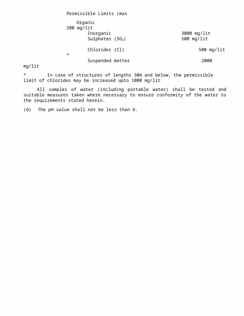
Tender No: CE(P) BCN/49 / 2009-10 Ser Page No:156 CANO: CE(P) BCN/ / 2010-11
(iv) The Contractor shall furnish to the Employer a copy of certified test reports from the manufacturer of glass beads obtained from a reputed laboratory showing results of all tests specified herein and shall certify that the material meets all requirements of this Specification. However, if so required, these tests may be carried out as directed by the Engineer.
31.4.4. Application properties of thermoplastic material
1he thermoplastic martial shall readily get screeded/extruded at temperatures specified by the manufacturers for respective method of application to produce a line of specified thickness which shall be continuous and uniform in shape having clear and sharp edges.
The material upon heating to application temperatures, shall not exude fumes, which are toxic, obnoxious or injurious to persons or property.
31.4.5. Preparation:
(i) The material shall be melted in accordance with the manufacturer‟s instructions in a heater fitted with a mechanical stirrer to give a smooth consistency to the thermoplastic material to avoid local overheating. The temperature of the mass shall be within the range specified by the manufacturer, and shall on no account be allowed to exceed the maximum temperature stated by the manufacturer. The molten material should be used as expeditiously as possible and for thermoplastic material which has natural binders or is otherwise sensitive to prolonged heating, the material shall not be maintained in a molten condition for more than 4 hours.
(ii) After transfer to the laying equipment, the material shall be maintained within the temperature range specified by the manufacturer for achieving the desired consistency for laying.
31.4.6. Properties of finished road marking:
(a) The stripe shall not be slippery when wet.
(b) The marking shall not lift from the pavement in freezing weather.
(c) After application and proper drying, the stripe shall show no appreciable deformation or discolouration under traffic and under road temperatures upto 600C.
(d) The marking shall not deteriorate by contact with sodium chloride, calcium chloride or oil drippings from traffic.
(e) The stripe or marking shall maintain its original dimensions and position. Cold ductility of the material shall be such as to permit normal movement with the road surface without chopping or cracking.

(f) The colour of yellow marking shall conform to IS Colour No. 356 as given in IS: 164.

Tender No: CE(P) BCN/49 / 2009-10 Ser Page No:157 CANO: CE(P) BCN/ / 2010-11
31.7. Measurements for Payment
31.7.1 The painted markings shall be measured in sq. metres of actual area marked (excluding the gaps, if any).
31.7.2 In respect of markings like directional arrows and lettering, etc., the measurement shall be by numbers.
31.8. Rate
The Contract unit rate for road markings shall be payment in full compensation for furnishing all labour, materials, tools, equipment, including all incidental costs necessary for carrying out the work at the site conforming to these Specifications complete as per the approved drawings(s) for as directed by the Engineer and all other incidental costs necessary to complete the work to these Specifications.
32. QUALITY CONTROL FOR ROAD WORKS32.1 GENERALi) All materials to be used, all methods adopted and all works performed shall be strictly in accordance with the requirements of these Specifications. The Contactor shall set up a field laboratory at locations approved by the Engineer and equip the same with adequate equipment and personnel in order to carry out all require tests and Quality Control work as per Specifications and/or as directed by the Engineer. The internal layout of the laboratory shall be as per Clause 121 of MORST&H Specifications for road and Bridge works (Fourth Revision) and/or as directed by the Engineer. The list of equipment and the facilities to be provided shall be got approved from the Engineer in advance.

Tender No: CE(P) BCN/49 / 2009-10 Ser Page No:158 CANO: CE(P) BCN/ / 2010-11
ii) The Contractor’s laboratory should be manned by a qualified Materials Engineer/Civil Engineer assisted by experienced technicians, and the set-up should be got approved by the Engineer.iii) The Contractor shall carry out quality control tests on the materials and work to the frequency stipulated in subsequent paragraphs. In the absence of clear indications about method and or frequency of tests for any item, the instructions of the Engineer shall be followed.iv) For satisfying himself about the quality of the materials and work, quality control tests will also be conducted by the Engineer (by himself, by his Quality Control units or by any other agencies deemed fit by him), generally to the frequency set forth herein under. Additional tests may also be conducted where, in the opinion of the Engineer, need for such test exists.v) The Contractor shall provide necessary co-operation and assistance in obtaining the samples for tests and carrying out the field tests as required by the Engineer from time to tome. This may include provision of labour, attendants, assistance in packing and dispatching and any other assistance considered necessary in connection with the tests.vi) For the work of embankment, subgrade and pavement, construction of subsequent layer of same or other material over the finished layer shall be done after obtaining permission form the Engineer. Similar permission from the Engineer shall be obtained in respect of all other items of works prior to proceeding with the next stage of construction.vii) The Contractor shall carry out modifications in the procedure of work, if found necessary, as directed by the Engineer during inspection. Works falling short of quality shall be rectified/redone by the Contractor at his own cost, and defective work shall also be removed from the site of works by the Contractor at his own cost.viii) The cost of laboratory building including services, essential supplies like water, electricity, sanitary services and their maintenance and cost of all equipment, tools, materials, labour and incidentals to perform tests and other operations of quality control according to the Specification requirements shall be deemed to be incidental to the work and no extra payment shall be made for the same. If, however, there is a separate item in the Bill of Quantities for setting up of a laboratory and installing testing equipment, such work shall be paid for separately.ix) For testing of samples of soils/soil mixes, granular materials, and mixes, bituminous materials and mixes, aggregates, cores etc., samples in the required quality and form shall be supplied to the Engineer by the Contractor at his own cost.x) For cement, bitumen, mild steel, and similar other materials where essential tests are to be carried out at the manufacturer’s plants or at laboratories other than the site laboratory, the cost of samples, sampling, testing and furnishing of test certificates shall be borne by the Contractor. He shall also furnish the test certificates to the Engineer.
xi) For testing of cement concrete at site during construction, arrangements for supply of samples, sampling, testing and supply of test results shall be made by the Contractor as per the frequency and number of tests specified in the Handbook of Quality Control for Construction of Roads and Runways (IRC: SP: 11) and relevant IS Codes or relevant clauses of these Specifications, the cost of which shall be borne by the Contractor.
xii) The method of sampling and testing of materials shall be as required by the “Handbook of Quality Control for Construction of Roads and Runways” (IRC: SP: 11), and these MORST&H Specifications. Where they are contradicting, the provision in these Specifications shall be followed. Where they are silent, sound engineering practices shall be adopted. The sampling and testing procedure to be used shall be as approved by the Engineer and his decision shall be final and binding on the Contractor.

Tender No: CE(P) BCN/49 / 2009-10 Ser Page No:159CANO: CE(P) BCN/ / 2010-11
xiii) The materials for embankment construction shall be got approved from the Engineer. The responsibility for arranging and obtaining the land for borrowing or exploitation in any other way shall rest with the Contractor who shall ensure smooth and uninterrupted supply of materials in the required quality during the construction period.
xiv) Similarly, the supply of aggregates for construction of road pavement shall be from quarries approved by the Engineer. Responsibility for arranging uninterrupted supply of materials from the source shall be that of the Contractor.
32.2 DEFECTIVE MATERIALSAll materials which the Engineer/his representative has determined as not conforming to the
requirements of the Contract shall be rejected whether in place or not; they shall be removed immediately from the site as directed. Materials, which have been subsequently corrected, shall not be used in the work unless approval is accorded in writing by the Engineer. Upon failure of the Contractor to comply with any order of the Engineer/his representative, given under this Clause, the Engineer/his representative shall have authority to cause the removal of rejected material and to deduct the removal cost thereof from any payments due to the Contractor.
32.3 IMPORTED MATERIALSi) At the time of submission of tenders, the Contractor shall furnish a list of materials/finished products manufactured, produced or fabricated outside India which he proposes to use in the work. The Contractor shall not be entitled to extension of time for acts or events occurring outside India and it shall be the Contractor’s responsibility to make timely delivery to the job site of all such materials obtained from outside India.
ii) The materials imported from outside India shall conform to the relevant Specifications of the Contracted. In case where materials/finished products are not covered by the Specifications in the Contract, the details of Specifications proposed to be followed and the testing procedure as well as laboratories/ establishments were tests are to be carried out shall be specifically brought out and agree to in the Contract..
iii) The Contractor shall furnish to the Engineers a certificate of compliance of the tests carried out. In addition, certified mill test reports clearly indentified to the lot of materials shall be furnished at the Contractor’s cost.
33. CONTROL OF ALIGNMENT, LEVEL AND SURFACE REGULARITY33.1 GENERAL
All works performed shall conform to the lines, grades, cross sections and dimensions shown on the drawings or as directed by the Engineer, subject to the permitted tolerances described herein-after.
33.2 HORIZONTAL ALIGNMENTHorizontal alignments shall be reckoned with respect to the centre line of the carriageway as shown
on the drawings. The edges of the carriageway as constructed shall be correct within a tolerance of + 10 mm there from. The corresponding tolerance for edges of the roadway and lower layers of pavement shall be + 25 mm.
33.3 SURFACE LEVELSi) The levels of the subgrade and different pavement courses as constructed, shall not vary from those calculated with reference to the longitudinal and cross-profile of the road shown on the drawings or as directed by the Engineer beyond the tolerances mentioned in Table 900-1.

Tender No: CE(P) BCN/49 / 2009-10 Ser Page No:160CANO: CE(P) BCN/ / 2010-11
Table 900-1. Tolerances in surface levels
1. Subgrade + 20 mm - 25 mm
2. Sub-base + 10 mm(a) Flexible pavement - 20 mm(b) Concrete pavement + 6 mm
[Dry lean concrete or Rolled - 10 mmconcrete]
3. Base-course for flexible pavement(a) Bituminous course + 6 mm -
6 mm(b) Other than bituminous + 10 mm
(i) Machine laid - 10 mm + 15 mm
(ii) Manually laid - 15 mm4. Wearing course for flexible pavement
(a) Machine laid + 6 mm - 6 mm
(b) Manually laid + 10 mm - 10 mm
ii) Provided, however, that the negative tolerance for wearing course shall not be permitted in conjunction with the positive tolerance for base course, if the thickness of the former is thereby reduced by more than 6 mm for flexible pavements and 5 mm for concrete pavements.
iii) For checking compliance with the above requirement for subgrade, sub-base and base courses, measurements of the surface levels shall be taken on a grid of points placed at 6.25 m longitudinally and 3.5 m transversely. For any 10 consecutive measurements taken longitudinally or transversely, not more than one measurement shall be permitted to exceed the tolerance as above, this one measurement being not in excess of 5 mm above the permitted tolerance.
iv) For checking the compliance with the above requirement for bituminous wearing courses and concrete pavements, measurements of the surface levels shall be taken on a grid of points space at 6.25 mm along the lengthy and at 0.5 mm from the edges and at the centre of the pavement. In any length of pavement, compliance shall be deemed to be met for the final road surface, only if the tolerance given above is satisfied for any point on the surface.
33.4 SURFACE REGULARITY OF PAVEMENT COURSES
i) The longitudinal profile shall be checked with a 3 metre long straight edge/moving straight-edge as desired by the Engineer at the middle of each traffic lane along a line parallel to the centre line of the road.
Tender No: CE(P) BCN/49 / 2009-10 Ser Page No:161CANO: CE(P) BCN/ / 2010-11

ii) The maximum permitted number of surface irregularities shall be as per Table 900-2.
Surfaces of carriageways and paved shoulders
S u r f a c e s o f l a y b y s , s e r v i c e areas and all bituminous base courses
Irregularity 4 mm 7 mm 4 mm 7 mm
Length (m) 300 75 300 75 300 75 300 75
National Highways/ Expressway s*
20 9 2 1 40 18 4 2
Roads oflowercategory*
40 18 4 2 60 27 6 3
* Category of each section of road as described in the Contract.
iii) The maximum allowable difference between the road surface and underside of a 3 m straight-edge when placed parallel with, or at right angles to the centre line of the road at points decided by the Engineer shall be:
For pavement surface (bituminous and cement concrete) 3 mm
For DBM/bituminous base courses 6 mm
For NFSSB/base courses 8 mm
For sub-bases under concrete pavements 10 mm.
33.5 RECTIFICATION
Where the surface regularity of subgrade and the various pavement courses fall outside the specified tolerances, the Contractor shall be liable to rectify these in the manner described below and to the satisfaction of the Engineer.
(i) Subgrade: Where the surface is high, it shall be trimmed and suitably compacted. Where the same is low, the deficiency shall be corrected by scarifying the lower layer and adding fresh material and recompacting to the required density. The degree of compaction and the type of material to be used shall conform to the requirements of Clauses 305 of MORST&H Specifications for road and Bridge works (Fourth Revision).
(ii) Granular Sub-base: Same as at (i) above, except that the degree of compaction and the type of material to be used shall conform to the requirements of Clauses 401 of MORST&H Specifications for road and Bridge works (Fourth Revision).
Tender No: CE(P) BCN/49 / 2009-10 Ser Page No:162CANO: CE(P) BCN/ / 2010-11
(iii) Water Bound Macadam/Wet Mix Macadam Sub-base/Base: Where the surface is high or low, the top 75 mm shall be scarified, reshaped with added materials as necessary and recompacted to Clause 404 of MORST&H Specifications for road and Bridge works (Fourth Revision). This shall also apply to wet mix macadam to Clauses 406 of MORST&H Specifications for road and Bridge works (Fourth Revision).(iv) Bituminous Constructions: For bituminous construction other than wearing course, where the surface is low, the deficiency shall be corrected by adding fresh material over a suitable tack coat if needed and recompacting to specifications. Where the surface, is high, the full depth of the layer shall be removed and replace with fresh material and compacted to specifications. For wearing course, where the surface is high or low, the full depth of the layer shall be removed and replace with fresh material and compacted to specifications. In all cases where the removal and replacement of a bituminous layer is involved, the area treated shall not be less than 5 m lengthy and not less than 3.5 m width.
34. DRAWING OF PMT WORKS:-
Standard drawings of permanent works such as R/Walls, B/ Walls, T/Walls, RCC culverts of various sizes, Drains and Parapet walls etc alongwith road alignment map showing the alignment of KSA road Serially numbered from Page No: 01 to 25 is enclosed separately for your reference and guidance purpose only. However Drawings for each structure as per ground condition will be provided by OC Contract to execute work at the time of execution. Contractor to execute work as per drawing provided by OC Contract. Drawings however provided with tender document are for rough guidelines only
35. QUALITY CONTROL TESTS DURING CONSTRUCTION
35.1 GENERALMaterials supplied and the works carried out by the Contractor shall conform to the
specifications prescribed in the preceding Clauses.For ensuring the requisite quality of construction, the materials and works shall be subjected to quality control tests, as described hereinafter. The testing frequencies set forth are the

desirable minimum and the Engineer shall have the full authority to carry out additional tests as frequently as he may deem necessary, to satisfy himself that the materials and works comply with the appropriate specifications. However, the number of tests recommended in Tables 900-3 and 900-4 may be reduced at the discretion of the Engineer if it is felt that consistency in the quality of materials can still be maintained with the reduced number of tests.
Test procedures for the various quality control tests are indicated in the respective Sections of these Specifications or for certain tests within this Section. Where no specific testing procedure mentioned, the tests shall be carried out as per the prevalent accepted engineering practice to the directions of the Engineer in charge/ OC contract.
35.2 CONTROL TESTS AND THEIR MINIMUM FREQUENCY

Tender No: CE(P) BCN/49 / 2009-10 Ser Page No:163CANO: CE(P) BCN/ / 2010-11

TABLE 900-3.
Sl. Type of Test Frequency (min.)No.
1. Granular (i) Gradation One test per 200 m3
(ii) Atterberg limits One test per 200 m3
(iii) Moisture Content One test per 250 m 2
Prior tocompaction
(iv) Density of Compacted layer
One test per 500 m 2
(v) Deleterious Constituents
As required
(vi) C.B.R. As required2. Water Bound (i) Aggregate Impact One test per 200
Macadam Value m3 of Aggregate
(ii) Grading One test per 100m3
(iii) Flakiness One test per 200and
Elongationm3 of aggregate
Index(iv) Atterberg limits of One test per 25 m3
binding material of binding material(v) Atterberg limits of One test per 100
portion of cubic metre ofaggregate passing aggregate
425 micron sieve

35.3 TESTS ON BITUMINOUS CONSTRUCTION
Tests on and frequency: The Tests and their minimum frequencies for the different types of bituminous works shall be as given in Table 900-4. The Engineer may direct additional testing as required.
Tests on and frequency: The Acceptance criteria for tests on density and Marshall stability shall be subject to the condition that the mean value is not less than the specified value plus:
1.65 - 1.65 Times the standard devotion(No, of samples) 0.5
Tender No: CE(P) BCN/49 / 2009-10 Ser Page No:164CANO: CE(P) BCN/ / 2010-11
35.4 CONTROL TESTS FOR BITUMINOUS WORKS, AND THEIR MINIMUM FREQUENCY
TABLE 900-4.Sl. Type of Test Frequency (min.)No .
Construction
1. Primer Coat/Tack Coat/Fog Spray
(i) Quality of binder Number of samples per lot and test as per IS: 73, IS: 217 and IS: 8887 as applicable.
(ii) Bindertemperature for application
At regular close intervals
(iii) Rate of spread of Binder
One test per 500 m2 and not less than two tests per day.
2. DenseBituminousMacadam/SemiDenseBituminousConcrete/Bituminous Concrete
(i) Quality of binder Same as mentioned under Serial No. 1
(ii) Aggregate Impact Value/Los Angeles
One test per 50 Sqm of aggregate

(iii) Flakiness Index and Elongation Index
-do-
(iv) Stripping Value Initially one set of 3 representative specimens foreach source of supply. Subsequently when warrantedby change in the quality of aggregates.
(v(v) Soundness Initially, determination by each(Magnesium and method for each source of
Sodium Sulphate)
supply, then as warranted by change in the quality of aggregates
(vi) Water absorption of aggregates
As in Serial No. 2 (iv)
(vii) Sand equivalent test
As required
(vi i i)
Plasticity Index As required(ix) Polished
stone valueAs required.
(x) Percentage of When gravel is used, one test perfractured faces 50 cum of aggregate
(xi) Mix grading One set of test on individual constituents and mixed aggregate from the dryer for each 400 tonnes of mix subject to a minimum of to test per plant per day.
Tender No: CE(P) BCN/49 / 2009-10 Ser Page No:165CANO: CE(P) BCN/ / 2010-11
(xii) Stability of Mix For each 400 tonnes of mixproduced, a set of 3 Marshall specimens to be prepared and tested for stability, flow value, density and void content subject to a minimum of two sets being tested per plant per day.
(xiii) Water sensitivity of mix (Retained Tensile Strength
As in Serial No. 2 (iv), if required.
(xiv) Swell test on the mix
As required for the Bituminous Concrete
(xv) Control of temperature of binder in boiler, aggregate in the dryer and mix at the time
At regular close intervals

of laying and rolling
(xvi) Control of binder contents and grading of the mix
One test for each 400 tonnes of mix subject to a minimum of two tests per day per plant.
(xvii) Rate of spread of mixed material
Regular control through checks on the weight of mixed materials and layer thickness
(xviii)
Density of compacted layer
One test per 250 sqm area
35.5 FREQUENCY OF QUALITY CONTROL TESTS FOR PAVINGQUALITY CONCRETE
TABLE 900-6. 1. Levels, alignment and texture
(i) Level tolerance Clause 902.3(ii) Width of pavement and position of paving Clause 902.2
edges(iii) Pavement thickness Clauses 902.3
and 903.5.2.3
Tender No: CE(P) BCN/49 / 2009-10 Ser Page No:166CANO: CE(P) BCN/ / 2010-11(iv) Alignment of joints, widths, depths of dowel To be checked @ grooves one Joint per 400 m
length or a day’s work whichever is
more.(v) Surface regularity both transversely and Once a day or onelongitudinally day’s work, without disturbing the
curing operation..(vi) Alignment of dowel bars and their To be checked
In trial length as
accuracy/tie bars per Clauses 602.10.5.2 and
once on every 2 kM(vii) Texture depth Clause 602.9.8
2. Quality of Materials and Concrete
Control tests for materials and concrete shall beas under:
1. Cement` Physical and IS: 269 Once for each source ofchemical tests
IS: 455 supply and occasionallyIS: 1489 when called for in case ofIS: 8112 long/improper storage.IS: Besides, the Contractor also12269 will submit daily test dataon cement released by theManufacturer. IS: 2386 One test for every day’s Pt.1) work of each fraction of
coarse aggregate and fine
aggregate initially: may be relaxed later at the discretion of the discretion of the Engineer.
(ii) Deleterious IS: 2386 -do-Constituents (Pt.2)
(iii) Water IS: 2386 Regularly as required subject to
Absorption (Pt 3) a minimum of one test a day for Coarse aggregate & two tests a day for fine aggregate. This data shall be used for correcting the water demand of the mix on daily basis.
Tender No: CE(P) BCN/49 / 2009-10 Ser Page No:167CANO: CE(P) BCN/ / 2010-113. Coarse (i) Los Angles IS: Once for each source of
Aggregate Abrasion value 2386 supply and subsequently
Or aggregate impact ( Pt; 4) on monthly basis.
(ii) Soundness IS: Before approving the 2386 aggregate and every (Pt 5) month subsequently.
(iii) Alkali IS: -do-Aggregate 2386Reactivity (Pt 7)
4. Water Chemical tests IS: 456 Once for approval of
Coarse and (i) Gradation Fineaggregates
2.

Source of supply, subsequently only in case of doubt.
5. Concrete (i) Strength of IS:516 2 cubes and 2 beams per Concrete 150 cum or part thereof
( once for 7 days and other for 28 days strength) or minimum 6 cubes and 6 beams per day’s work whichever is more.
(ii) Core strength IS 516 As per the requirement of On hardened the Engineer, only in case Concrete of doubt.
(iii) Workability IS: 1199 One test per each dumper of fresh concrete load at both Batching Slump test plant site and paving site
initially when work starts. Subsequently sampling may be done from alternate dumper.
(iv) Thickness Form the level date of determination concrete pavement surface
and sub base at grid points of 5/6.25m x 3.5 m.
(v) Thickness 3 cores per trial length.Measurement for Trial length
(vi) Verification of String line or steel formsLevel of string line shall be checked for
levelsIn the case of slip at an interval of 5.0 m or
Tender No: CE(P) BCN/49 / 2009-10 Ser Page No:168CANO: CE(P) BCN/ / 2010-11
Form paving and steel 6.25 m. The level toleranceForms in the case of allowed shall be + 2 mm. fixed form paving These shall be got
approved 1-2 hours before the commencement of the concreting activity.


Tender No: CE(P) BCN/49/2009-10 Ser Page No 169CA No: CE(P) BCN/ / 2010-11
Appendix ‘B’(Ref para-38 of Special Condition of tender)
NEFT/RTGS MANDATE FORM(1) Name of firm/contractor as
per account in the Bank(2) Beneficiary’s Account Number
(As appearing on the Cheque Book)
(3) Name of Bank where a/c is held
(4) Name of Branch
(5) Address of Branch
(6) Telephone No. of Branch
(7) IFSC Code of Branch
(8) 9-Digit MICR Code Number of the Bank & Branch
(9) E-Mail ID of Contractor
Note Please attach a blank cancelled cheque for verification of the above particulars.
I, hereby, declare that the particulars given above are correct and complete. If the transaction is delayed or not effected due to incomplete or incorrect information of the bank details, I will not hold the payment releasing authority responsible for it.
Dated : Signature of the contractor (Seal)CERTIFICATE BY BANK
Certified that the particulars furnished above are correct as per our records.
Seal of Bank Signature of the branch manager of the BankDated:-
CA NO CE (P) BCN / /2010-11 Serial page No.170Tender No: CE (P) BCN/49/2009-10

E- Mail: [email protected] Web site: www.bro.nic.in [email protected] www.gref.nic.in
BORDER ROADS ORGANISATIONCHIEF ENGINEER PROJECT BEACON
NOTICE OF TENDER
1. A sealed tender is invited for “Construction/improvement and surfacing work of Kishtwar-Sinthanpass - Anantnag road between km 46.00 to km 83.00 to NHDL specifications to be executed through contract as turn key Project under 35 BRTF sector Project Beacon in J&K State.”2. The tender documents may be downloaded from BRO web site http://www.bro.nic.in. and printout is to be taken on A4 size paper. It is advisable that the downloaded tender documents to be printed through laser printer only. Submission of Xerox copy or photo copy of tender or tender print not taken on A4 size of paper is not permitted and liable to be rejected.3. The work is estimated to cost Rs. 5933.00 Lac (Rupees Fifty nine crore thirty three lac only). This estimate, however, is not a guarantee and is merely given as a rough guide and if the work costs more or less, the tenderer will have no claim on that account.
4. The tender shall be based on General Conditions of Contract based on IAFW-2249 & IAFW-1779 (A), Special Conditions and Particular Specifications with Schedule `A’ (List of works) to be priced by the tenderers.5. Not more than one tender shall be submitted by one contactor or one firm of contractors. Under no circumstance will father and his son(s) or other close relation having business dealing with one another be allowed to tender for the same contract, as separate competitors. A breach of this condition will render tenders of both parities liable for rejection.6. The work is to be completed within 24 (twenty four) months in accordance with the phasing, if any, indicated in the tender form the date of handing over the site, which will be within one month from the date of acceptance letter.7. Interested tenderer may also submit application in the office of the HQ CE(P) Beacon , C/o 56 APO so as to reach this HQ on or before 30 days after publication in news paper, i.e, 21 Mar 2010. However Invitation of application for issue of tender does not constitute any guarantee for issue of tender to the applicant even to enlisted contractors of appropriate class. Issue of tender will be decided by the Accepting Officer based on past track records, financial position and experience of similar work of the applicant/contractor. The decisions of the Accepting Officer for issue of tender or otherwise to the applicant/contractor shall be final and the applicant/contractor will not be entitled for any compensation for rejection of his application. Tender forms and conditions of contract and others necessary documents will be issued on 22 Mar 2010 by speed post.
8. The Chief Engineer, Project Beacon, C/O 56 APO will be the Accepting Officer, hereinafter, referred to as such for the purpose of this contract.9. Tender ( in full) T- Bid and Q- Bid either downloaded from BRO website or issued by BRO will be received by HQ CE(P) Beacon, C/o 56 APO at 1200 Hrs on 05 May 2010 as per procedure laid down in tender documents and Part –I containing ( Un priced bid) will be opened immediately after receipt on same day and Part –II ( Priced bid) of all the tenderer shall be put in one envelop and sealed by the opening officers. Same will be opened later on 26 May 2010 in respect of qualified tenderer.
CA NO CE (P) BCN / /2010-11 Serial page No.171Tender No: CE (P) BCN/49/2009-10
(NOTICE OF TENDER (contd…….)

10. Intending tenderers are advised to visit BRO website three days prior to date of opening of tender for any corrigendum /addendum/ amendment. Tender received after due date shall not be considered for opening and no reason for delay or claim whatsoever shall be entertained.
11. The tenderer shall note that earnest money is not required to be deposited. However all the tenderers whether enlisted with BRO or not, will have to deposit the tender guarantee amounting to Rs 30,00,000/- only ( Rupees Thirty lac only) in the form of Bank guarantee as per special condition of contract document.
12. Copies of drawings and other documents pertaining to the work required to be signed for the purpose of identification by the Accepting Officer or his accredited representative and the sample of materials and stores to be supplied by the contractor will be opened for inspection at the following locations:-
Chief Engineer (P) Beacon, C/O 56 APO
13. Tenderers are advised to visit site by making prior appointment with Commander 35 BRTF, C/O 56 APO in advance. Tenderers are requested to have copies of Drawings of Fmn, surfacing and Pmt Structures like R/Wall, B/ Wall, RCC culverts and X section and L section of road etc from HQ 35 BRTF C/o 56 APO.
14. A tenderer shall be deemed to have full knowledge of all relevant documents, samples, site etc whether he has inspected them or not.
15. Any tender which stipulates any alterations to any of the conditions laid down or which proposes any other condition of any description whatsoever is liable to be rejected.
16. The Accepting Officer reserves his right to accept a tender submitted by a Public Undertaking, giving a Price preference over other tender(s) which may be lower, as are admissible under the Govt policy. No claim for any compensation or otherwise shall be admissible from such tenderers whose tenders may be rejected on account of the said policy.
17. The submission of a tender by a tenderer implies that he had read this notice and conditions of contract and has made himself aware of the scope and specifications of the work to be done and of the conditions and rates at which factors bearing on the execution of the work.
18. Applicant contractor have to attach a demand draft for Rs 3,000/- only ( Rupees Three thousand only ) in favour of Accepting officer i.e. CE(P) Beacon, C/o 56 APO and payable at SBI, Rawalpora, Srinagar, Bank Code No 6868 obtained from any Nationalized/ scheduled Bank valid for six months with their application as the cost of tender forms/ documents. The all applicable Bank charges shall be born by the applicant and he shall not have any claim what so ever on this account on Govt. In case of re- tendering, the firms which submitted the DD in earlier calls will require to submit DD along with their application also. Tender not accompanied with the cost of tender documents is lable to be rejected. However, public sector undertaking / Govt undertaking firms are exempted from the payment towards cost of tender documents.
CA NO CE (P) BCN / /2010-11 Serial page No.172Tender No: CE (P) BCN/49/2009-10
.(NOTICE OF TENDER(contd…….)

19. The Demand Draft attached with the applications form shall be non re- fundable if the tender documents are issued to the contractors, However, it shall be returned to the applicant by the Accepting Officer in case the tender form is not issued.20. The applicant contractor shall not become automatically entitled for issue of tender by virtue of enclosing DD along with the application and the Accepting Officer shall reserve the right to deny issue of tender to any applicant contractor.
21. In case of selective tendering or where in adequate applications are received suitable contractor may be selected and they shall also be asked to forward DD towards the cost of tender. Tenders will be issued to such contractors only thereafter.22. The Accepting Officer does not bind himself to accept the lowest or any tender or to give any reasons for not doing so.23. Tenderer who have downloaded the tender from the BRO website shall submit declaration along with tender documents that I/we have downloaded the tender from BRO website www.bro.gov.in or www.bro.nic.in and I/we have not tempered/ modified the tender from in any manner. In case if the same is found to be tempered modified in any manner, I/we understand that my/our tender will be summarily rejected and I/we are liable to be banned from doing business with BRO.
24. For further particulars, you may also see “ Indian Trade Journal” dated 17 Feb 2010 and refer bro website http:/www.bro.nic.in and http:// www.gref.nic.in.
25. This notice of tender shall form part of the contract.Sd/ x x x x x
Signature of Contractor SWDated:_____________ 2010 For Accepting OfficerCase file No: 800160/ 03/E8 Dated: 20 Jan 2010HeadquartersChief EngineerProject Beacon C/O 56 APODistribution: -1. HQ CE (P) Chetak, C/O 56 APO 11. HQ 32 BRTF C/O 56 APO 2. HQ CE (P) Sampark/O 56 APO 12. HQ35 BRTF C/O 56 APO 3. HQ CE (P) Swastik, C/O 99 APO 13 HQ 760 BRTF C/O 56 APO4. HQ CE (P) vartak, C/O 99 APO 14. AO (P) Beacon C/O 56 APO5. HQ CE (P) Pushpak, C/O 99APO 15. AO 35 BRTF C/O 56 APO 6. HQ CE (P) Sewak, C/O 99APO 16. 52 RCC C/O 56 APO7. HQ CE (P) Dantak, C/O 99APO 17. 118 RCC C/O 56 APO8. HQ CE (P) Udayak, C/O 99 APO 18. 5114 RCC C/O 56 APO9. HQ CE (P) Hirak, Hydrabad House10. HQ CE (P) Deepak, C/O 56 APO 19. Chief Engineer, Srinagar Zone, BB Cantt20. SE, PWD, Srinagar, 21. Chamber of Kashmir , HMP Owners Association22. HQ CE(P) Shivalik, C/o 56 APO Panthachowk, Near J&K Bank Ltd. Srinagar (J&K)23. HQ CE(P) Arunank, C/o 99 APO 24. HQ DGBR/ E8 section25. HQ CE(P) Himank, C/o 56 APO 26. HQ CE(P) Setuk, C/o 99 APO

CA NO: CE (P) BCN/ /2010-11 Srl Page No:173Tender No: CE (P) BCN/49/2009-10
AMENDMENT NO: 01 TO NIT DATED 20 JAN 2010AMENDMENT NO. 01 FOR CONSTRUCTION/IMPROVEMENT AND SURFACING WORK OF KISHTWAR-SINTHANPASS - ANANTNAG ROAD BETWEEN KM 46.00 TO KM 83.00 TO NHDL SPECIFICATIONS TO BE EXECUTED THROUGH CONTRACT AS TURN KEY PROJECT UNDER 35 BRTF SECTOR PROJECT BEACON IN J&K STATE.”1. Reference NIT issued vide our letter No 800160/ 03/E8 dated 20 Jan 2010.2. The following amendment is issue to the NIT dated 20 Jan 2010
Ser No
Refer For/Read
Particulars
(a) Ser Page
No: 01, Para 7
For Interested tenderer may also submit application in the office of the HQ CE(P) Beacon , C/o 56 APO so as to reach this HQ on or before 30 days after publication in news paper, i.e, 21 Mar 2010. However Invitation of application for issue of tender does not constitute any guarantee for issue of tender to the applicant even to enlisted contractors of appropriate class. Issue of tender will be decided by the Accepting Officer based on past track records, financial position and experience of similar work of the applicant/contractor. The decisions of the Accepting Officer for issue of tender or otherwise to the applicant/contractor shall be final and the applicant/contractor will not be entitled for any compensation for rejection of his application. Tender forms and conditions of contract and others necessary documents will be issued on 22 Mar 2010 by speed post.
Read Interested tenderer may also submit application in the office of the HQ CE(P) Beacon , C/o 56 APO so as to reach this HQ on or before 08 May 2010. However Invitation of application for issue of tender does not constitute any guarantee for issue of tender to the applicant even to enlisted contractors of appropriate class. Issue of tender will be decided by the Accepting Officer based on past track records, financial position and experience of similar work of the applicant/contractor. The decisions of the Accepting Officer for issue of tender or otherwise to the applicant/contractor shall be final and the applicant/contractor will not be entitled for any compensation for rejection of his application. Tender forms and conditions of contract and others necessary documents will be issued on 12 May 2010 by speed post.
(b) Ser Page
No: 01, Para 9
For Tender ( in full) T- Bid and Q- Bid either downloaded from BRO website or issued by BRO will be received by HQ CE(P) Beacon, C/o 56 APO at 1200 Hrs on 05 May 2010 as per procedure laid down in tender documents and Part –I containing ( Un priced bid) will be opened immediately after receipt on same day and Part –II ( Priced bid) of all the tenderer shall be put in one envelop and sealed by the opening officers. Same will be opened later on 26 May 2010 in respect of qualified tenderer.
Read Tender ( in full) T- Bid and Q- Bid either downloaded from BRO website or issued by BRO will be received by HQ CE(P) Beacon, C/o 56 APO at 1200 Hrs on 18 Jun 2010 as per procedure laid down in tender documents and Part –I containing ( Un priced bid) will be opened immediately after receipt on same day and Part –II ( Priced bid) of all the tenderer shall be put in one envelop and sealed by the opening officers. Same will be opened later on 29 Jun 2010 in respect of qualified tenderer.
3. All other conditions will remain unchanged.4. This amendment shall form part of the tender documents and shall be returned duly signed by the tenderer along with tender documents.
Dated: 20 Mar 2010800160/ 18 /E8HeadquartersChief EngineerProject BeaconC/O 56 APODistribution: -All Concerned

CA NO: CE (P) BCN/ /2010-11 Srl Page No:174Tender No: CE (P) BCN/49/2009-10
AMENDMENT NO: 02 TO NIT DATED 20 JAN 2010
AMENDMENT NO. 02 FOR CONSTRUCTION/IMPROVEMENT AND SURFACING WORK OF KISHTWAR-SINTHANPASS - ANANTNAG ROAD BETWEEN KM 46.00 TO KM 83.00 TO NHDL SPECIFICATIONS TO BE EXECUTED THROUGH CONTRACT AS TURN KEY PROJECT UNDER 35 BRTF SECTOR PROJECT BEACON IN J&K STATE.”1. Reference NIT issued vide our letter No 800160/ 03/E8 dated 20 Jan 2010.
2. The following amendment is issue to the NIT dated 20 Jan 2010
Ser No
Refer For/Read
Particulars
(a) Ser Page
No: 02, Para 11
For The tenderer shall note that earnest money is not required to be deposited. However all the tenderers whether enlisted with BRO or not, will have to deposit the tender guarantee amounting to Rs 30,00,000/- only ( Rupees Thirty lac only) in the form of Bank guarantee as per special condition of contract document.
Read
The tender shall be accompanied by Earnest Money amounting to Rs 9,00,000/- only ( Rupees Nine lac only) in the form of term deposit receipt/FDR issued in favor of Chief Engineer Project Beacon, C/O 56 APO by a scheduled Bank, the amount being credited in the revenue deposit of Chief Engineer Project Beacon. The EMD shall be forfeited in case the tenderer revokes his offer after their tender is found to be the lowest.
3. All other conditions will remain unchanged.
4. This amendment shall form part of the tender documents and shall be returned duly signed by the tenderer along with tender documents.
Signature of ContractorSd/xxxxSWFor Accepting OfficerDated: 11 May 2010
800160/ 27 /E8HeadquartersChief EngineerProject BeaconC/O 56 APODistribution: -All Concerned

Tender No: CE(P) BCN/49 / 2009-10 CANO: CE(P) BCN/ / 2009-10
PART – I (‘T’-BID ) TENDER DOCUMENMTS
TO BE OPENED BY AN AUTHORISED OFFICER
CONSTRUCTION / IMPROVEMENT AND SURFACING WORK OF KISHTWAR-SINTHANPASS - ANANTNAG ROAD BETWEEN KM 46.00 TO KM 83.00 TO NHDL SPECIFICATIONS TO BE EXECUTED THROUGH CONTRACT AS TURN KEY PROJECT UNDER 35 BRTF SECTOR PROJECT BEACON IN J&K STATE.
TO BE OPENED AT 1205HRS ON 18 JUN 2010To
The Chief EngineerHQ CE(P) BeaconC/o 56 APO
M/s_____________________________________________________________
________________________________________________________________
________________________________________________________________
Signature of contractor Sd/xxxSWFor Accepting Officer
Tender No: CE (P) BCN/49/2009-10CA No: CE (P) BCN/ /2009-10
PART – I (‘T’-BID ) TENDER DOCUMENMTSTO BE OPENED BY AN AUTHORISED OFFICER
CONSTRUCTION / IMPROVEMENT AND SURFACING WORK OF KISHTWAR-SINTHANPASS - ANANTNAG ROAD BETWEEN KM 46.00 TO KM 83.00 TO NHDL SPECIFICATIONS TO BE EXECUTED THROUGH CONTRACT AS TURN KEY PROJECT UNDER 35 BRTF SECTOR PROJECT BEACON IN J&K STATE.
TO BE OPENED AT 1205HRS ON 18 JUN 2010To
The Chief EngineerHQ CE(P) BeaconC/o 56 APO
M/s__________________________________________________________
_____________________________________________________________
_____________________________________________________________

______________________(Signature of contractor) SW
For Accepting Officer