general report on 2012 cigre sc c4 hakodate...
TRANSCRIPT
1
GENERAL REPORT ON CIGRE SC C4 COLLOQUIUM IN HAKODATE, JAPAN -Fusion of Lightning Research and Practical for Power System in the Future-
Date: 10-13 October 2012, in Hakodate, Japan
Reported by Hideki MOTOYAMA, Chairperson of Local Organization Committee
0. Introduction
CIGRE SC C4 and the Japanese National Committee of CIGRE held the CIGRE SC C4 Colloquium in Hakodate, Japan from October 10 to October 13, 2012, with the theme “Fusion of Lightning Research and Practical for Power System in the Future.”
The colloquium started from the Invited Lecture, which was followed by seven sessions. In the Invited Lecture, three presenters delivered lectures. In each session, participants held candid discussions and exchanged their knowledge. The summary of the colloquium, including that of the technical tour, SC C4 Tutorial and WGs, is introduced below.
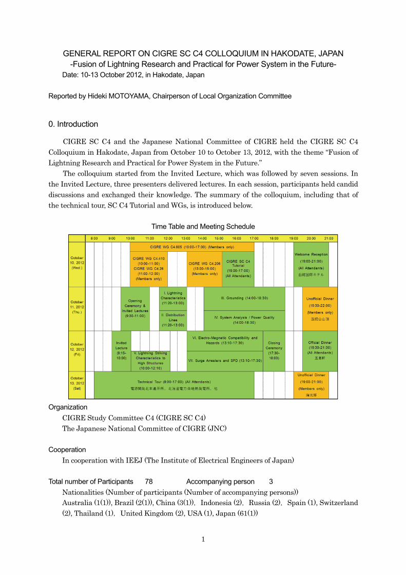
Time Table and Meeting Schedule
Organization
CIGRE Study Committee C4 (CIGRE SC C4) The Japanese National Committee of CIGRE (JNC)
Cooperation
In cooperation with IEEJ (The Institute of Electrical Engineers of Japan)
Total number of Participants 78 Accompanying person 3
Nationalities (Number of participants (Number of accompanying persons)) Australia (1(1)), Brazil (2(1)), China (3(1)),Indonesia (2),Russia (2),Spain (1), Switzerland (2), Thailand (1),United Kingdom (2), USA (1), Japan (61(1))
2
1. Invited Lecture
Titles of presentation:
(1) Invited Lecture 1 “Instrumentation of the Säntis Tower in Switzerland and Obtained Results After 18 Months of Operation”
F. Rachidi (EPFL) (2) Invited Lecture 2
“Ensuring Stable Electricity Supply and Expanding the Use of Renewable Energies in Hokkaido”
M. Ueno (HEPCO) (3) Invited Lecture 3
“CIGRE progress in the area of lightning protection of transmission and distribution lines” C. A. Nucci (University of Bologna), Former Chairperson of SC C4
Summary of session:
In the “Invited Lecture,” the opening session of the Colloquium, three presenters provided lectures. The lecture by Prof. F. Rachidi showed the general characteristics of lightning current measuring instruments deployed at Säntis Tower in Switzerland. He also demonstrated observed and analytical data obtained within the period of 18 months of operation. Mr. M. Ueno introduced several activities in Hokkaido Electric Power Company (HEPCO) implemented after the earthquake in March 2011. The activities aimed at developing power sources, expanding the use of renewable energies and securing a stable supply of electricity. Prof. C. A. Nucci’s lecture was presented by Prof. F. Rachidi and Prof. A. Ametani. The lecture summarized the work accomplished by CIGRE and CIGRE SC C4. Particularly, works related to the lightning protection of transmission and distribution lines were introduced.
3
2. Summary of Session
2.1 Session 1: Lightning Characteristics
Date and time October 11, 2012 11:20-13:00 Meeting room Sun Refre Hakodate, Room A Chairperson S. Visacro (Brazil) Moderator S. Sekioka (Japan) The number of participants 25 -30
Paper Titles:
Session Report S. Sekioka (Japan)
I-1: Overview about the Update of Lightning Location System of Chubu Electric Power Company and Its Evaluation
M. Shimizu, K. Momozawa, F. Suzuki, Y. Nakamura, T. Morimoto, Z. Kawasaki (Japan) I-2: Continuing Current Characteristics of Lightning Flashes Striking Transmission Lines in
Summer M. Miki, T. Miki. M. Shimizu (Japan)
I-3: Deducing Lightning Locations and Charge Moment Changes by ELF Network Observations in Japan
Y. Hobara, R. Nakamura, M. Hayakawa, K. Shiokawa (Japan) I-4: Horizontal Distribution of Lightning Discharges in a Single Event in Winter
N. Honma, D. Tsurushima, T. Konno (Japan)
Summary of session:
This session dealt with the data obtained from observation conducted for clarifying the lightning characteristics, as well as the analytical results derived from those data. M. Shimizu introduced the updated lightning location system and the observation setup employed in Chubu Electric Power Company (I-1). M. Miki presented the results obtained from the observation of long continuing currents of lightning flashes (I-2). Y. Hobara reported a new ELF (extremely low frequency) observation network, which enabled them to successfully derive lightning locations and associated electric charge moment change around Japan (I-3). N. Honma characterized the HLR (horizontally linear long-range) lightning events by analyzing the LEMPs (lightning electromagnetic pulses) in winter lightning (I-4). Questions and Answers:
I-1: Overview about the Update of Lightning Location System of Chubu Electric Power Company and Its Evaluation
Q1: Do LLS sensors enable the estimation of lightning striking location? A1: Yes, they do.
I-2: Continuing Current Characteristics of Lightning Flashes Striking Transmission Lines in Summer
Q1: Are there any differences in characteristics depending on months? A1: We have not yet analyzed whether there are differences. It is an issue that should be
solved in the future.
4
Q2: There are mainly two mechanisms causing melt of a conductor. One is due to a phenomenon called “Joule effect,” which is caused by current flowing into the conductor, and the other is due to the characteristics of lightning discharge with high temperature. Which do you think is more dominant?
A2: We think that the lightning current with long wave-tail duration is the main cause of melting a conductor.
I-3: Deducing Lightning Locations and Charge Moment Changes by ELF Network Observations in Japan
*: There was no discussion. I-4: Horizontal Distribution of Lightning Discharges in a Single Event in Winter
Q: Could you explain in detail the GC model that simulates electromagnetic fields propagating on the sea?
A: The model is fundamentally same as that of a downward CG model.
2.2 Session 2: Distribution Lines
Date and time October 11, 2012 11:00-13:00 Meeting room Sun Refre Hakodate, Room B Chairperson T. Shindo (Japan) Moderator K. Ishimoto (Japan) The number of participants 15 -20
Paper Titles:
Session Report K. Ishimoto (Japan)
II-1: Assessment of the Lightning Performance of Compact Overhead Distribution Lines F. Napolitano, A. Borghetti, D. Messori, C.A. Nucci (Italy),
M.L.B. Martinez, G.P. Lopes, J.I.L Uchoa (Brazil) II-2: Study on Lightning Hazard Evaluation for Low Voltage Distribution Systems
A. Asakawa, K. Ishimoto, J. Kato, K. Yano, H. Makino (Japan) II-3: Influence of Grounding Resistance Connected to Surge Arresters on Lightning Surge
Behavior Observed at Low-voltage Equipment T. Hidaka, T. Kawazoe, K. Ishimoto, A. Asakawa, A. Takahashi (Japan)
5
II-4: Installation of Earth Wire and Relocation of Arrester for the Improvement of the Lightning Protection System on Distribution Lines
R. Zoro, T. L. Sitanggang (Indonesia) Summary of session:
In this session, the latest knowledge essential for the lightning protection design in the distribution lines was introduced. F. Napolitano assessed the lightning performance of compact configuration lines in the MV-class and analyzed the effect of surge arresters installed along the MV overhead lines (II-1). A. Asakawa introduced the study results of lightning hazard evaluation for low voltage distribution system (II-2). T. Hidaka described the influence of grounding resistance-which was connected to surge arresters-on the lightning surge behavior at
consumer equipment (II-3). R. Zoro reported the effectiveness of installation of earth wire and relocation of arrester for improving the lightning protection system on distribution lines (II-4). Questions and Answers:
II-1: Assessment of the Lightning Performance of Compact Overhead Distribution Lines Q: Did you consider the transient behavior of grounding resistance? A: Ground resistance was simulated by a pure resistance. Therefore, transient
characteristics of ground resistance were not considered. II-2: Study on Lightning Hazard Evaluation for Low Voltage Distribution Systems
Q: What is the effective lightning protection design for reducing the lightning hazard of consumer equipment?
A: For reducing the lightning hazard of consumer equipment, the following two measures are effective; (i) employment of common grounding system in consumer equipment, (ii) installation of SPDs (Surge Protective Devices) on the consumer house network.
II-3: Influence of Grounding Resistance Connected to Surge Arresters on Lightning Surge Behavior Observed at Low-voltage Equipment
Q1: Did you consider the transient behavior of grounding resistance? A1: No. We did not consider the transient characteristics of ground resistance. Q2: Did you consider the lightning strokes to phase wires? A2: No. In this paper, we only dealt with the lightning stroke to the top of pole. We are
studying the cases of lightning strokes to phase wires. II-4: Installation of Earth Wire and Relocation of Arrester for the Improvement of the Lightning
Protection System on Distribution Lines Q: I think that the disconnection of a phase wire was caused by not the energy of lightning
current but the energy of arc currents after flashover. A: There is a possibility.
6
2.3 Session 3: Grounding
Date and time October 11, 2012 14:00-18:30 Meeting room Sun Refre Hakodate, Room A Chairperson A. Haddad (UK) Moderator K. Michishita (Japan)
The number of participants 40
Paper Titles:
Session Report K. Michishita (Japan)
III-1: A Study on Mutual Coupling between Vertical Grounding Electrodes K. Nakamura, A. Ametani, K. Yamabuki (Japan)
III-2: Non-Uniform Distributed Equivalent Circuits of Grounding Electrodes P. Yutthagowith (Thailand)
III-3: Modeling the Effective Length of Earthing Systems under Variable Frequency H. Griffiths, N. Harid, A. Haddad (U.K.)
III-4: Transient Grounding Characteristic of a 600 kW Class Wind Turbine K. Yamamoto, S. Sumi, S. Yanagawa, D. Natsuno (Japan)
III-5: Enhancement of Wind Turbine Earthing Systems A. El-Mghairbi, H.Griffiths, N. Harid, A. Haddad(U.K.)
III-6: Proposals for Improvement of the Lightning Performance of Transmission Lines Installed in Areas of Extremely Unfavorable Soil Conditions
S. Visacro, F. H. Silveria, D. C. Brasil (Brazil) III-7: Determining the Optimized Length of Tower Footing Grounding Electrodes to Improve the
Lightning Performance of Transmission Lines S. Visacro, F. H. Silveira (Brazil)
III-8: Photographic Investigations on Lightning Impulse Discharge Phenomena in Soil J. He, B. P. Zhang (China)
III-9: Case Studies of Recent Lightning Troubles in Traction Power Supply System H. Hayashiya, K. Matsuura, N. Koguchi, H. Yamamoto, T. Fujita (Japan)
Summary of session:
In this session, presenters introduced the latest finding obtained from the research concerning the transient characteristics of grounding electrode, which should be taken into account for protecting equipment from lightning damage. K. Nakamura investigated the mutual grounding impedance between vertical grounding electrodes, on the basis of experiments and FDTD simulations (III-1). P. Yutthagowith introduced the results obtained using the non-uniform distributed equivalent circuits of grounding electrodes (III-2). H. Griffiths presented the calculations and simulation studies that quantified the frequency dependence of the earth impedance of rod, horizontal and grid electrodes (III-3). K. Yamamoto demonstrated the results of experimental and analytical studies investigating the ground characteristics of wind turbine generator system (III-4). A. El-Mghairbi introduced the earthing system models developed for wind turbines, and demonstrated the results obtained from numerical computer simulations (III-5). S. Visacro proposed specific arrangements of grounding electrodes for ensuring reasonable lightning performance of transmission lines installed in areas with unfavorable soil conditions
7
(III-6). S. Visacro also made a presentation on a simplified method to determine the optimized length of tower-footing grounding electrodes (III-7). J. He reported on the discontinuous ionization phenomenon in the soil around the grounding electrode, which had been observed using X-ray film imaging (III-8). H. Hayashiya explained some of the major lightning troubles in traction power system (III-9).
Questions and Answers:
III-1: A Study on Mutual Coupling between Vertical Grounding Electrodes Q: What is the physical background of the decrease in the induction component with the
increase in the distance between grounding electrodes? A: It is due to the conductivity of ground.
III-2: Non-Uniform Distributed Equivalent Circuits of Grounding Electrodes Q: In the paper, the authors showed an example of simple geometry. Is the authors’ method
applicable to the cases with more complex geometry?
A: It would be an important topic in the future. We expect our method is applicable to those cases.
III-3: Modeling the Effective Length of Earthing Systems under Variable Frequency Q: Did you consider the ionizing effect of grounding resistance when high current was
applied to? Moreover, does the ionizing effect influence the effective length of the earthing system?
A: No. In this paper, we did not consider the ionizing effect. III-4: Transient Grounding Characteristic of a 600 kW Class Wind Turbine
Q: Why does the earthing impedance show the inductive characteristics? A: It is because of the low earthing resistance due to low resistivity.
III-5: Enhancement of Wind Turbine Earthing Systems Q: Where was the measuring point of the impedance shown in Fig. 4?
A: It was the current injection point. Meanwhile, Fig. 5 shows the calculated transient EPR at the tower foot.
III-6: Proposals for Improvement of the Lightning Performance of Transmission Lines Installed in Areas of Extremely Unfavorable Soil Conditions
Q: How far the measuring instrument can measure the ground resistivity?
A: It can measure the resistivity of up to 30kΩm. III-7: Determining the Optimized Length of Tower Footing Grounding Electrodes to Improve the
Lightning Performance of Transmission Lines Q: There might be a limit to the grounding resistance even if the horizontal length of the
electrodes is elongated. A: The actual length of electrodes is still shorter than their effective length. Therefore,
increasing the length of electrodes is effective for reducing grounding resistance of those electrodes.
III-8: Photographic Investigations on Lightning Impulse Discharge Phenomena in Soil Q: What was the grounding resistivity when the reported phenomena occurred?
A: We did not measure it. III-9: Case Studies of Recent Lightning Troubles in Traction Power Supply System
*: There was no discussion.
8
2.4 Session 4: System Analysis/Power Quality
Date and time October 11, 2012 14:00-17:30 Meeting room Sun Refre Hakodate, Room B Chairperson J. Ma (China) Moderator K. Yamashita (Japan) The number of participants 10
Paper Titles:
IV-1: CIGRE WG C4.605 -Modelling and Aggregation of Loads in Flexible Power Networks –
Scope and Status of the Work by June 2012 S. M. Villanueva (Spain), K. Yamashita (Japan), L. M. Korunović (Serbia),
S. Z. Djokić (U.K.), J. Matevosyan (U.S.A.), A. Borghetti (Italy), Z. Y. Dong (Australia), J. V. Milanović (U.K.)
IV-2: Overview of Existing Methodologies for Load Model Development K. Yamashita (Japan), S. M. Villanueva (Spain), S. Z. Djokić (U.K.), J. Ma (China),
A. Gaikwad (U.S.A.), Z. Y. Dong (Australia), J. V. Milanović (U.K.) IV-3: Overview of Existing Load Models and Their Applications
L. M. Korunović (Serbia), K. Yamashita (Japan), S. Z. Djokić (U.K.), F. Villella (Belgium), J. V. Milanović (U.K.), A. Gaikwad (U.S.A.), S. M. Villanueva (Spain)
IV-4: CIGRE WG C4.605 -Recommendations on Measurement Based and Component Based Load Modeling Practice
Z. Y. Dong (Australia), A. Borghetti (Italy), K. Yamashita (Japan), A. Gaikwad, P. Pourbeik (U.S.A.), J. V. Milanvoić (U.K.)
IV-5: Instantaneous Measurement Based Load Modeling J. Ma, X. Zheng, J. Xu, Y. Tang (China), Z. Dong (Australia)
IV-6: Frequency Stabilizing Experiments by Use of Electric Double Layer Capacitors for a Small-Scale Independent Grid with Renewable Energies
Y. Ueda, S. Oyabu, K. Higa, H. Gushiken, L.Kakefuku, M. Shimabuku (Japan) IV-7: Development of Comprehensive Analysis Tool for Distribution System -Calculation
Program for Distribution System and Customer System- S. Uemura, H. Kobayashi, H. Hatta, E. Omine (Japan)
IV-8: A Functional Optimization Method to Determine Battery Capacity for Voltage Control in Power System with Large Wind Power Generation
T. Kumano, T. Abe, F. Tamashima (Japan)
Summary of session:
In this session, the latest knowledge concerning both the load modeling used in the power system analysis and the power quality analysis was introduced. S. M. Villanueva summarized the work of WG C4. 605 and presented main results of the survey conducted by the WG (IV-1). K. Yamashita provided an overview of existing methodologies for load modeling, and identified their advantages and disadvantages (IV-2). L. M. Korunović presented numerous load models demonstrating the static and dynamic behavior of different load devices and load classes summarized by WG C4. 605 (IV-3). Z. Y. Dong outlined some of the key recommendations in the WG C4. 605 specifically on measurement and component based load modeling approaches (IV-4). J. Ma proposed instantaneous measurements based load modeling method, and showed its
9
efficiency by the tests on RTDS (Real Time Digital Simulation) (IV-5). Y. Ueda showed the experimental results of three kinds of frequency stabilization control methods obtained using EDLC (electric double layer capacitors) for a small-scale independent grid with renewable energies (IV-6). S. Uemura introduced the calculation program “CALDG” (the comprehensive analysis tool for distribution systems), and showed the calculation results (IV-7). T. Kumano proposed a functional optimization method to determine battery capacity, and showed its validity (IV-8). Questions and Answers:
IV-1: CIGRE WG C4.605 -Modelling and Aggregation of Loads in Flexible Power Networks – Scope and Status of the Work by June 2012
Q: What is the reason that the frequency stability study was not included in this chapter? A: Actually, most of the utilities use only one type of load model for various stability studies.
Therefore, the load model for frequency stability study should have been included in this session.
C: Although we know the importance of the load model for frequency stability studies, we have obtained few data from measurement under sufficient frequency change so far. Therefore, it is difficult to establish the load model. It must be the reason why the load model for frequency stability studies has not been focused on.
IV-2: Overview of Existing Methodologies for Load Model Development IV-4: CIGRE WG C4.605 -Recommendations on Measurement Based and Component Based
Load Modelling Practice (Discussion on Paper IV-2 and Paper IV-4 was made together.) Q: The component-based load modeling approach seems to be suitable for power system
planning, while the measurement-based load modeling approach seems to be suitable for power system operation.
A: For power system operation, the measurement-based load modeling approach is absolutely useful. However, the measurement-based load modeling approach is unconvincing in terms of accuracy. That is the reason why we recommended using both approaches for better load modeling.
C: So far, we have focused on the load model depending on types of stability studies. However, the classification suggested must be critical for the CIGRE WG. As for the planning stage, we could easily obtain reliable and available data for load composition. Therefore, we suppose that the component-based load modeling approach is useful for power system planning. On the other hand, as for operating stage, it was difficult to obtain data reliable enough for load composition in real time. Therefore, the measurement-based load modeling approach is supposedly useful for power system operation. The CIGRE WG should consider these points.
IV-3: Overview of Existing Load Models and Their Applications Q1: One load model includes semi-conductor devices. How do you model those for the RMS
(Root Mean Square value) based simulation model? A1: As we focused on stability studies as well as RMS based load models, the switching
operation was not considered in this load model. Average behavior caused by the devices should be considered.
Q2: Which load model can represent slow voltage recovery? A2: Any load model including induction motors can represent slow voltage recovery. The

10
typical load model is the WECC load model. IV-5: Instantaneous Measurement Based Load Modeling
Q: From the viewpoint of improving the load model accuracy for transient stability, it would be better to focus on the correspondence between measured and simulated responses after the fault is cleared, rather than during the fault.
A: If we apply heavier weights for dynamic behavior after the fault, we will be able to apply the simulated data to the measured data after the fault. However, we need to carefully deal with an overmatching issue.
IV-6: Frequency Stabilizing Experiments by Use of Electric Double Layer Capacitors for a Small-Scale Independent Grid with Renewable Energies
Q: From the study results shown in the slide 14, it seems that Δf control can reduce the
necessary capacity of capacitor more effectively. A: It depends on the power system configuration. In this case, the penetration of PV is
relatively low, and the capacity of the capacitor is much smaller than that of the PV. Under this condition, the ΔP + Δf control can show better performance.
IV-7: Development of Comprehensive Analysis Tool for Distribution System -Calculation Program for Distribution System and Customer System-
Q: What kind of power flow calculation method did you use? Was it three-phase calculation? A: We used Newton-Raphson method for power flow calculation. By the use of three-phase
calculation, our program can handle unbalanced loads. IV-8: A Functional Optimization Method to Determine Battery Capacity for Voltage Control in
Power System with Large Wind Power Generation C: The capacity of the battery should be discussed from two different viewpoints: kW and
kWh. However, necessary kW of the battery was only discussed in the paper. Since the necessary kW can vary depending on the kWh constraints, both viewpoints (kW and kWh) should be considered in the future study.
2.5 Session 5: Lightning Striking Characteristics to High Structures
Date and time October 12, 2012 10:00-12:10 Meeting room Sun Refre Hakodate, Room A Chairperson F. Rachidi (Swiss) Moderator M.Saito (Japan) The number of participants 35-40
Paper Titles:
Session Report M. Saito (Japan)
V-1: Research on the Characteristics of Upward Leaders from Transmission Lines due to Negative Lightning
C. Gao, X. Chen, Y. Liao, Z. Li, R. Zeng (China) V-2: Shielding Effect of Tall Structures on Generation of Upward Lightning in Winter
M. Saito, M. Ishii, F. Fujii, A. Sugita (Japan) V-3: Influence of Tower Structures on Lightning Protection Effects of 500-kV Double-Circuit
Transmission Line J. He, X. Wang (China)
11
V-4: Lightning Protection of Wind Turbine Blades -Attachment to Insulated Part of a Blade S. Yokoyama, N. Honjou, Y. Yasuda (Japan)
V-5: Lightning Current Observations at TOKYO SKYTREE
T. Miki, T. Shindo, A. Asakawa, H. Motoyama, M. Ishii, M. Saito, Y. Suzuhigashi, K. Fukuda, M. Chihara (Japan)
Summary of session:
This session dealt with the lightning striking characteristics to high structures. The latest analytical results were also introduced. C. Gao reported a recent laboratory research on the characteristics of upward leaders from transmission lines due to negative lightning (V-1). M. Saito investigated the shielding effect of tall structures on generation of the upward lightning by using LLS (lightning location systems) (V-2). J. He analyzed the results obtained from the comparison among the random-developed LPM (leader progression model), traditional LPM and EGM (ElectroGeometric Model) (V-3). S. Yokoyama studied the mechanism causing damages to the wind turbine blades for better lightning protection measures (V-4). T. Miki reported on the results obtained from the measurement of lightning currents at TOKYO SKYTREE®, as well as on the electromagnetic fields generated by these currents (V-5). Questions and Answers:
V-1: Research on the Characteristics of Upward Leaders from Transmission Lines due to Negative Lightning
*: Presentation was cancelled. V-2: Shielding Effect of Tall Structures on Generation of Upward Lightning in Winter
Q: How tall are the transmission towers in the hotspot? A: They are ordinary transmission towers with dozens of meter high.
V-3: Influence of Tower Structures on Lightning Protection Effects of 500-kV Double-Circuit Transmission Line
Q: What were the conditions of the simulation of lightning shielding? A: We employed flat terrain, concave ground wires, 400m spans of towers, and standard
types of 500 kV transmission towers for the simulation. V-4: Lightning Protection of Wind Turbine Blade -Attachment to Insulated Part of a Blade
Q: Which is more important for lightning protection of wind turbines, current duration or charge amount?
A: Both are important. On the other hand, minor or moderate damages caused by lightning currents with short duration or small charge may occasionally develop into serious damages due to continuous operation of the wind turbine generators. Therefore, currents with short duration or small charge cannot always be disregarded.
V-5: Lightning Current Observations at TOKYO SKYTREE® Q1: How were the lightning current parameters? A1: The peak current amplitudes of the strokes were around 10 kA and the total charge of
the flash was less than 10C. Q2: What is the cause of the second large peak of the current waveform? A2: The second peak was generated by the reflection of current from ground.

12
2.6 Session 6:Electro-Magnetic Compatibility and Hazards
Date and time October 12, 2012 13:10-17:10 Meeting room Sun Refre Hakodate, Room A Chairperson J. He (China)
Moderator Y. Baba (Japan)
The number of participants about 25
Paper Titles:
Session Report Y. Baba (Japan)
VI-1: Study of the Current Distribution in the TOKYO SKYTREE® Observatory Using a Reduced Model
K. Yamamoto, K. Fujimoto, A. Ametani, K. Sakai, A. Higano, K. Watanabe (Japan) VI-2: Investigation of Isolated Air-Termination System for Reducing Induced Magnetic Fields
S. Yasui, T. Okamura, K. Omori (Japan) VI-3: FDTD Analysis on the Lightning Protection System using the High-Insulation Lightning
Protection Cable Y. Takahashi, T. Idogawa (Japan)
VI-4: An Equivalent Circuit Synthesis for a Wind Turbine Tower using Transient Response Calculated by FDTD
Y. Ikeda, N. Nagaoka, Y. Baba, A. Ametani (Japan) VI-5: A Study on Overvoltages in a Control Cable in a Wind Tower Caused by Direct Lightning
Stroke S. Sekioka, H. Otoguro, T. Funabashi (Japan)
VI-6: Study on Lightning Overvoltage Generated on Power Distribution Lines with Telecommunication Cables
K. Ishimoto, T. Kawazoe, T. Hidaka, A. Asakawa (Japan) VI-7: Wave Propagation Characteristics on a Single Covered Conductor with a Bare Conductor
A. Shendge (Japan) VI-8: Simulation Study on TDOA-Based Source Localization Method for Pulsed EM Interference
in Multipath Environment Y. Tian, A. Tatematsu (Japan)
VI-9: Impacts of Geomagnetic Storms on High Voltage Power Systems W. Radasky (U.S.A.)
Summary of session:
In this session, the latest knowledge of the numerical analysis related to EMC was introduced. K. Yamamoto showed the results obtained from the investigation of the lightning current distribution in the TOKYO SKYTREE® observatory using reduced-scale model, and also showed the compared results between the measurement and the simulation by using FDTD (Finite Deference Time Domain) method (VI-1). S. Yasui reported the effects of the magnetic field reduction inside the building using an isolated air-termination system (VI-2). Y. Takahashi reported on the suitability of the FDTD method on the lightning protection system (VI-3). Y. Ikeda proposed a simple tower model for a lightning surge analysis based on the circuit analysis method (VI-4). S. Sekioka reported on the lightning overvoltages due to direct lightning stroke in a control

13
cable in a wind turbine generator system (VI-5). K. Ishimoto presented the effect of a telecommunication cable on reducing the lightning overvoltages across the phase-wire insulators (VI-6). A. Shendge showed the results obtained from the comparison between wave propagation characteristics of an insulation-covered conductor and those on a bare conductor (VI-7). Y. Tian reported on the simulation study of TDOA (time difference of arrival)-based DOA (direction of arrival) estimation method in a multipath environment (VI-8). W. Radasky presented the impacts of geomagnetic storms on high voltage power systems, with the evaluation of three major types of geomagnetic disturbances (VI-9). Questions and Answers:
VI-1: Study of the Current Distribution in the TOKYO SKYTREE® Observatory Using a Reduced Model
Q: The scale model and calculation using the FDTD method can only simulate part of TOKYO SKYTREE. Therefore, it can be supposed that current reflects from the ground earlier in this experiment than that in the real condition. Will the current distribution substantially differ when the entire tower is modeled?
A: It is possible. We are now investigating the model that can simulate the entire tower using the FDTD method.
VI-2: Investigation of Isolated Air-Termination System for Reducing Induced Magnetic Fields Q1: How did you determine the grid size at the top of a building? A1: We determined it considering the withstand voltages of concrete and the radius of the
lightning sphere. Q2: What is the mechanism of the peak values of the generated voltages depending on the
grid size? A2: Employing a smaller grid size can reduce the currents near the observed point. As the
results, di/dt is reduced. VI-3: FDTD Analysis on the Lightning Protection System using the High-Insulation Lightning
Protection Cable Q1: Why the voltage was chopped at 10 μs? A1: Because the applied voltage continued only 10μs. Q2: Why was the positive and negative voltage distribution observed as shown in Fig. 4(c)? A2: It is sometimes observed depending on the position of measuring circuit.
VI-4: An Equivalent Circuit Synthesis for a Wind Turbine Tower using Transient Response Calculated by FDTD
Q1: The circuit constants of the tower model are determined from the step response using the FDTD method. Is it possible to determine these values from an observed waveform that is not generated by a step voltage?
A1: No. It is impossible. Q2: Although the FDTD method makes calculations possible, you need a circuit model. Could
you tell me the reason? A2: The analysis using FDTD method is difficult to apply when there are two or more towers.
In those cases, circuit analysis should be carried out using simulation tools like EMTP. Q3: If you express a tower by a distributed line model, you will not be able to carry out the
analysis considering a non-uniform distribution of current on a cross section. A3: Our model cannot be used for such a purpose. Our model should be used for the analysis

14
where the FDTD method is not applicable, in the presence of two or more towers. VI-5: A Study on Overvoltages in a Control Cable in a Wind Tower Caused by Direct Lightning
Stroke Q1: Where was the striking point? Did you assume that currents flow the tower uniformly? A1: The striking point was the top of tower. We assumed that currents flow uniformly. Q2: What was the frequency of the high-frequency oscillation in the cable? A2: We did not measure the frequency. Q3: How did you verify the validity of the EMTP model? A3: We calculated the cable parameter at a little lower frequency by using the CABLE
CONSTANTS program in EMTP. We believe that the error was small. VI-6: Study on Lightning Overvoltage Generated on Power Distribution Lines with
Telecommunication Cables Q1: How far will the outage rate be reduced if we take communication lines into
consideration? A1: It will be reduced by about dozens of percent. Q2: What is the surge impedance of telecommunication lines? What kinds of
telecommunication lines are used? A2: The measured surge impedance is 529 ohms. In this case, 30 pairs of 0.4 mm cable are
used. VI-7: Wave Propagation Characteristics on a Single Covered Conductor with a Bare Conductor
Q: It seems that your calculation used too small number of cells to simulate the conductor. I recommend you to make calculation with more small cells.
A: Although it will need much longer time, I would like to make calculations with more cells as you suggested.
VI-8: Simulation Study on TDOA-Based Source Localization Method for Pulsed EM Interference in Multipath Environment
Q1: What kind of antenna have you used? A1: We have used dipole type antennas. Q2: Is the proposed method applicable where there are plural radiation sources? A2: It may be very difficult. Q3: Is the proposed method applicable where there are large obstacles between radiation
source and antennas? A3: We need to investigate it under the conditions you suggested.
VI-9: Impacts of Geomagnetic Storms on High Voltage Power Systems There were discussions on the forecast and simulations of geomagnetic storms.

15
2.7 Session 7: Surge Arresters and SPD
Date and time October 12, 2012 13:10-16:30 Meeting room Sun Refre Hakodate, Room B Chairperson S. Yokoyama (Japan) Moderator K. Yamamoto (Japan) The number of participants 23-29
Paper Titles:
Session Report K. Yamamoto (Japan)
VII-1: A Practical Review on IEC Standards for Line Surge Arresters K. Tsuge, Y. Ishizaki, M. Kobayashi, H. Suzuki, M. Nakajima (Japan)
VII-2: Review on Application of Transmission Line Surge Arresters with External Series Gap in Japan
T. Shibuya, M. Ueki, M. Miyazaki, T. Miki, M. Miki (Japan) VII-3: Lightning Protection of Overhead Distribution and Transmission Lines by Multi-Chamber
Insulators -Arresters of a Novel Design G. V. Podporkin, E. Y. Enkin, V. E. Pilshikov (Russia)
VII-4: Damage of Surge Protective Device in Household Electric Appliances by Lightning Current through Service Wire
K. Michishita, A. Suzuki, S. Yokoyama, Y. Hongo, S. Shimizu (Japan) VII-5: SPD Disconnectors with High Surge Current Withstand Capability and Low Rated
Current A. Sato, N. Morii, H. Sato (Japan)
VII-6: Practical Experience of Lightning Protection in Gas Pipelines in Indonesia R. Zoro, S. Hidayat (Indonesia)
Summary of session:
In this session, presenters introduced the results obtained from the latest study related to the lightning protection methods using surge arresters and SPDs. K. Tsuge summarized and reviewed the IEC standards for transmission line surge arresters with external series gap (EGLA) (VII-1). T. Shibuya reported on the current condition of EGLA’s application in Japan and its effectiveness on lightning protection design for transmission lines (VII-2). G. V. Podporkin introduced new type of multi-chamber insulators-arresters developed for protecting overhead distribution and transmission lines from lightning (VII-3). K. Michishita showed the calculation results of the lightning current in the electric appliance by using the VSTL (Virtual Surge Test Lab.) to investigate the damages to SPD (Surge Protective Device) in consumer equipment (VII-4). A. Sato introduced three different SPD disconnector fuses for class II SPDs (VII-5). R. Zoro presented measures to protect gas pipelines in Indonesia from lightning and showed practical experience (VII-6).
Questions and Answers:
VII-1: A Practical Review on IEC Standards for Line Surge Arresters Q1: In your case, the arrester was set up outside. Were there any negative influence? A1: I think there was no negative influence.
16
Q2: Does the ground wires influence the applications of the arresters? A2: This standard does not consider the influence of the ground wires. Therefore, you can use
this standard for both cases, namely with and without ground wires. Q3: Is there a standard for DC systems? A3: I think there is no standard for DC systems.
VII-2: Review on Application of Transmission Line Surge Arresters with External Series Gap in Japan
Q1: You showed some kinds of line surge arresters with external series gap. In the actual systems, which arrester is suitable?
A1: The fault-current-interrupting arcing horn is less expensive, but fragile. If you need much more reliability, you should use the arcing horn with a metal-oxide surge arrester.
Q2: In Fig. 4, the frequency of the double-circuit faults decreases, but that of single-circuit faults increases. Is my recognition correct?
A2: This figure shows the ratio of lightning fault. On the whole, those faults have decreased in frequency.
VII-3: Lightning Protection of Overhead Distribution and Transmission Lines by Multi-Chamber Insulators -Arresters of a Novel Design
Q: Have you carried out experiments under rainy conditions? A: Yes. We have carried out experiments under such conditions.
VII-4: Damage of Surge Protective Device in Household Electric Appliances by Lightning Current through Service Wire
Q1: In Japan, D-type grounding is employed at the distribution board. In your simulation, have the grounding been modeled?
A1: No. However, it should be modeled in future. Q2: If a watt-hour-meter breaks down, does surge propagate into the house? A2: No. Q3: It would be difficult for customer to control a watt-hour-meter. What is the best way we
should take? A3: The insulation co-ordination becomes more important.
VII-5: SPD Disconnectors with High Surge Current Withstand Capability and Low Rated Current
Q1: What is the rated current of the fuse? A1: It is 10 kA for AC. Q2: I think the current is so large. A2: I agree with you.
VII-6: Practical Experience of Lightning Protection in Gas Pipelines in Indonesia Q: Ground wires can protect lightning more effectively than lightning rods. In Indonesia,
however, lightning rods are often used. What is the reason? A: It depends on the level of voltage.

17
3. Technical Tour
Date and time Oct. 13, 2012 8:00-17:00
Inspection sites Hakodate city, Hokkaido-Honshu HVDC Link (J-Power), Mori Geothermal Electric Plant (HEPCO)
Attendance 45(Japanese: 34, non-Japanese: 11)
Summary of technical tour:
With the visits to downtown of Hakodate extending at the foot of Mt. Hakodate, Goryokaku Park and other sites, participants came in touch with the culture and history of Hakodate. At Hokkaido-Honshu HVDC Link of J-Power, which is also known as “Kitahon HVDC Link of J-Power”, Mr. Sakai of J-Power delivered a lecture on the history, structure and feature of the facilities. Then Mr. Sakai and participants had a discussion about the power quality such as higher harmonics. Participants also inspected the outdoor filter circuits and the structure housing thyristor valves. At Mori Geothermal Electric Plant of HEPCO (Hokkaido Electric Power Co., Ltd.), the staffs of HEPCO introduced the characteristics of geothermal energy including the process of generating electricity. They also mentioned the difficulty in constructing geographic and social conditions-friendly geothermal electric plants. The staffs of HEPCO and participants had a discussion about the merits and demerits of geothermal energy. Participants inspected equipment such as steam turbine and cooling tower.

18
4. SC C4 Tutorial
Date Oct. 10, 2012 Meeting room Sun Refre Hakodate, Room A Attendance about 40 (Japanese: 30, non-Japanese: 10)
Titles of presentation: (1) Structure of CIGRE and the role of SC C4 in CIGRE's activity
C. A. Nucci (Italy), Former SC C4 Chairman (2) Handling of electromagnetic transients by circuit-theory approach
A. Ametani (Japan) (3) Handling of electrical transients by numerical electromagnetic analysis
M. Ishii (Japan)
Summary:
The presentation of Prof. C. A. Nucci (The University of Bologna, former SC C4 Chairman) entitled ”Structure of CIGRE and the role of SC C4 in CIGRE's activity” was made by Dr. Motoyama (CRIEPI, SC C4 Secretary). Prof. A. Ametani (Doshisha University) made presentation entitled “Handling of electromagnetic transients by circuit-theory approach,” while Prof. M. Ishii (The University of Tokyo) made presentation entitled “Handling of electrical transients by numerical electromagnetic analysis”. All of these presentation provided participants a plentiful knowledge. After the presentation, presenters and participants held lively discussions.
5. WGs
The following WGs were held during the colloquium. (1) WG C4.26: Evaluation of Lightning Shielding Analysis Methods for EHV and UHV DC and
AC Transmission-lines Date: October 10, 2012 (Convener: J. He, Participants: 10) (2) WG C4.206: Protection of the High Voltage Power Network Control Electronics Against
Intentional Electromagnetic Interference (IEMI) Date: October 10, 2012 (Convener: B. Radasky, Participants: 6) (3) WG C4.410: Lightning Striking Characteristics to Very High Structures Date: October 10, 2012 (Convener: T. Shindo, Participants: 10) (4) WG C4.605: Modelling and Aggregation of Loads in Flexible Power Networks Date: October 10, 2012 (Participants: 4, Participants via Internet: 4)