general-purpose relay g2r- -s (s) - industrial.omron.us · general-purpose relay g2r-@-s (s) slim...
TRANSCRIPT

J140I-E-02
1
General-Purpose Relay
G2R-@-S (S)Slim and Space-saving Power Plug-in Relay■ Reduces wiring work by 60% when combined with the
P2RF-@-PU Push-In Plus Socket(according to actual OMRON measurements).
■ Lockable test button models available.■ Built-in mechanical operation indicator.■ Provided with nameplate.■ AC type is equipped with a coil-disconnection self-diagnostic
function (LED type).■ High switching power (1-pole: 10 A).
Model Number StructureModel Number Legend
1. Number of Poles1: 1 pole2: 2 poles
2. TerminalsS: Plug-in
3. ClassificationBlank: General-purposeN: LED indicatorD: DiodeND: LED indicator and diodeNI: LED indicator with test buttonNDI: LED indicator and diode with test button
4. Rated Coil Voltage5. Mechanical operation indicator and Nameplate
(S): Models with mechanical operation indicator and Nameplate
Note: Contact your OMRON representative for Relays with gold-plated contacts.
Ordering Information List of Models
Note: 1. The standard models are compliant with UL/CSA and VDE standards. Also, an EC compliance declaration has been made for combina-tions with the P2RF-@-E, P2RF-@-S and P2RF-@-PU. The Relays bear the CE Marking.
2. Refer to Connecting Sockets, below, for applicable Socket models.3.
LR
For the most recent information on models that have been certified for safety standards, refer to your OMRON website.
G2R - -1 2 3 4 5
S (S)
When your order, specify the rated voltage.
Classification Coil ratingsContact form
SPDT DPDTGeneral-purpose
AC 24, 110, 120, 230, 240DC 6, 12, 24, 48
G2R-1-S (S) G2R-2-S (S)LED indicator G2R-1-SN (S) G2R-2-SN (S)LED indicator with test button G2R-1-SNI (S) G2R-2-SNI (S)Diode
DC 6, 12, 24, 48
G2R-1-SD (S) G2R-2-SD (S)LED indicator and diode G2R-1-SND (S) G2R-2-SND (S)LED indicator and diode with test button G2R-1-SNDI (S) G2R-2-SNDI (S)
When ordering, add the rated coil voltage and "(S)" to the model number. Rated coil voltages are given in the coil ratings table.Example: G2R-1-S 12 VDC (S)
Rated coil voltage
2
G2R-@-S (S)
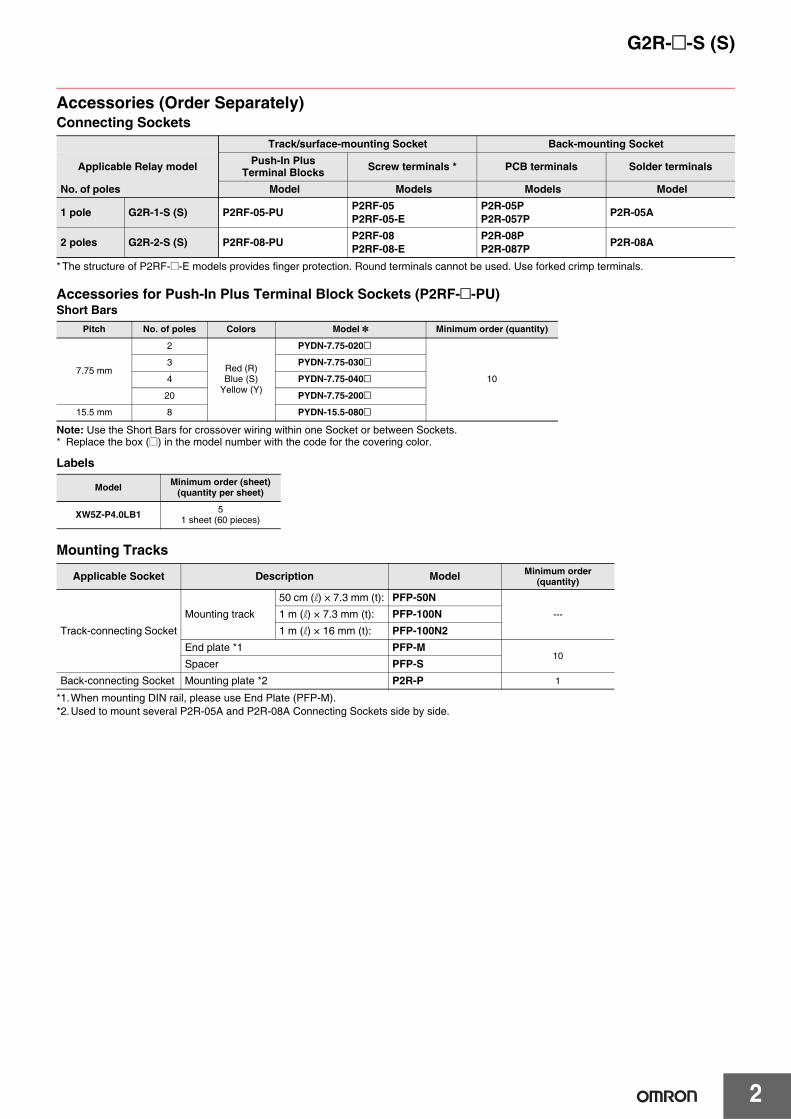
Accessories (Order Separately)Connecting Sockets
* The structure of P2RF-@-E models provides finger protection. Round terminals cannot be used. Use forked crimp terminals.
Accessories for Push-In Plus Terminal Block Sockets (P2RF-@-PU)Short Bars
Note: Use the Short Bars for crossover wiring within one Socket or between Sockets.* Replace the box (@) in the model number with the code for the covering color.
Labels
Mounting Tracks
*1.When mounting DIN rail, please use End Plate (PFP-M).*2.Used to mount several P2R-05A and P2R-08A Connecting Sockets side by side.
Track/surface-mounting Socket Back-mounting Socket
Applicable Relay model Push-In Plus Terminal Blocks Screw terminals * PCB terminals Solder terminals
No. of poles Model Models Models Model
1 pole G2R-1-S (S) P2RF-05-PU P2RF-05P2RF-05-E
P2R-05PP2R-057P P2R-05A
2 poles G2R-2-S (S) P2RF-08-PU P2RF-08P2RF-08-E
P2R-08PP2R-087P P2R-08A
Pitch No. of poles Colors Model * Minimum order (quantity)
7.75 mm
2
Red (R)Blue (S)
Yellow (Y)
PYDN-7.75-020@
10
3 PYDN-7.75-030@
4 PYDN-7.75-040@
20 PYDN-7.75-200@
15.5 mm 8 PYDN-15.5-080@
Model Minimum order (sheet)(quantity per sheet)
XW5Z-P4.0LB1 51 sheet (60 pieces)
Applicable Socket Description Model Minimum order (quantity)
Track-connecting Socket
Mounting track
50 cm (l) × 7.3 mm (t): PFP-50N---1 m (l) × 7.3 mm (t): PFP-100N
1 m (l) × 16 mm (t): PFP-100N2End plate *1 PFP-M
10Spacer PFP-S
Back-connecting Socket Mounting plate *2 P2R-P 1

G2R-@-S (S)
3
SpecificationsCoil Ratings
Note: 1. The rated current and coil resistance are measured at a coil temperature of 23°C with tolerances of +15%/-20% for the AC rated current and ±10% for the DC coil resistance.
2. The AC coil resistance and inductance values are reference values only (at 60 Hz).3. Operating characteristics were measured at a coil temperature of 23°C.4. The maximum voltage is the maximum possible value of the voltage that can be applied to the relay coil.
It is not the maximum voltage that can be applied continuously.
Contact Ratings
Note: P level: λ60 = 0.1 x 10⁻⁶/operation* This value was measured at a switching frequency of 120 operations per minute.
Rated voltageRated current*
Coil resistance
Coil inductance (H) (ref. value)
Mustoperate voltage
Mustrelease voltage
Max.voltage Power
consumption (approx.)
50 Hz 60 Hz Armature OFF
Armature ON % of rated voltage
AC
24 V 43.5 mA 37.4 mA 253 Ω 0.81 1.55
80% max. 30% max. 110% 0.9 VA at 60 Hz
110 V 9.5 mA 8.2 mA 5,566 Ω 13.33 26.83
120 V 8.6 mA 7.5 mA 7,286 Ω 16.13 32.46
230 V 4.4 mA 3.8 mA 27,172 Ω 72.68 143.90
240 V 3.7 mA 3.2 mA 30,360 Ω 90.58 182.34
Rated voltage Rated current* Coil resistance
Coil inductance (H) (ref. value)
Mustoperate voltage
Mustrelease voltage
Max.voltage Power
consumption (approx.)Armature
OFFArmature
ON % of rated voltage
DC
6 V 87.0 mA 69 Ω 0.25 0.48
70% max. 15% min. 110% 0.53 W12 V 43.2 mA 278 Ω 0.98 2.35
24 V 21.6 mA 1,113 Ω 3.60 8.25
48 V 11.4 mA 4,220 Ω 15.2 29.82
Number of poles 1 pole 2 poles
Load Resistive load(cosφ = 1)
Inductive load(cosφ = 0.4; L/R = 7 ms)
Resistive load(cosφ = 1)
Inductive load(cosφ = 0.4; L/R = 7 ms)
Rated load 10 A at 250 VAC;10 A at 30 VDC
7.5 A at 250 VAC;5 A at 30 VDC
5 A at 250 VAC;5 A at 30 VDC
2 A at 250 VAC; 3 A at 30 VDC
Rated carry current 10 A 5 A
Max. switching voltage 440 VAC, 125 VDC 380 VAC, 125 VDC
Max. switching current 10 A 5 A
Max. switching power 2,500 VA,300 W
1,875 VA, 150 W
1,250 VA, 150 W
500 VA, 90 W
Failure rate (reference value) * 100 mA at 5 VDC 10 mA at 5 VDC

4
G2R-@-S (S)
Characteristics
Note: Values in the above table are the initial values.* These values are relay only. Prease refer to the “Products Related to Common Sockets and DIN Tracks Data Sheet” for connecting sockets.
Approved StandardsUL 508 (File No. E41643)
CSA 22.2 No.0, No.14 (File No. LR31928)
IEC/VDE (Certificate No. 40015012 EN 61810-1)
LR
Item 1 pole 2 polesContact configration SPDT
Contact structure Single
Contact resistance 100 mΩ max.
Operate (set) time 15 ms max.
Release (reset) time AC: 10 ms max.; DC: 5 ms max. (w/built-in diode: 20 ms max.)
AC: 15 ms max.; DC: 10 ms max. (w/built-in diode: 20 ms max.)
Max. operating frequency
Mechanical: 18,000 operations/hrElectrical: 1,800 operations/hr (under rated load)
Insulation resistance 1,000 MΩ min. (at 500 VDC)
Dielectric strength *
5,000 VAC, 50/60 Hz for 1 min between coil and contacts;1,000 VAC, 50/60 Hz for 1 min between contacts of same polarity
5,000 VAC, 50/60 Hz for 1 min between coil and contacts;3,000 VAC, 50/60 Hz for 1 min between contacts of different polarity1,000 VAC, 50/60 Hz for 1 min between contacts of same polarity
Vibration resistance Destruction: 10 to 55 to 10 Hz, 0.75 mm single amplitude (1.5 mm double amplitude)Malfunction: 10 to 55 to 10 Hz, 0.75 mm single amplitude (1.5 mm double amplitude)
Shock resistance Destruction: 1,000 m/s2
Malfunction: 200 m/s2 when energized; 100 m/s2 when not energized
EnduranceMechanical: AC coil: 10,000,000 operations min.;
DC coil: 20,000,000 operations min. (at 18,000 operations/hr)Electrical: 100,000 operations min. (at 1,800 operations/hr under rated load)
Ambient temperature Operating: –40°C to 70°C (with no icing or condensation)
Ambient humidity Operating: 5% to 85%
Weight Approx. 20 g
Model Contact form Coil ratings Contact ratings Opera-
tions
G2R-1-S (S) SPDT
5 to 110 VDC6 to 240 VAC
10 A, 30 VDC (resistive)10 A, 250 VAC (general use) 100 × 103
TV-3 (NO contact only) 25 × 103
G2R-2-S (S) DPDT5 A, 30 VDC (resistive)5 A, 250 VAC (general use) 100 × 103
TV-3 (NO contact only) 25 × 103
Contact form Coil ratings Contact ratings Operations
1 pole6, 12, 24, 48 VDC24, 110, 120, 230, 240 VAC
5 A, 440 VAC (cosφ = 1.0)10 A, 250 VAC (cosφ = 1.0)10 A, 30 VDC (0 ms)
100 × 103
2 poles6, 12, 24, 48 VDC24, 110, 120, 230, 240 VAC
5 A, 250 VAC (cosφ =1.0)5 A, 30 VDC (0 ms) 100 × 103
Number of poles Coil ratings Contact ratings Operations
1 pole 5 to 110 VDC6 to 240 VDC
10 A, 250 VAC (general use)7.5 A, 250 VAC (PF0.4)10 A, 30 VDC (resistive)5A, 30VDC (L/R=7ms)
100 × 103
2 poles 5 to 110 VDC6 to 240 VDC
5 A, 250 VAC (general use)2 A, 250 VAC (PF0.4)5 A, 30 VDC (resistive)3A, 30VDC (L/R=7ms)
100 × 103

G2R-@-S (S)
5
Engineering DataMaximum Switching Power
Endurance
Ambient Temperature vs Maximum Coil Voltage
100
10
1
0.11 10 100 1000
100
10
1
0.11 10 100 1000
G2R-1-S (S)
Sw
itchi
ng c
urre
nt (
A)
Switching voltage (V)
G2R-2-S (S)
Switching voltage (V)
Sw
itchi
ng c
urre
nt (
A)
AC inductive load (cosφ = 0.4) AC resistive
load
DC resistive load
DC inductive load (L/R = 7 ms)
AC inductive load (cosφ = 0.4)
AC resistive load
DC resistive load
DC inductive load (L/R = 7 ms)
5,000
1,000
500
100
50
5,000
1,000
500
100
50
10,000
G2R-1-S (S)
End
uran
ce (
x103
oper
atio
ns)
Switching current (A)
G2R-2-S (S)
Switching current (A)
30-VDC inductive load (L/R = 7ms)
30-VDC inductive load (L/R = 7ms)
End
uran
ce (
x103
oper
atio
ns)
250-VAC/30-VDCresistive load
250-VAC inductive load (cosφ = 0.4)
250-VAC/30-VDCresistive load
250-VAC inductive load (cosφ = 0.4)
Ambient temperature (°C)
Max
imum
vol
tage
(%
)
DC coil
AC coil

6
G2R-@-S (S)Dimensions (Unit: mm)
Note: All units are in millimeters unless otherwise indicated.
SPDT Relays
DPDT Relays
G2R-1-S (S), G2R-1-SN (S), G2R-1-SNI (S)G2R-1-SD (S), G2R-1-SND (S), G2R-1-SNDI (S)
Terminal Arrangement/Internal Connections (Bottom View)
1
2 345
DC24V
201
0.5 4.75
7.5
17.5
5.25.2
35.5
max
.
29 max. 13 max.
5
G2R-1-SND (S), G2R-1-SNDI (S) (DC)
G2R-1-S (S) G2R-1-SD (S) (DC)
G2R-1-SN (S), G2R-1-SNI (S) (AC) G2R-1-SN (S), G2R-1-SNI (S) (DC)
1
2 345 2 45
1
3
2 45
1
3
1
2 345
G2R-2-S (S), G2R-2-SN (S), G2R-2-SNI (S)G2R-2-SD (S), G2R-2-SND (S), G2R-2-SNDI (S)
Terminal Arrangement/Internal Connections (Bottom View)
G2R-2-SND (S), G2R-2-SNDI (S) (DC)
G2R-2-S (S) G2R-2-SD (S) (DC)
G2R-2-SN (S), G2R-2-SNI (S) (AC) G2R-2-SN (S), G2R-2-SNI (S) (DC)
20
0.5
55
2.5
2.4
19.4
29 max.
35.5
max
.
13 max.
6.2
7.4
8.9
1
8
2 3 4
7 6 5
2 3 4
567
1
8
2 3 4
7 6 5
1
8
2 3 4
7 6 5
1
8
1
8
2 3 4
7 6 5

G2R-@-S (S)
7
Track/Surface Mounting Sockets
Mounting Hole Dimensions
52.4
45
36.3
27.6
27.25
35.5
28.1
27.6
52.1
3.9
56.5 max.
15.5 max.
90 max.
(3)
(3)
Release lever
14
12
11
A1A2
Terminal Arrangement/Internal Connection Diagram
(Top View)
(5)
(2)
(4)
(3)
(1)
Two M4 screw holes ortwo 4-dia. holes
108
P2RF-05-PU
Note: Pull out the hooks to mount the Relay with screws.
Note: The numbers in parentheses are traditionally used terminal numbers.
Mounting Hole Dimensions
27.6
28.1
45
36.3
27.6
35.5
27.25
52.1
52.4
3.9
56.5 max.
15.5 max.
(3)
(3)
90 max. Release lever
14
22
24
21
12
11
A1A2
Terminal Arrangement/Internal Connection Diagram
(Top View)
(8)
(2)
(4)
(3)
(7)
(5)
(6)
(1)
Two M4 screw holes ortwo 4-dia. holes
108
P2RF-08-PU
Note: Pull out the hooks to mount the Relay with screws.Note: The numbers in
parentheses are traditionally used terminal numbers.
Accessories for P2RF-@-PUShort BarsPYDN-7.75-@@ (7.75 mm)
PYDN-15.5-080@ (15.5 mm)
3.90L
1.572.25
1218.5
3.90
1.572.25
1218.5
115.85
* Replace the box (@) in the model number with the code for the covering color.
Note: 1. Use the Short Bars for crossover wiring within one Socket or between Sockets.2. When using short bar to coil terminals of P2RF-@@-PU, A1 terminal cannot be used.
In case crossover wiring of A1 terminal side is needed, crossover wiring using A1 terminals by wire is possible.Short bar correspondence table
Application Pitch No. of poles L (Length) Colors Model * Maximum
carry current
For Contactterminals(common)
7.75 mm
2 15.1
Red (R)Blue (S)Yellow (Y)
PYDN-7.75-020@
20 A
3 22.85 PYDN-7.75-030@
4 30.6 PYDN-7.75-040@
20 154.6 PYDN-7.75-200@
For Coilterminals 15.5 mm 8 115.85 PYDN-15.5-080@
Contact terminal(Common)
Coil terminal
A1 A2
P2RF-@@-PU Available --- ❍

8
G2R-@-S (S)
39.5±0.1
P2RF-05
P2RF-08
7
4
2
35.5
19.5
30±0.05
7
4
2
35.5
19.5
30±0.05
P2RF-05-E
39.5
35.5
11.5
(11)
(14)(12)
(A1)(A2)
1
2
3
4
5
39.5±0.1
2 1.5
4
2
3
39.535.5
11.5
P2RF-08-E
8
6 3
7 2
5 4
(A1)
(A2)
(21)(22)(24)
(11)(12)(14)
1
2
3.2-dia. hole
Five, M3.5 x 8
19.5 max.
4-dia. holes
30 max.
54 max.
4.2-dia. hole
71.5 max.
19.5 max.
Eight, M3.5 x 8
4-dia. holes
30 max.
54 max.
4.2-dia. hole
3.2-dia. hole
Five, M3.5´7
85.5 max.
16.0 max.
48 max.
Note: Pin numbers in parentheses apply to DIN standard.61 max.
Eight, M3´8
3.5-dia. hole
16.0 max.
48.0 max.
61.0 max.
Terminal Arrangement(Top View)
Mounting Holes(for Surface Mounting)
Terminal Arrangement(Top View)
Mounting Holes(for Surface Mounting)
M3 or 3.5-dia. hole
M3 or 3.5-dia. hole
3.5-dia. hole
85.5 max.
M3 or 3.2-dia. hole
M3 or 3.2-dia. hole
Terminal Arrangement(Top View)
Mounting Holes(for Surface Mounting)
Terminal Arrangement(Top View)
Mounting Holes(for Surface Mounting)
71.5 max.
4
7±0.2
6+0.2−0.1

G2R-@-S (S)
9
Mounting Height of Relay with Track/Surface Mounting Sockets
Back-connecting Sockets
P2RF-@ P2RF-@-E
P2RF-05-PU P2RF-08-PU
G2R-@-S (S) Relay
G2R-@-S (S) Relay
P2RF-@-E Socket
P2RF Socket
66.5 62.0 67.0 70.5
G2R-@-S (S) Relay
G2R-@-S (S) Relay
63.6
28.1
(3.9)
63.6
28.1
(3.9)
1 4 7
6
4.5
15
43.5
1.2
1.5
7 4
4
6
4.5
15
4
7
47
0.3
5
5
201
2.8
1.5
7.5
7.5
5
5
20
(4.3)
(5)
P2R-05P (1-pole)14.5 max.
35.5 max.
Tolerance: ±0.1
Mounting Holes
P2R-08P (2-pole)
36.5 max.Terminal plate thickness: 0.3
14.5 max.
35.5 max.
Eight, 1.3-dia. holes
Terminal Arrangement (Bottom View)
Mounting HolesTerminal Arrangement (Bottom View)
Five, 1.6-dia. holes
36.5 max.

10
G2R-@-S (S)
Mounting Height of Relay with Back-connecting Sockets
4.5
1.20.3
6.7
3.8
16.7 5
6
1.20.3
5
5
20
2.8
2.6
7.5
13.6±0.1
30.5±0.2
1.5
7.5
7.56.5
P2R-05A (1-pole)
Panel Cutout
P2R-08A (2-pole)
Five, 3 x 1.8-dia. holes
36.5 max.Terminal plate thickness: 0.3
14.5 max.
35.5 max.
36.5 max.Terminal plate thickness: 0.3
14.5 max.
35.5 max.
Eight, 3 x 1.2-dia. holes
Terminal Arrangement(Bottom View)
Recommended thickness of the panel is 1.6 to 2.0 mm
P2R-057P (1-pole)
P2R-087P (2-pole)
4.5±0.1 15±0.1
4±0.15
4±0.1
6±0.1
7±0.1
7.5
55
20
(8.1)
29.6
0.7
8.9
8.7
8.7
29.1
7.5
14 max.
37 max.
14 max.
37 max.
41 max.
Mounting HolesTerminal Arrangement(Bottom View)
Mounting HolesTerminal Arrangement(Bottom View)
Eight, 1.3-dia. holes
Five, 1.6-dia. holes
7.4
1
0.3
16.4
110.4 3.5
5
20
8.1
5
16.4
110.4
1
1
7.4
41 max.
3.5
6
15
48.75
4.5
38.0
P2R-@7P
G2R-@-S (S) Relay
P2R-@P Socket P2R-@A
Socket
G2R-@-S (S) Relay
P2R-@7P Socket
G2R-@-S (S) Relay
P2R-@P P2R-@A
47.544.5

G2R-@-S (S)
11
Mounting Tracks
End Plate Spacer
Mounting Plate
P2R-P
Safety PrecautionsBe sure to read the Common Precautions for All Relay in the website at the following URL: http://www.ia.omron.com/.Refer to Products Related to Common Sockets and DIN Tracks for precautions on the applicable Sockets.Refer to PYF-@@-PU/P2RF-@@-PU for precautions on Push-In Plus Terminal Block Sockets.Warning Indications
• Do not use the test button for any purpose other than testing. Be sure not to touch the test button accidentally as this will turn the contacts ON. Before using the test button, confirm that circuits, the load, and any other connected item will operate safely.
• Check that the test button is released before turning ON relay cir-cuits.
• If the test button is pulled out too forcefully, it may bypass the mo-mentary testing position and go straight into the locked position.
• Use an insulated tool when you operate the test button.
PFP-100N, PFP-50N PFP-100N2
4.5
15 25 25 25 2510 10
1,000 (500)
7.3±0.15
35±0.3 27±0.15
1
4.5
15 25 25 25 25 1510 10
1,000
35±0.3 27 24
16
29.2
1 1.515 (5)
It is recommended to use a panel 1.6 to 2.0 mm thick.
PFP-M PFP-S
50
11.5
106.2
1.8
135.5 35.3
1.8
1.3
4.8
5
1612
44.3 34.8
10
16.5M4 x 8 pan head screw
904.5
49 42±0.1
9±0.1 9±0.1
18±0.15 18±0.15 18±0.15
72±0.2
18±0.15
R2.2510-Ellipse hole
13.6
Square hole
3.4
30.5
t=1.6 mm
CAUTIONIndicates a potentially hazardous situation which, if not avoided, may result in minor or moderate injury or in property damage.
Cation

Terms and Conditions of Sale1. Offer; Acceptance. These terms and conditions (these "Terms") are deemed
part of all quotes, agreements, purchase orders, acknowledgments, price lists,catalogs, manuals, brochures and other documents, whether electronic or inwriting, relating to the sale of products or services (collectively, the "Products")by Omron Electronics LLC and its subsidiary companies (“Omron”). Omronobjects to any terms or conditions proposed in Buyer’s purchase order or otherdocuments which are inconsistent with, or in addition to, these Terms.
2. Prices; Payment Terms. All prices stated are current, subject to change with-out notice by Omron. Omron reserves the right to increase or decrease priceson any unshipped portions of outstanding orders. Payments for Products aredue net 30 days unless otherwise stated in the invoice.
3. Discounts. Cash discounts, if any, will apply only on the net amount of invoicessent to Buyer after deducting transportation charges, taxes and duties, and willbe allowed only if (i) the invoice is paid according to Omron’s payment termsand (ii) Buyer has no past due amounts.
4. Interest. Omron, at its option, may charge Buyer 1-1/2% interest per month orthe maximum legal rate, whichever is less, on any balance not paid within thestated terms.
5. Orders. Omron will accept no order less than $200 net billing. 6. Governmental Approvals. Buyer shall be responsible for, and shall bear all
costs involved in, obtaining any government approvals required for the impor-tation or sale of the Products.
7. Taxes. All taxes, duties and other governmental charges (other than generalreal property and income taxes), including any interest or penalties thereon,imposed directly or indirectly on Omron or required to be collected directly orindirectly by Omron for the manufacture, production, sale, delivery, importa-tion, consumption or use of the Products sold hereunder (including customsduties and sales, excise, use, turnover and license taxes) shall be charged toand remitted by Buyer to Omron.
8. Financial. If the financial position of Buyer at any time becomes unsatisfactoryto Omron, Omron reserves the right to stop shipments or require satisfactorysecurity or payment in advance. If Buyer fails to make payment or otherwisecomply with these Terms or any related agreement, Omron may (without liabil-ity and in addition to other remedies) cancel any unshipped portion of Prod-ucts sold hereunder and stop any Products in transit until Buyer pays allamounts, including amounts payable hereunder, whether or not then due,which are owing to it by Buyer. Buyer shall in any event remain liable for allunpaid accounts.
9. Cancellation; Etc. Orders are not subject to rescheduling or cancellationunless Buyer indemnifies Omron against all related costs or expenses.
10. Force Majeure. Omron shall not be liable for any delay or failure in deliveryresulting from causes beyond its control, including earthquakes, fires, floods,strikes or other labor disputes, shortage of labor or materials, accidents tomachinery, acts of sabotage, riots, delay in or lack of transportation or therequirements of any government authority.
11. Shipping; Delivery. Unless otherwise expressly agreed in writing by Omron:a. Shipments shall be by a carrier selected by Omron; Omron will not drop ship
except in “break down” situations.b. Such carrier shall act as the agent of Buyer and delivery to such carrier shall
constitute delivery to Buyer;c. All sales and shipments of Products shall be FOB shipping point (unless oth-
erwise stated in writing by Omron), at which point title and risk of loss shallpass from Omron to Buyer; provided that Omron shall retain a security inter-est in the Products until the full purchase price is paid;
d. Delivery and shipping dates are estimates only; ande. Omron will package Products as it deems proper for protection against nor-
mal handling and extra charges apply to special conditions.12. Claims. Any claim by Buyer against Omron for shortage or damage to the
Products occurring before delivery to the carrier must be presented in writingto Omron within 30 days of receipt of shipment and include the original trans-portation bill signed by the carrier noting that the carrier received the Productsfrom Omron in the condition claimed.
13. Warranties. (a) Exclusive Warranty. Omron’s exclusive warranty is that theProducts will be free from defects in materials and workmanship for a period oftwelve months from the date of sale by Omron (or such other period expressedin writing by Omron). Omron disclaims all other warranties, express or implied.(b) Limitations. OMRON MAKES NO WARRANTY OR REPRESENTATION,EXPRESS OR IMPLIED, ABOUT NON-INFRINGEMENT, MERCHANTABIL-
ITY OR FITNESS FOR A PARTICULAR PURPOSE OF THE PRODUCTS.BUYER ACKNOWLEDGES THAT IT ALONE HAS DETERMINED THAT THEPRODUCTS WILL SUITABLY MEET THE REQUIREMENTS OF THEIRINTENDED USE. Omron further disclaims all warranties and responsibility ofany type for claims or expenses based on infringement by the Products or oth-erwise of any intellectual property right. (c) Buyer Remedy. Omron’s sole obli-gation hereunder shall be, at Omron’s election, to (i) replace (in the formoriginally shipped with Buyer responsible for labor charges for removal orreplacement thereof) the non-complying Product, (ii) repair the non-complyingProduct, or (iii) repay or credit Buyer an amount equal to the purchase price ofthe non-complying Product; provided that in no event shall Omron be responsi-ble for warranty, repair, indemnity or any other claims or expenses regardingthe Products unless Omron’s analysis confirms that the Products were prop-erly handled, stored, installed and maintained and not subject to contamina-tion, abuse, misuse or inappropriate modification. Return of any Products byBuyer must be approved in writing by Omron before shipment. Omron Compa-nies shall not be liable for the suitability or unsuitability or the results from theuse of Products in combination with any electrical or electronic components,circuits, system assemblies or any other materials or substances or environ-ments. Any advice, recommendations or information given orally or in writing,are not to be construed as an amendment or addition to the above warranty.See http://www.omron247.com or contact your Omron representative for pub-lished information.
14. Limitation on Liability; Etc. OMRON COMPANIES SHALL NOT BE LIABLEFOR SPECIAL, INDIRECT, INCIDENTAL, OR CONSEQUENTIAL DAMAGES,LOSS OF PROFITS OR PRODUCTION OR COMMERCIAL LOSS IN ANYWAY CONNECTED WITH THE PRODUCTS, WHETHER SUCH CLAIM ISBASED IN CONTRACT, WARRANTY, NEGLIGENCE OR STRICT LIABILITY.Further, in no event shall liability of Omron Companies exceed the individualprice of the Product on which liability is asserted.
15. Indemnities. Buyer shall indemnify and hold harmless Omron Companies andtheir employees from and against all liabilities, losses, claims, costs andexpenses (including attorney's fees and expenses) related to any claim, inves-tigation, litigation or proceeding (whether or not Omron is a party) which arisesor is alleged to arise from Buyer's acts or omissions under these Terms or inany way with respect to the Products. Without limiting the foregoing, Buyer (atits own expense) shall indemnify and hold harmless Omron and defend or set-tle any action brought against such Companies to the extent based on a claimthat any Product made to Buyer specifications infringed intellectual propertyrights of another party.
16. Property; Confidentiality. Any intellectual property in the Products is the exclu-sive property of Omron Companies and Buyer shall not attempt to duplicate itin any way without the written permission of Omron. Notwithstanding anycharges to Buyer for engineering or tooling, all engineering and tooling shallremain the exclusive property of Omron. All information and materials suppliedby Omron to Buyer relating to the Products are confidential and proprietary,and Buyer shall limit distribution thereof to its trusted employees and strictlyprevent disclosure to any third party.
17. Export Controls. Buyer shall comply with all applicable laws, regulations andlicenses regarding (i) export of products or information; (iii) sale of products to“forbidden” or other proscribed persons; and (ii) disclosure to non-citizens ofregulated technology or information.
18. Miscellaneous. (a) Waiver. No failure or delay by Omron in exercising any rightand no course of dealing between Buyer and Omron shall operate as a waiverof rights by Omron. (b) Assignment. Buyer may not assign its rights hereunderwithout Omron's written consent. (c) Law. These Terms are governed by thelaw of the jurisdiction of the home office of the Omron company from whichBuyer is purchasing the Products (without regard to conflict of law princi-ples). (d) Amendment. These Terms constitute the entire agreement betweenBuyer and Omron relating to the Products, and no provision may be changedor waived unless in writing signed by the parties. (e) Severability. If any provi-sion hereof is rendered ineffective or invalid, such provision shall not invalidateany other provision. (f) Setoff. Buyer shall have no right to set off any amountsagainst the amount owing in respect of this invoice. (g) Definitions. As usedherein, “including” means “including without limitation”; and “Omron Compa-nies” (or similar words) mean Omron Corporation and any direct or indirectsubsidiary or affiliate thereof.
Certain Precautions on Specifications and Use1. Suitability of Use. Omron Companies shall not be responsible for conformity
with any standards, codes or regulations which apply to the combination of theProduct in the Buyer’s application or use of the Product. At Buyer’s request,Omron will provide applicable third party certification documents identifyingratings and limitations of use which apply to the Product. This information byitself is not sufficient for a complete determination of the suitability of the Prod-uct in combination with the end product, machine, system, or other applicationor use. Buyer shall be solely responsible for determining appropriateness ofthe particular Product with respect to Buyer’s application, product or system.Buyer shall take application responsibility in all cases but the following is anon-exhaustive list of applications for which particular attention must be given:(i) Outdoor use, uses involving potential chemical contamination or electricalinterference, or conditions or uses not described in this document.(ii) Use in consumer products or any use in significant quantities. (iii) Energy control systems, combustion systems, railroad systems, aviationsystems, medical equipment, amusement machines, vehicles, safety equip-ment, and installations subject to separate industry or government regulations. (iv) Systems, machines and equipment that could present a risk to life or prop-erty. Please know and observe all prohibitions of use applicable to this Prod-uct. NEVER USE THE PRODUCT FOR AN APPLICATION INVOLVING SERIOUSRISK TO LIFE OR PROPERTY OR IN LARGE QUANTITIES WITHOUTENSURING THAT THE SYSTEM AS A WHOLE HAS BEEN DESIGNED TO
ADDRESS THE RISKS, AND THAT THE OMRON’S PRODUCT IS PROP-ERLY RATED AND INSTALLED FOR THE INTENDED USE WITHIN THEOVERALL EQUIPMENT OR SYSTEM.
2. Programmable Products. Omron Companies shall not be responsible for theuser’s programming of a programmable Product, or any consequence thereof.
3. Performance Data. Data presented in Omron Company websites, catalogsand other materials is provided as a guide for the user in determining suitabil-ity and does not constitute a warranty. It may represent the result of Omron’stest conditions, and the user must correlate it to actual application require-ments. Actual performance is subject to the Omron’s Warranty and Limitationsof Liability.
4. Change in Specifications. Product specifications and accessories may bechanged at any time based on improvements and other reasons. It is our prac-tice to change part numbers when published ratings or features are changed,or when significant construction changes are made. However, some specifica-tions of the Product may be changed without any notice. When in doubt, spe-cial part numbers may be assigned to fix or establish key specifications foryour application. Please consult with your Omron’s representative at any timeto confirm actual specifications of purchased Product.
5. Errors and Omissions. Information presented by Omron Companies has beenchecked and is believed to be accurate; however, no responsibility is assumedfor clerical, typographical or proofreading errors or omissions.

OMRON CANADA, INC. • HEAD OFFICEToronto, ON, Canada • 416.286.6465 • 866.986.6766 • www.omron247.com
OMRON ELECTRONICS DE MEXICO • HEAD OFFICEMéxico DF • 52.55.59.01.43.00 • 01-800-226-6766 • [email protected]
OMRON ELECTRONICS DE MEXICO • SALES OFFICEApodaca, N.L. • 52.81.11.56.99.20 • 01-800-226-6766 • [email protected]
OMRON ELETRÔNICA DO BRASIL LTDA • HEAD OFFICESão Paulo, SP, Brasil • 55.11.2101.6300 • www.omron.com.br
OMRON ARGENTINA • SALES OFFICECono Sur • 54.11.4783.5300
OMRON CHILE • SALES OFFICESantiago • 56.9.9917.3920
OTHER OMRON LATIN AMERICA SALES54.11.4783.5300
Authorized Distributor:
J140I-E-02 04/16 Note: Specifications are subject to change. © 2016 Omron. All Rights Reserved. Printed in U.S.A.
Printed on recycled paper.
OMRON AUTOMATION AMERICAS HEADQUARTERS • Chicago, IL USA • 847.843.7900 • 800.556.6766 • www.omron247.com
OMRON EUROPE B.V. • Wegalaan 67-69, NL-2132 JD, Hoofddorp, The Netherlands. • +31 (0) 23 568 13 00 • www.industrial.omron.eu
Controllers & I/O • Machine Automation Controllers (MAC) • Motion Controllers • Programmable Logic Controllers (PLC) • Temperature Controllers • Remote I/O
Robotics • Industrial Robots • Mobile Robots
Operator Interfaces• Human Machine Interface (HMI)
Motion & Drives• Machine Automation Controllers (MAC) • Motion Controllers • Servo Systems • Frequency Inverters
Vision, Measurement & Identification• Vision Sensors & Systems • Measurement Sensors • Auto Identification Systems
Sensing• Photoelectric Sensors • Fiber-Optic Sensors • Proximity Sensors • Rotary Encoders • Ultrasonic Sensors
Safety • Safety Light Curtains • Safety Laser Scanners • Programmable Safety Systems • Safety Mats and Edges • Safety Door Switches • Emergency Stop Devices • Safety Switches & Operator Controls • Safety Monitoring/Force-guided Relays
Control Components • Power Supplies • Timers • Counters • Programmable Relays • Digital Panel Meters • Monitoring Products
Switches & Relays • Limit Switches • Pushbutton Switches • Electromechanical Relays • Solid State Relays
Software • Programming & Configuration • Runtime