general purpose control system for scanning laser ophthalmoscopes
TRANSCRIPT
Clinical and Experimental Ophthalmology
2003;
31
: 241–245
Clinical and Epidemiological
______________________
Clinical and Epidemiology
General purpose control system for scanning laser ophthalmoscopes
John Cushion
BSc MIEE CEng
, Fred N Reinholz
PhD
and Brett A Patterson
PhD MInstP CPhys
Lions Eye Institute of Western Australia and Centre for Ophthalmology and Visual Science, University of Western Australia, Perth, Western Australia, Australia
A
BSTRACT
A flexible control system for scanning laser ophthalmoscopesis described that is quick and simple to configure, easilymodified or adapted, and containing many useful features.The system facilitates adjustment of several parameters toaccount for changes to the scan position, ambient light andtemperature, including both optical and electronic compo-nents, which is otherwise difficult and time-consuming toperform. The system is portable and uses custom-designedprinted circuit boards. All system parameters, such as focus,scan rate, scan depth and stereo control can be digitallycontrolled from a computer via a single serial port. Customsoftware allows changes to any system parameters by simplysending the required control data to the rack. The circuitboards in the system are multilayer, incorporating goodground-plane techniques to minimize noise, programmablelogic and semicustom logic for low cost and compact size,and microcontrollers with embedded firmware for flexibleoperation. Retinal images demonstrate that the system per-forms well.
Key words:
laser scanning, ophthalmic instrumentation,scanning laser ophthalmoscope.
I
NTRODUCTION
Scanning laser ophthalmoscopes (SLO) consist of one ormore laser light sources, a collection of mirrors and optics todeflect and scan the laser, a detection system to capture thereflected light and some electronics to perform the neces-sary control and signal capture.
1
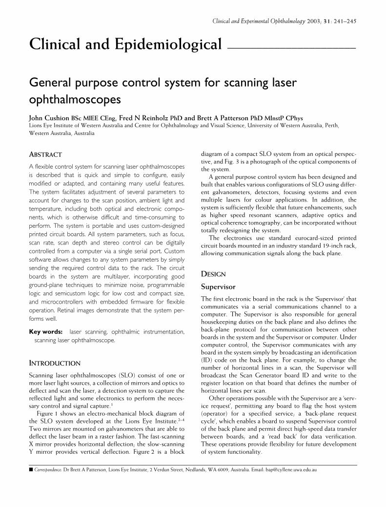
Figure 1 shows an electro-mechanical block diagram ofthe SLO system developed at the Lions Eye Institute.
2–4
Two mirrors are mounted on galvanometers that are able todeflect the laser beam in a raster fashion. The fast-scanningX mirror provides horizontal deflection; the slow-scanningY mirror provides vertical deflection. Figure 2 is a block
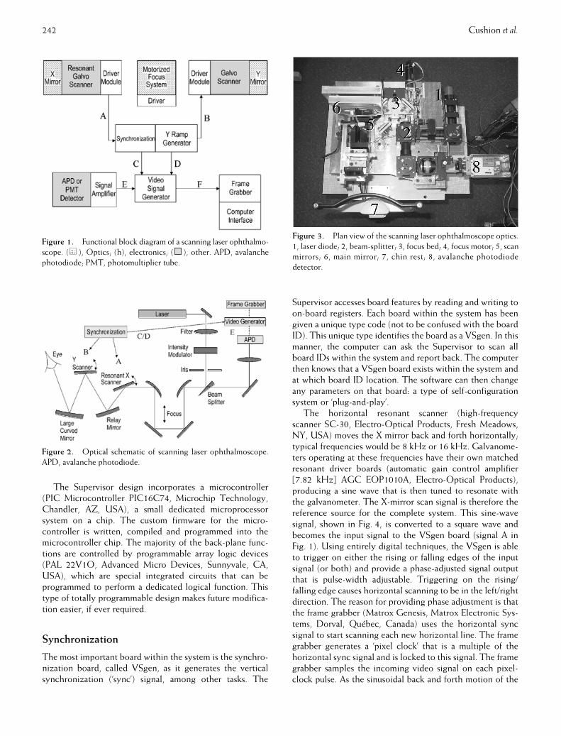
diagram of a compact SLO system from an optical perspec-tive, and Fig. 3 is a photograph of the optical components ofthe system.
A general purpose control system has been designed andbuilt that enables various configurations of SLO using differ-ent galvanometers, detectors, focusing systems and evenmultiple lasers for colour applications. In addition, thesystem is sufficiently flexible that future enhancements, suchas higher speed resonant scanners, adaptive optics andoptical coherence tomography, can be incorporated withouttotally redesigning the system.
The electronics use standard eurocard-sized printedcircuit boards mounted in an industry standard 19-inch rack,allowing communication signals along the back plane.
D
ESIGN
Supervisor
The first electronic board in the rack is the ‘Supervisor’ thatcommunicates via a serial communications channel to acomputer. The Supervisor is also responsible for generalhousekeeping duties on the back plane and also defines theback-plane protocol for communication between otherboards in the system and the Supervisor or computer. Undercomputer control, the Supervisor communicates with anyboard in the system simply by broadcasting an identification(ID) code on the back plane. For example, to change thenumber of horizontal lines in a scan, the Supervisor willbroadcast the Scan Generator board ID and write to theregister location on that board that defines the number ofhorizontal lines per scan.
Other operations possible with the Supervisor are a ‘serv-ice request’, permitting any board to flag the host system(operator) for a specified service; a ‘back-plane requestcycle’, which enables a board to suspend Supervisor controlof the back plane and permit direct high-speed data transferbetween boards; and a ‘read back’ for data verification.These operations provide flexibility for future developmentof system functionality.
�
Correspondence:
Dr Brett A Patterson, Lions Eye Institute, 2 Verdun Street, Nedlands, WA 6009, Australia. Email: [email protected]
242 Cushion
et al.
The Supervisor design incorporates a microcontroller(PIC Microcontroller PIC16C74, Microchip Technology,Chandler, AZ, USA), a small dedicated microprocessorsystem on a chip. The custom firmware for the micro-controller is written, compiled and programmed into themicrocontroller chip. The majority of the back-plane func-tions are controlled by programmable array logic devices(PAL 22V1O, Advanced Micro Devices, Sunnyvale, CA,USA), which are special integrated circuits that can beprogrammed to perform a dedicated logical function. Thistype of totally programmable design makes future modifica-tion easier, if ever required.
Synchronization
The most important board within the system is the synchro-nization board, called VSgen, as it generates the verticalsynchronization (‘sync’) signal, among other tasks. The
Supervisor accesses board features by reading and writing toon-board registers. Each board within the system has beengiven a unique type code (not to be confused with the boardID). This unique type identifies the board as a VSgen. In thismanner, the computer can ask the Supervisor to scan allboard IDs within the system and report back. The computerthen knows that a VSgen board exists within the system andat which board ID location. The software can then changeany parameters on that board: a type of self-configurationsystem or ‘plug-and-play’.
The horizontal resonant scanner (high-frequencyscanner SC-30, Electro-Optical Products, Fresh Meadows,NY, USA) moves the X mirror back and forth horizontally;typical frequencies would be 8 kHz or 16 kHz. Galvanome-ters operating at these frequencies have their own matchedresonant driver boards (automatic gain control amplifier[7.82 kHz] AGC EOP1010A, Electro-Optical Products),producing a sine wave that is then tuned to resonate withthe galvanometer. The X-mirror scan signal is therefore thereference source for the complete system. This sine-wavesignal, shown in Fig. 4, is converted to a square wave andbecomes the input signal to the VSgen board (signal A inFig. 1). Using entirely digital techniques, the VSgen is ableto trigger on either the rising or falling edges of the inputsignal (or both) and provide a phase-adjusted signal outputthat is pulse-width adjustable. Triggering on the rising/falling edge causes horizontal scanning to be in the left/rightdirection. The reason for providing phase adjustment is thatthe frame grabber (Matrox Genesis, Matrox Electronic Sys-tems, Dorval, Québec, Canada) uses the horizontal syncsignal to start scanning each new horizontal line. The framegrabber generates a ‘pixel clock’ that is a multiple of thehorizontal sync signal and is locked to this signal. The framegrabber samples the incoming video signal on each pixel-clock pulse. As the sinusoidal back and forth motion of the
Figure 1.
Functional block diagram of a scanning laser ophthalmo-scope. ( ), Optics; (h), electronics; ( ), other. APD, avalanchephotodiode; PMT, photomultiplier tube.
Figure 2.
Optical schematic of scanning laser ophthalmoscope.APD, avalanche photodiode.
Figure 3.
Plan view of the scanning laser ophthalmoscope optics.1, laser diode; 2, beam-splitter; 3, focus bed; 4, focus motor; 5, scanmirrors; 6, main mirror; 7, chin rest; 8, avalanche photodiodedetector.
SLO control system 243
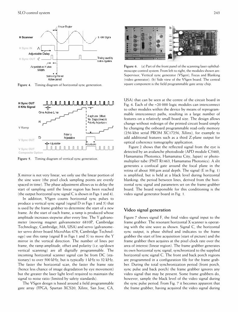
X mirror is not very linear, we only use the linear portion ofthe sine wave (the pixel clock sampling points are evenlyspaced in time). The phase adjustment allows us to delay thestart of sampling until the linear region has been reached(the output horizontal sync signal C is shown in Figs 1 and 4).
In addition, VSgen counts horizontal sync pulses toproduce a vertical sync signal (signal D in Figs 1 and 5) thatis used by the frame grabber to determine the start of a newframe. At the start of each frame, a ramp is produced whoseamplitude increases stepwise after every line. The Y galvano-meter (moving magnet galvanometer 6810P, CambridgeTechnology, Cambridge, MA, USA) and servo (galvanome-ter servo driver board MicroMax 678, Cambridge Technol-ogy) use this ramp (signal B in Figs 1 and 5) to move the Ymirror in the vertical direction. The number of lines perframe, the ramp amplitude, offset and polarity (i.e. up/downvertical scanning) are all digitally programmable. Theincoming horizontal scanner signal can be from DC (sta-tionary) to over 500 kHz, but is typically 1 kHz to 32 kHz.The faster the horizontal scan, the faster the frame rate(hence less chance of image degradation by eye movement)but the greater the laser light level required to maintain thesignal to noise ratio (limited by safety standards).
The VSgen design is based around a field programmablegate array (FPGA; Spartan XCS20, Xilinx, San Jose, CA,
USA) that can be seen at the centre of the circuit board inFig. 6. Each of the
∼
20 000 logic modules can interconnectto other modules within the device by means of reprogram-mable interconnect paths, resulting in a large number offeatures on a relatively small board size. The design allowschange without redesign of the printed circuit board simplyby changing the onboard programmable read-only memory(256-kbit serial PROM XC17256, Xilinx), for example toadd additional features such as a third Z-plane output foroptical coherence tomography application.
Figure 2 shows that the reflected signal from the eye isdetected by an avalanche photodiode (APD module C5460,Hamamatsu Photonics, Hamamatsu City, Japan) or photo-multiplier tube (PMT R1463, Hamamatsu Photonics). A slitgenerates a confocal gate around the focal plane in theretina of about 300
µ
m axial depth. The signal (E in Fig. 1)is amplified, but is held at a black level during horizontalblanking: the period between lines, derived from the hori-zontal sync signal and parameters set on the frame-grabberboard. The board responsible for this conditioning is thevideo signal generator board in Fig. 1.
Video signal generation
Figure 7 shows signal F, the final video signal input to theframe grabber. The resonant horizontal X scanner is operat-ing with the sine wave as shown. Signal C, the horizontalsync output, is phase shifted and indicates to the framegrabber the start of line acquisition (start of picture) and theframe grabber then acquires at the pixel clock rate over thearea of interest (linear region). The frame grabber generatesits own horizontal sync signal, synchronized to the suppliedhorizontal sync signal C. The front and back porch regionsare programmed in a configuration file for the frame grab-ber. During the total synchronization period (front porch,sync pulse and back porch) the frame grabber ignores anyvideo signal that may be present. Some frame grabbers do,however, sample the black level of the video signal duringthe sync pulse period. From Fig. 7 it becomes apparent thatthe frame grabber, having acquired the video signal during
Figure 4.
Timing diagram of horizontal sync generation.
Figure 5.
Timing diagram of vertical sync generation.
Figure 6.
(a) Part of the front panel of the scanning laser ophthal-moscope control system. From left to right, the modules shown are:Supervisor, Vertical sync generator (VSgen), Focus and Blanking(video generator). (b) Side view of the VSgen board. The centralsquare component is the field programmable gate array chip.
244 Cushion
et al.
the active region, will then wait during the inactive periodfor the next line (next horizontal sync pulse) before startingto acquire.
Focus and stereo
Figure 1 shows that the SLO system at the Lions Eye Insti-tute incorporates a focus bed that moves a pair of mirrors asshown in Fig. 2. Another board within the system achievesthis, the Focus board. This board drives a motor fitted witha planetary gearhead and a digital encoder (Part 110393,Maxon Precision Motors, Burlingame, CA, USA). Theencoder provides two pulses, channel A and B that are 90-degree phase shifted and provide angular velocity and direc-tion information. The Focus board decodes these signals todetermine the exact motor shaft position. Via software, theuser is able to repeatedly move the focus mirror bed to anyposition with micron resolution.
In addition, the focus board also provides stereo imagingcapability. Two galvanometer mirrors (25
°
closed-loop gal-vanometer scanner MG325DT, GSI Lumonics, Billerica,MA, USA) and servo drivers (closed-loop galvanometerservo driver AE1000, GSI Lumonics) are used to deflect thelaser to either side of the pupil (one fitted just before the Xresonant scanner, the other just after the Y scanner; Fig. 2).By moving these galvanometer mirrors prior to the start ofeach new frame we achieve two images offset by a smalldistance: the stereo base. The angle at which the galvano-meters deflect the laser is controlled by a demand signalprovided by the focus board and used by the galvanometerdriver board. All parameters are digitally adjustable so thatthe board does not depend upon a single type or make ofgalvanometer driver board. To generate a 3-D image, ananaglyph is formed using the red and green video memoriesof the frame grabber. Red and green coloured ‘3-D’ glassesthen make the retinal image appear in 3-D.
2
The Focus board incorporates both features: focus and3-D imaging. These features are implemented using an onboard FPGA (in a similar fashion to the VSgen board).Functionality can therefore be changed without redesign ofthe printed circuit board.
R
ESULTS
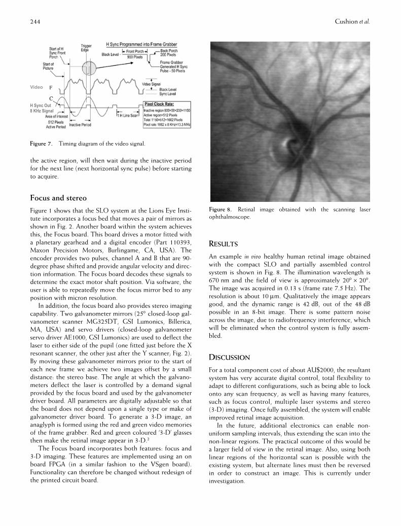
An example
in vivo
healthy human retinal image obtainedwith the compact SLO and partially assembled controlsystem is shown in Fig. 8. The illumination wavelength is670 nm and the field of view is approximately 20
°
×
20
°
.The image was acquired in 0.13 s (frame rate 7.5 Hz). Theresolution is about 10
µ
m. Qualitatively the image appearsgood, and the dynamic range is 42 dB, out of the 48 dBpossible in an 8-bit image. There is some pattern noiseacross the image, due to radiofrequency interference, whichwill be eliminated when the control system is fully assem-bled.
D
ISCUSSION
For a total component cost of about AU$2000, the resultantsystem has very accurate digital control, total flexibility toadapt to different configurations, such as being able to lockonto any scan frequency, as well as having many features,such as focus control, multiple laser systems and stereo(3-D) imaging. Once fully assembled, the system will enableimproved retinal image acquisition.
In the future, additional electronics can enable non-uniform sampling intervals, thus extending the scan into thenon-linear regions. The practical outcome of this would bea larger field of view in the retinal image. Also, using bothlinear regions of the horizontal scan is possible with theexisting system, but alternate lines must then be reversedin order to construct an image. This is currently underinvestigation.
Figure 7.
Timing diagram of the video signal.
Figure 8.
Retinal image obtained with the scanning laserophthalmoscope.

SLO control system 245
A
CKNOWLEDGEMENT
The authors thank John Barnett for providing excellentmechanical engineering work throughout the duration ofthe project.
R
EFERENCES
1. Webb RH, Hughes GW.
IEEE Trans Biomed Eng
1981;
28
: 488–92.2. Reinholz F
et al.
Development of a versatile stereo scanninglaser ophthalmoscope. In:
EUROPTO Conference on Lasers inOphthalmology,
1998
. Stockholm: SPIE, 1998; 138–44.3. Reinholz F
et al.
Cytometry
1999;
37
: 165–70.4. Ashman RA
et al.
Lasers Med Sci
2001;
16
: 52–9.