general principles of radiology 1 in endodontics
TRANSCRIPT
Endodontic Radiology, Second Edition. Edited by Bettina Basrani.© 2012 John Wiley & Sons, Inc. Published 2012 by John Wiley & Sons, Inc.
5
1 General Principles of Radiology in Endodontics
Anda Kfi r and Bettina Basrani
“ . . . And God said: Let there be light. And there was light. And God saw the light, which it was good; and God divided the light from the dark-ness . . . ” (Genesis 1:3 – 4, The Bible, King James version)
Endodontics is the branch of dentistry in which radiology plays a critical indispensable role. Radi-ology illuminates what otherwise would be dark and hidden zones and allows the dentists to visual-ize areas not accessible by other diagnostic means. It is the use of oral radiographs which enables visu-alization of the bone around the apices of the teeth, as well as the results of the root canal treatments, and as such it has allowed turning endodontics into a scientifi c professional entity (Grossman, 1982 ).
History of d ental r adiology
The many developments over the years in the fi eld of dental radiology cannot be adequately appreci-ated without looking back to the discovery of X - radiation.
The c athode t ube
The fi rst step occurred in 1870. Wilhelm Hittorf found that a partially evacuated discharged tube could emit rays able to produce heat and cause a greenish - yellow glow when they strike glass. By placing a magnet within easy reach and changing the path of the rays Varley determined that these rays were negatively charged particles and they were later called electrons. It was Goldstein from Germany who called the streams of charged par-ticles “ cathode rays. ” He was followed by William Crooks, an English chemist, who redesigned the vacuum tube which subsequently was known as Hittorf – Crookes tube. In 1894, Philip Lenard studied the cathode rays ’ behavior with the aid of a tube with an aluminum window. He placed screens with fl uorescent salts outside the alumi-num window and found that most of the rays could penetrate the window and make the fl uores-cent screen glow. He noticed that when the tube and screens were separated, the light emitted decreased. When they were separated by 8 cm, the screens would not fl uoresce.
COPYRIG
HTED M
ATERIAL
6 General Principles and Techniques
He placed a glass photographic plate wrapped in black paper and rubber in his mouth and sub-mitted himself to 25 minutes of X - ray exposure. In that same year, W.J. Morton, a New York physician, made the fi rst dental radiograph in the United States using a skull and also took the fi rst whole body radiograph. A dentist from New Orleans, Dr. C. Edmund Kells, made the fi rst intraoral radio-graph on a patient in 1896. Kells exposed his hands to X - rays every day for years by holding the plates and trying to adjust the quality of the beam in order to achieve clear images. Unfortunately, this exposure led to the development of cancer in his hand which resulted in the amputation of his arm, demonstrating the potential risk and harmful effects of X - rays. Three years later (1899), Kells used the X - ray to determine tooth length during root canal therapy.
Radiograph m achines
William H. Rollins, a Boston dentist, developed the fi rst dental X - ray unit in 1896, as well as intraoral fi lm holders. He was the fi rst one to publish a paper on the potential dangers of X - rays. Rollins proposed the use of fi lters to suspend the danger-ous parts of the X - ray beam, the use of collimation, and the practice of covering the patient with lead to prevent X - ray penetration. Rollins also pointed out the importance of setting safe and harmful dose limits. In 1913, William D. Coolidge, an elec-trical engineer, developed a high vacuum tube that contained a tungsten fi lament, which became the fi rst modern X - ray tube. Further in 1923, Coolidge and the General Electric Corporation immersed an X - ray tube, in oil, inside the head of an X - ray machine. This eliminated the accidental exposure to high voltage shock, cooled the tube, and served as a model for all modern dental X - ray machines. From that time on, the dental X - ray machine did not change much until 1957 when a variable kilo-voltage dental X - ray machine was introduced, fol-lowed by the long - cone head in 1966.
Dental X - r ay fi lm
Dental X - ray fi lms also changed through the years; from the original glass photographic plates,
Radiographs
Dr. Wilhelm Conrad Roentgen from W ü rzberg, Germany, studied rays emitted from a tube in a darkened room; he noticed that some crystals of barium platinocyanide from a table nearby became fl uorescent The observation was made on the evening of Friday, November 8, 1895. Roentgen understood that the tube was emitting some hith-erto unknown kind of ray which produced the fl uo-rescence and called this rays “ X - rays ” because the nature of the rays was unknown and uncertain. He also noticed that if a metallic object was placed between the tube and screen, it cast a shadow, and he reported a number of “ shadow - pictures ” he had photographed. One was the shadow of a set of weights in a closed box; another was a piece of metal whose homogeneity was revealed by the X - rays. But the most interesting picture was of the bones of his wife ’ s hand which was exposed to the rays for 15 minutes. This was the fi rst radiograph taken of the human body and represented the beginning of practicing radiology in medicine and dentistry.
Roentgen continued to study the X - rays and found that the beam could be diminished in rela-tion to what was placed in its path. The only mate-rial that completely absorbed the beam was lead. He went on with his experiments and fi nally defi ned the following features of X - rays: (1) they are able to distinguish between various thicknesses of materials; (2) they cause certain elements to fl uo-resce; (3) they are made of pure energy with no mass; (4) they go in straight lines; and (5) they are not detectable by human senses. Roentgen ’ s great work revolutionized the diagnostic capabilities of the medical and dental professions, and he was awarded with the fi rst Nobel Prize in Physics in 1901. In modern terms, X - ray radiation is a form of electromagnetic radiation with a wavelength from 0.01 to 10 nm. It is emitted from a metal anode (usually tungsten, molybdenum, or copper) when subjected to a stream of accelerated electrons coming from the cathode.
Dental r adiographs
It was Otto Walkhoff, a German dentist, who made the fi rst dental radiograph 14 days after Roentgen ’ s discovery.
General Principles of Radiology in Endodontics 7
than those that are less active. Susceptible cells include hematopoietic cells, immature reproduc-tive cells, young bone cells, and epithelial cells. The more radiation - resistant cells include the cells of bones, muscles, and nerves. Ionizing radiation has the effect of increasing the incidence and severity of DNA defects during mitotic division of cells and also interferes with the normal process of repair of these defects. As a consequence, the behavior of the cells may be altered and predispose them to malig-nant changes. To protect radiation exposure for patients and operators, the use of radiation is gov-erned by state, national, and international agen-cies. Based on recommendations of the International Commission for Radiation Protection ( ICRP ), many countries have introduced the following regulation form on radiation protection: (1) doses should be kept as low as reasonably achievable ( ALARA ); (2) there should be a net benefi t for the patient from the use of radiation; (3) radiation doses should not exceed limits laid down by the ICPR; (4) a shield or lead apron should always be used to protect the thyroid and the pelvis; (5) only dental X - ray equip-ment that is properly collimated, adequate fi l-trated, and well calibrated should be used; and (6) the X - ray operator shall stand outside the path of the useful X - ray beam or behind a suitable barrier, and should not hold the fi lm in place for the patient during exposure (NCRP Report, 1970, 1989, 1990, 1988 ; Richard and Colquit, 1981 ).
Objectives of d ental r adiography
Dental radiographs are an essential part of the dental diagnostic process, as they enable the prac-titioner to see many conditions that are not appar-ent clinically and which could otherwise go undetected. An oral examination without dental radiographs limits the practitioner to what is seen clinically — the surfaces of teeth and soft tissues. Numerous conditions of the teeth and jaws can only be detected on dental radiographs. Missing teeth, extra teeth, and impacted ones, dental caries, periodontal disease as well as root canal fi llings, periapical lesions, cysts, and tumors are among the most common conditions that cannot otherwise be diagnosed or properly detected. Suspected patho-logical conditions can often be confi rmed only on
hand - wrapped dental X - ray packets in 1896, to the prewrapped intraoral fi lms manufactured by the Eastman Kodak company which were fi rst introduced in 1913. The current high - speed, double - emulsion fi lms require a very short expo-sure time and were designed to further reduce X - ray exposure.
The bisecting oral radiographic technique was fi rst introduced in 1904 by Weston Price, and the bite - wing technique was introduced by H. Raper in 1925. The paralleling technique was originally introduced in 1896 by C.E. Kells and reformed in 1947 by F.G. Fitzgerald with the introduction of the long - cone (see Table 1.1 ) (Cieszynski, 1925 ).
Hazards of X - r ay r adiation
Ionizing radiation can have harmful effects. The largest man - made source of exposure of radiation to humans is from medical and dental radiographic examinations. Yet one should keep in mind that we are also exposed to other sources and types of radiation. These include radiation from building materials and luminous goods (i.e., television, computer), as well as natural sources (i.e., cosmic rays, soil).
The risk effects depend on the dose received, the frequency of exposure, and the type of tissue irra-diated. In general, tissues whose cells divide fre-quently are more sensitive to the effects of radiation
Table 1.1 Milestones in the history of dental radiography.
1895 Discovery of X - rays W.C. Roentgen
1896 First dental radiograph 0. Walkhoff
1901 First paper on risks of X - radiation
W.H. Rollins
1913 First prewrapped dental fi lms
Eastman Kodak Company
1913 First X - ray tube W.D. Coolidge
1923 First dental X - ray machine Victor X - ray Corporation
1947 Introduction of long - cone Paralleling technique
F.G. Fitzgerald
1957 First variable kilovoltage dental X - ray machine
General Electric

8 General Principles and Techniques
dicular tissue as a consequence of pulpal infection and necrosis.
The irritants exiting the infected root canal to the periradicular tissues activate both nonspecifi c infl ammatory reactions and specifi c immune reac-tions. These not only prevent the spread of infec-tion to the surrounding bone and to remote sites but also result in local bone resorption that can be visualized by radiographic techniques (Stashenko et al., 1998 ).
The use of radiographs in endodontics is inten-sive and not limited to the above. They are used to defi ne anatomical features of the roots, such as numbers of roots, their locations, their shape and size, as well as the presence of root canal space. Technical aspects of root canal treatment are greatly assisted by radiographs. These include confi rming the length of root canals before instru-mentation, determining position of instruments during the procedure and of master cones at the obturation stage. Evaluation of the quality of the root canal fi lling is based mainly on its radio-graphic appearance and so is the evaluation of the result of treatment during the follow - up that takes place later. Traumatic injuries to the dentition also make use of radiography for the diagnosis of frac-tures in the roots and/or the alveolus or for exam-ining the soft tissues for teeth fragment that may have been embedded in them during the traumatic incident. One can hardly imagine endodontic treatment without the assistance of radiography (Cotti and Campisi, 2004 ; Nair, 1998a ; Torabinejad et al., 1985 ).
using radiographs. Radiographs often contain a huge amount of information, far more than a written record will usually include. Therefore, initial radiographic examination may provide valuable baseline information about the patient. Follow - up radiographs can then be used to detect and evaluate subsequent changes resulting from treatment, trauma, or disease (Figure 1.1 a,b). Patient communication may also greatly benefi t from the use of dental radiographs (DeLyre and Johnson, 1995 ; Haring and Lind, 1996 ).
X - r ays and e ndodontics
Endodontics is the branch of dentistry that has benefi ted the most from the introduction of X - rays into everyday dental practice. X - rays allow den-tists to visualize areas not accessible by any other diagnostic means such as changes that occur in the bone surrounding the apices of nonvital teeth, intricate root canal anatomy, as well as the ability to follow up the results of endodontic treatment (Gr ö ndahl and Huumonen, 2004 ). Due to introduc-tion of X - rays, endodontics could turn from an empirical pursuit to a soundly based scientifi c dis-cipline. Intraoral periapical, occlusal, and pan-oramic radiographs form the backbone of the endodontic diagnostic process, treatment proce-dures, and follow - up routine in most of endodontic cases.
Most osteolytic lesions in the jaws result from the pathological changes occurring in the perira-
Figure 1.1 (a) Tooth #48 presenting apical lesion. (b) Tooth #48 after root canal treatment presenting healed periapex.
(a) (b)

General Principles of Radiology in Endodontics 9
Dr. Francis Mouyen from Toulouse, France, and formed the basis for the DRS (Mouyen, 1991 ).
Various digital imaging modalities are available today based on sensors using solid - state technol-ogy, such as charge - coupled device ( CCD ), comple-mentary metal oxide semiconductor ( CMOS ), or photostimulable phosphor ( PSP ) technology (Nair and Nair, 2007 ; Naoum et al., 2003 ; Wenzel and Gr ö ndahl, 1995 ). Digital radiography has become an indispensable diagnostic tool in daily dental practice. Requiring a lower radiation dose and providing instantaneous high - resolution digital images make digital radiography especially useful when providing endodontic treatment. Manipula-tion or processing of the captured image to enhance diagnostic performance makes digital radiography even more versatile in this particular use as it greatly reduces the need to re - expose patients for retakes. In an era of digital archiving, transmission, and long - distance consultation, digital radiogra-phy becomes more and more popular. Neverthe-less, one should keep in mind that the image is generated using a software program, and as such, it may be subjected to adding or deleting relevant information. The widespread use of these systems, each using their own software, made it important that one software package will be able to ade-quately handle images produced using another package. The Digital Imaging and Communica-tions in Medicine (DICOM) Standard has therefore been introduced and accepted as the universal standard for digital image transmission and archiving (Calberson et al., 2005 ; Farman and Farman, 2005 ). This standard ensures that all images are readable with any viewing software without loss of fi delity or diagnostic information.
Digital images have been shown to perform comparably with conventional intraoral fi lm for a variety of diagnostic tasks (Farman and Farman, 2005 ; Wenzel and Gr ö ndahl, 1995 ). However, with continuous upgrading of both software and hard-ware, and especially with the great advances being made in sensor technology, one may expect great improvement in image quality in the near future.
Characteristics of the r adiograph
Radiographic examination is carried out to provide maximum differentiation of tissue structures. A high - quality radiograph is characterized by details
Limitations of X - r ays in e ndodontics
With all its benefi ts, one has to keep in mind that conventional dental radiograph represents merely a two - dimensional (2D) shadow of a three - dimensional (3D) structure (Bender and Seltzer, 1961 ). As such, it has substantial limitations that should be recognized and taken into considera-tion when interpreting such records. The buccolin-gual dimension is not represented in conventional radiographs, thus limiting their interpretation as to the actual 3D size of the radiolucent lesions and their spatial relationship with anatomic landmarks (Cotti and Campisi, 2004 ; Gr ö ndahl and Huumo-nen, 2004 ; Huumonen and Orstavik, 2002 ). It should also be kept in mind that radiographs do not provide information as to the true nature of the tissue that replaced the bone. Chronic infl amma-tory lesions cannot reliably be differentiated from cysts or from scar tissue that also mimic osteolytic lesions (Nair, 1998b ; Simon, 1980 ).
For a radiolucent lesion to appear in the radio-graph, a substantial amount of bone must have been resorbed; thus, the lack of radiolucency should not be interpreted as absence of bone resorbing process. Furthermore, bone resorption of the cancelous bone surrounding the apex may not be recognized in a periapical radiograph as long as a substantial part of the covering cortical bone has not been resorbed as well (Gr ö ndahl and Huumo-nen, 2004 ; Marmary et al., 1999 ).
Observer b ias
Radiographic interpretation is prone to observer bias. Goldman has found that when recall radio-graphs of endodontic treatment were assessed for success and failure by different radiologists and endodontists, there was more disagreement than agreement between the examiners (Goldman et al., 1972 ).
Since radiographs are an essential tool in the diagnostic process, they should be carefully ana-lyzed and interpreted with caution.
Digital r adiography s ystems ( DRS )
Oral radiographic sensors capable of providing instant images were introduced in 1984 by
10 General Principles and Techniques
which are defi ned as delineation of the minute structural elements and borders of the objects in the image, by its density or the degree of “ black-ness ” on a radiographic fi lm that depends on the amount of radiation reaching a particular area on the fi lm, and by its contrast or the ratio between black and white and the different shades of gray on proximate areas of the fi lm. Distortion or an unequal magnifi cation of the object causing changes in its size and shape may be another factor affecting the quality of a given radiograph (Ander-son, 1974 ).
Characteristics of a c orrect r adiograph
The requirements for achieving a correct radio-graph are as follows:
1. It should record the complete area of interest. The full length of the root and at least 2 mm of periapical bone must be visible.
2. If pathology is evident; the complete rarefac-tion plus normal bone should be present in the fi lm. In some cases of large areas, an occlusal radiograph or a panoramic radiograph (PAN) maybe needed.
3. Films should have the minimal amount of distortion.
4. Films should have optimal density and contrast.
Defective r adiographs
Errors in improperly exposing or processing dental fi lms can produce dental radiographs of nondiag-nostic quality. These are known as defective radio-graphs (Free - Ed.Net, 2006 ). The dental X - ray specialist should be familiar with the common causes of faulty radiographs and how to prevent them.
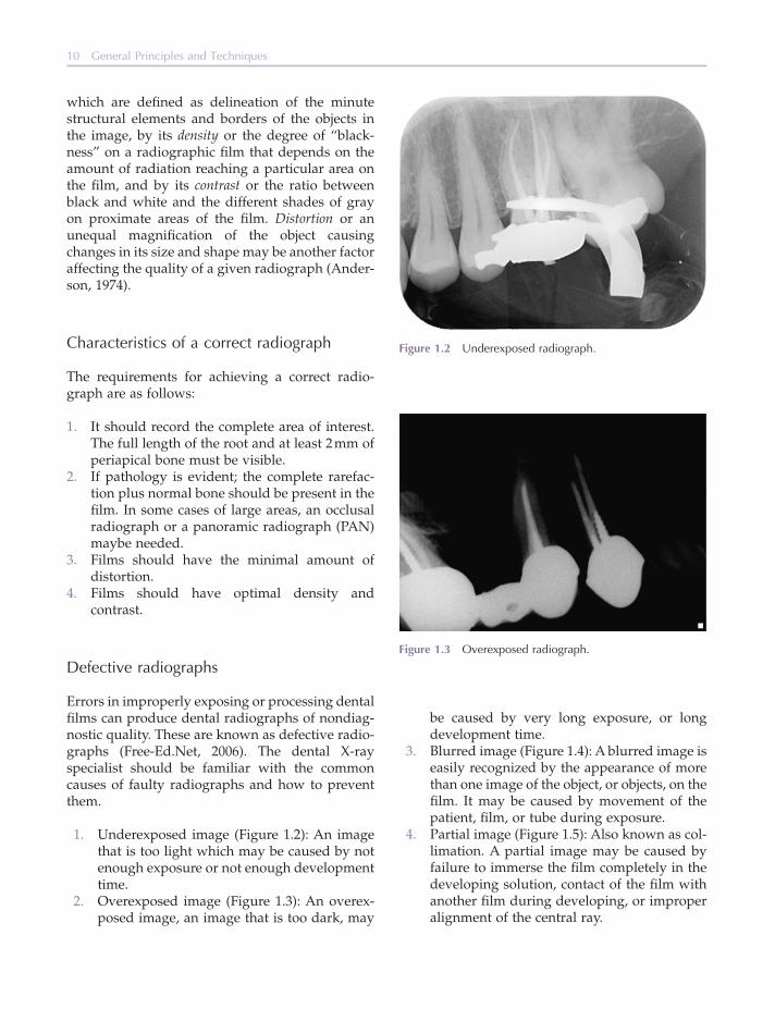
1. Underexposed image (Figure 1.2 ): An image that is too light which may be caused by not enough exposure or not enough development time.
2. Overexposed image (Figure 1.3 ): An overex-posed image, an image that is too dark, may
Figure 1.2 Underexposed radiograph.
Figure 1.3 Overexposed radiograph.
be caused by very long exposure, or long development time.
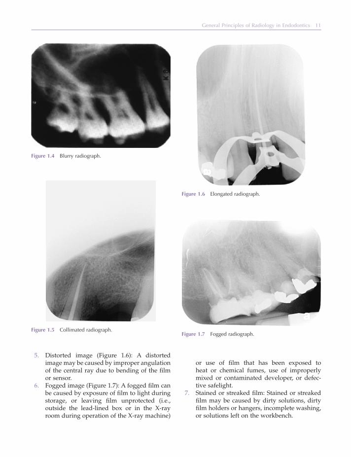
3. Blurred image (Figure 1.4 ): A blurred image is easily recognized by the appearance of more than one image of the object, or objects, on the fi lm. It may be caused by movement of the patient, fi lm, or tube during exposure.
4. Partial image (Figure 1.5 ): Also known as col-limation. A partial image may be caused by failure to immerse the fi lm completely in the developing solution, contact of the fi lm with another fi lm during developing, or improper alignment of the central ray.
General Principles of Radiology in Endodontics 11
Figure 1.4 Blurry radiograph.
Figure 1.5 Collimated radiograph.
5. Distorted image (Figure 1.6 ): A distorted image may be caused by improper angulation of the central ray due to bending of the fi lm or sensor.
6. Fogged image (Figure 1.7 ): A fogged fi lm can be caused by exposure of fi lm to light during storage, or leaving fi lm unprotected (i.e., outside the lead - lined box or in the X - ray room during operation of the X - ray machine)
Figure 1.6 Elongated radiograph.
Figure 1.7 Fogged radiograph.
or use of fi lm that has been exposed to heat or chemical fumes, use of improperly mixed or contaminated developer, or defec-tive safelight.
7. Stained or streaked fi lm: Stained or streaked fi lm may be caused by dirty solutions, dirty fi lm holders or hangers, incomplete washing, or solutions left on the workbench.

12 General Principles and Techniques
This happens when the fi lm is placed in backwards.
10. No image: No image may result if no current was passing through the tube at the time of exposure or if the fi lm was placed in the fi xing solution before it was placed in the develop-ing solution.
Control and c haracteristics of the X - r ay m achine
The X - ray beam emitted by the generating tube can be controlled and modifi ed by the operator. The milliamperage or the amount of electric charge fl owing past a circuit point at a specifi c time may affect the time required to generate a radiograph. High milliamperage is preferable in order to reduce the exposure time and limit radiation expo-sure; kilovoltage or the electrical potential differ-ence between the anode and cathode of an X - ray tube is set for dental radiographs in the range between 65 and 90 kVp. Radiographs generated with high kilovoltage will show increased density and reveal more details and information. Exposure time is the parameter most frequently controlled by the operator. It is equivalent to the amount of light allowed to fall on the photographic fi lm or sensor during the process of taking a photograph. Longer exposure time provides denser and darker radiographs. The spread of the X - ray beam is con-trolled by the collimator which consists of a barrier containing an aperture in the middle. It narrows the X - ray beam and minimizes the formation of secondary diffuse radiation. The collimator thus reduces exposure to excessive ionizing radiation and improves fi lm quality. A fi lter made as an alu-minum barrier is interposed in the path of the beam to eliminate X - rays with low penetrating power and low diagnostic benefi t. The distance between target and object is yet another parameter that controls the intensity of the X - ray beam (Anderson, 1974 ).
Radiographic p rocessing
One of the processing methods in dental radiogra-phy is the automatic processor. Most dental facili-ties use this processing method. With automatic
8. Scratched fi lm: When a fi lm is scratched by fi lm holders or hangers during the develop-ment process or when the digital PSP sensor needs to be replaced (Figure 1.8 ).
9. Lead - foil image (Figure 1.9 ): A lead - foil image occurs when the embossing pattern from the lead - foil backing appears on the radiograph. The embossing pattern consists of raised diamonds across both ends of the fi lm.
Figure 1.8 Scratched image.
Figure 1.9 Lead foil image.

General Principles of Radiology in Endodontics 13
the fi rst tooth on the left and then around the next tooth and the next, until the full mouth is scanned. Attention is then turned to the next structure, root form, tooth crowns, and so on. Much of radio-graphic interpretation is based on differentiation of normal versus abnormal conditions. Radio-graphical interpretation requires a comprehensive knowledge and familiarity of normal radiographic anatomy and of the oral cavity. Accurate inter-pretation requires the integration of clinical data, and information provided by the patient with the radiographic data is mandatory.
New h orizons in e ndodontic i maging
Alternative imaging techniques have been intro-duced over the years to overcome the existing limi-tations of intraoral radiographs (Abrahams, 2001 ; Cohenca et al., 2007 ; Nair and Nair, 2007 ; Patel et al., 2007, 2009 ).
Computed t omography ( CT )
Computerized axial tomography was fi rst intro-duced by Hannsfi eld during the l970s. CT is an X - ray imaging technique that produces 3D images of an object by using a series of 2D sets of image data and mathematically reconstructing the part under observation in a series of cross sections or planes: axial, coronal, and sagittal (Hannsfi eld,
processors, exposed fi lms are immediately loaded to the processors by unwrapping fi lms in the dark room. These processors are equipped with rollers and compartments fi lled with chemical solutions through which the fi lm advances. At the end of the processing cycle, the fi lm releases.
Another processing method in dental radiogra-phy is the manual process. This is done by using the standard time temperature method and a small container consisting of various solutions. The fi lm has to pass through different solutions including developing, rising, fi xing, washing, and drying in a temperature - controlled environment. These steps will give better dental radiographic image.
Viewing c onditions for r adiographs
Accurate diagnosis from radiographs depends upon optimal viewing conditions.
A magnifi er - viewer and adequate light are of the utmost importance (Brynolf, 1971 ). Sensitivity and specifi city has been shown to be reduced with inappropriate illumination (Patel et al., 2000 ). To maximize visual acuity, it is important that the retinal cones of the human eye receive an incident luminance of 100 candela per meter (cdmJ) (CEC, 1990 ). In diagnostic radiology, viewing boxes with low brightness will reduce the light reaching the eye, limiting visual acuity, and thus reducing the ability to carry out adequate assessment of radio-graphs. A good viewing box should also demon-strate consistent spatial illumination; otherwise, areas of the image will transmit less light than adja-cent areas even when optical densities in the two areas are the same. Also, ambient lighting should be minimized (see Table 1.2 ) (Abildgaard and Not-thellen, 1992 ).
Radiographic i nterpretation
Finally, the clinical information that can be derived from a radiograph depends on interpreting what is seen on the fi lm. Such interpretation should be per-formed systematically. An organized method for evaluation and interpretation of all types of radio-graphs should be applied on a series Wuehrmann (1970) . One structure should be reviewed at a time. For example, the lamina dura is followed around
Table 1.2 Published guidelines on radiological image viewing conditions.
Source of guidelines
Brightness of viewing box (cd m − 2 )
Uniformity of viewing box (%)
Ambient lighting (lux)
WHO (WHO, 1982 )
1500 – 3000 ≤ 15 ≤ 100
CEC (CEC, 1997 )
≥ 1700 ≤ 30 ≤ 5
WHO, World Health Organization; CEC, Commission of European Communities.
14 General Principles and Techniques
CBCT is usually served by unique software in which the images are displayed simultaneously in the three planes: axial, saggital, and coronal. Moving the cursor on one image simultaneously enables reconstruction in all three planes, allowing for dynamic evaluation of the area involved
CBCT is increasingly used in endodontics, allow-ing for the earlier detection of periapical disease as compared to conventional radiographs and in assessing the true size, extent, nature, and position of periapical and other resorptive lesions. Diagnos-ing root fractures and evaluation of root canal anatomy are also greatly enhanced by CBCT (Bartling et al., 2007 ; Estrela et al., 2008 ; Huumonen et al., 2006 ; Mora et al., 2007 ; Patel and Dawood, 2007 ; Rigolone et al., 2003 ; Velvart et al., 2001 ). It is extremely useful when planning apical microsurgery.
This new technology is still far from being perfect. At present, the spatial resolution of CBCT images is at the range of 2 line - pairs per millimeter, compared to that of conventional radiography which is in order of 15 – 20 line - pairs per millimeter (Patel, 2009 ).
Scattering caused by high - density neighboring structures such as enamel, gutta - percha, metal posts, and restorations is another unsolved problem with CBCT images, together with the need to per-fectly stabilize the patient for as long as 15 – 20 seconds (Estrela et al., 2008 ; Minami et al., 1996 ).
Magnetic r esonance i maging ( MRI )
MRI combines the use of a magnetic fi eld and radio waves. During an MRI exam, a magnetic fi eld is created. Different atoms in the body absorb radio waves at different frequencies under the infl uence of the magnetic fi eld. The absorption is measured and reconstructed by the software into images of the area examined (Haring and Lind, 1996 ). MRI is a completely noninvasive technique, since it uses radio waves and is not affected by metallic restora-tions (Abildgaard and Notthellen, 1992 ; Hashi-moto et al., 2003 ). MRI was used in dentistry to investigate the tissues of the temporomandibular joint and salivary glands (Goto et al., 2007 ). It may also help to determine the nature of the tissue in periapical lesions when planning surgical inter-
1973 ). CT is exceptional in that it provides imaging of a combination of soft tissues, bone, and blood vessels, and the technique became widely used for the diagnosis of pathologic conditions in max-illary and mandibular bones (Cotti and Campisi, 2004 ). CT provides valuable information regarding anatomy of the roots and their relation to adjacent anatomical structures such as the maxillary sinus or the inferior alveolar nerve. Information about the thickness of the cortical plates in a given area and their relation to the root apices is of particular interest when endodontic surgery is concerned (Nair and Nair, 2007 ).
CT also has several drawbacks. On the one hand, it requires high radiation doses and on the other hand, it has a limited low resolution as far as end-odontic diagnostic needs are concerned. Scatter from metallic objects presents yet another techno-logical drawback. The high cost of the CT machines which is refl ected in the cost of the scans and their limited availability are factors that limit the use of CT in endodontics (Patel, 2009 ; Patel et al., 2007 ).
Cone b eam c omputed t omography ( CBCT )
The CT is being greatly replaced in endodontics by CBCT (Figure 1.10 ) (Hashimoto et al., 2003, 2006, 2007 ). This technology was developed during the 1990s to produce 3D scans of the maxillofacial frame at a considerably lower radiation dose than the CT (Arai et al., 1999 ; Mozzo et al., 1999 ). The reduced radiation dose is a result of the rapid scan time, pulsed X - ray beam, and special image recep-tor sensors. CBCT differs from CT imaging in that the whole volume data are acquired by a single round of the scanner, rotating around the patient ’ s head 180 – 360 degrees, depending on the CBCT properties. One rotation results in up to 570 projec-tions or exposures. The X - ray beam is cone - shaped (hence the name of the technology) and captures a cylindrical or spherical volume of data called fi eld of view (Patel, 2009 ; Patel et al., 2007 ). Voxel size used in CBCT ranges between 0.08 and 0.4 mm 3 . The radiation dose may be further reduced by decreasing the size of the fi eld of view, increasing the voxel size, and/or reducing the number of pro-jection images during the rotation of the X - ray beam around the patient.

General Principles of Radiology in Endodontics 15
References
The Bible. King James version . Genesis . Chapter 1:3 – 4. CEC . ( 1990 ) Quality criteria for diagnostic radiographic
images . Working document (2nd ed.), XII/173/90: CEC, Brussels, Belgium.
Abildgaard , A. and Notthellen , J.A. ( 1992 ) Increased con-trast when viewing radiographic images . Radiology , 185 , 475 – 478 .
Abrahams , J.J. ( 2001 ) Dental CT imaging: a look at the jaw . Radiology , 219 , 334 – 345 .
Anderson , P.C. ( 1974 ) Dental Radiology . Delmar Publish-ers , Albany, NY .
Arai , Y. , Tammisalo , E. , Iwai , K. , Hashimoto , K. , and Shinoda , K. ( 1999 ) Development of a compact com-puted tomographic apparatus for dental use . Dento-maxillofac Radiol , 28 , 245 – 248 .
Bartling , S.H. , Majdani , O. , Gupta , R. et al. ( 2007 ) Large scan fi eld, high spatial resolution fl at - panel detector based volumetric CT of the whole human skull base and for maxillofacial imaging . Dentomaxillofac Radiol , 36 , 317 – 327 .
Bender , I.B. and Seltzer , S. ( 1961 ) Roentgenographic and direct observation of experimental lesions in bone . J Am Dent Assoc , 87 , 708 – 716 .
Brynolf , I. ( 1971 ) Improved viewing facilities for better roentgenodiagnosis . Oral Surg Oral Med Oral Pathol , 32 , 808 – 811 .
vention (Cotti and Campisi, 2004 ; Goto et al., 2007 ; Minami et al., 1996 ). The high cost of the unit scans, the limited availability, and the poor resolution of the scans limit the use of this technology in endodontics.
Ultrasound
Ultrasound is an imaging technology based on the refl ection of ultrasound waves called “ echos, ” gen-erated by a synthetic crystal. When the ultrasound beam comes across the interface between tissues possessing different acoustic properties, the echo is refl ected back to the crystal. The echoes are then transformed into light signals and then into moving images on a monitor. Ultrasound imaging is con-sidered to be a safe technique and is easy to perform. Its use in endodontics may allow detec-tion of periapical lesions and in determining whether vacuolization exists within the lesion, thus possibly allowing for differentiation between cysts and granulomas. Interpretation of the results of this diagnostic technology requires extensive experience.
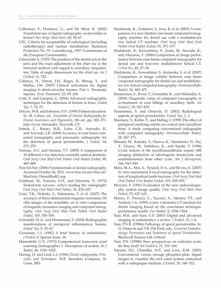
Figure 1.10 3D + cross sections of CBCT.
16 General Principles and Techniques
Hashimoto , K. , Yoshinori , Y. , Iwai , K. et al. (2003) A com-parison of a new limited cone beam computed tomog-raphy machine for dental use with a multidetector row helical CT machine . Oral Surg Oral Med Oral Pathol Oral Radiol Endod , 95 , 371 – 377 .
Hashimoto , K. , Kawashima , S. , Araki , M. , Sawada , K. , and Akiyama , Y. ( 2006 ) Comparison of image perfor-mance between cone - beam computed tomography for dental use and four - row multidetector helical CT . J Oral Sci , 48 , 27 – 34 .
Hashimoto , K. , Kawashima , S. , Kameoka , S. et al. ( 2007 ) Comparison of image validity between cone beam computed tomography for dental use and multidetec-tor row helical computed tomography . Dentomaxillofac Radiol , 36 , 465 – 471 .
Huumonen , S. , Kvist , T. , Grondahl , K. , and Molander , A. ( 2006 ) Diagnostic value of computed tomography in re - treatment of root fi llings in maxillary teeth . Int Endod J , 39 , 827 – 833 .
Huumonen , S. and Orstavik , D. ( 2002 ) Radiological aspects of apical periodontitis . Endod Top , 1 , 3 .
Marmary , Y. , Kotler , T. , and Heling , I. ( 1999 ) The effect of periapical rarefying osteitis on cortical and cancellous bone. A study comparing conventional radiographs with computed tomography . Dentomaxillofac Radiol , 28 , 267 – 271 .
Minami , M. , Kaneda , T. , Ozawa , K. , Yamamoto , H. , Itai , Y. , Ozawa , M. , Yoshikwa , K. , and Sasaki , Y. ( 1996 ) Cystic lesions of the maxillomandibular region: MR imaging distinction of odontogenic keratocysts and ameloblastomas from other cysts . Am J Roentgenol , 166 , 943 – 949 .
Mora , M.A. , Mol , A. , Tyndall , D.A. , and Rivera , E. ( 2007 ) In vitro assessment if local tomography for the detec-tion of longitudinal tooth fractures . Oral Surg Oral Med Oral Pathol Oral Radiol Endod , 103 , 825 – 829 .
Mouyen , F. ( 1991 ) Evaluation of the new radiovisiogra-phy system image quality . Oral Surg Oral Med Oral Pathol , 72 , 627 – 631 .
Mozzo , P. , Procacci , C. , Tacconi , A. , Martini , P.T. , and Andreis , I.A. ( 1999 ) A new volumetric CT machine for dental imaging based on the cone - beam technique: preliminary results . Eur Radiol , 8 , 1558 – 1564 .
Nair , M.K. and Nair , U.P. ( 2007 ) Digital and advanced imaging in endodontics: a review . J Endod , 33 , 1 – 6 .
Nair , P.N.R. ( 1998a ) Pathology of apical periodontitis . In: D. Orstavik and T.R. Pitt Ford , eds., Essential Endodon-tology: Prevention and Treatment of Apical Periodontitis . Blackwell Science Ltd , Oxford .
Nair , P.N. ( 1998b ) New perspectives on radicular cysts: do they heal? Int Endod J , 31 , 155 – 160 .
Naoum , H.J. , Chandler , N.P. , and Love , R.M. ( 2003 ) Conventional versus storage phosphor - plate digital images to visualize the root canal system contrasted with a radiopaque medium . J Endod , 29 , 349 – 352 .
Calberson , F. , Hommez , G. , and De Moor , R. ( 2005 ) Fraudulent use of digital radiographs: secret reality or fi ction? Rev Belge Med Dent , 60 , 58 – 67 .
CEC . Criteria for acceptability of radiological (including radiotherapy) and nuclear installations . Radiation Protection No. 91. Luxembourg, 1997 . Commission of the European Communities.
Cieszynski A. ( 1925 ) The position of the dental axis in the jaws and the exact adjustment of the chief ray in the intraoral method with regard to maxillary irregulari-ties: Table of angle dimensions for the chief ray . Int J Orthod , 11 , 742 .
Cohenca , N. , Simon , J.H. , Roges , R. , Morag , Y. , and Malfaz , J.M. ( 2007 ) Clinical indications for digital imaging in dento - alveolar trauma: Part 1. Traumatic injuries . Dent Traumatol , 23 , 95 – 104 .
Cotti , E. and Campisi , G. ( 2004 ) Advanced radiographic techniques for the detection of lesions in bone . Endod Top , 7 , 52 – 72 .
DeLyre , W.R. and Johnson , O.N. ( 1995 ) Patient education . In: M. Cohen , ed., Essentials of Dental Radiography for Dental Assistance and Hygienists , 5th ed ., pp. 365 – 371 . Julie Levin Alexander , Norwalk, CT .
Estrela , C. , Bueno , M.R. , Leles , C.R. , Azevedo , B. , and Azevedo , J.R. ( 2008 ) Accuracy of cone beam com-puted tomography and panoramic radiography for the detection of apical periodontitis . J Endod , 34 , 273 – 279 .
Farman , A.G. and Farman , T.T. ( 2005 ) A comparison of 18 different x - ray detectors currently used in dentistry . Oral Surg Oral Med Oral Pathol Oral Radiol Endod , 99 , 485 – 489 .
Free - Ed.Net . ( 2006 ) Fundamentals of dental radiography . Accessed October 26, 2011. www.free - ed.net/free - ed/MedArts/DentalRad01.asp
Goldman , M. , Pearson , A.H. , and Darzenta , N. ( 1972 ) Endodontic success — who ’ s reading the radiograph? Oral Surg Oral Med Oral Pathol , 33 , 432 – 437 .
Goto , T.K. , Nishida , S. , Nakamura , Y. et al. ( 2007 ) The accuracy of three - dimensional magnetic resonance 3D vibe images of the mandible: an in vitro comparison of magnetic resonance imaging and computed tomog-raphy . Oral Surg Oral Med Oral Pathol Oral Radiol Endod , 103 , 550 – 559 .
Gr ö ndahl , H. - G. and Huumonen , S. ( 2004 ) Radiographic manifestations of periapical infl ammatory lesions . Endod Top , 8 , 55 – 67 .
Grossman , L.I. ( 1982 ) A brief history of endodontics . J Endod , 8 , Special Issue, 36 .
Hannsfi eld , G.N. ( 1973 ) Computerized transverse axial scanning (tomography) 1. Description of system . Br J Radiol , 46 , 1016 – 1022 .
Haring , J.I. and Lind , L.J. ( 1996 ) Dental radiography: Prin-ciples and Techniques . W.B. Saunders Company , St. Louis, MO .

General Principles of Radiology in Endodontics 17
Richard , A.C. and Colquit , T.W.N. ( 1981 ) Reduction in dental x - ray exposures during the past 60 years . J Am Dent Assoc , 103 , 713 .
Rigolone , M. , Pasqualini , D. , Bianchi , L. , Berutti , E. , and Bianchi , S.D. ( 2003 ) Vestibular surgical access to the palatine root of the superior fi rst molar: “ low - dose cone - beam ” CT analysis of the pathway and its ana-tomic variations . J Endod , 29 , 773 – 775 .
Simon , J.H. ( 1980 ) Incidence of periapical cysts in relation to the root canal . J Endod , 6 , 845 – 848 .
Stashenko , P. , Teles , R. , and D ’ Souza , R. ( 1998 ) Perira-dicular infl ammatory responses and their modulation . Crit Rev Oral Bio Med , 9 , 498 – 521 .
Torabinejad , M. , Eby , W.C. , and Naidorf , I.J. ( 1985 ) Infl ammatory and immunological aspects of the pathogenesis of human periapical lesions . J Endod , 11 , 479 – 488 .
Velvart , P. , Hecker , H. , and Tillinger , G. ( 2001 ) Detection of the apical lesion and the mandibular canal in con-ventional radiography and computed tomography . Oral Surg Oral Med Oral Pathol Oral Radiol Endod , 92 , 682 – 688 .
Wenzel , A. and Grondahl , H.G. ( 1995 ) Direct digital radi-ography in the dental offi ce . Int Dent J , 45 , 27 – 34 .
WHO ( 1982 ) Quality Assurance in Diagnostic Radiology . World Health Organisation , Geneva, Switzerland .
Wuehrmann , A.H. ( 1970 ) Radiation hygiene and its prac-tice in dentistry as related to fi lm viewing procedures and radiographic interpretation. Council on Dental Materials and Devices . JADA , 80 , 346 – 356 .
NCRP Report . National Council on Radiation Protection and Measurements, Bethesda, MD Dental X - Ray Pro-tection , No. 35 , 1970 .
NCRP Report . Quality Assurance for Diagnostic Imaging Equipment , No. 99 , 1988 .
NCRP Report . Radiation Protection for Medical and Allied Health Personnel , No. 105 , 1989 .
NCRP Report . Implementation of the Principle of as Low as Reasonably Achievable (ALARA) for Medical and Dental Personnel , No. 107 , 1990 .
Patel , N. , Rushton , V.E. , Macfarlane , T.V. , and Horner , K. ( 2000 ) The infl uence of viewing conditions on radio-logical diagnosis of periapical infl ammation . Br Dent J , 189 , 40 – 42 .
Patel , S. ( 2009 ) New dimensions in endodontic imaging: part 2. Cone beam computed tomography . Int Endod J , 42 , 463 – 475 .
Patel , S. and Dawood , A. ( 2007 ) The use of cone beam computed tomography in the management of exter-nal cervical resorption lesions . Int Endod J , 40 , 730 – 737 .
Patel , S. , Dawood , A. , Whaites , E. , and Pitt Ford , T. ( 2007 ) The potential applications of cone beam computed tomography in the management of endodontic pro-blems . Int Endod J , 40 , 818 – 830 .
Patel , S. , Mannocci , F. , Wilson , R. , Dawood , A. , and Pitt Ford , T. ( 2009 ) Detection of periapical bone defects in human jaws using cone beam computed tomog-raphy and intraoral radiography . Int Endod J , 42 , 507 – 515 .