general principles of operating with can-bus of a vehicle · general principles of operating with...
TRANSCRIPT
2016
General principles of operating with CAN-bus
of a vehicle

General principles of operating with CAN-bus of a vehicle
RSA “GALILEOSKY”, LLC Page 1
Contents Manual Objectives......................................................................................................................................... 2
Necessary tools, devices, materials .............................................................................................................. 3
General information ...................................................................................................................................... 5
Topology of CAN-bus ..................................................................................................................................... 6
Transmission of messages in CAN-bus .......................................................................................................... 7
Connection of the terminal to CAN-bus ...................................................................................................... 10
Settings of terminal’s operating .................................................................................................................. 15
Modes of operation..................................................................................................................................... 16
Monitoring software configuring ................................................................................................................ 21

General principles of operating with CAN-bus of a vehicle
RSA “GALILEOSKY”, LLC Page 2
Manual Objectives
1. Receive general information on CAN interface.
2. Learn principles of operating of CAN-bus in vehicles.
3. Get a general description of protocols operating over CAN interface.
4. Learn the ways of connection of the terminal to CAN-bus of a vehicle.
General principles of operating with CAN-bus of a vehicle
RSA “GALILEOSKY”, LLC Page 3
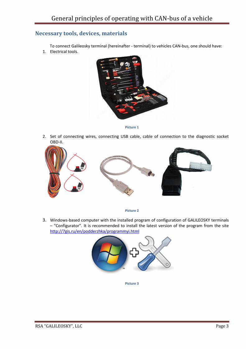
Necessary tools, devices, materials To connect Galileosky terminal (hereinafter - terminal) to vehicles CAN-bus, one should have:
1. Electrical tools.
Picture 1
2. Set of connecting wires, connecting USB cable, cable of connection to the diagnostic socket OBD-II.
Picture 2
3. Windows-based computer with the installed program of configuration of GALILEOSKY terminals – "Configurator". It is recommended to install the latest version of the program from the site http://7gis.ru/en/podderzhka/programmyi.html
Picture 3
General principles of operating with CAN-bus of a vehicle
RSA “GALILEOSKY”, LLC Page 4
4. A measuring device – a multimeter.
Picture 4
5. An oscillograph.
Picture 5
6. Galileosky terminal (hereinafter – terminal) with CAN support. You can download a manual for
connection of the terminal from our site http://7gis.ru/en/podderzhka/dokumentacziya.html
Picture 6

General principles of operating with CAN-bus of a vehicle
RSA “GALILEOSKY”, LLC Page 5
General information
CAN-bus was developed by BOSH and INTEL company in 1980s as a multitask system transmitting messages with the speed of up to 1 Mb/s. First, CAN was intended to control a transmission in real time, anti-skidding system and replacing of radial wiring of a vehicle. Later, the standard was used in all industrial spheres: space industry, military industry, automobile construction, aviation, machine tool industry, modern security systems.
The network consists of units with their own clock generators and a stretch cooper cord that connects these units. Unlike traditional networks of data transmission, CAN-bus does not transmit large data packets from point A to point B. CAN system contains many short messages (temperature, engine speed, etc.) that are transmitted to the whole network by any units with no exception. Any unit of the CAN network decides whether this message relates to it. To solve this task CAN has a hardware implementation of message filtering.
CAN controllers are connected by the differential bus, which has two lines - CAN_H (Сan-High) and CAN_L (Can-Low), through which signals are transmitted (pic. 7).
Picture 7. Standard scheme of the CAN bus

General principles of operating with CAN-bus of a vehicle
RSA “GALILEOSKY”, LLC Page 6
Topology of CAN-bus
Modern cars may contain several types of CAN-buses:
CAN-bus of a power pack (high speed CAN) allows to transmit information with speed of up to 500 Kbit/s. It serves as a connection between control units on the level of engine and transmission. It may be in a dominant mode when the ignition is on:
CAN-bus of a power pack
Engine electronic control unit
Transmission electronic control unit
Airbags control unit
ABS electronic control unit
EAS control unit
High pressure fuel pump control unit
Central setting block
Electronic ignition switch
Steering angle sensor
CAN-bus of “Comfort system” (low speed CAN) allows to transmit information with speed of up to 100 Kbit/s. It serves as a connection between control units included into “Comfort” system and others. It may be in a dominant mode when the ignition is off:
CAN-bus of “Comfort” system
Multi Information Display (MID)
Doors Electronic Control Unit (ECU)
Parking System Electronic Control Unit
“Comfort” system control unit
Windscreen wiper control unit
Tire pressure control
CAN-bus of command and data system (low speed CAN) allows to transmit information with speed of up to 100 Kbit/s. It serves as a connection between different service systems. It may be in a dominant mode when the ignition is off:
CAN-bus of command and data system
Multi Information Display (MID)
Audio system
Data system
Navigation system
Some cars contain a common double-wire cable for CAN-buses of “Comfort” and command and data systems, but others have contours of the bus performed separately.

General principles of operating with CAN-bus of a vehicle
RSA “GALILEOSKY”, LLC Page 7
Transmission of messages in CAN-bus There are two different modes of CAN-bus: dominant (presence of messages in a bus, logical 0) and recessive (no messages in a bus, logical 1). Electrical signals coming from CAN-bus of a power pack (pic. 8) are different from the signals coming from CAN-bus of “Comfort” and command and data systems (pic.9):
Picture 8. Form of a signal coming via wires of a power pack CAN-bus
Thus, once CAN-bus of a power pack switches into a dominant mode, voltage of High wire steps up to 3,5V (2,5V+1V=3,5V), voltage of Low wire steps down to 1,5V (2,5V-1V=1,5V). When CAN-bus is in a recessive mode, voltage difference of wires is zero, when it is in a dominant mode, voltage difference of wires is not less than 2V (pic. 8).
Picture 9. Form of a signal coming via wires of “Comfort” and command and data systems CAN-bus
When CAN-bus of “Comfort” system is in a recessive mode, voltage of High wire is zero, it steps up to 3,6V in a dominant mode. When CAN-bus is in a recessive mode, voltage of Low wire is 5V; it steps down to 1,4V in a dominant mode. That is why, after voltage difference development in a differential amplifier, a recessive signal level is 5V, and dominant level is 2,2V. Thus, voltage difference in recessive and dominant modes of the bus is equal to or more than 7,2V (pic. 9).
A function of messages transmission between different types of buses is carried out by internetwork interface (pic.10):

General principles of operating with CAN-bus of a vehicle
RSA “GALILEOSKY”, LLC Page 8
Picture 10. CAN-bus of a power pack, CAN-bus of «Comfort” system and CAN-bus of command and data system
For example, some cars (Audi, Volkswagen) have a dashboard serving as a gateway server (internetwork interface) between a high speed and a low speed bus. As for Mercedes cars, EZS (ignition switch) serves as a gateway server.
Data in CAN are transmitted by short messages of a standard format. There are four types of
messages in CAN: – Data Frame – Remote Frame – Error Frame – Overload Frame Data Frame is the most frequently used type of a message. It contains the following parts:
arbitration field defines a priority of a message, in case two or more units try to transmit data to
the network simultaneously. Arbitration field consists of:
for standard CAN-2.0A, 11-bit identifier + 1 bit RTR (retransmit)
for standard CAN-2.0B, 29-bit identifier + 1 bit RTR (retransmit)
data field contains from 0 to 8 bytes of data;
CRC field contains 15-bit checksum of a message that is used for detection of errors;
acknowledgement slot (1 bit). Each CAN-controller that received a message correctly sends a
confirmation bit to the network. A unit that sent a message listens to the bit, in case there is no
confirmation, it retransmits the message. If an acknowledgement slot is received, it means at
least one of the units in the network received the message correctly.

General principles of operating with CAN-bus of a vehicle
RSA “GALILEOSKY”, LLC Page 9
Picture 11. Structure of informational message in CAN 2.0A
Remote Frame is a Data Frame with no data field, but with RTR bit (1 – a recessive bit). The main purpose of Remote message is initiation by one of the network units of data transmission to the network by another unit. Such scheme allows to decrease a total network traffic.
Error Frame is a message that breaks the format of CAN message. Transmission of such message leads to a registration of CAN-message error by all units, and they automatically transmit Error Frame to the network. As a result, a transmitting unit resends data to the network. Error Frame consists of Error Flag field that involves 6 bits of the same value and Error Delimiter, involving 8 recessive bits. Error Delimiter allows other network units to send Error Flag once Error frame is detected.
Overload Frame repeats the structure and logic of Error message operation. The difference is – it is used by an overloaded unit that cannot process a message, that is why, it requests a resending using Overload message.
CAN-bus standard is currently implemented in two versions: version CAN 2.0A has 11bit identifiers in messages (i.e. 2048 messages can be in the system) and CAN2.0B has 29bit identifiers (536 million messages). This standard describes the way messages (packets) should be transmitted from one network unit to another, but there is no information on the way of interpretation of data fields of these messages or usage of arbitrage (identifier) of the messages. For this, there are some high layer protocols implemented on CAN standard basis: CANopen, CCP/XCP, DeviceNet, MilCAN, NMEA 2000®, OSEK/VDX, SDS, EnergyBus, LIN bus, J1587, J1708, J2534 (J1939, J1979), RP1210A, RP1210, etc.
Further, terminal’s operation with J1939 and J1979 protocols will be considered.
General principles of operating with CAN-bus of a vehicle
RSA “GALILEOSKY”, LLC Page 10
Connection of the terminal to CAN-bus
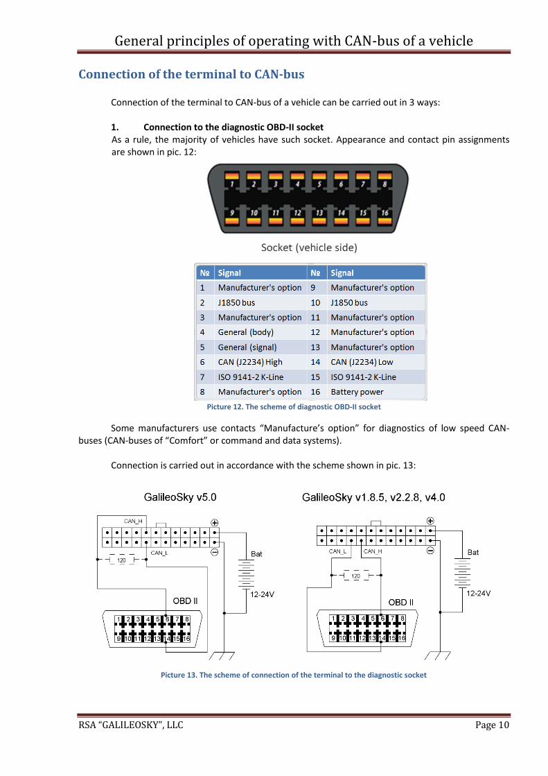
Connection of the terminal to CAN-bus of a vehicle can be carried out in 3 ways: 1. Connection to the diagnostic OBD-II socket As a rule, the majority of vehicles have such socket. Appearance and contact pin assignments are shown in pic. 12:
Picture 12. The scheme of diagnostic OBD-II socket
Some manufacturers use contacts “Manufacture’s option” for diagnostics of low speed CAN-buses (CAN-buses of “Comfort” or command and data systems).
Connection is carried out in accordance with the scheme shown in pic. 13:
Picture 13. The scheme of connection of the terminal to the diagnostic socket

General principles of operating with CAN-bus of a vehicle
RSA “GALILEOSKY”, LLC Page 11
ATTENTION! There is an option when a diagnostic socket OBD-II is connected not to a CAN-bus, but to one of the units, for example, a set of devices (pic. 7). Consequently, the terminal cannot listen to a CAN-bus and get identifiers. In this case, use command ActiveCAN 1.
Command format ActiveCAN OnOff
Parameters OnOff parameters– operating mode: 0 – passive mode: packets receiving confirmations are not sent to CAN bus. It is a safe mode of operation. It does not interfere with the on-board equipment; 1 – active mode: packets receiving confirmations are sent to CAN bus.
Explanation Control of packets confirmation sending to CAN bus. Confirmation sending may be necessary at connection to the troubleshooting socket, if the data cannot be read in a passive mode.
Example Request: ActiveCAN 1 Reply: ACTIVECAN:1;
Use this command only in the above situation and with care, because in this mode, the terminal emulates the operation of the units of the car!
2. Direct connection to CAN bus Direct connection to CAN-bus is carried out in case there is no diagnostic socket or the CAN lines
are not brought to it, and if it does not contradict conditions of the warranty service. Connection is carried out by dismantling a part of a dashboard, finding a twisted CAN pair (it is located in different places depending on a car model) and connecting to it in accordance with the scheme (pic. 14), for example, as shown in picture 15:
Picture 14. The scheme of direct connection of the terminal to CAN-bus

General principles of operating with CAN-bus of a vehicle
RSA “GALILEOSKY”, LLC Page 12
Picture 15. The example of direct connection of the terminal to CAN-bus in a harness of a steering tube of VW Caravelle 2014
production year
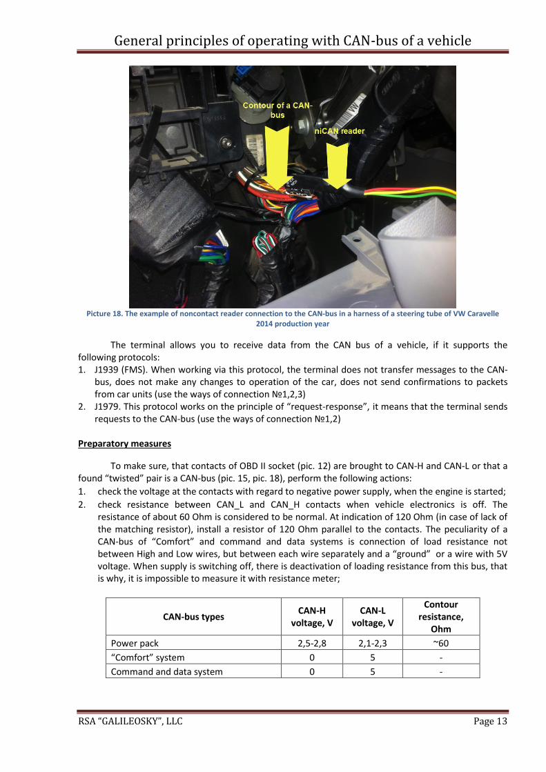
3. Connection to CAN-bus with noncontact readers Connection to CAN-bus with the help of noncontact readers, for example, niCAN or CAN
crocodile (pic.16 and pic.17). This option is the safest, as such readers allow to read CAN-bus messages without interfering into wire intact insulation (pic. 18). Such connection allows just to listen to the messages, but requests sending is possible only by direct connection (p.1 and p.2).
Picture 16. Noncontact reader of a CAN-bus niCAN
Picture 17. Noncontact reader of a CAN-bus CAN crocodile
General principles of operating with CAN-bus of a vehicle
RSA “GALILEOSKY”, LLC Page 13
Picture 18. The example of noncontact reader connection to the CAN-bus in a harness of a steering tube of VW Caravelle
2014 production year
The terminal allows you to receive data from the CAN bus of a vehicle, if it supports the following protocols: 1. J1939 (FMS). When working via this protocol, the terminal does not transfer messages to the CAN-
bus, does not make any changes to operation of the car, does not send confirmations to packets from car units (use the ways of connection №1,2,3)
2. J1979. This protocol works on the principle of “request-response”, it means that the terminal sends requests to the CAN-bus (use the ways of connection №1,2)
Preparatory measures
To make sure, that contacts of OBD II socket (pic. 12) are brought to CAN-H and CAN-L or that a found “twisted” pair is a CAN-bus (pic. 15, pic. 18), perform the following actions:
1. check the voltage at the contacts with regard to negative power supply, when the engine is started;
2. check resistance between CAN_L and CAN_H contacts when vehicle electronics is off. The resistance of about 60 Ohm is considered to be normal. At indication of 120 Ohm (in case of lack of the matching resistor), install a resistor of 120 Ohm parallel to the contacts. The peculiarity of a CAN-bus of “Comfort” and command and data systems is connection of load resistance not between High and Low wires, but between each wire separately and a “ground” or a wire with 5V voltage. When supply is switching off, there is deactivation of loading resistance from this bus, that is why, it is impossible to measure it with resistance meter;
CAN-bus types CAN-H
voltage, V CAN-L
voltage, V
Contour resistance,
Ohm
Power pack 2,5-2,8 2,1-2,3 ~60
“Comfort” system 0 5 -
Command and data system 0 5 -

General principles of operating with CAN-bus of a vehicle
RSA “GALILEOSKY”, LLC Page 14
3. connect 2 oscillograph probes to CAN-H and CAN-L contacts (either in a diagnostic socket or directly to the bus), GND-contacts of an oscillograph and CAN-bus should be common, also, check presence of messages, when the engine is on (signal in a bus of a power pack is shown in pic.19).
Picture 19. Messages in CAN-bus of a power pack (High (red) and Low (blue)) on the monitor of an oscilloscope

General principles of operating with CAN-bus of a vehicle
RSA “GALILEOSKY”, LLC Page 15
Settings of terminal’s operating
All configuration of the terminal can be produced in two ways:
1. Setting via Configurator. Run Configurator program, go to “Settings” tab -> “CAN” and run necessary settings (pic. 20)
Picture 20. Setting for receiving data from the CAN-bus in Configurator
2. Setting by CanRegime command. It is mostly used for remote configuration by SMS or
commands sent from monitoring software.
Command format CanRegime Mode,BaudRate,TimeOut, DoNotCleanAfterTimeOut
Parameters Mode – operating mode:
0 – CAN interface is off and is not used;
1 – standard FMS filter;
2 – user filter 29 bit;
3 – user filter 11 bit;
4 – OBD II 29 bit;
5 – OBD II 11 bit. BaudRate – bus rate. It must be the same as the vehicle bus rate. It can have the following values: from 10000 up to 500000. Typical valuations: 62500, 125000, 250000, 500000.
TimeOut – measured in msec. For CAN_SCANER mode it is response latency. If it is too small, not all bus messages will be received. The recommended time for CAN_SCANER is 2000 msec. For all the rest modes, it is time to receive at least one message; otherwise, the value will be set to zero. DoNotCleanAfterTimeOut – not to reset data in case of connection loss with CAN-bus
Explanation General CAN bus control.
Example Example: Enable scanner for a 250000 b/sec bus with the message latency equal to 2 sec. Request: CanRegime 1,250000,2000,0 Reply: CANREG: Mode=1,BaudRate=250000,TimeOut=2000; DoNotCleanAfterTimeOut=0;

General principles of operating with CAN-bus of a vehicle
RSA “GALILEOSKY”, LLC Page 16
Modes of operation
1. FMS mode A standard filter of J1939 protocol. In case a manufacturer of a vehicle (generally, it is about
producers of heavy-load equipment, agricultural equipment) supports FMS standard, the choice of this mode allows to read and decrypt the messages conforming to FMS standard automatically:
1.1. total fuel consumption – the amount of fuel the vehicle has used since it was made; 1.2. tank fuel level, measured in percent (0% - empty, 100% - full); 1.3. coolant temperature; 1.4. engine speed; 1.5. total mileage; 1.6. moto hours (messages can be transmitted to the monitoring server); 1.7. axle load (messages can be transmitted to the monitoring server).
ATTENTION! Many manufacturers support FMS protocol partially or do not support it at all. For operating in FMS mode:
go to tab “Settings” -> “CAN” and choose the filter type “FMS”;
select a necessary bus speed (pic.21);
click “Apply” button.
Picture 21. FMS mode setting in Configurator
The second option of setting: send CanRegime 2,250000,2000,0 command on “Commands” tab.
Make sure the terminal receives bus data and sends them to the “Device” tab in the
Configurator (pic. 22):
Picture 22. The results of analysis of data from CAN-bus via FMS standard
To send the received data to the monitoring server go to “Settings” tab -> “Protocol” of Configurator, configure the main packet to transmit CAN-bus data to the server (pic. 23) and click “Apply” button:

General principles of operating with CAN-bus of a vehicle
RSA “GALILEOSKY”, LLC Page 17
Picture 23. Selection of parameters to be sent to the monitoring server
2. Listen CAN mode The mode is intended to receive all CAN messages currently transferred in a bus. Speed from
10000 bit/s to 500000 bit/s (standard values: 62500, 12500, 250000, 500000) are supported. The 11-bit and 29-bit identifiers are supported.
For operating in this mode go to tab “Settings” -> “CAN” and select one of the parameters:
bus rate;
latency time (of a message);
filter type is not important in this case (pic. 24);
click “Listen CAN” button.
The second option of setting: send CanRegime 2,250000,2000,0 command on “Commands” tab.
In case of successful setting, received data will be displayed in the right panel.
Picture 24. Configuring scanning of CAN-bus in Configurator

General principles of operating with CAN-bus of a vehicle
RSA “GALILEOSKY”, LLC Page 18
The scanning mode is carried out in the following way:
2.1. «CAN. Start scan.» message is displayed; 2.2. CAN bus messages in identifiers ascending order with the established delay start being
displayed; 11- bit identifiers are displayed as: - ID=009 (8) 01 02 03 04 05 06 07 08, where
ID – 11-bit message identifier; (8) – the number of received bytes from the bus; 01 02 03 04 05 06 07 08 – an 8-byte message (the lower byte on the left, the high byte on the right);
29-bit identifiers are displayed in the following format: - ID=00000009 (8) 01 02 03 04 05 06 07 08, where
ID – 29-bit message identifier; (8) – the number of received bytes from the bus; 01 02 03 04 05 06 07 08 – an 8-byte message (the lower byte on the left, the high byte on the right);
2.3. after all the identifiers have been displayed you can see the «CAN. End scan.» message.
To decrypt messages received via this protocol, check the manual on our site www.7gis.ru “CAN-bus. Receiving data on fuel level from the CAN-bus”. After that, configure a user filter as described below.
3. User filter J1939 11bit identifiers, 29bit identifiers These modes enable to attach values received by listening to CAN-bus via J1939 protocol to tags
in Galileosky protocol. As a rule, these modes are used, if the data received on FMS standard are not enough or FMS
standard is not supported, but data on J1939 protocol are present at the bus. Configure attachment of received data to Galileosky protocol tags (pic. 25) in the following
order:
Picture 25. Setting a custom filter J1939 mode
3.1. listen to CAN-bus messages, having executed actions according to the description of p.2 "Listen
CAN mode" given above; 3.2. select the filter type “ J1939 custom filter, 29 (or 11)-bit identifiers”;

General principles of operating with CAN-bus of a vehicle
RSA “GALILEOSKY”, LLC Page 19
3.3. decrypt messages in accordance with the manual at http://7gis.ru/en/podderzhka/dokumentacziya.html “CAN-bus. Receiving data on fuel level from the CAN-bus”
3.4. in case it is impossible to decrypt data, ask your dealer or car manufacturer which data in the identifiers are responsible for work of this or that unit of the vehicle. These data can be transmitted in one, two or four bytes in identifiers;
3.5. establish compliance between data in identifiers and one-byte, two-byte and four-byte tags of Galileosky protocol, i.e. if in the message from all accepted data only one byte is necessary, it is more reasonable to compare a one-byte tag of Galileosky protocol. From the useful information received on this identifier, it is possible to choose that part of bytes, which have to be filled in tag contents by means of shift. Execute these operations as follows: 3.5.1. specify the identifier in the first column of the table; 3.5.2. choose the corresponding tag in the second one; 3.5.3. specify the shift using a mouse and the number of transmitted bytes in the third
column; 3.5.4. the number transmitted to the server will be displayed in the fourth column "Value".
3.6. click “Apply” button; 3.7. to send received data to the monitoring server go to “Settings” tab -> “Protocol” of
Configurator, configure the main packet to transmit the chosen tags to the server (pic. 26) and click “Apply” button;
Picture 26. Selection of parameters to be sent to the monitoring server
4. Test OBD-II mode (J1979 protocol)
This mode is used to define data transfer rate in the bus and identifiers type via J1979 protocol. The rate of 250000 bit/s and 500000 bit/s, 11-bit and 29-bit identifiers are supported. Operation with this mode of connection is carried out via a diagnostic socket OBD-II or directly to CAN-bus.
To enable this mode in the Configurator go to “Settings” tab -> “CAN” click “Test OBD II” button (pic. 27):
Picture 27. Selecting the operating mode by J1979 protocol
The terminal starts sending requests with a definite identifier at different bus rates. In case of
J1979 protocol support, the following parameters will be set automatically: “Bus rate” (250000 bit/s or 500000 bit/s) and “Filter type” (OBD II, 29-bit identifiers or OBD II, 11- bit identifiers).

General principles of operating with CAN-bus of a vehicle
RSA “GALILEOSKY”, LLC Page 20
Go to tab “Device” and make sure retrieved and decrypted messages, transmitted via J1979 protocol, are displayed (pic. 28):
4.1. tank fuel level, measured in percent. 0% - empty. 100% - full; 4.2. coolant temperature; 4.3. engine speed; 4.4. errors codes (messages can be displayed on tab ”Troubleshooting” or transmitted to the
monitoring server); 4.5. readings of a mass air flow sensor (messages are displayed on tab “Troubleshooting”); 4.6. status of engine failure sensor (messages are displayed on tab “Troubleshooting”); 4.7. OBD standard of the vehicle (messages are displayed on tab “Troubleshooting”).
Picture 28. The results of analysis of data from the CAN-bus via J1979 protocol
ATTENTION! Scanning in Test OBD II mode may cause problems in the operation of on-board equipment of the vehicle. RSA “Galileosky”, LLC disclaim all liability concerning failures caused by operation of this mode.
To send received data to the monitoring server go to “Settings” tab -> “Protocol” of Configurator, configure the main packet to transmit tags CAN_A1, CAN16BITR0-CAN16BITR4 to the server (pic. 29) and click “Apply” button;
Picture 29. Selection of parameters to be sent to the monitoring server

General principles of operating with CAN-bus of a vehicle
RSA “GALILEOSKY”, LLC Page 21
Monitoring software configuring Connection of the terminal to CAN-bus ends with checking the correctness of data transmission
to the monitoring server (pic.30):
Picture 30. Displaying the indications in the program of monitoring server
Connection of CAN-bus of the vehicle to the Galileosky terminal is completed; the terminal is
ready to operate.