general notes - florida department of transportation · general notes: channelizing devices ......
TRANSCRIPT

10/30/2017
9:3
6:4
3
AM
RE
VISIO
N DESCRIPTION:
REVISION
LAST
ofSTANDARD PLANS
FY 2018-19 SHEETINDEX
11/01/17 CONTROL THROUGH WORK ZONESGENERAL INFORMATION FOR TRAFFIC
102-600 1 12
SHEET CONTENTS
1
2
Definitions
Temporary Traffic Control Devices
Pedestrian and Bicyclist
Overhead Work
Railroads
Sight Distance
Above Ground Hazard
3
Clear Zone Widths For Work Zones
Superelevation
Length Of Lane Closures
Overweight/Oversize Vehicles
Lane Widths
High-Visibility Safety Apparel
Regulatory Speeds In Work Zones
4
Flagger Control
Survey Work Zones
Signs
5 Work Zone Sign Supports
6 Project Information Sign
7 Commonly Used Warning and Regulatory Signs In Work Zones
8
Manholes/Crosswalks/Joints
Truck Mounted Attenuators
Removing Pavement Markings
Signals
Portable Changeable (Variable) Message Signs (PCMS)
Advanced Warning Arrow Boards
9 Drop-Offs In Work Zones
10Business Entrance
Temporary Asphalt Separator
11
12 Pavement Markings
Channelizing Devices
Channelizing Devices Consistency
General Notes
GENERAL NOTES:
Channelizing Devices Notes
Temporary Barrier Notes
shall comply with Section 335.15, F.S.
3. Except for emergencies, any road closure on State Highway System
criteria for any changes and document the reason for the change.
channelizing devices. Comply with MUTCD or applicable Department
Flaggers, portable temporary signals, signs, pavement markings, and
and approved by the Engineer. Devices include, but are not limited to,
or number thereof as recommended by the Worksite Traffic Supervisor
applications of commonly encountered situations. Adjust device location
2. Indexes 102-601 through 102-670 are Department-specific typical
provided in the MUTCD.
jurisdiction may adopt requirements based on the minimum requirements
off the State Highway System, the local agency (City/County) having
volume nature of State Highways. For highways, roads and streets
System. Certain requirements in this Index are based on the high
and utility work on highways, roads and streets on the State Highway
control in work zones, for construction and maintenance operations
preparation of traffic control plans and for the execution of traffic
specific to the Federal and State guidelines and standards for the
plan and Department-approved procedures. This Index contains information
traffic control plan. All work shall be executed under the established
1. All projects and works on highways, roads and streets shall have a

10/30/2017
9:3
6:4
3
AM
RE
VISIO
N DESCRIPTION:
REVISION
LAST
ofSTANDARD PLANS
FY 2018-19 SHEETINDEX
11/01/17 CONTROL THROUGH WORK ZONESGENERAL INFORMATION FOR TRAFFIC
102-600 2 12
DEFINITIONS OVERHEAD WORK
TEMPORARY TRAFFIC CONTROL DEVICES
PEDESTRIAN AND BICYCLIST
SIGHT DISTANCE
RAILROADS
Regulatory Speed (In Work Zones)
Advisory Speed
Travel Way
Detour, Lane Shift, and Diversion
Aboveground Hazard
LANE CLOSURE)
OPTION 1 (OVERHEAD WORK USING A MODIFIED
TRAFFIC LANE)
OPTION 2 (OVERHEAD WORK ABOVE AN OPEN
TRAFFIC LANE)
OPTION 3 (OVERHEAD WORK ADJACENT TO AN OPEN
NO ENCROACHMENT BELOW THE OVERHEAD WORK AREA)
OPTION 4 (OVERHEAD WORK MAINTAINING TRAFFIC WITH
TRAFFIC LANE)
OPTION 5 (CONDUCTOR/CABLE PULLING ABOVE AN OPEN
similar features.
lengths, crash cushion requirements, marker spacings, superelevation and other
lengths, departure rates, flare rates, lengths of need, clear zone widths, taper
plans. This speed should be used as the minimum design speed to determine runout
regulatory speed limit signs. The work zone speed must be shown or noted in the
The maximum permitted travel speed posted for the work zone is indicated by the
The maximum recommended travel speed through a curve or a hazardous area.
within the limits of the right of way.
traffic onto a temporary roadway, usually adjacent to the permanent roadway and
different section of the permanent pavement. A diversion is the redirection of
temporary traffic control zone. A lane shift is the redirection of traffic onto a
A detour is the redirection of traffic onto another roadway to bypass the
options is used:
Work is only allowed over a traffic lane when one of the following
through traffic.
separate speed change, turning, passing and climbing maneuvers from
Auxiliary Lane: The designated widths of roadway pavement marked to b.
other traffic lanes.
through traffic and to separate it from opposing traffic or traffic occupying
Travel Lane: The designated widths of roadway pavement marked to carry a.
movement of vehicular traffic.
any other permanent or temporary surface intended for use as a lane for the
through work zones, travel way may include the temporary use of shoulders and
The portion of the roadway for the movement of vehicles. For traffic control
flagmen and/or a traffic control officer.
Volume or complexity of the roadway may dictate additional devices, signs, g.
closing the lane using a minimum 100 foot taper.
Traffic control devices are placed in advance of the vehicle/equipment f.
lane.
Aerial lift equipment is placed directly below the work area to close the e.
oscillating, or strobe lights operating.
Aerial lift equipment in the work area has high-intensity, rotating, flashing, d.
Speed limit is 45 mph or less.c.
Work operations are 60 minutes or less.b.
limited to signals, signs, lighting and utilities.
Work operation is located in a signalized intersection and a.
conditions are met:
Overhead work using a modified lane closure is allowed if all of the following
greater clearance. The greater clearance required prevails as the rule.
Other Governmental Agencies, Rail facilities, or Codes may require a h.
other objects from falling into open lanes of traffic.
Adequate precautions are taken to prevent parts, tools, equipment and g.
signs, flagmen and/or a traffic control officer.
Volume or complexity of the roadway may dictate additional devices, f.
flashing, oscillating, or strobe lights operating.
Aerial lift equipment in the work area has high-intensity, rotating, e.
18 feet high.
within an area bounded by 2 feet outside the edge of travel way and
No encroachment by any part of the work activities and equipment d.
Speed limit is 45 mph or less.c.
Work operations are 60 minutes or less.b.
their appurtenances.
Work operation is located on a utility pole, light pole, signal pole, or a.
conditions are met:
Overhead work above a open traffic lane is allowed if all of the following
locations, signal timing, etc.
traffic volumes, distance from the tracks to the intersections, lane closure or taper
controls to reduce queuing on the tracks. The evaluation should include as a minimum:
Railroad crossings affected by a construction project should be evaluated for traffic
Construction equipment and materials shall not restrict intersection sight distance.
the road user to perceive potential conflicts and to traverse the intersection safely.
Intersections: Traffic control devices at intersections must provide sight distances for
curves.
advance of the view obstruction. The beginning of tapers should not be hidden behind
problem (e.g., a sharp vertical or horizontal curve), the taper should begin well in
Tapers: Transition tapers should be obvious to drivers. If restricted sight distance is a
appropriate signs.
Advanced notification of sidewalk closures and marked detours shall be provided by
temporary traffic control zone pedestrian walkway.
Only approved pedestrian longitudinal channelizing devices may be used to delineate a
zone, accommodation must be maintained and provision for the disabled must be provided.
When an existing pedestrian way or bicycle way is located within a traffic control work
meet breakaway requirements.
anything that is greater than 4" in height and is firm and unyielding or doesn't
the clear zone which does not meet the Department's safety criteria, i.e.,
control devices that encroaches upon the travel way or that is located within
An aboveground hazard is any object, material or equipment other than traffic
greater clearance. The greater clearance required prevails as the rule.
Other Governmental Agencies, Rail facilities, or Codes may require a h.
other objects from falling into open lanes of traffic.
Adequate precautions are taken to prevent parts, tools, equipment and g.
signs, flagmen and/or a traffic control officer.
Volume or complexity of the roadway may dictate additional devices, f.
flashing, oscillating, or strobe lights operating.
Aerial lift equipment in the work area has high-intensity, rotating, e.
for work operations of 60 minutes or less).
and equipment over the open traffic lane (except as allowed in Option 2
Above 18' in height, no encroachment by any part of the work activities
2 foot from the edge of travel way up to 18' height.
No encroachment by any part of the work activities and equipment within d.
Speed limit is 45 mph or less.c.
Work operations are 1 day or less.b.
appurtenances.
Work operation is located on a utility pole, light pole, signal pole, or their a.
following conditions are met:
Overhead work adjacent to an open traffic lane is allowed if all of the
ABOVEGROUND HAZARD
on the regulatory speed posted during construction.
For aboveground hazards within a work zone the clear zone required should be based
a barrier or crash cushion.
hazard must be stored/placed outside the travel way and clear zone or be shielded by
nonworking hours, all objects, materials and equipment that constitute an aboveground
hours and treated with appropriate work zone traffic control procedures. During
Aboveground hazards (see definitions) are to be considered work areas during working
e. Structure demolition.
d. Railing construction located at edge of deck.
c. Concrete placement.
b. Form and falsework placement and removal.
a. Beam, girder, segment, and bent/pier cap placement.
to, but not limited to, the following construction activities:
appropriate index drawing or detailed in the plans. This option applies
area directly below the overhead work operations in accordance with the
Traffic shall be detoured, shifted, diverted or paced as to not encroach in the
officer and police vehicle with blue lights flashing during the pulling operation.
"Overhead Work Ahead" and "Be Prepared to Stop" followed by a traffic control
Changeable Message Sign upstream of the work area with alternating messages,
During pulling operations, advance warning consisting of no less than a b.
across the roadway.
The temporary traffic control set up for the initial pulling of the pull rope a.
required. The temporary traffic control plan shall include:
On Limited Access facilities, a site specific temporary traffic control plan is
conductors/cables at no time fall below the minimum vertical clearance.
the travel way. The utility shall take precautions to ensure that pull ropes and
activities, materials or equipment within the minimal vertical clearance above
over open lane(s) of traffic with no encroachment by any part of the work
Continuous pulling operations of secured cable and/or conductors are allowed
temporary traffic control plan.
tension shall be done in accordance with the appropriate Index or
Overhead cable and/or de-energized conductor installations initial pull to proper
when not in use.
outside the travel way and clear zone or be shielded by a barrier or crash cushion
with a channelizing device placed at each corner when in use and shall be moved
Portable Regulatory Signs, and any other trailer mounted device shall be delineated
Arrow Boards, Portable Changeable Message Signs, Radar Speed Display Trailer,
or covered.
temporary traffic control devices that are no longer appropriate shall be removed
they are no longer needed. When work is suspended for short periods of time,
All temporary traffic control devices shall be removed as soon as practical when
the device in a readily visible location.
Products List (APL). Ensure the appropriate APL number is permanently marked on
All temporary traffic control devices shall be ON the Department's Approved
11/01/17 CONTROL THROUGH WORK ZONESGENERAL INFORMATION FOR TRAFFIC
102-600 3 12
8/2/2018
10:5
9:2
6
AM
RE
VISIO
N DESCRIPTION:
REVISION
LAST
ofSTANDARD PLANS
FY 2018-19 SHEETINDEX
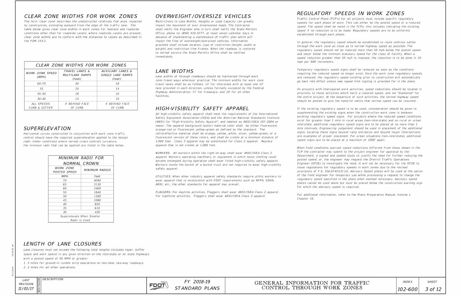
CLEAR ZONE WIDTHS FOR WORK ZONES
CLEAR ZONE WIDTHS FOR WORK ZONES
SUPERELEVATION
LENGTH OF LANE CLOSURES
LANE WIDTHS
OVERWEIGHT/OVERSIZE VEHICLES
NORMAL CROWN
MINIMUM RADII FOR
(MPH)
WORK ZONE SPEED
(feet)
SINGLE LANE RAMPS
AUXILIARY LANES &
MINIMUM RADIUS
(feet)
MULTILANE RAMPS
TRAVEL LANES &
the minimum radii that can be applied are listed in the table below.
radii. Under conditions where normal crown controls curvature,
control should have the required superelevation applied to the design
Horizontal curves constructed in conjunction with work zone traffic
immediately.
to normal service the State Permits Office shall be notified
weight) and restriction time frames. When the roadway is restored
provided shall include location, type of restriction (height, width or
impact the flow of overweight/oversized vehicles. Information
advance of implementing a maintenance of traffic plan which will
Office, phone no. (850) 410-5777, at least seven calendar days in
shall notify the Engineer who in turn shall notify the State Permits
impact the movement of over dimensioned loads. The Contractor
Restrictions to Lane Widths, Heights or Load Capacity can greatly
facilities.
Highway Administration; 11' for freeways; and 10' for all other
lane provided in each direction, unless formally excepted by the Federal
travel lanes shall be as follows: 11' for Interstate with at least one 12'
zone travel ways wherever practical. The minimum widths for work zone
Lane widths of through roadways should be maintained through work
MPH feet
65
60
55
50
45
40
35
30 430
610
820
1080
1390
1840
2400
3130
Radii is Used
Superelevate When Smaller
OF CURB
4' BEHIND FACE
OF CURB
4' BEHIND FACE
CURB & GUTTER
ALL SPEEDS
10
10
14
14
18
24
30 1860-70
55
45-50
30-40
HIGH-VISIBILITY SAFETY APPAREL
REGULATORY SPEEDS IN WORK ZONES
POSTED SPEED
WORK ZONE
Chapter 10.
For additional information, refer to the Plans Preparation Manual, Volume I,
for which the advisory speed is required.
plates cannot be used alone but must be placed below the construction warning sign
regulatory speed specified in the plans when deemed necessary. Advisory speed
of the field engineer for temporary use while processing a request to change the
provisions of F.S. 316.07451(2) (b). Advisory Speed plates will be used at the option
issue regulations for regulatory speeds in work zones due to the revised
Engineer (DTOE) to investigate the need. It will not be necessary for the DTOE to
posted speed, or, the engineer may request the District Traffic Operations
Department, a signed and sealed study to justify the need for further reducing the
TCP the contractor may submit to the project engineer for approval by the
When field conditions warrant speed reductions different from those shown in the
speed signs are to be placed at a maximum of 1000' apart.
are examples of proper placement. For urban situations (non-interstate), additional
signs. Locating these signs beyond ramp entrances and beyond major intersections
mile intervals. Engineering judgement should be used in placement of the additional
interstate, additional regulatory speed signs are to be placed at no more than 1
exist for greater than 1 mile in rural areas (non-interstate) and on rural or urban
existing regulatory speed signs. For projects where the reduced speed conditions
supplementing the existing signs when the construction work zone is between
If the existing regulatory speed is to be used, consideration should be given to
should be posted to give the motorist notice that normal speed can be resumed.
the entire project. At the departure of such activities, the normal highway speed
proximity to those activities which merit a reduced speed, and not "blanketed" for
On projects with interspaced work activities, speed reductions should be located in
go back into effect unless new speed limit signing is provided for in the plans.
are removed, the regulatory speed existing prior to construction will automatically
requiring the reduced speed no longer exist. Once the work zone regulatory speeds
Temporary regulatory speed signs shall be removed as soon as the conditions
mph per 500' increments.
speed reduction greater than 10 mph is imposed, the reduction is to be done in 10
and never below the minimum statutory speed for the class of facility. When a
regulatory speed should not be reduced more than 10 mph below the posted speed
through the work zone as close as to normal highway speed as possible. The
In general, the regulatory speed should be established to route vehicles safely
established through each phase.
speed if no reduction is to be made. Regulatory speeds are to be uniformly
speed. The speed shall be noted in the TCPs; this includes indicating the existing
speeds for each phase of work. This can either be the posted speed or a reduced
Traffic Control Plans (TCP's) for all projects must include specific regulatory
For nighttime activities, Flaggers shall wear ANSI/ISEA Class 3 apparel.
FLAGGERS: For daytime activities, Flaggers shall wear ANSI/ISEA Class 2 apparel.
ANSI, etc., the other standards for apparel may prevail.
wear apparel that is inconsistent with FDOT requirements such as NFPA, OSHA,
UTILITIES: When other industry apparel safety standards require utility workers to
safety apparel.
Workers inside the bucket of a bucket truck are not required to wear high-visibility
become entangled during operation shall wear fitted high-visibility safety apparel.
apparel. Workers operating machinery or equipment in which loose clothing could
WORKERS: All workers within the right-of-way shall wear ANSI/ISEA Class 2
apparel that is not visible at 1,000 feet.
1,000 feet. Class 3 apparel may be substituted for Class 2 apparel. Replace
fluorescent version of these colors, and shall be visible at a minimum distance of
retroreflective material shall be orange, yellow, white, silver, yellow-green, or a
orange-red or fluorescent yellow-green as defined by the standard. The
newer. The apparel background (outer) material color shall be either fluorescent
(ANSI) for "High-Visibility Safety Apparel", and labeled as ANSI/ISEA 107-2004 or
Safety Equipment Association (ISEA) and the American National Standards Institute
All high-visibility safety apparel shall meet the requirements of the International
409070
2. 2 miles for all other operations.
1. 3 miles for ground-in rumble strip operations on two-lane, two-way roadways.
with a posted speed of 55 MPH or greater:
space and work space) in any given direction on the interstate or on state highways
Lane closures must not exceed the following total lengths (includes taper, buffer
the FDM 215.2.
clear zone widths are to conform with the distances to canals as described in
conditions other than for roadside canals; where roadside canals are present,
table below gives clear zone widths in work zones for medians and roadside
by construction, extending outward from the edge of the traffic lane. The
The term 'clear zone' describes the unobstructed relatively flat area, impacted
10/30/2017
9:3
6:4
4
AM
RE
VISIO
N DESCRIPTION:
REVISION
LAST
ofSTANDARD PLANS
FY 2018-19 SHEETINDEX
11/01/17 CONTROL THROUGH WORK ZONESGENERAL INFORMATION FOR TRAFFIC
102-600 4 12
FLAGGER CONTROL
SURVEY WORK ZONES
Hand-Signaling Devices
Flagger Stations
or Shared Left Turn Lanes
Survey Between Active Traffic Lanes
background.
Flagger's high-visibility safety apparel and equipment and the work area
site. Flaggers shall be positioned to maintain maximum color contrast between the
permit traffic to reduce speed or to stop as required before entering the work
to permit proper response by the motorist to the flagging instructions, and to
The flagger must be clearly visible to approaching traffic for a distance sufficient
WORKERS symbol or legend sign.
Where flaggers are used, a FLAGGER symbol or legend sign must replace the
work space. When used at nighttime, the flagger station shall be illuminated.
approaching road users will have sufficient distance to stop before entering the
Flagger stations shall be located far enough in advance of the work space so that
conditions when the Survey Work Zone includes intersections.
provisions must be adjusted by the Party Chief to fit roadway and traffic
The following provisions apply to Main Roadway Traffic Control Work Zones. These
the flow of traffic.
equipment, and up to 50' intervals for at least 200' in both directions towards
to protect the backsight tripod and/or instrument. Cones shall be placed at the
Horizontal Control-With traffic flow in opposite directions, cones shall be used (D)
equipment, and up to 50' intervals for at least 200' towards the flow of traffic.
to protect the backsight tripod and/or instrument. Cones shall be placed at the
Horizontal Control-With traffic flow in the same direction, cones shall be used (C)
intervals along the break line throughout the work zone.
protect prism holder and flagger(s). Cones, if used, may be placed at up to 50'
Elevation Surveys-Cones may be used at the discretion of the Party Chief to (B)
Sign sequence as the second most immediate sign from the work area.
A STAY IN YOUR LANE (MOT-1-06) sign shall be added to the Advance Warning (A)
SIGN MATERIALS
INTERSECTING ROAD SIGNING
ADJOINING AND/OR OVERLAPPING WORK ZONE SIGNING
SIGN COVERING AND INTERMITTENT WORK STOPPAGE SIGNING
PROJECT INFORMATION SIGN
END ROAD WORK SIGN
GROOVED PAVEMENT AHEAD SIGN
LENGTH OF ROAD WORK SIGN
UTILITY WORK AHEAD SIGN
EXTENDED DISTANCE ADVANCE WARNING SIGN
SIGNING FOR DETOURS, LANE SHIFTS AND DIVERSIONS
highway.
AHEAD or the ROAD WORK XX FT (W20-1) sign for utility operations on or adjacent to a
The UTILITY WORK AHEAD (W21-7) sign may be used as an alternate to the ROAD WORK
The Project information sign shall be installed when called for in the plans.
SPEEDING FINES DOUBLED WHEN WORKERS PRESENT SIGN
Sign covers are incidental to work operations and are not paid for separately.
movement.
coverings shall be the same size as the sign it is covering, and bolted in a manner to prevent
Sign blanks or other available coverings must completely cover the existing sign. Rigid sign
with intended travel paths shall be removed or fully covered.
Existing or temporary traffic control signs that are no longer applicable or are inconsistent
signed as a lane shift.
should be used for the advanced warning for a lane shift. A diversion should be
determine how to return to the original roadway. The reverse curve (W1-4) warning sign
Detours should be signed clearly over their entire length so that motorists can easily
vehicle speed is generally in the higher range (45 MPH or more).
any type roadway, but particularly be considered on multilane divided highways where
their vehicle to a stop. Extended distance Advanced Warning Signs may be required on
limited sight distance or the nature of the obstruction may require a motorist to bring
Advance Warning Signs shall be used at extended distance of one-half mile or more when
points.
should be rounded up to the nearest mile. The sign shall be located at begin construction
required for all projects of more than 2 miles in length. The number of miles entered
The length of road work sign (G20-1) bearing the legend ROAD WORK NEXT_____ MILES is
whichever is less.
should be 500 feet beyond the ROAD WORK AHEAD sign or midway to the next sign
projects, but may be omitted if the work operation is less than 1 day. The placement
The SPEEDING FINES DOUBLED WHEN WORKERS PRESENT sign should be installed on all
Index 102-600, ADJOINING AND/OR OVERLAPPING WORK ZONE SIGNING.
within 1 mile this sign should be omitted and signing coordinated in accordance with
is called for in the plans. When other Construction or Maintenance Operations occur
500 feet beyond the end of a construction or maintenance project unless other distance
where the work operation is less than 1 day. The sign should be placed approximately
The END ROAD WORK sign (G20-2) should be installed on all projects, but may be omitted
highway construction projects.
and/or permitted work; and, between unit controlled maintenance works and
maintenance works; between routine maintenance work, unscheduled work
The Unit Maintenance Engineer will resolve conflicts that occur within routine (D)
conflicts within scheduled maintenance operations.
The District Maintenance Engineer will resolve anticipated and occurring (C)
progress projects under adjoining residencies.
under his residency, and, by the District Construction Engineer for in
construction projects will be resolved by the Resident Engineer for projects
Unanticipated conflicts arising between adjoining in progress highway (B)
projects and coordination of plans on concurrent projects.
project traffic control plan. This may entail revision of plans on preceding
will resolve anticipated work zone conflicts during the development of the
For scheduled projects the engineer in responsible charge of project design (A)
procedure applied:
part of the traveling public as to the intended travel way by the traffic control
to avoid conflicts and prevent conditions that could lead to misunderstanding on the
conflicts occur or are likely to occur, one of the following methods will be employed
cases other areas within their traffic control zones. Where such restraints or
signs and other traffic control devices in their advance warning areas or in some
Adjoining work zones may not have sufficient spacing for standard placement of
the GROOVED PAVEMENT AHEAD sign.
grooved surface open to traffic. The W8-15P placard shall be used in conjuction with
The GROOVED PAVEMENT AHEAD sign is required 500 feet in advance of a milled or
SIGNS
sign on the side street entering the work zone.
conditions. When Work operations exceed 60 minutes, place the ROAD WORK AHEAD
intersecting crossroads shall be adequate to make drivers aware of work zone
Signing for the control of traffic entering and leaving work zones by way of
be used at night.
Flashlight, lantern or other lighted signal that will display a red warning light shall
nighttime, flags shall be retroreflectorized red.
fastened to a staff that is approximately 36 inches in length. When used at
minimum of 24 inches square, made of a good grade of red material, and securely
there is opposing traffic in the adjacent lanes. Flags, when used, shall be a
the centerline or shared left turn lanes where two (2) flaggers are required and
Flag use is limited to immediate emergencies, intersections, and when working on
used at night-time, the STOP/SLOW paddle shall be retroreflectorized.
background of the SLOW face shall be orange with black letters and border. When
background of the STOP face shall be red with white letters and border. The
6 inches high and should be fabricated from light semirigid material. The
than 6 ft. STOP/SLOW paddles shall be at least 24 inches wide with letters at least
of the paddle to the end of the staff that rests on the ground, must not be less
placed on a rigid staff, the minimum length of the staff, measured from the bottom
shall have an octagonal shape on a rigid handle. If the STOP/SLOW paddle is
STOP/SLOW paddles are the primary hand-signaling device. The STOP/SLOW paddle
drawing for the sign stand to which they are attached.
Rigid or Lightweight sign panels may be used in accordance with the vendor APL
in the Indexes.
may be used for daylight or night operations not to exceed 1 day except as noted
Retroreflective vinyl signs meeting the requirements of Specification Section 994
Specifications Section 994.
operations. Non-retroreflectice vinyl signs must meet the requirements of
Mesh signs and non-retroreflectice vinyl signs may only be used for daylight
omitted.
the END ROAD WORK sign as called for on certain 102 Series of Indexes should be
When Traffic Control Through Work Zones is being used for survey purposes only,
Party Chief.
the ROAD WORK AHEAD sign when lane closures occur, at the discretion of the
Warning Sign used for Traffic Control Through Survey Work Zones and may replace
The SURVEY CREW AHEAD symbol or legend sign shall be the principal Advance
10/30/2017
9:3
6:4
5
AM
RE
VISIO
N DESCRIPTION:
REVISION
LAST
ofSTANDARD PLANS
FY 2018-19 SHEETINDEX
CONTROL THROUGH WORK ZONESGENERAL INFORMATION FOR TRAFFIC
102-600 5 1211/01/17
Sign
Head Bolt
" Steel Hex165
" Nominal Size)165(
Lock Washer
" Steel Hex Nut165
"Ø @ 1" Centers83
Cutting Edge
Surface
Ground
Ground SurfaceSteel U-Channel Posts
Shoulder
Paved
Elevation
Travelway
Edge Of
¡ Sign
(At ¡ Post)
1" Min. 6" Max (Typ.)
Shoulder
Paved
Elevation
Travelway
Edge Of
Ground Surface
Bottom Of Sign
Steel U-Channel Posts
Nuts & Washers (Typ.)
"Ø Bolts,1652-
Nuts & Washers (Typ.)
"Ø Bolts,1652-
Bottom Of Sign
Steel U-Channel Posts
Curb & Gutter Walkway
1'-6" (± 3") for 36" Wide Signs; 2'-6" (± 6") Typ. For Others
" Nominal Size) 165(
Flat Washer
Steel U-Channel Post
For Base Post Only
Stub Height 4" Max. Base Post
Sign Post Or
(At ¡ Post)
1" Min. 6" Max (Typ.)
¡ Sign ¡ Sign
(At ¡ Post)
1" Min. 6" Max (Typ.)
Speeding fines
doubled
when workers
present
500 FT
work
500 FT
ROADROAD
WORK
(WITHOUT Z-BRACKET)
SIGN ATTACHMENT DETAIL
(SCHEMATIC)
SECTION A-A
3 POST SIGN SUPPORT MOUNTING DETAILS
TYPICAL FOUNDATION DETAIL
URBAN
(SINGLE POST SIMILAR)
2 POST SIGN SUPPORT MOUNTING DETAILS
RURAL
(SINGLE POST SIMILAR)
2 POST SIGN SUPPORT MOUNTING DETAILS
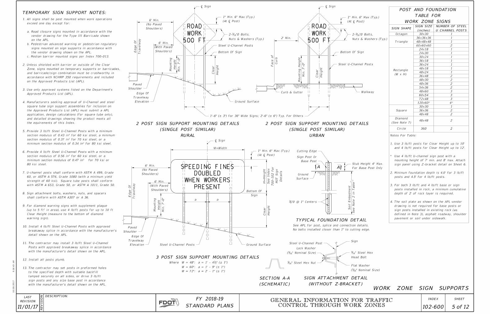
AA
WORK ZONE SIGNS
TABLE FOR
POST AND FOUNDATION
pavement or soil under sidewalk.
defined in Note 3), asphalt roadway, shoulder
sign posts installed in existing rock (as
drawing is not required for base posts or
The soil plate as shown on the APL vendor 4.
depth of 2' of rock layer is required.
posts installed in rock, a minimum cumulative
For both 3 lb/ft and 4 lb/ft base or sign 3.
posts and 4.5' for 4 lb/ft posts.
Minimum foundation depth is 4.0' for 3 lb/ft 2.
sign panel using Z-bracket detail on Sheet 6.
mounting height of 7' min. and 8' max. Attach
Use 4 lb/ft U-channel sign post with a *
and 4 lb/ft posts for Clear Height up to 12'.
Use 3 lb/ft posts for Clear Height up to 10' 1.
Notes For Table:
U CHANNEL POSTS
NUMBER OF STEEL
(inches)
SIGN SIZESIGN SHAPE
(W x H)
Rectangle
Triangle
Octagon 30x30
36x36x36
48x48x48
60x60x60
24x18
24x30
30x24
36x18
48x18
36x48
48x30
48x36
54x36
48x60
72x48
30x30
36x36
48x48
48x48
36ØCircle
Square
2
2
2
2
1
4*
3
3
3
2
2
2
2
1
1
1
1
1
1
2
1
1
1
36x24
60x54
120x60*
(See Note 7)
Diamond
Shoulders)
(No Paved
6' Min.
Travelw
ay
Edge
Of
Shoulders)
(With Paved
6' Min.
Heig
ht
Cle
ar
2' Min.
Heig
ht
Cle
ar
W=Width
a a
Heig
ht
Cle
ar
Travelw
ay
Edge
Of
Shoulders)
(No Paved
6' Min.
Shoulders)
(With Paved
6' Min.
Sign
Bottom Of
See
Note 2 in Table
Soil E
mbed
ment
No bolts installed closer than 1" to cutting edge.
See APL for post, splice and connection details.
W = 72": a = 2' - 1" (± 1")
W = 60": a = 1' - 9" (± 1")
" (± 1")21W = 48": a = 1' - 4Where
Min.
7'-
0"
Heig
ht
Mountin
g
Min.
7'-
0"
Heig
ht
Mountin
g
Min.
7'-
0"
Mountin
g
Heig
ht
Curb
Face of
WORK ZONE SIGN SUPPORTS
148x24
Details
MO
T Sig
n
700-102 for
See Index
H=
Heig
ht
TEMPORARY SIGN SUPPORT NOTES:
with the manufacturer's detail shown on the APL.
sign posts and any size base post in accordance
tamped securely on all sides, or drive 3 lb/ft
to the specified depth with suitable backfill
13. The contractor may set posts in preformed holes
12. Install all posts plumb.
with the manufacturer's detail shown on the APL.
Posts with approved breakaway splice in accordance
11. The contractor may install 3 lb/ft Steel U-Channel
detail shown on the APL.
breakaway splice in accordance with the manufacturer's
10. Install 4 lb/ft Steel U-Channel Posts with approved
warning sign).
Clear Height (measure to the bottom of diamond
(up to 5 ft² in area), use 4 lb/ft posts for up to 10 ft
9. For diamond warning signs with supplement plaque
shall conform with ASTM A307 or A 36.
8. Sign attachment bolts, washers, nuts, and spacers
with ASTM A 653, Grade 50, or ASTM A 1011, Grade 50.
strength of 60 ksi). Square tube posts shall conform
60, or ASTM A 576, Grade 1080 (with a minimum yield
7. U-channel posts shall conform with ASTM A 499, Grade
80 ksi steel.
minimum section modulus of 0.47 in³ for 70 ksi or
section modulus of 0.56 in³ for 60 ksi steel, or a
6. Provide 4 lb/ft Steel U-Channel Posts with a minimum
minimum section modulus of 0.34 in³ for 80 ksi steel.
section modulus of 0.37 in³ for 70 ksi steel, or a
section modulus of 0.43 in³ for 60 ksi steel, a minimum
5. Provide 3 lb/ft Steel U-Channel Posts with a minimum
the equirements of this Index.
and detailed drawings showing the product meets all
application, design calculations (for square tube only),
the Approved Products List (APL) must submit a APL
square tube sign support assemblies for inclusion on
4. Manufacturers seeking approval of U-Channel and steel
Approved Products List (APL).
3. Use only approved systems listed on the Department's
on the Approved Products List (APL).
accordance with NCHRP 350 requirements and included
and barricade/sign combination must be crashworthy in
Zone, signs mounted on temporary supports or barricades,
2. Unless shielded with barrier or outside of the Clear
c. Median barrier mounted signs per Index 700-013.
the vendor drawing shown on the APL.
signs mounted on sign supports in accordance with
b. Pedestrian advanced warning or pedestrian regulatory
on the APL.
vendor drawing for the Type III Barricade shown
a. Road closure signs mounted in accordance with the
exceed one day except for:
1. All signs shall be post mounted when work operations

10/30/2017
9:3
6:4
6
AM
RE
VISIO
N DESCRIPTION:
REVISION
LAST
ofSTANDARD PLANS
FY 2018-19 SHEETINDEX
5'-
0"
10'-0"
4.2"
6"D
4"
4"D
4"0.8"4"
6"D
4"0.8"4"
4"D
4"
6"D
4.2"
IN=0.75"
TH=0.25"
R=8"
BORDER
IN=0.75"
TH=0.25"
R=3"
BORDER
4"
6"C
5"
4"D
5"
6"C
5"
4"D
5"
6"C
4"
5'-0"
4'-
6"
-
SR XXX SR XXX
SEASON YEAR
1-XXX-XXX-XXXX
* *
*-See Note 1.
1-XXX-XXX-XXXX
CONTRACTOR
SEASON YR.
11/01/17 6 12
RE
VISIO
N DESCRIPTION:
REVISION
LAST
CONTROL THROUGH WORK ZONESGENERAL INFORMATION FOR TRAFFIC
102-600
x1.0943x14
3Aluminum Z 1
With Nuts and Lock Washers.
" Galvanized Steel Bolts165
Sign Post
4 lb/ft U-Channel
x1.0943x14
3Aluminum Z 1
-
-
Of Sign
Bottom
Elevation
Travelway
Edge Of
Surface
Ground Sign Post
4 lb/ft U-Channel
Strip Details
for Backing
See Index 11200
Optional Splice:
" Thick Aluminum8
1
Sign Panel
With Nuts and Lock Washers
" Galvanized Steel Bolts165
And Lock Washers
Machine Bolt With Nuts
" Aluminum Flat Head41
(Typ) Bolt spacing ± 1"
With Nut and Washer
Head Machine Bolt
" Ø Aluminum Flat 4
1
PROJECT INFORMATION SIGN NOTES:
(WITH Z-BRACKET)
SIGN ATTACHMENT DETAIL
45 MPH OR LESS
PROJECT INFORMATION SIGN DETAIL
50 MPH OR GREATER
PROJECT INFORMATION SIGN DETAIL
4 POST SIGN SUPPORT MOUNTING DETAIL
BRACKET DETAIL
9'-2"
Z Bracket Wind Beam Length
3" 3" 3" 5"
1"
5'-
0"
3'-
0"
1'-
0"
1'-
0"
"211'-1 2'-7" 2'-7" 2'-7" "2
11'-1
10'-0"
White Legend and Border
Blue Background
4" and 6" series D Legend
8" Radii
10'-0"x 5'-0"
On Sheet 5.
(WITHOUT Z-BRACKET)
Use SIGN ATTACHMENT DETAIL
(WITH Z-BRACKET).
Use SIGN ATTACHMENT DETAIL
White Legend and Border
Blue Background
6" series C Legend
4" series D Legend and
3" Radii
5'-0"x 4-6"
PROJECT INFORMATION SIGN
7'
Min.; 8'
Max.
Mountin
g
Heig
ht
3" 3"3 Eq. Sp.= 2'-7" ± 1"
and Foundations Table.
See Sheet 5 for Typical Foundation Details and Post 3.
specific to the project.
2. Italic text on signs indicate variable information
designation (ie. I-Interstate, SR-State Road or US.)
Road designation should be the most common 1.
10/30/2017
9:3
6:4
6
AM
RE
VISIO
N DESCRIPTION:
REVISION
LAST
ofSTANDARD PLANS
FY 2018-19 SHEETINDEX GENERAL INFORMATION FOR TRAFFIC
CONTROL THROUGH WORK ZONES
7 12
RE
VISIO
N DESCRIPTION:
REVISION
LAST
11/01/17 102-600
OM-3R
B/Y
R1-1
W/R
R4-7
B/W
R4-8
B/W
W3-2
RB/ORB/O
W3-1
B/O
W1-8
B/O
W1-7
B/O
W1-6
B/O
W1-4c
B/O
W1-4bW1-4R
B/OB/O
W1-3RW1-2R
B/O
W6-3
B/O
B/O
W1-1R
W6-1
B/O B/O
W6-2
WR/W
R5-1
B/O
W4-2
B/O
W4-1
B/O
W12-1
B/O
W11-2
W16-7P
B/O
B/O
W20-7
B/O
W21-1
DETOUR
M4-9L
B/O
DETOUR
M4-9R
B/O
DETOUR
M4-10L
O/B
DETOUR
M4-10R
O/B
YIELD
R1-2
RW/R
SPEED
LIMIT
XX
R2-1
B/W
DO
NOT
PASS
R4-1
B/W
PASS
WITH
CARE
R4-2
B/W
TRUCKS
USE
CENTER
LANE
R4-5
B/W
KEEP
LEFT
R4-7AL
B/W
GKO
B/O
W8-5
DROP OFF
SHOULDER
B/O
W8-9a
ENDS
PAVEMENT
W8-3
B/O
SIDEWALK CLOSED
CROSS HERE
B/W
R9-11a
KEEP
LEFT
B/W
R4-7BL
KEEP
RIGHT
B/W
R4-7BR
USE OTHER SIDE
SIDEWALK CLOSED
R9-10
B/W
AHEAD
SIDEWALK CLOSED
CROSS HERE
R9-11
B/W
SPEED
LIMIT
XX
W3-5
B/O
TO STOP
PREPARED
BE
B/O
W3-4
KEEP
RIGHT
B/W
R4-7AR
R
Y
G
W3-3
B(RYG)/O
M.P.H.
XX
B/O
W13-1
12'-6"
B/O
W12-2
RR
B/Y
W10-1
LANES
UNEVEN
B/O
W8-11
TURN OFF
CELL PHONE
AND
2-WAY RADIO
B/O
W22-2
B/O
W22-1
DETOUR
MILE1
2
B/O
W20-2E
ROAD
MILE1
2
WORK
B/O
W20-1D
CLOSED
SHOULDER
RIGHT
B/O
W21-5a
PEDESTRIAN
WALKWAY
B/W
MOT-12-06L
PEDESTRIAN
WALKWAY
B/W
MOT-12-06R
BUSINESS
ENTRANCE
BLUE/W
MOT-11-06
AHEAD
STRIPS
RUMBLE
MOT-18-10
B/O
AHEAD
PAVEMENT
GROOVED
MOT-15-06
B/O
(All other facilities)
MOT-14-06
(Limited access facilities)
MOT-13-06
PRESENT
SPEEDING FINES
DOUBLED
WHEN WORKERS
Slow Down
My Mommy
Works Here
MOT-17-06
B/O
Slow Down
My Daddy
Works Here
MOT-16-06
B/O
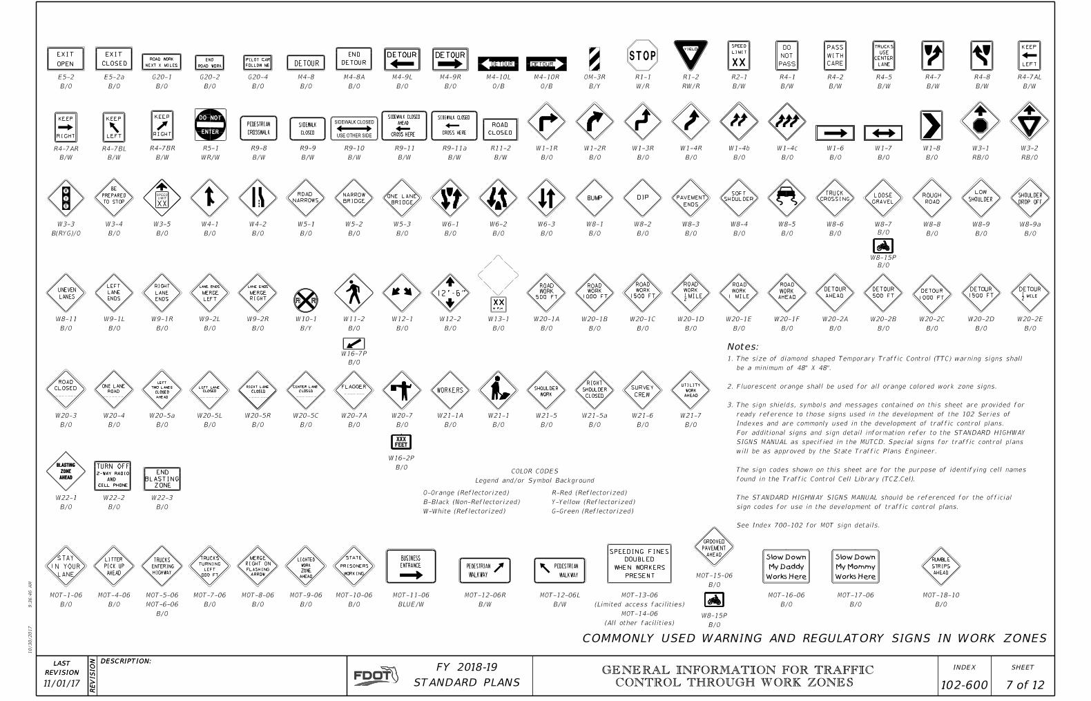
COMMONLY USED WARNING AND REGULATORY SIGNS IN WORK ZONES
Notes:
W-White (Reflectorized)
B-Black (Non-Reflectorized)
O-Orange (Reflectorized)
G-Green (Reflectorized)
Y-Yellow (Reflectorized)
R-Red (Reflectorized)
Legend and/or Symbol Background
COLOR CODES
OPEN
EXIT
E5-2
B/O
CLOSED
EXIT
E5-2a
B/O
NEXT X MILES
ROAD WORK
G20-1
B/O
ROAD WORK
END
G20-2
B/O
FOLLOW ME
PILOT CAR
G20-4
B/O
DETOUR
M4-8
B/O
END
DETOUR
M4-8A
B/O
SOFT
SHOULDER
B/O
W8-4
TRUCK
CROSSING
B/O
W8-6
LOOSE
GRAVEL
B/O
W8-7
ROUGH
ROAD
B/O
W8-8
LOW
SHOULDER
B/O
W8-9
W8-15P
B/O
DIP
B/O
W8-2
BUMP
B/O
W8-1
ROAD
CLOSED
R11-2
B/W
CROSSWALK
PEDESTRIAN
R9-8
B/W
SIDEWALK
CLOSED
R9-9
B/W
BRIDGE
ONE LANE
B/O
W5-3
NARROW
BRIDGE
B/O
W5-2
ROAD
NARROWS
B/O
W5-1
ROAD
500 FT
WORK
B/O
W20-1A
MERGE
RIGHT
LANE ENDS
B/O
W9-2R
MERGE
LEFT
LANE ENDS
B/O
W9-2L
LANE
ENDS
RIGHT
B/O
W9-1R
LANE
ENDS
LEFT
B/O
W9-1L
ROAD
CLOSED
B/O
W20-3
ONE LANE
ROAD
B/O
W20-4
TWO LANES
CLOSED
AHEAD
LEFT
W20-5a
B/O B/O
W20-5L
CLOSED
RIGHT LANE
B/O
W20-5R
CLOSED
CENTER LANE
B/O
W20-5C
FLAGGER
B/O
W20-7A
WORKERS
B/O
W21-1A
SHOULDER
WORK
B/O
W21-5
W16-2P
B/OEND
BLASTING
ZONE
B/O
W22-3
DETOUR
1500 FT
B/O
W20-2D
DETOUR
1000 FT
B/O
W20-2C
DETOUR
500 FT
B/O
W20-2B
DETOUR
AHEAD
B/O
W20-2A
ROAD
AHEAD
WORK
B/O
W20-1F
ROAD
1 MILE
WORK
B/O
W20-1E
ROAD
1500 FT
WORK
B/O
W20-1C
ROAD
1000 FT
WORK
B/O
W20-1B
UTILITY
WORK
AHEAD
W21-7
B/O
SURVEY
CREW
B/O
W21-6
STATE
PRISONERS
WORKING
B/O
MOT-10-06
LIGHTED
ZONE
AHEAD
WORK
B/O
MOT-9-06
MERGE
RIGHT ON
ARROW
FLASHING
B/O
MOT-8-06
TRUCKS
TURNING
LEFT
000 FT
B/O
MOT-7-06
TRUCKS
ENTERING
HIGHWAY
B/O
MOT-6-06
MOT-5-06
LITTER
PICK UP
AHEAD
B/O
MOT-4-06
STAY
LANE
lN YOUR
B/O
MOT-1-06
W8-15P
B/O
LEFT LANE
CLOSED
See Index 700-102 for MOT sign details.
sign codes for use in the development of traffic control plans.
The STANDARD HIGHWAY SIGNS MANUAL should be referenced for the official
found in the Traffic Control Cell Library (TCZ.Cel).
The sign codes shown on this sheet are for the purpose of identifying cell names
will be as approved by the State Traffic Plans Engineer.
SIGNS MANUAL as specified in the MUTCD. Special signs for traffic control plans
For additional signs and sign detail information refer to the STANDARD HIGHWAY
Indexes and are commonly used in the development of traffic control plans.
ready reference to those signs used in the development of the 102 Series of
The sign shields, symbols and messages contained on this sheet are provided for 3.
Fluorescent orange shall be used for all orange colored work zone signs.2.
be a minimum of 48" X 48".
The size of diamond shaped Temporary Traffic Control (TTC) warning signs shall 1.
10/30/2017
9:3
6:4
7
AM
RE
VISIO
N DESCRIPTION:
REVISION
LAST
ofSTANDARD PLANS
FY 2018-19 SHEETINDEX GENERAL INFORMATION FOR TRAFFIC
CONTROL THROUGH WORK ZONES
8 12
11/01/17 102-600
above ground obstruction
Manhole or other Asphalt Apron
Temporary Surface501
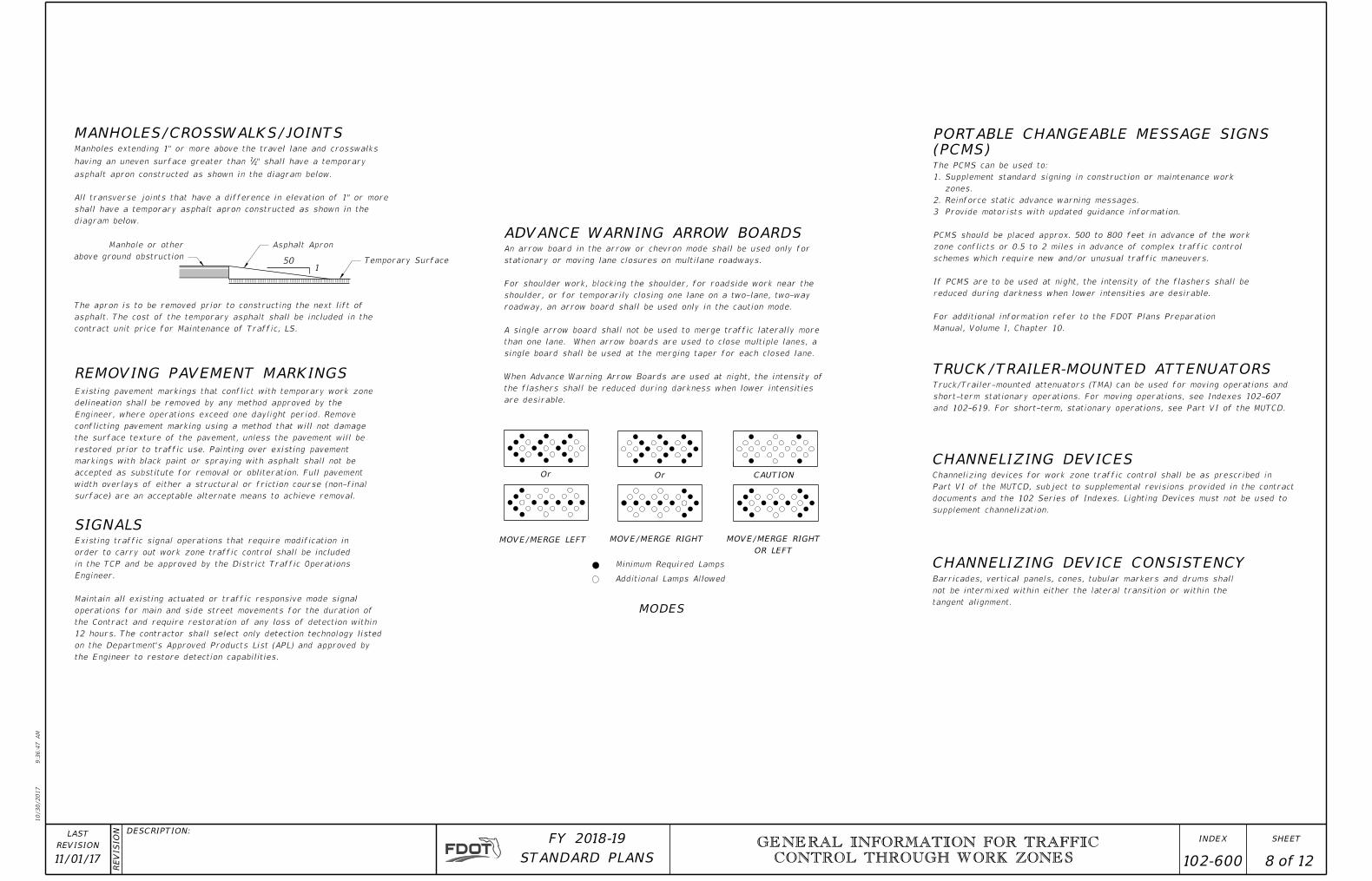
MANHOLES/CROSSWALKS/JOINTS
TRUCK/TRAILER-MOUNTED ATTENUATORSREMOVING PAVEMENT MARKINGS
SIGNALS
ADVANCE WARNING ARROW BOARDS
MODES
MOVE/MERGE LEFT MOVE/MERGE RIGHT
CAUTIONOrOr
diagram below.
shall have a temporary asphalt apron constructed as shown in the
All transverse joints that have a difference in elevation of 1" or more
asphalt apron constructed as shown in the diagram below.
" shall have a temporary41having an uneven surface greater than
Manholes extending 1" or more above the travel lane and crosswalks
contract unit price for Maintenance of Traffic, LS.
asphalt. The cost of the temporary asphalt shall be included in the
The apron is to be removed prior to constructing the next lift of
tangent alignment.
not be intermixed within either the lateral transition or within the
Barricades, vertical panels, cones, tubular markers and drums shall
are desirable.
the flashers shall be reduced during darkness when lower intensities
When Advance Warning Arrow Boards are used at night, the intensity of
single board shall be used at the merging taper for each closed lane.
than one lane. When arrow boards are used to close multiple lanes, a
A single arrow board shall not be used to merge traffic laterally more
roadway, an arrow board shall be used only in the caution mode.
shoulder, or for temporarily closing one lane on a two-lane, two-way
For shoulder work, blocking the shoulder, for roadside work near the
stationary or moving lane closures on multilane roadways.
An arrow board in the arrow or chevron mode shall be used only for
Additional Lamps Allowed
Minimum Required Lamps
OR LEFT
MOVE/MERGE RIGHT
Manual, Volume I, Chapter 10.
For additional information refer to the FDOT Plans Preparation
reduced during darkness when lower intensities are desirable.
If PCMS are to be used at night, the intensity of the flashers shall be
schemes which require new and/or unusual traffic maneuvers.
zone conflicts or 0.5 to 2 miles in advance of complex traffic control
PCMS should be placed approx. 500 to 800 feet in advance of the work
Provide motorists with updated guidance information.3
Reinforce static advance warning messages.2.
zones.
Supplement standard signing in construction or maintenance work 1.
The PCMS can be used to:
(PCMS)
PORTABLE CHANGEABLE MESSAGE SIGNS
CHANNELIZING DEVICES
CHANNELIZING DEVICE CONSISTENCY
the Engineer to restore detection capabilities.
on the Department's Approved Products List (APL) and approved by
12 hours. The contractor shall select only detection technology listed
the Contract and require restoration of any loss of detection within
operations for main and side street movements for the duration of
Maintain all existing actuated or traffic responsive mode signal
Engineer.
in the TCP and be approved by the District Traffic Operations
order to carry out work zone traffic control shall be included
Existing traffic signal operations that require modification in
surface) are an acceptable alternate means to achieve removal.
width overlays of either a structural or friction course (non-final
accepted as substitute for removal or obliteration. Full pavement
markings with black paint or spraying with asphalt shall not be
restored prior to traffic use. Painting over existing pavement
the surface texture of the pavement, unless the pavement will be
conflicting pavement marking using a method that will not damage
Engineer, where operations exceed one daylight period. Remove
delineation shall be removed by any method approved by the
Existing pavement markings that conflict with temporary work zone
and 102-619. For short-term, stationary operations, see Part VI of the MUTCD.
short-term stationary operations. For moving operations, see Indexes 102-607
Truck/Trailer-mounted attenuators (TMA) can be used for moving operations and
supplement channelization.
documents and the 102 Series of Indexes. Lighting Devices must not be used to
Part VI of the MUTCD, subject to supplemental revisions provided in the contract
Channelizing devices for work zone traffic control shall be as prescribed in
10/30/2017
9:3
6:4
8
AM
RE
VISIO
N DESCRIPTION:
REVISION
LAST
ofSTANDARD PLANS
FY 2018-19 SHEETINDEX
11/01/17 CONTROL THROUGH WORK ZONESGENERAL INFORMATION FOR TRAFFIC
102-600 9 12
(When Steeper Than 1:4)
6" Solid Lane Line
Setback Distance
*
*
(See Sheet 11)
Or Temporary Barrier
Channelizing Device
Edge Of Travel Way
Required
Device
(in.)
D
(ft)
X
0-CZ
> 3 to ≤ 5
> 3
> 5
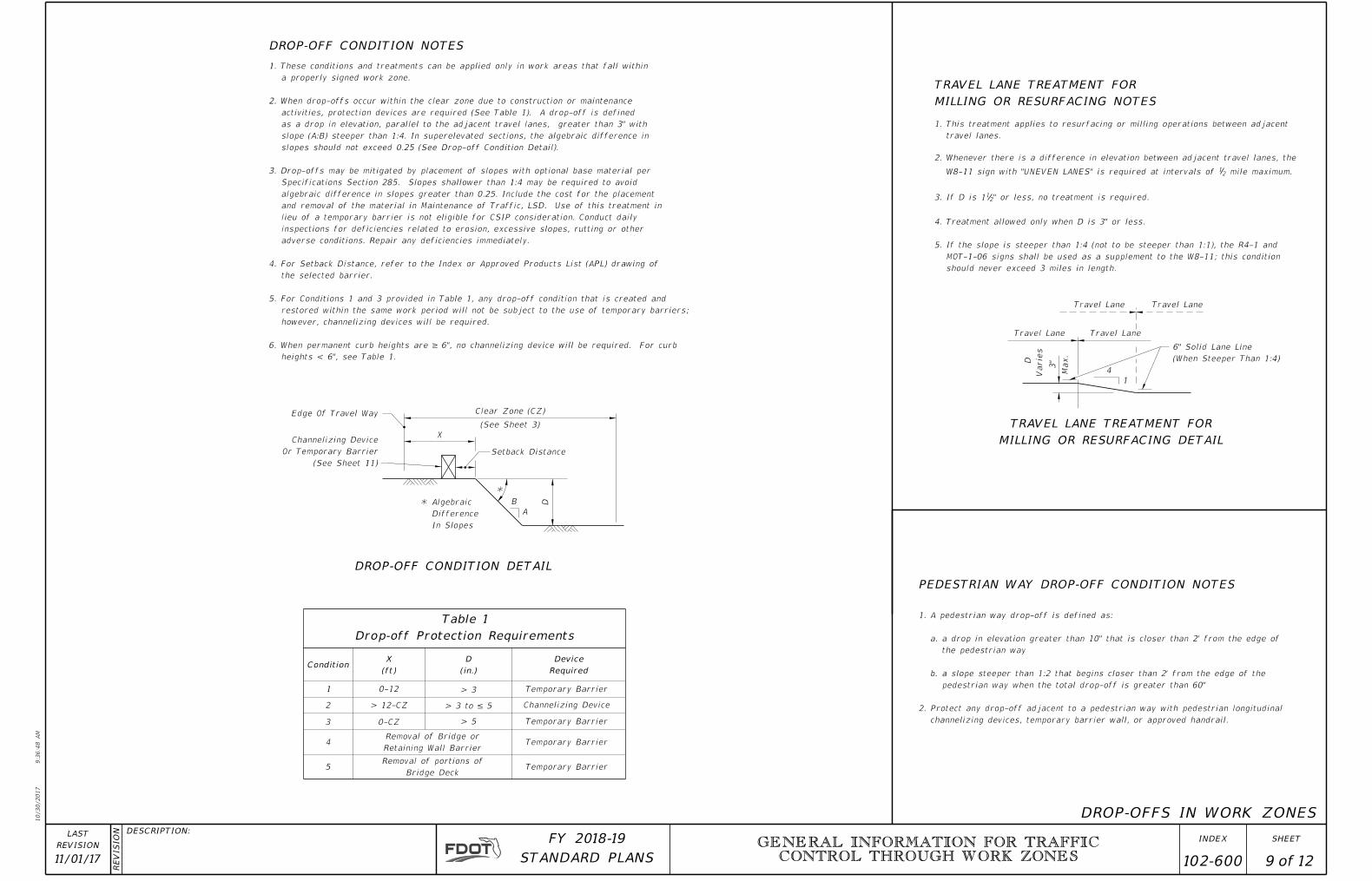
should never exceed 3 miles in length.
MOT-1-06 signs shall be used as a supplement to the W8-11; this condition
If the slope is steeper than 1:4 (not to be steeper than 1:1), the R4-1 and 5.
Treatment allowed only when D is 3" or less.4.
" or less, no treatment is required.21If D is 13.
mile maximum.21W8-11 sign with "UNEVEN LANES" is required at intervals of
Whenever there is a difference in elevation between adjacent travel lanes, the 2.
travel lanes.
This treatment applies to resurfacing or milling operations between adjacent 1.
Clear Zone (CZ)
X
B
A
D
Travel Lane Travel Lane
Travel LaneTravel Lane
4
1
Varie
s
D
3"
Max.
DROP-OFF CONDITION NOTES
Condition
1
2
3
4
5Bridge Deck
Removal of portions of
Drop-off Protection Requirements
Table 1
DROP-OFF CONDITION DETAIL
MILLING OR RESURFACING DETAIL
TRAVEL LANE TREATMENT FOR
MILLING OR RESURFACING NOTES
TRAVEL LANE TREATMENT FOR
Retaining Wall Barrier
Removal of Bridge or
DROP-OFFS IN WORK ZONES
In Slopes
Difference
Algebraic
0-12
> 12-CZ Channelizing Device
PEDESTRIAN WAY DROP-OFF CONDITION NOTES
channelizing devices, temporary barrier wall, or approved handrail.
Protect any drop-off adjacent to a pedestrian way with pedestrian longitudinal 2.
pedestrian way when the total drop-off is greater than 60"
a slope steeper than 1:2 that begins closer than 2' from the edge of the b.
the pedestrian way
a drop in elevation greater than 10" that is closer than 2' from the edge of a.
A pedestrian way drop-off is defined as:1.
heights < 6", see Table 1.
6. When permanent curb heights are ≥ 6", no channelizing device will be required. For curb
however, channelizing devices will be required.
restored within the same work period will not be subject to the use of temporary barriers;
5. For Conditions 1 and 3 provided in Table 1, any drop-off condition that is created and
the selected barrier.
4. For Setback Distance, refer to the Index or Approved Products List (APL) drawing of
adverse conditions. Repair any deficiencies immediately.
inspections for deficiencies related to erosion, excessive slopes, rutting or other
lieu of a temporary barrier is not eligible for CSIP consideration. Conduct daily
and removal of the material in Maintenance of Traffic, LSD. Use of this treatment in
algebraic difference in slopes greater than 0.25. Include the cost for the placement
Specifications Section 285. Slopes shallower than 1:4 may be required to avoid
3. Drop-offs may be mitigated by placement of slopes with optional base material per
slopes should not exceed 0.25 (See Drop-off Condition Detail).
slope (A:B) steeper than 1:4. In superelevated sections, the algebraic difference in
as a drop in elevation, parallel to the adjacent travel lanes, greater than 3" with
activities, protection devices are required (See Table 1). A drop-off is defined
2. When drop-offs occur within the clear zone due to construction or maintenance
a properly signed work zone.
1. These conditions and treatments can be applied only in work areas that fall within
Temporary Barrier
Temporary Barrier
Temporary Barrier
Temporary Barrier
(See Sheet 3)

10/30/2017
9:3
6:4
8
AM
RE
VISIO
N DESCRIPTION:
REVISION
LAST
ofSTANDARD PLANS
FY 2018-19 SHEETINDEX GENERAL INFORMATION FOR TRAFFIC
CONTROL THROUGH WORK ZONES
12
102-600 1011/01/17
Bands
Retroreflectorized
Two 3" White
2"-6" Space
2" R±
Lane Separator
Asphalt (See Note 5)
Channelizing Devices
Fixed (Surface Mounted)
Lane Separator
Asphalt (See Note 5)
(Included In Cost Of Separator)
Painted Reflectorized Yellow
Entire Separator Shall Be
ENTRANCE
BUSINESS
Device Spacing
Table 3
CHANNELIZING DEVICES AT BUSINESS ENTRANCE
PLACEMENT OF BUSINESS ENTRANCE SIGNS AND
CHANNELIZING DEVICES
FIXED (SURFACE MOUNTED)
SECTION AA
PLAN
12"
TEMPORARY LANE SEPARATOR
Divider
Opposing Traffic Lane
Vertical Panels or
Max. Distance Between Devices (ft.)
Tubular Markers(mph)
Speed
TangentTaperTangentTaper
25 50
25
25
50
50
25
30
50 100
30 to 45
50 to 70
25 50
50
Spacing
Standard
Spacing
Reduced
Spacing
Reduced
10'
Std.
40'40'
Std.
10'
Driv
ew
ay
Max
12"
Max
12"
Max
12"
28" to 36"
12"
Base
4"
Max.
2"
Max
" Min.412
B/O
W6-4
Lane Divider
Opposing Traffic
Orange
Tubular Marker
O/W
Vertical Panel
See Table 3
Device Spacing
Max
12"A
A
repaired and the cost of such repairs are to be included in the cost of Maintenance of Traffic, LS.
Any damage to existing pavement caused by the removal of temporary lane separator shall be satisfactorily 6.
separators shall be one of those listed on the Approved Products List.
Portable temporary lane separators shall duplicate the color of the pavement marking. Portable temporary lane
separate curb sections. Each temporary lane separator section shall be 36 inches to 48 inches in total length.
lane separator shall come in portable sections that can be connected to maintain continuous alignment between the
lieu of the temporary asphalt separator and channelizing devices detailed on this sheet. The portable temporary
The Contractor has the option of using portable temporary lane separators containing fixed channelizing devices in 5.
gradual increase in height from the pavement level to the top of the temporary lane separator.
Tapered ends shall be used at the beginning and end of each run of the temporary lane separator to form a 4.
spacing of 25' in areas with grades of 1% or less or 50' in areas with grades over 1% as directed by the Engineer.
12" openings for drainage shall be constructed in the asphalt and portable temporary lane separator at a maximum 3.
and night. Furnish channelizing devices having retroreflective sheeting meeting the requirements of Section 990.
Reflectorized materials shall have a smooth sealed outer surface which will display the same approximate color day 2.
channelizing device and the temporary lane separator curb shall hold the channelizing device in a vertical position.
be intermixed within the limits where the temporary lane separator is used. The connection between the
two-lane, two-way operation. Tubular Markers, Vertical Panels and Opposing Traffic Lane Divider panels shall not
divider panels (W6-4) shall only be used as center lane dividers to separate opposing vehicular traffic on a
channelizing devices: tubular markers, vertical panels, or opposing traffic lane divider panels. Opposing traffic lane
Temporary lane separators shall be supplemented with any of the following approved fixed (surface mounted) 1.
which is often the case with resurfacing type projects.
signs are not required where there is minimal disruption to business driveways
moved/modified or disturbed during construction projects. Business entrance
Business entrance signs are intended to guide motorist to business entrances 4.
driveway entrance, but shall not restrict sight distance for the driveway users.
Channelizing devices shall be placed at a reduced spacing on each side of the 3.
common driveway entrance.
standard BUSINESS ENTRANCE sign in accordance with Index 700-102 at the
When several businesses share a common driveway entrance, place one 24" x 36" 2.
Index 700-102 may be used when approved by the Engineer.
may be provided by business owners. Standard BUSINESS ENTRANCE sign in
driveway entrance affected. Signs shall show specific business names. Logos
For single business entrances, place one 24" x 36" business sign for each 1.
10/30/2017
9:3
6:4
9
AM
RE
VISIO
N DESCRIPTION:
REVISION
LAST
ofSTANDARD PLANS
FY 2018-19 SHEETINDEX GENERAL INFORMATION FOR TRAFFIC
CONTROL THROUGH WORK ZONES
11 12
102-60011/01/17
18" Diameter
4" Diameter
Forklift AccessForklift Access
Of The Edge Of Travel Way
Parallel To And Within 4 Feet
Per Note #11 When Placed
Use Barrier Delineators
Per Note #11
Delineators
Use Barrier
TYPE III BARRICADE
BARRICADE
DIRECTION INDICATOR TYPE II BARRICADETYPE I BARRICADE
VERTICAL PANEL
36"
12 lb
s
36"
Min.
12"
36"
Min.
Max.
12"
Max.
12"
Max.
12"
8"
6'-0"
24"24"36"
POST MOUNTA-FRAME
DURING DAYLIGHT ONLY
MARKER TO BE USED
TUBULAR NON-FIXED
36"
Min.
36"
Min.
LONGITUDINAL CHANNELIZING DEVICE
See
Notes
See
Notes
See
Notes
CHANNELIZING DEVICE NOTES:
VEHICULAR LCD
PEDESTRIAN LCD
PEDESTRIAN LCD
VEHICULAR/
TEMPORARY BARRIER NOTES:
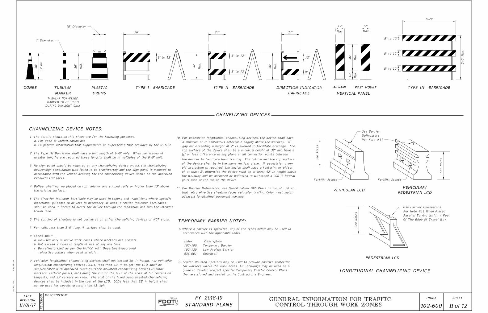
not be used for speeds greater than 45 mph.
devices shall be included in the cost of the LCD. LCDs less than 32" in height shall
tangents, and 25' centers on radii. The cost of the fixed supplemented channelizing
markers, vertical panels, etc.) along the run of the LCD, at the ends, at 50' centers on
supplemented with approved fixed (surface mounted) channelizing devices (tubular
longitudinal channelizing devices (LCDs) less than 32" in height, the LCD shall be
9. Vehicular longitudinal channelizing devices shall not exceed 36" in height. For vehicular
reflective collars when used at night.
c. Be reflectorized as per the MUTCD with Department-approved
b. Not exceed 2 miles in length of use at any one time.
a. Be used only in active work zones where workers are present.
8. Cones shall:
7. For rails less than 3'-0" long, 4" stripes shall be used.
6. The splicing of sheeting is not permitted on either channelizing devices or MOT signs.
travel lane.
shall be used in series to direct the driver through the transition and into the intended
directional guidance to drivers is necessary. If used, direction indicator barricades
5. The direction indicator barricade may be used in tapers and transitions where specific
the driving surface.
4. Ballast shall not be placed on top rails or any striped rails or higher than 13" above
Products List (APL).
accordance with the vendor drawing for the channelizing device shown on the Approved
device/sign combination was found to be crashworthy and the sign panel is mounted in
3. No sign panel should be mounted on any channelizing device unless the channelizing
greater lengths are required those lengths shall be in multiples of the 6'-0" unit.
2. The Type III Barricade shall have a unit length of 6'-0" only. When barricades of
b. To provide information that supplements or supersedes that provided by the MUTCD.
a. For ease of identification and
1. The details shown on this sheet are for the following purposes:
8" to 12"8" to 12"
8" to 12"
MARKER
TUBULARCONES
DRUMS
PLASTIC
5'-
0"
Min.
8" to 12"
8" to 12"
CHANELIZING DEVICES
that are signed and sealed by the Contractor's Engineer.
guide to develop project specific Temporary Traffic Control Plans
for workers within the work areas. APL drawings may be used as a
2. Trailer Mounted Barriers may be used to provide positive protection
Guardrail 536-001
Low Profile Barrier 102-120
Temporary Barrier 102-100
Index Description
accordance with the applicable Index:
1. Where a barrier is specified, any of the types below may be used in
8" to 12"
adjacent longitudinal pavement marking.
that retroreflective sheeting faces vehicular traffic. Color must match
11. For Barrier Delineators, see Specification 102. Place on top of unit so
point load at the top of the device.
the walkway and be anchored or ballasted to withstand a 200 lb lateral
of at least 2', otherwise the device must be at least 42" in height above
off protection is required, the device shall have a footprint or offset
of the device shall be in the same vertical plane. If pedestrian drop-
the devices to facilitate hand trailing. The bottom and the top surface
" or less difference in any plane at all connection points between 8
1
top surface of the device shall be a minimum height of 32" and have a
gap not exceeding a height of 2" is allowed to facilitate drainage. The
a minimum of 8" continuous detectable edging above the walkway. A
10. For pedestrian longitudinal channelizing devices, the device shall have

10/30/2017
9:3
6:4
9
AM
RE
VISIO
N DESCRIPTION:
REVISION
LAST
ofSTANDARD PLANS
FY 2018-19 SHEETINDEX GENERAL INFORMATION FOR TRAFFIC
CONTROL THROUGH WORK ZONES
12 12
102-60011/01/17
Pavement Marking
Centerline of
Travel Lanes
Lane Lines
Edge Lines
Edge Line
Travel Way
Edge of
Tangent
40' (Typ.) Through
Approach
Transition &
5' (Typ) Through
6" White
6" Double Yellow
RPMs (See Note 1 below)
USE OF RPMS TO SUPPLEMENT PAINT OR REMOVABLE TAPE IN WORK ZONES
PLACEMENT OF PAVEMENT MARKINGS
Transition Tangent Transition
Work Area
100'
Approach
100'
Approach
LW
6" 2"
LWLW
other widths are shown in the plans.
by the number of travel lanes unless
Total width of travel lanes divided LW =
PAVEMENT MARKINGS
NOTES FOR RAISED PAVEMENT MARKERS:
RPMs shall be placed at 5 feet center to center in approach and transition areas.
Placement of RPMs should be as shown in Index 706-001 with the following exceptions: 2.
Edge lines of gore areas. c.
Edge lines in transition & approach areas. b.
All lane lines.a.
RPMs shall be installed as a supplement to: 1.
equipment malfunction are to be placed at the Contractor's expense.
(Temporary), EA. RPMs used as a temporary substitute for paint or removable tape due to
RPMs used to supplement lane lines are to be paid for as Raised Pavement Marker 2.
supplement.
to the color of the marking for which they serve as a positioning guide, or for which they
The color of the raised pavement marker under both day and night conditions shall conform 1.