general information · edus391006-r2 60hz h/r 208/230v reyq72-336pbtj usa specification dec. 2010...
TRANSCRIPT

RXYQ-TYDN3 phase, 460V, 60Hz
RXYQ-TTJU3 phase, 208/230V, 60Hz
RXYQ-TYDN3 phase, 460V, 60Hz
RXYQ-TTJU3 phase, 208/230V, 60Hz
EDUS341411-M
General Information


EDUS341411-M
Table of Contents 1
General Information ............................................................................. EDUS341411-M(This booklet)
Indoor Units
Ceiling Mounted Cassette Type (Round Flow with Sensing).... ..........EDUS341400-F14
Ceiling Mounted Cassette Type (Round Flow) .......... ............EDUS391000-F1
4 Way Ceiling Mounted Cassette Type (2’×2’)........... ............EDUS391300-F9
Slim Ceiling Mounted Duct Type ......................... .............EDUS39-600-F2
Ceiling Mounted Duct Type................................ ............EDUS391400-F4
Ceiling Mounted Duct Type................................ ........ EDUS39-900A-F11
Ceiling Suspended Type ................................... .............EDUS39-600-F5
Wall Mounted Type .......................................... ............EDUS391100-F6
Floor Standing Type / Concealed Floor Standing Type .............. .............EDUS39-600-F7
Vertical Air Handling Unit................................... ..........EDUS391000-F12
Air Treatment Equipment
Outdoor Air Processing Unit............................... ........ EDUS39-900A-F10
Energy Recovery Ventilator ............................... ...........EDUS711116
Outdoor Units
Heat Pump ..................................................... 460V ..... EDUS341411-R1
208 / 230V..... EDUS341411-R2
Installation of Outdoor Units................................................................ EDUS341411-N
Controls .................................................................................................EDUS391000-C
Remote Controller
BRC1E72.........................................................................................EDUS721215
FXFQ-T
FXFQ-P
FXZQ-M
FXDQ-M
FXMQ-PA
FXMQ-M
FXHQ-M
FXAQ-P
FXLQ-M,FXNQ-M
FXTQ-PA
FXMQ-MF
VAM-G
RXYQ-T

Introduction EDUS341411-M
1. Introduction1.1 Publication List of Engineering Data for VRV Products
Refrigerant Type Product Series Book No. Hz, Type, Volts Model name Area Note Published in
R410A
Air cooled
Inverter P(B)
EDUS341411-M 60Hz H/P 460V60Hz H/P 208/230V
RXYQ72-408TYDNRXYQ72-408TTJU USA General
information Jan. 2015
EDUS341411-N 60Hz H/P 460V60Hz H/P 208/230V
RXYQ72-408TYDNRXYQ72-408TTJU USA Installation Dec. 2014
EDUS341411-R1 60Hz H/P 460V RXYQ72-408TYDN USA Specification Nov. 2014EDUS341411-R2 60Hz H/P 208/230V RXYQ72-408TTJU USA Specification Nov. 2014
EDUS391004-M
60Hz H/P 460V60Hz H/P 208/230V60Hz H/R 460V60Hz H/R 208/230V
RXYQ72-360PBYDRXYQ72-360PBTJREYQ72-336PBYDREYQ72-336PBTJ
USA General information Jan. 2011
EDUS391004-N
60Hz H/P 460V60Hz H/P 208/230V60Hz H/R 460V60Hz H/R 208/230V
RXYQ72-360PBYDRXYQ72-360PBTJREYQ72-336PBYDREYQ72-336PBTJ
USA Installation Dec. 2010
EDUS391005-R1 60Hz H/P 460V RXYQ72-360PBYD USA Specification Dec. 2010EDUS391005-R2 60Hz H/R 460V REYQ72-336PBYD USA Specification Dec. 2010EDUS391006-R1 60Hz H/P 208/230V RXYQ72-360PBTJ USA Specification Dec. 2010EDUS391006-R2 60Hz H/R 208/230V REYQ72-336PBTJ USA Specification Dec. 2010
EDUS34-900-R1 60Hz H/P 208/230V RXYMQ36/48PVJU USA Specification Feb. 2010
Water cooled
EDUS301214-M
60Hz H/P 208/230V60Hz H/R 208/230V60Hz H/P 460V60Hz H/R 460V
RWEYQ72-252PTJURWEYQ72-252PYDN USA General
information Dec. 2012
EDUS301214-N
60Hz H/P 208/230V60Hz H/R 208/230V60Hz H/P 460V60Hz H/R 460V
RWEYQ72-252PTJURWEYQ72-252PYDN USA Installation Dec. 2012
EDUS301214-R
60Hz H/P 208/230V60Hz H/R 208/230V60Hz H/P 460V60Hz H/R 460V
RWEYQ72-252PTJURWEYQ72-252PYDN USA Specification Dec. 2012
VRV Indoor units
EDUS391400-F14 60Hz FXFQ07-48TVJU USA
Ceiling Mounted Cassette (Round Flow with Sensing) Type
Nov. 2014
EDUS391000-F1 60Hz FXFQ09-48PVJU USACeiling Mounted Cassette (Round Flow) Type
Nov. 2010
EDUS391300-F9 60Hz FXZQ07-18MVJU9 USA4 Way Ceiling Mounted Cassette (2' × 2') Type
Oct. 2013
EDUS39-600-F2 60Hz FXDQ07-24MVJU USASlim Ceiling Mounted Duct Type
Sep. 2006
EDUS391400-F4 60Hz FXMQ07-54PAVJU USA
Ceiling Mounted Duct Type(Middle and High Static Pressure)
Oct. 2014
EDUS39-900A-F11 60Hz FXMQ72/96MVJU USA Ceiling Mounted Duct Type May 2010
EDUS39-600-F5 60Hz FXHQ12-36MVJU USA Ceiling Suspended Type Sep. 2006
EDUS391100-F6 60Hz FXAQ07-24PVJU USA Wall Mounted Type Jan. 2012
EDUS39-600-F7 60Hz FXLQ12-24MVJUFXNQ12-24MVJU USA
Floor Standing TypeConcealed Floor Standing Type
Sep. 2006
EDUS391000-F12 60Hz FXTQ12-54PAVJU USA Vertical Air Handling Unit Sep. 2010
EDUS39-900A-F10 60Hz FXMQ48-96MFVJU USA Outdoor Air Processing Unit May 2010
EDUS39-900-F8 60Hz H/R 208/230V BSVQ36-96PVJU USA Branch Selector Nov. 2009
EDUS391100-F13 60Hz H/R 208/230V BSV4/6Q36PVJU USA Centralized Branch Selector Mar. 2011
2 Introduction

EDUS341411-M Introduction
This time we publish EDUS341411-M, N, R1, R2 as shown by .C/O: Cooling onlyH/P: Heat pumpH/R: Heat recovery
R410A
ControlsEDUS391000-C —
BRC1E71, BRC4C/7C/7E, BRC2A71DCS302C71, DCS301C71,DST301BA61, DCS601C71KRP1C74/75
USA
Remote controller
Control devices
Adaptor
Aug. 2010
EDUS721215 — BRC1E72 USA Navigation remote controller Nov. 2012
Networks
EDUS721212 — DCM601A71DCM601A72 USA intelligent Touch
Manager Oct. 2012
EDUS72-746 — DAM602A71DAM602A72 USA intelligent
Manager III Dec. 2007
EDUS72-608 — DCS601C71 USA intelligent Touch Controller Dec. 2006
EDUS72-749 — DMS502B71 USA Interface for use in BACnet Oct. 2007
Option for all type OHUS07-1 — For indoor and outdoor units USA Option handbook Nov. 2007
Energy Recovery Ventilator (VAM) EDUS711116 60 HZ VAM300-1200GVJU USA Energy Recovery Ventilator Jul. 2011
Refrigerant Type Product Series Book No. Hz, Type, Volts Model name Area Note Published in
Introduction 3

Introduction EDUS341411-M
4 Introduction

EDUS341411-M
General Information 5
General Information1. Model Names of Indoor/Outdoor Units........................................................6
1.1 Indoor Units .................................................................................................. 61.2 Outdoor Units ............................................................................................... 61.3 Air Treatment Equipment ............................................................................. 7
2. External Appearance...................................................................................82.1 Indoor Units .................................................................................................. 82.2 Air Treatment Equipment ............................................................................. 82.3 Outdoor Units ............................................................................................... 9
3. Combination of Outdoor Units...................................................................104. Nomenclature............................................................................................115. Capacity Range.........................................................................................13
5.1 Combination Ratio...................................................................................... 13
6. Control Systems........................................................................................156.1 Individual Control Systems......................................................................... 156.2 DAIKIN Building Air Conditioning Control System (D-BACS)..................... 196.3 Various Control by Liquid Crystal Remote Controller................................. 206.4 Building Control System Introduction ......................................................... 266.5 Specifications of the Control Wiring ........................................................... 296.6 Wiring Example .......................................................................................... 306.7 Length of Transmission Wiring................................................................... 326.8 Connection Method .................................................................................... 336.9 Unit and Group ........................................................................................... 376.10 Number of Connectable Units .................................................................... 386.11 Group and Zone ......................................................................................... 38
7. Guide Specifications .................................................................................417.1 Guide Specifications................................................................................... 41
8. Caution for Refrigerant Leaks ...................................................................438.1 Introduction................................................................................................. 438.2 Procedure for Checking Maximum Concentration...................................... 44
9. Safety Devices Setting ..............................................................................46
Model Names of Indoor/Outdoor Units EDUS341411-M
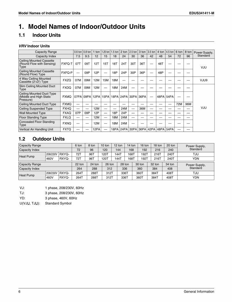
1. Model Names of Indoor/Outdoor Units1.1 Indoor Units
VRV Indoor Units
1.2 Outdoor Units
Capacity Range 0.6 ton 0.8 ton 1 ton 1.25 ton 1.5 ton 2 ton 2.5 ton 3 ton 3.5 ton 4 ton 4.5 ton 6 ton 8 ton Power Supply, StandardCapacity Index 7.5 9.5 12 15 18 24 30 36 42 48 54 72 96
Ceiling Mounted Cassette (Round Flow with Sensing) Type
FXFQ-T 07T 09T 12T 15T 18T 24T 30T 36T — 48T — — —VJU
Ceiling Mounted Cassette (Round Flow) Type FXFQ-P — 09P 12P — 18P 24P 30P 36P — 48P — — —
4 Way Ceiling Mounted Cassette (2'×2') Type FXZQ 07M 09M 12M 15M 18M — — — — — — — — VJU9
Slim Ceiling Mounted Duct Type FXDQ 07M 09M 12M — 18M 24M — — — — — — —
VJU
Ceiling Mounted Duct Type (Middle and High Static Pressure)
FXMQ 07PA 09PA 12PA 15PA 18PA 24PA 30PA 36PA — 48PA 54PA — —
Ceiling Mounted Duct Type FXMQ — — — — — — — — — — — 72M 96M
Ceiling Suspended Type FXHQ — — 12M — — 24M — 36M — — — — —Wall Mounted Type FXAQ 07P 09P 12P — 18P 24P — — — — — — —
Floor Standing Type FXLQ — — 12M — 18M 24M — — — — — — —
Concealed Floor Standing Type FXNQ — — 12M — 18M 24M — — — — — — —
Vertical Air Handling Unit FXTQ — — 12PA — 18PA 24PA 30PA 36PA 42PA 48PA 54PA — —
Capacity Range 6 ton 8 ton 10 ton 12 ton 14 ton 16 ton 18 ton 20 ton Power Supply, StandardCapacity Index 72 96 120 144 168 192 216 240
Heat Pump208/230V RXYQ- 72T 96T 120T 144T 168T 192T 216T 240T TJU
460V RXYQ- 72T 96T 120T 144T 168T 192T 216T 240T YDN
Capacity Range 22 ton 24 ton 26 ton 28 ton 30 ton 32 ton 34 ton Power Supply, StandardCapacity Index 264 288 312 336 360 384 408
Heat Pump208/230V RXYQ- 264T 288T 312T 336T 360T 384T 408T TJU
460V RXYQ- 264T 288T 312T 336T 360T 384T 408T YDN
VJ: 1 phase, 208/230V, 60Hz
TJ: 3 phase, 208/230V, 60Hz
YD: 3 phase, 460V, 60Hz
U(VJU, TJU): Standard Symbol
6 General Information
EDUS341411-M Model Names of Indoor/Outdoor Units
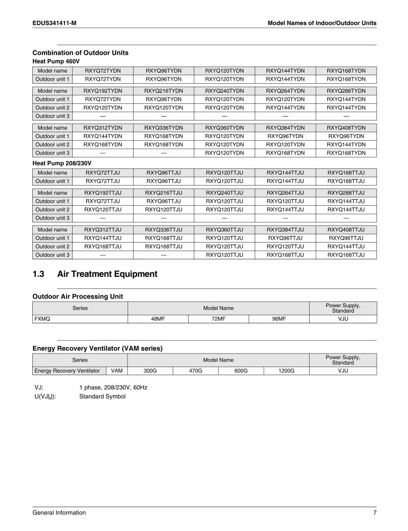
Combination of Outdoor UnitsHeat Pump 460V
Heat Pump 208/230V
1.3 Air Treatment Equipment
Outdoor Air Processing Unit
Energy Recovery Ventilator (VAM series)
Model name RXYQ72TYDN RXYQ96TYDN RXYQ120TYDN RXYQ144TYDN RXYQ168TYDN
Outdoor unit 1 RXYQ72TYDN RXYQ96TYDN RXYQ120TYDN RXYQ144TYDN RXYQ168TYDN
Model name RXYQ192TYDN RXYQ216TYDN RXYQ240TYDN RXYQ264TYDN RXYQ288TYDN
Outdoor unit 1 RXYQ72TYDN RXYQ96TYDN RXYQ120TYDN RXYQ120TYDN RXYQ144TYDN
Outdoor unit 2 RXYQ120TYDN RXYQ120TYDN RXYQ120TYDN RXYQ144TYDN RXYQ144TYDN
Outdoor unit 3 — — — — —
Model name RXYQ312TYDN RXYQ336TYDN RXYQ360TYDN RXYQ384TYDN RXYQ408TYDN
Outdoor unit 1 RXYQ144TYDN RXYQ168TYDN RXYQ120TYDN RXYQ96TYDN RXYQ96TYDN
Outdoor unit 2 RXYQ168TYDN RXYQ168TYDN RXYQ120TYDN RXYQ120TYDN RXYQ144TYDN
Outdoor unit 3 — — RXYQ120TYDN RXYQ168TYDN RXYQ168TYDN
Model name RXYQ72TTJU RXYQ96TTJU RXYQ120TTJU RXYQ144TTJU RXYQ168TTJU
Outdoor unit 1 RXYQ72TTJU RXYQ96TTJU RXYQ120TTJU RXYQ144TTJU RXYQ168TTJU
Model name RXYQ192TTJU RXYQ216TTJU RXYQ240TTJU RXYQ264TTJU RXYQ288TTJU
Outdoor unit 1 RXYQ72TTJU RXYQ96TTJU RXYQ120TTJU RXYQ120TTJU RXYQ144TTJU
Outdoor unit 2 RXYQ120TTJU RXYQ120TTJU RXYQ120TTJU RXYQ144TTJU RXYQ144TTJU
Outdoor unit 3 — — — — —
Model name RXYQ312TTJU RXYQ336TTJU RXYQ360TTJU RXYQ384TTJU RXYQ408TTJU
Outdoor unit 1 RXYQ144TTJU RXYQ168TTJU RXYQ120TTJU RXYQ96TTJU RXYQ96TTJU
Outdoor unit 2 RXYQ168TTJU RXYQ168TTJU RXYQ120TTJU RXYQ120TTJU RXYQ144TTJU
Outdoor unit 3 — — RXYQ120TTJU RXYQ168TTJU RXYQ168TTJU
Series Model Name Power Supply, Standard
FXMQ 48MF 72MF 96MF VJU
Series Model Name Power Supply, Standard
Energy Recovery Ventilator VAM 300G 470G 600G 1200G VJU
VJ: 1 phase, 208/230V, 60Hz
U(VJU): Standard Symbol
General Information 7
External Appearance EDUS341411-M
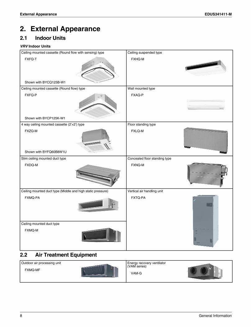
2. External Appearance2.1 Indoor UnitsVRV Indoor Units
2.2 Air Treatment Equipment
Ceiling mounted cassette (Round flow with sensing) type
FXFQ-T
Shown with BYCQ125B-W1
Ceiling suspended type
FXHQ-M
Ceiling mounted cassette (Round flow) type
FXFQ-P
Shown with BYCP125K-W1
Wall mounted type
FXAQ-P
4 way ceiling mounted cassette (2’×2’) type
FXZQ-M
Shown with BYFQ60B8W1U
Floor standing type
FXLQ-M
Slim ceiling mounted duct type
FXDQ-M
Concealed floor standing type
FXNQ-M
Ceiling mounted duct type (Middle and high static pressure)
FXMQ-PA
Vertical air handling unit
FXTQ-PA
Ceiling mounted duct type
FXMQ-M
Outdoor air processing unit
FXMQ-MF
Energy recovery ventilator (VAM series)
VAM-G
8 General Information

EDUS341411-M External Appearance
2.3 Outdoor UnitsSingle Outdoor Units
Double Outdoor Units
Triple Outdoor Units
RXYQ96 / 120 / 144 / 168TRXYQ72T
RXYQ192T RXYQ216 / 240 / 264 / 288 / 312 / 336T
RXYQ360 / 384 / 408T
General Information 9

Combination of Outdoor Units EDUS341411-M
3. Combination of Outdoor Units
Note: 1 For multiple connection, the outdoor unit multi connection piping kit (separately sold) is required.
System capacity Number of units
Module Outdoor Unit Multi Connection Piping Kit 1Ton HP kW 72 96 120 144 168
16 20 56.3 2
BHFP26P100U
18 22.5 63.3 2
20 25 70.3 2
22 27.5 77.4 2
24 30 84.4 2
26 32.5 91.4 2
28 35 98.5 2
30 37.5 105.5 3
BHFP26P151U32 40 112.5 3
34 42.5 119.6 3
10 General Information

EDUS341411-M Nomenclature
4. Nomenclature
VRV Indoor Unit
BP Unit
M 54 VJPA UX QF
Standard SymbolU: United States of America
Power Supply SymbolVJ: 1 phase, 208/230V, 60Hz
Indicates Major Design Category
Capacity Indication in Cooling07: 7,500 Btu/h 18: 18,000 Btu/h 42: 42,000 Btu/h 96: 96,000 Btu/h09: 9,500 Btu/h 24: 24,000 Btu/h 48: 48,000 Btu/h12: 12,000 Btu/h 30: 30,000 Btu/h 54: 54,000 Btu/h15: 15,000 Btu/h 36: 36,000 Btu/h 72: 72,000 Btu/h
Refrigerant and TypeQ: R410A, Heat Pump, Heat Recovery
ShapeF: Ceiling Mounted Cassette (Round Flow with Sensing/Round Flow)Z: 4 Way Ceiling Mounted Cassette (2'×2')D: Slim Ceiling Mounted DuctM: Ceiling Mounted DuctH: Ceiling SuspendedA: Wall MountedL: Floor StandingN: Concealed Floor StandingT: Vertical Air Handling Unit
Series CategoryX: Inverter
Unit CategoryF: Indoor Unit for Air Cooled Type
BPMK 048 2A US
Standard SymbolU: United States of America
Number of Port
Indicates Major Design Category
Series Category
RefrigerantS: R410A
Unit CategoryBPMK: Multi-room unit
General Information 11

Nomenclature EDUS341411-M
Outdoor Unit
Air Treatment EquipmentEnergy Recovery Ventilator (VAM series)
TJU408QR X Y T
Power Supply SymbolTJU: 3 phase, 208/230V, 60HzYDN: 3 phase, 460V, 60Hz
Indicates Major Design Category
RefrigerantQ: R410A
TypeY: Heat pumpBlank: Cooling only
Series categoryX: Inverter
Unit categoryR: Outdoor unit for air cooled type
Capacity Indication in cooling 72: 72,000 Btu/h 96: 96,000 Btu/h
144: 144,000 Btu/h168: 168,000 Btu/h
192: 192,000 Btu/h216: 216,000 Btu/h240: 240,000 Btu/h
312: 312,000 Btu/h336: 336,000 Btu/h360: 360,000 Btu/h
264: 264,000 Btu/h288: 288,000 Btu/h
384: 384,000 Btu/h408: 408,000 Btu/h
120: 120,000 Btu/h
UG300V A M VJ
Standard SymbolU: United States of America
Power Supply SymbolVJ: 1 phase, 208/230V, 60Hz
Indicates Major Design Category
Airflow rate (H)300: 300cfm 600: 600cfm470: 470cfm 1200: 1,200cfm
Mounted type
Air
Ventilation
12 General Information
EDUS341411-M Capacity Range
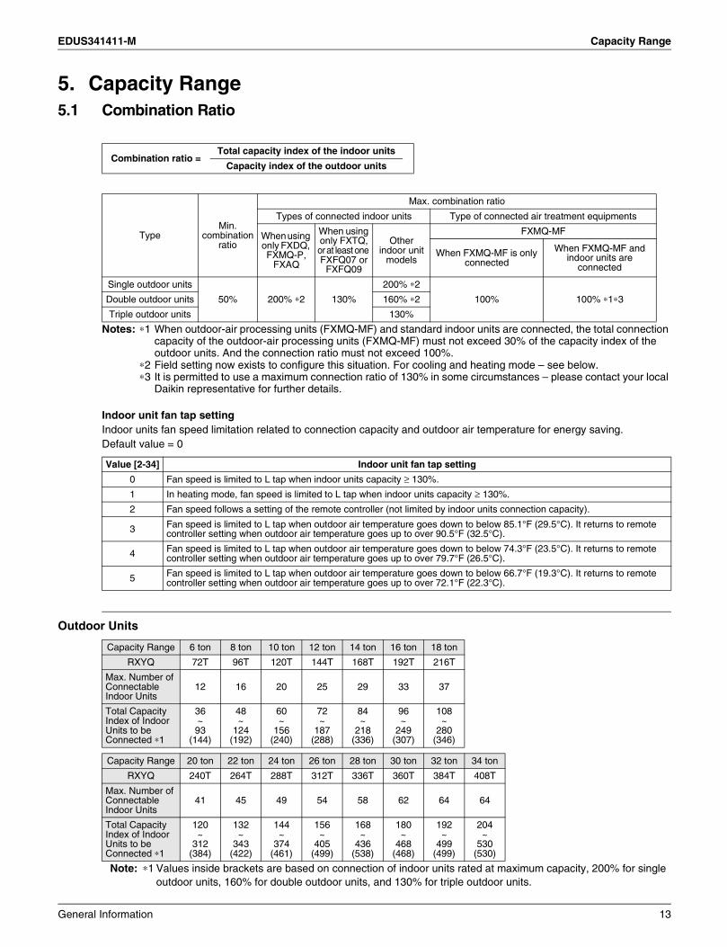
5. Capacity Range5.1 Combination Ratio
Notes: ∗1 When outdoor-air processing units (FXMQ-MF) and standard indoor units are connected, the total connection capacity of the outdoor-air processing units (FXMQ-MF) must not exceed 30% of the capacity index of the outdoor units. And the connection ratio must not exceed 100%.
∗2 Field setting now exists to configure this situation. For cooling and heating mode – see below.∗3 It is permitted to use a maximum connection ratio of 130% in some circumstances – please contact your local
Daikin representative for further details.
Indoor unit fan tap settingIndoor units fan speed limitation related to connection capacity and outdoor air temperature for energy saving.Default value = 0
Outdoor Units
Note: ∗1 Values inside brackets are based on connection of indoor units rated at maximum capacity, 200% for single outdoor units, 160% for double outdoor units, and 130% for triple outdoor units.
Combination ratio =Total capacity index of the indoor units
Capacity index of the outdoor units
TypeMin.
combination ratio
Max. combination ratio
Types of connected indoor units Type of connected air treatment equipments
When using only FXDQ, FXMQ-P,
FXAQ
When using only FXTQ, or at least one FXFQ07 or
FXFQ09
Other indoor unit
models
FXMQ-MF
When FXMQ-MF is only connected
When FXMQ-MF and indoor units are
connected
Single outdoor units
50% 200% ∗2 130%
200% ∗2
100% 100% ∗1∗3Double outdoor units 160% ∗2
Triple outdoor units 130%
Value [2-34] Indoor unit fan tap setting
0 Fan speed is limited to L tap when indoor units capacity ≥ 130%.
1 In heating mode, fan speed is limited to L tap when indoor units capacity ≥ 130%.
2 Fan speed follows a setting of the remote controller (not limited by indoor units connection capacity).
3 Fan speed is limited to L tap when outdoor air temperature goes down to below 85.1°F (29.5°C). It returns to remote controller setting when outdoor air temperature goes up to over 90.5°F (32.5°C).
4 Fan speed is limited to L tap when outdoor air temperature goes down to below 74.3°F (23.5°C). It returns to remote controller setting when outdoor air temperature goes up to over 79.7°F (26.5°C).
5 Fan speed is limited to L tap when outdoor air temperature goes down to below 66.7°F (19.3°C). It returns to remote controller setting when outdoor air temperature goes up to over 72.1°F (22.3°C).
Capacity Range 6 ton 8 ton 10 ton 12 ton 14 ton 16 ton 18 ton
RXYQ 72T 96T 120T 144T 168T 192T 216T
Max. Number of Connectable Indoor Units
12 16 20 25 29 33 37
Total Capacity Index of Indoor Units to be Connected ∗1
36~93
(144)
48~
124(192)
60~
156(240)
72~
187(288)
84~
218(336)
96~
249(307)
108~
280(346)
Capacity Range 20 ton 22 ton 24 ton 26 ton 28 ton 30 ton 32 ton 34 ton
RXYQ 240T 264T 288T 312T 336T 360T 384T 408T
Max. Number of Connectable Indoor Units
41 45 49 54 58 62 64 64
Total Capacity Index of Indoor Units to be Connected ∗1
120~
312(384)
132~
343(422)
144~
374(461)
156~
405(499)
168~
436(538)
180~
468(468)
192~
499(499)
204~
530(530)
General Information 13
Capacity Range EDUS341411-M
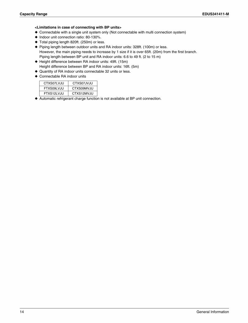
<Limitations in case of connecting with BP units>Connectable with a single unit system only (Not connectable with multi connection system)Indoor unit connection ratio: 80-130%.Total piping length 820ft. (250m) or less.Piping length between outdoor units and RA indoor units: 328ft. (100m) or less.However, the main piping needs to increase by 1 size if it is over 65ft. (20m) from the first branch.Piping length between BP unit and RA indoor units: 6.6 to 49 ft. (2 to 15 m)Height difference between RA indoor units: 49ft. (15m)Height difference between BP and RA indoor units: 16ft. (5m)Quantity of RA indoor units connectable 32 units or less.Connectable RA indoor units
Automatic refrigerant charge function is not available at BP unit connection.
CTXS07LVJU CTXS07JVJU
FTXS09LVJU CTXS09MVJU
FTXS12LVJU CTXS12MVJU
14 General Information
EDUS341411-M Control Systems
6. Control Systems6.1 Individual Control Systems
Outdoor unit
Indoor unit
Forced OFF input
Remote controllerRemote controller Remote controller
Remote controllerRemote controller
Remote controller
Remote controller
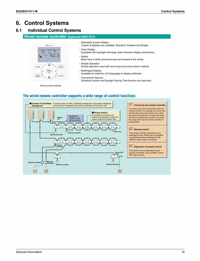
The indoor unit can be connected by the two remote controller, for example one in the room and the other one in the control room, which can control the operation of indoor unit freely.(The last command has a priority.) Of course, the group control by two remote controller is also possible.
Control by two remote controller
The system can be expanded to add several controllers, such as BMS, Forced OFF input and etc.
Expansion of system control
In all the series of VRV, Cool/Heat changeover in the same refrigerant circuit can be changed by the remote controller of the indoor unit.
Control of Cool/Heat changeover
One remote controller can control the operation of max.16 indoor units at the same time.
Group control
Equipment related to the central control
1 2
The wiring of remote controller can be extended to max.1640ft and it is possible to install the remote controllers for the different indoor units in one place.
Remote control
3
3
2
1
Wired remote controller (Optional) BRC1E72
Wired remote controller
– Selectable Screen Display3 types of displays are available; Standard, Detailed and Simple.
– Clear DisplayEquipped with backlight and large sized character display and buttons.
– StylishBasic tone is white and arrow keys are located at the center.
– Simple OperationSimple operation used with arrow keys and menu-driven method.
– Multilingual DisplayAvailable for selection of 3 languages to display arbitrarily.
– Convenient FeaturesSchedule function and Daylight Saving Time function are improved.
General Information 15
Control Systems EDUS341411-M
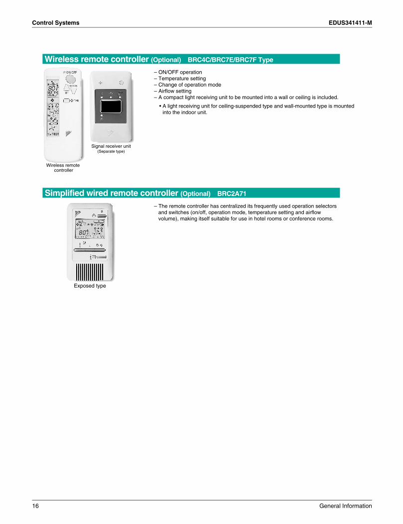
– The remote controller has centralized its frequently used operation selectors and switches (on/off, operation mode, temperature setting and airflow volume), making itself suitable for use in hotel rooms or conference rooms.
Exposed type
Simplified wired remote controller (Optional) BRC2A71
– ON/OFF operation– Temperature setting– Change of operation mode– Airflow setting– A compact light receiving unit to be mounted into a wall or ceiling is included.
• A light receiving unit for ceiling-suspended type and wall-mounted type is mounted into the indoor unit.
Signal receiver unit(Separate type)
Wireless remote controller
Wireless remote controller (Optional) BRC4C/BRC7E/BRC7F Type
16 General Information
EDUS341411-M Control Systems
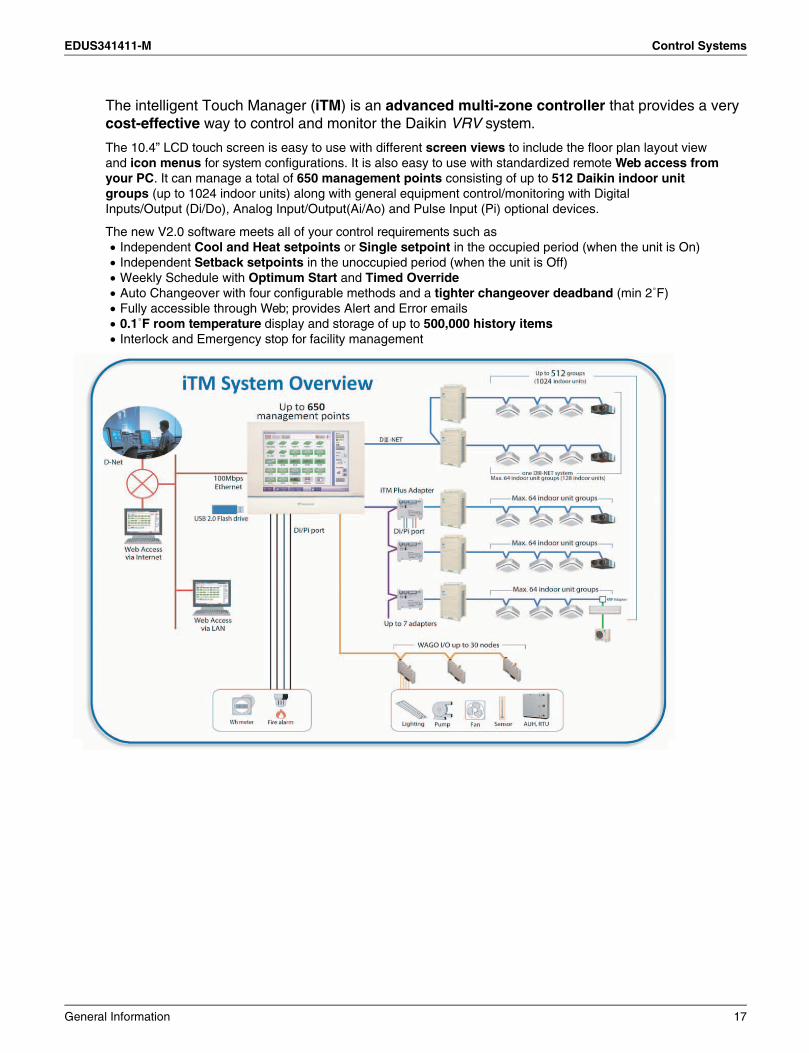
The intelligent Touch Manager (iTM) is an advanced multi-zone controller that provides a verycost-effective way to control and monitor the Daikin VRV system.
The 10.4” LCD touch screen is easy to use with different screen views to include the floor plan layout view and icon menus for system configurations. It is also easy to use with standardized remote Web access from your PC. It can manage a total of 650 management points consisting of up to 512 Daikin indoor unit groups (up to 1024 indoor units) along with general equipment control/monitoring with Digital Inputs/Output (Di/Do), Analog Input/Output(Ai/Ao) and Pulse Input (Pi) optional devices.
The new V2.0 software meets all of your control requirements such as• Independent Cool and Heat setpoints or Single setpoint in the occupied period (when the unit is On)• Independent Setback setpoints in the unoccupied period (when the unit is Off) • Weekly Schedule with Optimum Start and Timed Override• Auto Changeover with four configurable methods and a tighter changeover deadband (min 2˚F) • Fully accessible through Web; provides Alert and Error emails• 0.1˚F room temperature display and storage of up to 500,000 history items• Interlock and Emergency stop for facility management
General Information 17
Control Systems EDUS341411-M
(Interface for use in LONWORKS )
(Interface for use in BACnet )DMS502B71
DMS504C71
Ethernet
Local Controller
Please contact Daikin for compatibility with BMS system
SecurityPower supply facility
Fire alarm
Elevator Pump Lighting
...etc
BMS
VRV System
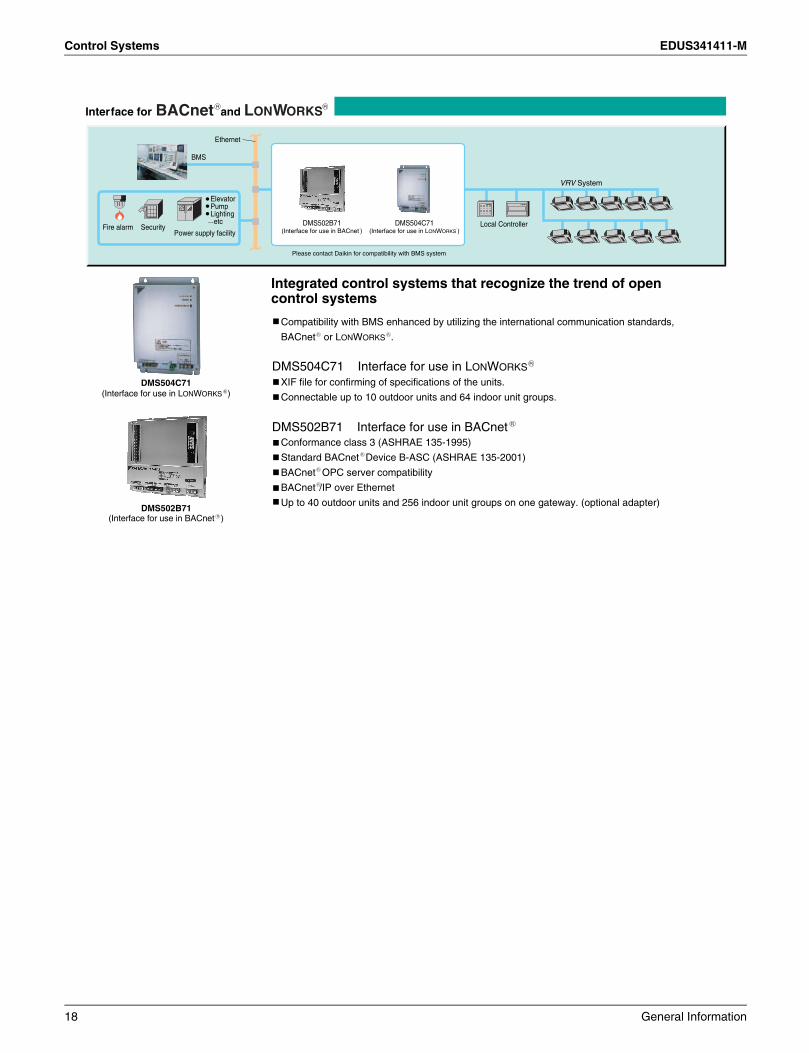
BACnet LONWORKSInterface for and
DMS502B71(Interface for use in BACnet¨)
DMS504C71(Interface for use in LONWORKS
¨)
Compatibility with BMS enhanced by utilizing the international communication standards,
BACnet or LONWORKS .
XIF file for confirming of specifications of the units.
Connectable up to 10 outdoor units and 64 indoor unit groups.
Conformance class 3 (ASHRAE 135-1995)
Standard BACnet Device B-ASC (ASHRAE 135-2001)
BACnet OPC server compatibility
BACnet /IP over Ethernet
Up to 40 outdoor units and 256 indoor unit groups on one gateway. (optional adapter)
DMS504C71 Interface for use in LONWORKS
DMS502B71 Interface for use in BACnet
Integrated control systems that recognize the trend of open control systems
18 General Information
EDUS341411-M Control Systems
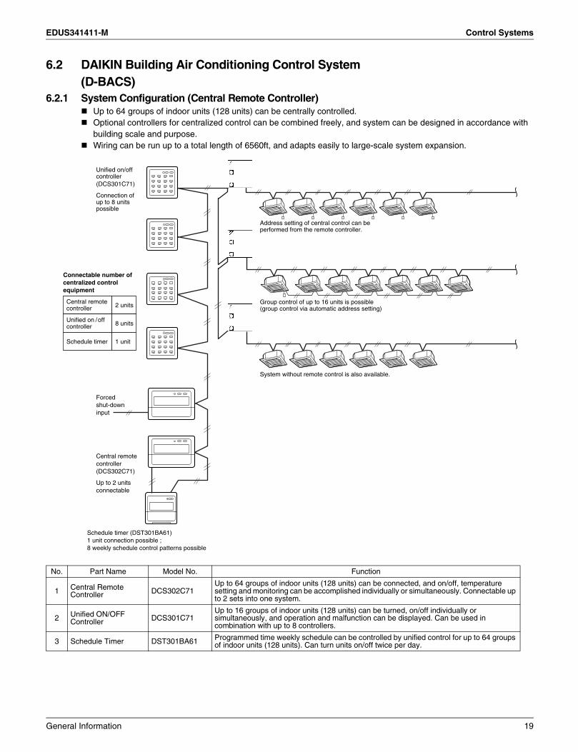
6.2 DAIKIN Building Air Conditioning Control System(D-BACS)
6.2.1 System Configuration (Central Remote Controller)Up to 64 groups of indoor units (128 units) can be centrally controlled.Optional controllers for centralized control can be combined freely, and system can be designed in accordance with building scale and purpose.Wiring can be run up to a total length of 6560ft, and adapts easily to large-scale system expansion.
No. Part Name Model No. Function
1 Central Remote Controller DCS302C71
Up to 64 groups of indoor units (128 units) can be connected, and on/off, temperature setting and monitoring can be accomplished individually or simultaneously. Connectable up to 2 sets into one system.
2 Unified ON/OFF Controller DCS301C71
Up to 16 groups of indoor units (128 units) can be turned, on/off individually or simultaneously, and operation and malfunction can be displayed. Can be used in combination with up to 8 controllers.
3 Schedule Timer DST301BA61 Programmed time weekly schedule can be controlled by unified control for up to 64 groups of indoor units (128 units). Can turn units on/off twice per day.
Central remote controller(DCS302C71)
Up to 2 units connectable
Unified on/off controller(DCS301C71)
Connection of up to 8 unitspossible
Schedule timer (DST301BA61)1 unit connection possible ; 8 weekly schedule control patterns possible
Forced shut-down input
Address setting of central control can be performed from the remote controller.
Group control of up to 16 units is possible (group control via automatic address setting)
System without remote control is also available.
Connectable number of centralized control equipment
Central remotecontroller 2 units
Unified on /offcontroller 8 units
Schedule timer 1 unit
General Information 19
Control Systems EDUS341411-M
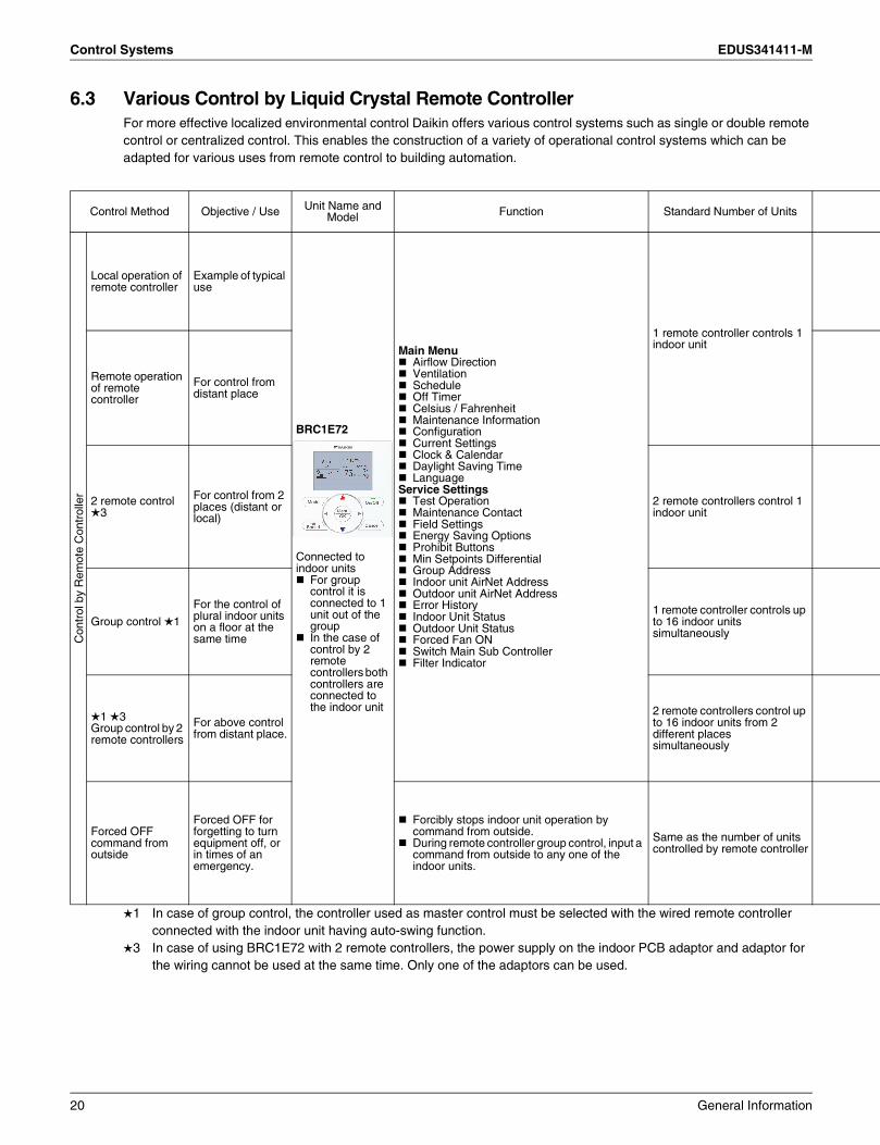
6.3 Various Control by Liquid Crystal Remote ControllerFor more effective localized environmental control Daikin offers various control systems such as single or double remote control or centralized control. This enables the construction of a variety of operational control systems which can be adapted for various uses from remote control to building automation.
1 In case of group control, the controller used as master control must be selected with the wired remote controller connected with the indoor unit having auto-swing function.
3 In case of using BRC1E72 with 2 remote controllers, the power supply on the indoor PCB adaptor and adaptor for the wiring cannot be used at the same time. Only one of the adaptors can be used.
Control Method Objective / Use Unit Name and Model Function Standard Number of Units
Con
trol
by
Rem
ote
Con
trol
ler
Local operation of remote controller
Example of typical use
BRC1E72
Connected to indoor units
For group control it is connected to 1 unit out of the groupIn the case of control by 2 remote controllers both controllers are connected to the indoor unit
Main MenuAirflow DirectionVentilationScheduleOff TimerCelsius / FahrenheitMaintenance InformationConfigurationCurrent SettingsClock & CalendarDaylight Saving TimeLanguage
Service SettingsTest OperationMaintenance ContactField SettingsEnergy Saving OptionsProhibit ButtonsMin Setpoints DifferentialGroup AddressIndoor unit AirNet AddressOutdoor unit AirNet AddressError HistoryIndoor Unit StatusOutdoor Unit StatusForced Fan ONSwitch Main Sub ControllerFilter Indicator
1 remote controller controls 1 indoor unit
Remote operation of remote controller
For control from distant place
2 remote control 3
For control from 2 places (distant or local)
2 remote controllers control 1 indoor unit
Group control 1
For the control of plural indoor units on a floor at the same time
1 remote controller controls up to 16 indoor units simultaneously
1 3Group control by 2 remote controllers
For above control from distant place.
2 remote controllers control up to 16 indoor units from 2 different places simultaneously
Forced OFF command from outside
Forced OFF for forgetting to turn equipment off, or in times of an emergency.
Forcibly stops indoor unit operation by command from outside.During remote controller group control, input a command from outside to any one of the indoor units.
Same as the number of units controlled by remote controller
20 General Information
EDUS341411-M Control Systems
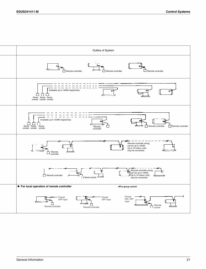
Outline of System
For local operation of remote controller For group control
Remote controller Remote controller Remote controller
Remotecontroller
Remotecontroller
Remotecontroller
Available up to 1640ft respectively
Remotecontroller
Remotecontroller
Remotecontroller
Remotecontroller
Remote controller Remote controller
Available up to 1640ft respectively
Remotecontroller
Remote controller wiring can be up to 1640ft.Up to 16 indoor units may be connected.
Remote controllerRemote controller
Remote controller wiring can be up to 1640ft.Up to 16 indoor unitsmay be connected.
Remote controller Remote controllerRemote control
Forced OFF input
Forced OFF input
ForcedON / OFF input
General Information 21
Control Systems EDUS341411-M
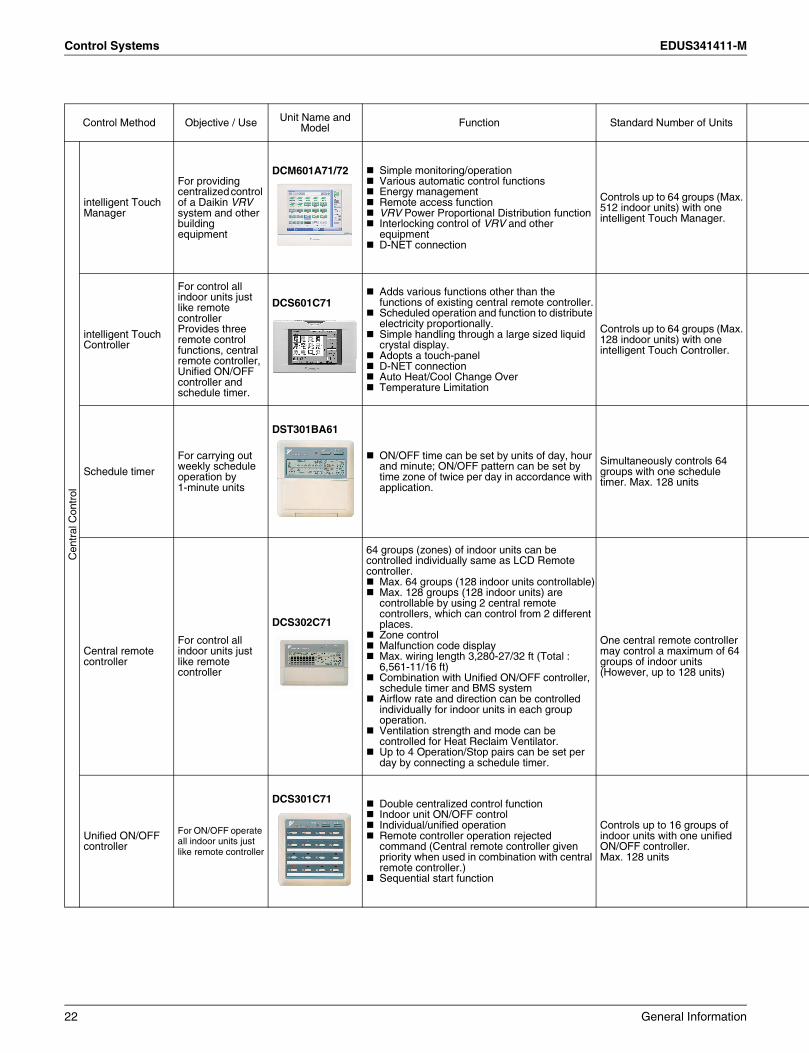
Control Method Objective / Use Unit Name and Model Function Standard Number of Units
Cen
tral
Con
trol
intelligent Touch Manager
For providing centralized control of a Daikin VRV system and other building equipment
DCM601A71/72 Simple monitoring/operationVarious automatic control functionsEnergy managementRemote access functionVRV Power Proportional Distribution functionInterlocking control of VRV and other equipmentD-NET connection
Controls up to 64 groups (Max. 512 indoor units) with one intelligent Touch Manager.
intelligent Touch Controller
For control all indoor units just like remote controllerProvides three remote control functions, central remote controller, Unified ON/OFF controller and schedule timer.
DCS601C71Adds various functions other than the functions of existing central remote controller.Scheduled operation and function to distribute electricity proportionally.Simple handling through a large sized liquid crystal display.Adopts a touch-panelD-NET connectionAuto Heat/Cool Change OverTemperature Limitation
Controls up to 64 groups (Max. 128 indoor units) with one intelligent Touch Controller.
Schedule timer
For carrying out weekly schedule operation by1-minute units
DST301BA61
ON/OFF time can be set by units of day, hour and minute; ON/OFF pattern can be set by time zone of twice per day in accordance with application.
Simultaneously controls 64 groups with one schedule timer. Max. 128 units
Central remote controller
For control all indoor units just like remote controller
DCS302C71
64 groups (zones) of indoor units can be controlled individually same as LCD Remote controller.
Max. 64 groups (128 indoor units controllable)Max. 128 groups (128 indoor units) are controllable by using 2 central remote controllers, which can control from 2 different places. Zone control Malfunction code displayMax. wiring length 3,280-27/32 ft (Total : 6,561-11/16 ft)Combination with Unified ON/OFF controller, schedule timer and BMS system Airflow rate and direction can be controlled individually for indoor units in each group operation. Ventilation strength and mode can be controlled for Heat Reclaim Ventilator. Up to 4 Operation/Stop pairs can be set per day by connecting a schedule timer.
One central remote controller may control a maximum of 64 groups of indoor units (However, up to 128 units)
Unified ON/OFF controller
For ON/OFF operate all indoor units just like remote controller
DCS301C71 Double centralized control functionIndoor unit ON/OFF controlIndividual/unified operationRemote controller operation rejected command (Central remote controller given priority when used in combination with central remote controller.)Sequential start function
Controls up to 16 groups of indoor units with one unified ON/OFF controller.Max. 128 units
22 General Information

EDUS341411-M Control Systems
Outline of System
When using one of unit of intelligent Touch Manager
When using one of unit of intelligent touch controller
When using one unit of schedule timer
Note: For the schedule timer, take the electric power supply from the indoor unit.When using one unit of central remote controller
When using one unit of unified ON/OFF controller
intelligent TouchManager
Outdoor unit Remotecontroller
Remotecontroller
Up to 64 groups for group control(however, up to 128 units can be controlled)
Up to 64 unitsfor individual control
Power supplySingle phase 24V
Maximum length of transmission wiringfor centralized control equipment: 3280 ft
intelligentTouch Controller
Remotecontroller
Remotecontroller
Up to 64 groups for group control(however, up to 128 units can be controlled)
Up to 64 unitsfor individual control
Power supplySingle phase 24V
Maximum length of transmission wiringfor centralized control equipment: 3280 ft
Outdoor unit
Schedule timer
Electric power supplyfor schedule timer
Maximum length of transmission wiringfor centralized control equipment: 3280ft
Up to 128 indoor unitscan be controlled
Centralremote controller
Remotecontroller
Remotecontroller
Up to 64 groups for group control(however, up to 128 units can be controlled)
Up to 64 unitsfor individual control
Power supplySingle phase 208/230V
Outdoor unit
Maximum length of transmission wiringfor centralized control equipment: 3280ft
UnifiedON/OFF controller
Remotecontroller
Remotecontroller
Up to 16 groups for group control(however, up to 128 units can be controlled)Up to 16 units
for individual control
Power supplySingle phase 208/230V
Maximum length of transmission wiringfor centralized control equipment: 3280ft
General Information 23

Control Systems EDUS341411-M
Control Method Objective / Use Unit Name and Model Function Standard Number of Units
Building Control System
Building control computer, air-conditioning control computer and control system for air-conditioning are carried out by communication and contact signal.
Interface for use in BACnet® DMS502B71Interface for use in LONWORKS®
DMS504C71
Interface for use in BACnet®Interface unit to allow communications between VRV and BMS.
Interface for use in LONWORKS®
The LON Gateway functions as the interface for a building monitoring system and cannot be installed on the DIII-NET along with following equipment / devices that have similar functions.
Interface for use in BACnet® : Up to 256 indoor units (256 groups)When the option DIII board is used
Interface for use in LONWORKS :Up to 64 indoor units(64 groups)
24 General Information

EDUS341411-M Control Systems
Outline of System
Outdoor unit
General Information 25

Control Systems EDUS341411-M
6.4 Building Control System IntroductionHigh-speed transmission type air-conditioning control system D-BACS (DAIKIN Building Air-conditioning Control System) networks up to 64 groups of indoor units (128 units). There is a complete line up of variegated control equipment for D-BACS, such as a master station that can directly access a building control computer via a communication line. Changing control function to a component configuration makes D-BACS a central control system that can be flexibly combined with other equipment, which can respond to various air-conditioning control needs such as application, conditions and scale.
6.4.1 Interface for Use in BACnet®This system sets the control configuration and controls air-conditioning equipment, monitors system status and possesses a system backup function.
Control configuration setting function for air-conditioning equipmentSystem Outline
Notes:1. A group consists of several indoor units that can be started or stopped simultaneously. As shown in the figure above,
a group consists of several indoor units wired to the same remote controller. For units without a remote controller, each unit is treated as a group.
2. Several groups are registered as a zone with the central remote controller. By pushing 1 button of the central remote controller, all groups within the same zone can be turned on or off simultaneously.
Building management 1 system controls and monitors air-conditioning equipment by the block. A block consists of 1 or more groups (max. 32), and can be set without regard for the zones mentioned above. You must, however, take the following things into consideration.(1) If the air-conditioning mode is switched, as a premise, permission for cool / heat selection for indoor units (by remote
controller or central remote controller) must be designated within the program.(2) Program status is basically monitored by observing the data of a representative unit. The contents which can be
monitored are therefore restricted if the representative unit is designated as an adaptor, etc.Block registration is accomplished through signal transmission from the building control system to the cooler-conditioning system. Because configuration can be changed while receiving power even after operating, maintenance from the maker of the air-conditioning equipment is not required when changing the configuration.
Name Functions
Interface for use in BACnet® (DMS502B71)
Interface unit to allow communications between VRV and BMS. Operation and monitoring of air-conditioning systems through BACnet® communications.
Optional DIII board (DAM411B51) Expansion kit, installed on the DMS502B71, to provide 2 more DIII-NET communication ports. Not usable independently.
Optional Di board (DAM412B51) Expansion kit, installed on the DMS502B71, to provide 12 more wattmeter pulse input points. Not usable independently.
Central Remote Controller (DCS302C71)
Functions as a backup if the building control systems fails.
Unified ON/OFF Controller (DCS301C71)
Central control panel for simple operation by ON/OFF switch and LED display. Also functions as a backup just as with the central remote controller.
Local Remote Controller (BRC1E72) Provided in each room. Used for operating, setting and monitoring air-conditioning equipment.
Local Controller
OutdoorUnit
Maximum of 10 outdoor units
Maximum of 64 Groups
Daikin's A / C infrastructure
BMS
BuildingControlnetwork
IndoorUnit
Remote Controller
HRV
DMS502B71
BA
Cn
et® /
Eth
ern
et
Fire alarm Security Power supply facility Elevator Pump Lighting ...etc
26 General Information

EDUS341411-M Control Systems
6.4.2 Air-Conditioning Equipment and Possible Functions
Notes:1. Remote controller mode is for acceptance or rejection of on/off operation, temperature setting and air-conditioning
mode setting by remote controller.2. If set locally, the host is not notified. Thus, monitoring cannot be accomplished from the host.3. The meaning of , are as follows
: Possible Functions : Impossible Functions
FunctionAir-Conditioner Devices
RemarksVRV Inverter Series
Start/Stop Control and Monitoring
Air-Conditioner Error Notification
Indoor Air Temperature Monitoring
Temperature Setting and Monitoring
Air-Conditioning Mode Setting and Monitoring Air-Conditioning mode switching is effective only for indoor units for which cool/heat selection is permitted.
1 Remote Controller Mode Setting and Monitoring
Filter Sign Monitoring and Reset
Cumulative Power Value Monitoring
Thermostat Status Monitoring
Compressor Operation Status Monitoring
Indoor Fan Operation Status Monitoring
Heater Operation Status Monitoring
Air Direction Setting and Monitoring
Airflow Rate Setting and Monitoring
Forced Thermostat Off Setting and Monitoring 2
Forced Thermostat On Setting and Monitoring 2
Energy Efficiency Command (Setting Temperature Shift)
General Information 27

Control Systems EDUS341411-M
6.4.3 Centralized Control Equipment CombinationsThe table below shows which combinations of centralized control equipment are possible and which are not.
∗1 The schedule timer should be used in combination with the central remote controller or unified ON / OFF controller.
If using in combination with centralized control equipment, the relation between them is last command priority.If using in combination with centralized control equipment, the remote control mode is decided by the setting of the highest priority item in the priority rank shown in the table below.
Priority Ranking of Remote Control Mode Settings
Maximum number of connections
∗ Centralized control equipment with Main/Sub switching function can control the same VRV indoor unit from two different locations.
intelligent Touch
Manager
Interface for use in
LONWORKS®
Interface for use in
BACnet®
intelligent Touch
Controller
Central Remote
Controller
UnifiedON / OFF Controller
Schedule Timer
∗1
DCM601A71 DMS504C71 DMS502B71 DCS601C71 DCS302C71 DCS301C71 DST301BA61
intelligent Touch Manager OK OK OK NG OK OK NG
Interface for use in LONWORKS® OK NG NG OK OK OK NG
Interface for use in BACnet® OK NG NG OK OK OK NG
intelligent Touch Controller NG OK OK OK OK OK NG
Central Remote Controller OK OK OK OK OK OK OK
Unified ON/OFF Controller OK OK OK OK OK OK OK
Schedule Timer ∗1 NG NG NG NG OK OK NG
Interface for use in LONWORKS®
Interface for use in BACnet®
intelligent Touch Manager
intelligent Touch Controller
Central Remote Controller
Unified ON/OFF Controller
Schedule Timer
Priority Ranking 1 1 2 2 2 3 4
Hierarchy Upper Upper-middle Middle Lower
Main 1 1(2)∗ 4(8)∗ 1
Sub – 1(2)∗ 4(8)∗ –
28 General Information
EDUS341411-M Control Systems
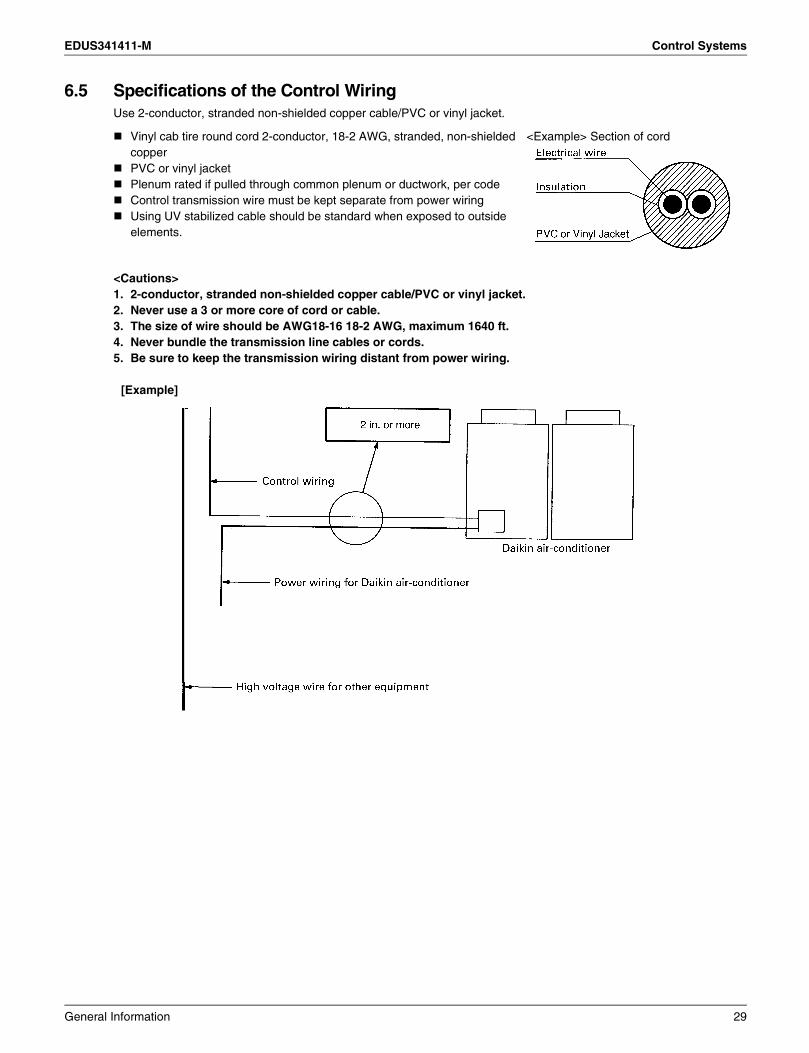
6.5 Specifications of the Control WiringUse 2-conductor, stranded non-shielded copper cable/PVC or vinyl jacket.
<Cautions>1. 2-conductor, stranded non-shielded copper cable/PVC or vinyl jacket.2. Never use a 3 or more core of cord or cable.3. The size of wire should be AWG18-16 18-2 AWG, maximum 1640 ft.4. Never bundle the transmission line cables or cords.5. Be sure to keep the transmission wiring distant from power wiring.
[Example]
Vinyl cab tire round cord 2-conductor, 18-2 AWG, stranded, non-shielded copperPVC or vinyl jacketPlenum rated if pulled through common plenum or ductwork, per codeControl transmission wire must be kept separate from power wiringUsing UV stabilized cable should be standard when exposed to outside elements.
<Example> Section of cord
General Information 29
Control Systems EDUS341411-M
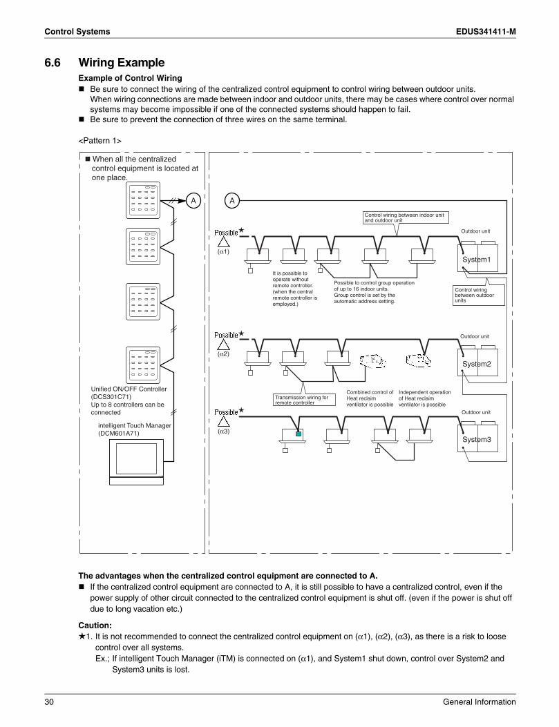
6.6 Wiring ExampleExample of Control Wiring
Be sure to connect the wiring of the centralized control equipment to control wiring between outdoor units.When wiring connections are made between indoor and outdoor units, there may be cases where control over normal systems may become impossible if one of the connected systems should happen to fail.Be sure to prevent the connection of three wires on the same terminal.
<Pattern 1>
The advantages when the centralized control equipment are connected to A.If the centralized control equipment are connected to A, it is still possible to have a centralized control, even if the power supply of other circuit connected to the centralized control equipment is shut off. (even if the power is shut off due to long vacation etc.)
Caution:1. It is not recommended to connect the centralized control equipment on (α1), (α2), (α3), as there is a risk to loose
control over all systems.Ex.; If intelligent Touch Manager (iTM) is connected on (α1), and System1 shut down, control over System2 and
System3 units is lost.
Control wiring between indoor unit and outdoor unit
Transmission wiring for remote controller
Control wiring between outdoor units
Outdoor unit
Outdoor unit
Outdoor unit
It is possible to operate without remote controller. (when the central remote controller is employed.)
Possible to control group operation of up to 16 indoor units.Group control is set by the automatic address setting.
Combined control of Heat reclaim ventilator is possible
Independent operation of Heat reclaim ventilator is possible
Unified ON/OFF Controller (DCS301C71) Up to 8 controllers can be connected
intelligent Touch Manager(DCM601A71)
When all the centralized control equipment is located at one place.
A A
(α1)
(α2)
(α3)
System1
System2
System3
30 General Information

EDUS341411-M Control Systems
<Pattern 2>
The advantages when the centralized control equipment are connected to A.If the centralized control equipment are connected to A, it is still possible to have a centralized control, even if the power supply of other circuit connected to the centralized control equipment is shut off. (even if the power is shut off due to long vacation etc.)
Caution:1. It is not recommended to connect the centralized control equipment on (α1), (α2), (α3), as there is a risk to loose
control over all systems.Ex.; If intelligent Touch Manager (iTM) is connected on (α1), and System1 shut down, control over System2 and
System3 units is lost.
Unified ON / OFF controller (DCS301C71)Up to 8 controllers can be connected.
Control wiring between indoor unit and outdoor unit
Transmission wiring for remote controller
Control wiring between outdoor units
Outdoor unit
Outdoor unit
Outdoor unit
It is possible to operate without remote controller. (when the central remote controller is employed.)
Possible to control group operation of up to 16 indoor units.Group control is set by the automatic address setting.
Combined control of Heat reclaim ventilator is possible
Independent operation of Heat reclaim ventilator is possible
A
A
When the centralized control equipment are located at several places.
(α1)
(α1)
(α2)
(α3)
(α2)
(α3)
iTM
System1
System2
System3
General Information 31

Control Systems EDUS341411-M
6.7 Length of Transmission WiringThe super wiring system, which integrates the control wiring between indoor unit and outdoor unit and the transmission wiring to the central controllers into one common wiring, should satisfy the following limitation.The longest extension of wiring: Not exceeding 3280ftTotal length of wiring: Not exceeding 6560ft
6.7.1 Example of Wiring
In the above system, the longest extension of wiring is 2950ft between (A) and (C), which satisfies the limit of 3280ft. And the total length is 3610ft, that is the total of 2950ft between (A) and (C) and 656ft between (B) and (D), which also satisfies the limit of 6560ft. The central controller functions properly, only when both the longest extension and the total length of wiring satisfies the limitation, as shown above.
Caution:When designing the system, be sure to check both the longest extension and the total length of wiring. If it exceeds the limitation, there is no other way but to split into several systems.
32 General Information

EDUS341411-M Control Systems
6.8 Connection Method6.8.1 Correct Wiring
Series wiring method only should be used.
[Example]
Note:Make sure that the outdoor to indoor communication wiring matches the refrigerant piping circuit. If communication wiring is crossed over different refrigerant circuits system errors and malfunctions can occur.
CentralizedController
VRV Outdoor unit
VRV Indoor unit
Connect the centralized controller to the outdoor-outdoor connection.
Connect outdoor units without branch connection.
Indoor-outdoor connection
Connect indoor units and outdoor units without branch connection.
Outdoor-outdoor connection
IN/OUTF1 F2OUT/OUTF1 F2
IN/OUTF1 F2
IN/OUTF1 F2OUT/OUTF1 F2
OUT/OUTF1 F2
General Information 33

Control Systems EDUS341411-M
6.8.2 Incorrect Wiring Example
Caution:Communication problems could occur.
[Incorrect Wiring 1]Series wiring method only should be used.
Caution:As shown above, the centralized control equipment should be connected to the wiring between the outdoor units, wherever possible. (If connected to the control wiring between indoor unit and the outdoor unit, it may not be able to control the units even on the normal circuit if the circuit connected to the centralized control equipment is out of order.)
CentralizedControl
Equipment
34 General Information

EDUS341411-M Control Systems
[Incorrect Wiring 2]
Caution:[Reason]Communication problems could occur.
[Incorrect Wiring 3]
Caution:[Reason]Communication problems could occur.
CentralizedControlEquipment
IN/OUTF1 F2OUT/OUTF1 F2
IN/OUTF1 F2OUT/OUTF1 F2
IN/OUTF1 F2OUT/OUTF1 F2
CentralizedControlEquipment
IN/OUTF1 F2OUT/OUTF1 F2
IN/OUTF1 F2OUT/OUTF1 F2
IN/OUTF1 F2OUT/OUTF1 F2
General Information 35

Control Systems EDUS341411-M
[Incorrect Wiring 4]
[Incorrect Wiring 5]
[Incorrect Wiring 6]
IN/OUTF1 F2OUT/OUTF1 F2
IN/OUTF1 F2OUT/OUTF1 F2
CentralizedControl
Equipment
VRV Outdoor unit
VRV Indoor unit
F1 F2
F1 F2
Connect the centralizedcontrol equipmentto the outdoor-outdoorconnection.
Connecting directly in the middle of indoor F1 or F2 line, without using F1 or F2 terminal, is prohibited.
Connect outdoor units without branch connection.
Indoor-outdoor connection
Connect indoor units and outdoor units without branch connection.
Outdoor-outdoor connection
CentralizedControl
Equipment
mismatch
VRV Outdoor unit
Refrigerant piping
VRV Indoor unit
IN/OUTF1 F2OUT/OUTF1 F2
IN/OUTF1 F2OUT/OUTF1 F2
F1 F2
F1 F2
Main
System A
2-00
~2-03
2-00 2-01 2-02 2-03
1-00 1-01 1-02 1-03
Sub
NO!Wiring this part is prohibited.
2-00
~2-03
1-00
~1-03
System B
Conflict
IN/OUTF1 F2OUT/OUTF1 F2
IN/OUTF1 F2OUT/OUTF1 F2
36 General Information
EDUS341411-M Control Systems
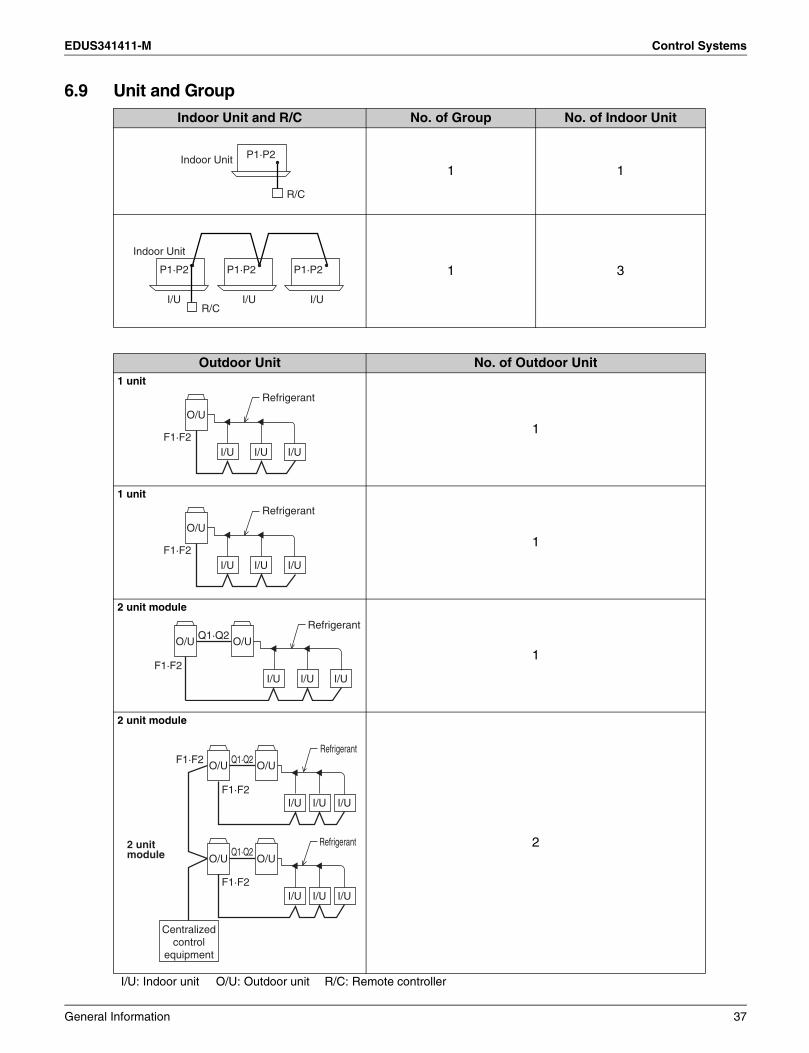
6.9 Unit and Group
I/U: Indoor unit O/U: Outdoor unit R/C: Remote controller
Indoor Unit and R/C No. of Group No. of Indoor Unit
1 1
1 3
Outdoor Unit No. of Outdoor Unit1 unit
1
1 unit
1
2 unit module
1
2 unit module
2
Indoor Unit
R/C
P1·P2
Indoor Unit
I/U I/U I/UR/C
P1·P2 P1·P2 P1·P2
I/U
O/U
I/U
Refrigerant
I/UF1·F2
I/U
O/U
I/U
Refrigerant
I/UF1·F2
I/U I/U I/U
O/U O/UQ1·Q2
F1·F2
Refrigerant
Centralized control
equipment
I/U I/U I/U
I/U I/U I/U
O/U O/U
O/U O/U
Q1·Q2
F1·F2
F1·F2
Q1·Q2
F1·F2
Refrigerant
Refrigerant2 unit module
General Information 37
Control Systems EDUS341411-M
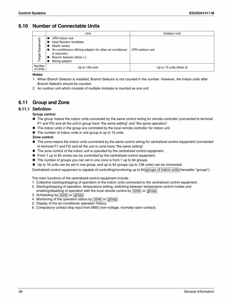
6.10 Number of Connectable Units
Notes:1. When Branch Selector is installed, Branch Selector is not counted in the number. However, the indoor units after
Branch Selector should be counted.2. An outdoor unit which consists of multiple modules is counted as one unit.
6.11 Group and Zone6.11.1 Definition
Group controlThe group means the indoor units connected by the same control wiring for remote controller (connected to terminal P1 and P2) and all the unit in group have “the same setting” and “the same operation”.The indoor units in the group are controlled by the local remote controller for indoor unit.The number of indoor units in one group is up to 16 units.
Zone controlThe zone means the indoor units connected by the same control wiring for centralized control equipment (connected to terminal F1 and F2) and all the unit in zone have “the same setting”.The zone control of the indoor unit is operated by the centralized control equipment.From 1 up to 64 zones can be controlled by the centralized control equipment.The number of groups you can set in one zone is from 1 up to 64 groups.Up to 16 units can be set in one group, and up to 64 groups (up to 128 units) can be connected.
Unit Outdoor Unit
Tar
get E
quip
men
t VRV indoor unitHeat Reclaim VentilatorSkyAir seriesAir-conditioners (Wiring adaptor for other air-conditioner is required.)Branch Selector (Note 1.)Wiring adaptor
VRV outdoor unit
Number of Units Up to 128 units Up to 10 units (Note 2)
Centralized control equipment is capable of controlling/monitoring up to 64 groups of indoor units (hereafter “groups”).
The main functions of the centralized control equipment include :1. Collective starting/stopping of operation of the indoor units connected to the centralized control equipment.2. Starting/stopping of operation, temperature setting, switching between temperature control modes and
enabling/disabling of operation with the local remote control by zone or group .3. Scheduling by zone or group .4. Monitoring of the operation status by zone or group .5. Display of the air-conditioner operation history.6. Compulsory contact stop input from BMS (non-voltage, normally-open contact).
38 General Information

EDUS341411-M Control Systems
6.11.2 Patterns of Group and Zone ∗ A group of indoor units include:
∗ Zone control with the centralized control equipment ∗ Zone control, which allows collective settings for more than one group, is available with the centralized control equipment, which facilitates the setting operations.
1 One indoor unit without a remote controller.
3 Up to 16 indoor units controlled with one or two remote controllers.
One setting makes the same setting for all of the units in one zone. Up to 128 zones can be set with one centralized control equipment.(The maximum number of groups in one zone is 64.)
Groups can be zoned at will with the centralized control equipment. Indoor units in one group can be divided into more than one zone. 1 Zone is not limited to 1 Group and vice versa.
2 One indoor unit controlled with one or two remote controllers.
Zone 1
Up to 16 units2 remote controllers
No remote controller Local remote controller Local remote controller
or
Indoor unit
Zone 5
Zone 2 Zone 3 Zone 4
General Information 39
Control Systems EDUS341411-M
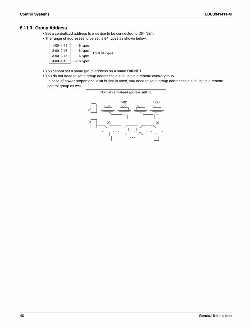
6.11.3 Group Address• Set a centralized address to a device to be connected to DIII-NET.• The range of addresses to be set is 64 types as shown below.
• You cannot set a same group address on a same DIII-NET.• You do not need to set a group address to a sub unit in a remote control group.
- In case of power proportional distribution is used, you need to set a group address to a sub unit in a remote control group as well.
1-00~1-15 ······16 types
Total 64 types2-00~2-15 ······16 types
3-00~3-15 ······16 types
4-00~4-15 ······16 types
Normal centralized address setting
1-00 1-01
1-031-02
40 General Information
EDUS341411-M Guide Specifications
7. Guide Specifications7.1 Guide Specifications
GeneralUnit shall be air cooled, split type multi-system air conditioner consisting of one outdoor unit and plural indoor units, each having capability to cool or heat independently for the requirements of the rooms.Up to 11 different type indoor units can be connected to one refrigerant circuit and controlled individually. Compressor shall be equipped with inverter controller, and capable of changing the rotating speed to follow variations in cooling and heating load.Outdoor unit shall be suitable for mix-match connection of following models.
Ceiling Mounted Cassette Type (Round Flow with Sensing)Ceiling Mounted Cassette Type (Round Flow)4 Way Ceiling Mounted Cassette Type (2’×2’)Slim Ceiling Mounted Duct TypeCeiling Mounted Duct Type (Middle and High Static Pressure)Ceiling Mounted Duct TypeCeiling Suspended TypeWall Mounted TypeFloor Standing TypeConcealed Floor Standing TypeVertical Air Handling Unit
Refrigerant : R410A
7.1.1 T Series Outdoor UnitThe refrigerant piping shall be extended up to 540ft with 164ft ( 1) level difference without any oil traps.
Air conditioner shall operate continuously at the ambient temperature of 23°F in cooling -4°F in heating.Both indoor unit and outdoor unit are assembled, tested, and charged with refrigerant at the factory.
1: The value is based on the case where the outdoor unit is located above indoor unit. Where the outdoor unit is located under the indoor unit, the level difference is a maximum of 130ft.
Outdoor UnitThe outdoor unit shall be a factory assembled unit housed in a sturdy weatherproof casing constructed form rust-proofed mild steel panels coated with a baked enamel finish.
The outdoor unit of shall have two of scroll compressors and be able to operate even in case that one of compressors is out of order. The outdoor unit shall be modular in design and should be allowed for side by side installation.
CompressorThe compressor shall be of highly efficient hermetic scroll type and equipped with inverter control capable of changing the speed in accordance to the cooling or heating load requirement.
The outdoor unit shall have the multi-step of capacity control to meet load fluctuation and indoor unit individual control.
Heat ExchangerThe heat exchanger shall be constructed with copper tubes mechanically bonded to aluminium fins to form a cross fin coil.
The aluminium fins shall be covered by anti-corrosion resin film.
Refrigerant CircuitThe refrigerant circuit shall include liquid and gas shut off valves and solenoid valves.All necessary safety devices shall be provided to ensure the safety operation of the system.
General Information 41

Guide Specifications EDUS341411-M
Safety DevicesThe following safety devices shall be part of the outdoor unit.High Pressure Switch, Overload Relay, Inverter Overload Protector, Fusible Plugs.
Oil Recovery SystemUnit shall be equipped with an oil recovery system to ensure stable operation with long refrigerant piping.
7.1.2 Indoor UnitsEach indoor unit shall be of the Ceiling Mounted Cassette Type (Round Flow with Sensing), or Ceiling Mounted Cassette Type (Round Flow), or 4 Way Ceiling Mounted Cassette Type (2’×2’), or Slim Ceiling Mounted Duct Type, or Ceiling Mounted Duct Type (Middle and High Static Pressure), or Ceiling Mounted Duct Type, or Ceiling Suspended Type, or Wall Mounted Type, or Floor Standing Type, or Concealed Floor Standing Type, or Vertical Air Handling Unit. It shall have electronic control valve which control refrigerant flow rate in respond to load variations of the room. The fan shall be of the dual suction multi blade type and statically and dynamically balanced to ensure low noise and vibration free operation.
The address of the indoor unit shall be set automatically in case of individual and group control.In case of centralized control, it shall be set by liquid crystal remote controller.
ControlComputerized PID control shall be used to maintain a correct room temperature.Unit shall be equipped with a self-diagnosis for easy and quick maintenance and service.The LCD (Liquid Crystal Display) remote controller shall memorize the latest malfunction code for easy maintenance.
It shall be able to control up to 16 indoor units and change fan speed and angle of swing flap individually in the group.
Central Remote Controller (Option)A multi-functional centralized control equipment (central remote controller) shall be supplied as optional accessory.
It shall be able to control up to 64 zones of 64 groups (each group consists of Max. 16 units) or 128 No.s of indoor units with the following functions.a) Temperature setting for each zone, or group, or indoor unit.b) On / off as a zone or individual unit.c) Indication of operating condition.d) Select one of 10 operation modes for each zone.The controller shall have wide screen liquid crystal display and can be wired by a non-polar 2-wire transmission cable to a distance of 1 km away from the indoor unit.
Unified ON / OFF Controller (Option)Unified ON / OFF controller shall be supplied as optional accessory.It shall be able to control up to 16 groups (each group consists of Max. 16 indoor units) or 128 No.s of indoor units with the following functions.a) On/off as a zone or individual unit.b) Indication of operation condition of each group.c) Select one of 4 operation modes.
It shall be wired by a non-polar 2-wire transmission cable to a distance of 1 km away from indoor unit.
Schedule Timer (Option)A schedule timer shall be supplied as optional accessory.
It shall be able to set operation schedule of up to 128 No.s of indoor units.The operation schedule shall include twice on/off a day and holiday.It shall be able to set 8 pattern of schedule combined with centralized controller.
42 General Information

EDUS341411-M Caution for Refrigerant Leaks
8. Caution for Refrigerant Leaks8.1 Introduction
Points to note in connection with refrigerant leaks
The VRV System, like other air conditioning systems, uses R410A as refrigerant. R410A itself is an entirely safe non-toxic, non-combustible refrigerant. Nevertheless care must be taken to ensure that air conditioning facilities are installed in a room which is sufficiently large. This assures that the maximum concentration level of refrigerant gas is not exceeded, in the unlikely event of major leak in the system and this in accordance to the local applicable regulations and standards.
Maximum concentration levelThe maximum charge of refrigerant and the calculation of the maximum concentration of refrigerant is directly related to the humanly occupied space in to which it could leak.The unit of measurement of the concentration is lb/1000ft3 (the weight in Ib. of the refrigerant gas in 1ft3 volume of the occupied space).Compliance to the local applicable regulations and standards for the maximum allowable concentration level is required.
The installer and system specialist shall secure safety against leakage according to local regulations or standards. The following standards may be applicable if local regulations are not available.
Pay special attention to the place, such as a basement, etc. where refrigerant can stay, since refrigerant is heavier than air.
Direction of therefrigerant flow
Room where refrigerant leak has occurred(outflow of all the refrigerant from the system)
General Information 43
Caution for Refrigerant Leaks EDUS341411-M
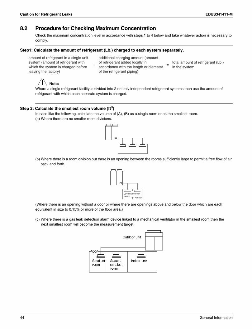
8.2 Procedure for Checking Maximum ConcentrationCheck the maximum concentration level in accordance with steps 1 to 4 below and take whatever action is necessary to comply.
Step1: Calculate the amount of refrigerant (Lb.) charged to each system separately.
Note:Where a single refrigerant facility is divided into 2 entirely independent refrigerant systems then use the amount of refrigerant with which each separate system is charged.
Step 2: Calculate the smallest room volume (ft3)In case like the following, calculate the volume of (A), (B) as a single room or as the smallest room.(a) Where there are no smaller room divisions.
(b) Where there is a room division but there is an opening between the rooms sufficiently large to permit a free flow of air back and forth.
(Where there is an opening without a door or where there are openings above and below the door which are each equivalent in size to 0.15% or more of the floor area.)
(c) Where there is a gas leak detection alarm device linked to a mechanical ventilator in the smallest room then the next smallest room will become the measurement target.
amount of refrigerant in a single unitsystem (amount of refrigerant withwhich the system is charged beforeleaving the factory)
+
additional charging amount (amountof refrigerant added locally inaccordance with the length or diameterof the refrigerant piping)
=total amount of refrigerant (Lb.)in the system
Opening betweenrooms
Partition
44 General Information

EDUS341411-M Caution for Refrigerant Leaks
Step 3: Calculating the refrigerant density using the results of the calculations in steps 1 and 2 above.
If the result of the above calculation exceeds the maximum concentration level then make similar calculations for the second then third smallest room and so until the result falls short of the maximum concentration.
Step 4: Dealing with the situations where the result exceeds the maximum concentration level.Where the installation of a facility results in a concentration in excess of the maximum concentration level then it will be necessary to revise the system.Please consult your Daikin supplier.
total volume of refrigerant in therefrigerant system
≤ maximum concentration level (Lb./ft3)size (ft3) of smallest room in whichthere is an indoor unit installed
General Information 45
Safety Devices Setting EDUS341411-M
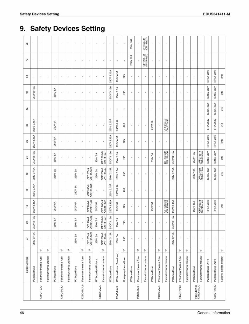
9. Safety Devices SettingS
afet
y D
evic
es07
0912
1518
2430
3642
4854
7296
FX
FQ
-TV
JU
PC
boa
rd fu
se25
0V 3
.15A
250V
3.1
5A25
0V 3
.15A
250V
3.1
5A25
0V 3
.15A
250V
3.1
5A25
0V 3
.15A
250V
3.1
5A-
250V
3.1
5A-
--
Fan
mot
or th
erm
al fu
se°F
--
--
--
--
--
--
-
Fan
mot
or th
erm
al p
rote
ctor
°F-
--
--
--
--
--
--
FX
FQ
-PV
JU
PC
boa
rd fu
se-
250V
5A
250V
5A
-25
0V 5
A25
0V 5
A25
0V 5
A25
0V 5
A-
250V
5A
--
-
Fan
mot
or th
erm
al fu
se°F
--
--
--
--
--
--
-
Fan
mot
or th
erm
al p
rote
ctor
°F-
--
--
--
--
--
--
FX
ZQ
-MV
JU9
PC
boa
rd fu
se25
0V 5
A25
0V 5
A25
0V 5
A25
0V 5
A25
0V 5
A-
--
--
--
-
Fan
mot
or th
erm
al fu
se°F
--
--
--
--
--
--
-
Fan
mot
or th
erm
al p
rote
ctor
°FO
FF:2
66±9
ON
:181
.4±3
6O
FF:2
66±9
ON
:181
.4±3
6O
FF:2
66±9
ON
:181
.4±3
6O
FF:2
66±9
ON
:181
.4±3
6O
FF:2
66±9
ON
:181
.4±3
6-
--
--
--
-
FX
DQ
-MV
JUP
C b
oard
(A
1P)
fuse
250V
5A
250V
5A
250V
5A
-25
0V 5
A25
0V 5
A-
--
--
--
Fan
mot
or th
erm
al p
rote
ctor
°FO
FF
:266
±9
ON
:181
±27
OF
F:2
66±
9O
N:1
81±
27O
FF
:266
±9
ON
:181
±27
-O
FF
:266
±9
ON
:181
±27
OF
F:2
66±
9O
N:1
81±
27-
--
--
--
FXM
Q-P
AV
JU
PC
boa
rd fu
se25
0V 3
.15A
250V
3.1
5A25
0V 3
.15A
250V
3.1
5A25
0V 3
.15A
250V
3.1
5A25
0V 3
.15A
250V
3.1
5A-
250V
3.1
5A25
0V 3
.15A
--
PC
boa
rd fu
se (
Fan
driv
er)
250V
5A
250V
5A
250V
5A
250V
6.3
A25
0V 6
.3A
250V
6.3
A25
0V 6
.3A
250V
6.3
A-
250V
6.3
A25
0V 6
.3A
--
Dra
in p
ump
ther
mal
fuse
°F29
329
329
329
329
329
329
329
3-
293
293
--
FX
MQ
-MV
JU
PC
boa
rd fu
se-
--
--
--
--
--
250V
10A
250V
10A
Fan
mot
or th
erm
al fu
se°F
--
--
--
--
--
--
-
Fan
mot
or th
erm
al p
rote
ctor
°F-
--
--
--
--
--
OFF
:275
±14
(ON
:189
±27)
OFF
:275
±14
(ON
:189
±27)
FX
HQ
-MV
JU
PC
boa
rd fu
se-
-25
0V 5
A-
-25
0V 5
A-
250V
5A
--
--
-
Fan
mot
or th
erm
al fu
se°F
--
--
--
--
--
--
-
Fan
mot
or th
erm
al p
rote
ctor
°F-
-O
FF
:266
±9
ON
:176
±36
--
OF
F:2
66±
9O
N:1
76±
36-
OF
F:2
66±
9O
N:1
76±
36-
--
--
FX
AQ
-PV
JU
PC
boa
rd fu
se25
0V 3
.15A
250V
3.1
5A25
0V 3
.15A
-25
0V 3
.15A
250V
3.1
5A-
--
--
--
Fan
mot
or th
erm
al fu
se°F
--
--
--
--
--
--
-
Fan
mot
or th
erm
al p
rote
ctor
°F-
--
--
--
--
--
--
FX
LQ-M
VJU
FX
NQ
-MV
JU
PC
boa
rd fu
se-
-25
0V 1
0A-
250V
10A
250V
10A
--
--
--
-
Fan
mot
or th
erm
al p
rote
ctor
°F-
-O
FF:2
75±1
8O
N:2
48 o
r les
s-
OFF
:275
±18
ON:
248
or le
ssO
FF:2
75±1
8O
N:24
8 or
less
--
--
--
-
FX
TQ
-PA
VJU
PC
boa
rd fu
se (
A1P
)-
-T3
.15A
, 250
V-
T3.1
5A, 2
50V
T3.1
5A, 2
50V
T3.1
5A, 2
50V
T3.1
5A, 2
50V
T3.1
5A, 2
50V
T3.1
5A, 2
50V
T3.1
5A, 2
50V
--
PC
boa
rd fu
se (
A2P
)-
-T3
.15A
, 250
V-
T3.1
5A, 2
50V
T3.1
5A, 2
50V
T3.1
5A, 2
50V
T3.1
5A, 2
50V
T3.1
5A, 2
50V
T3.1
5A, 2
50V
T3.1
5A, 2
50V
--
Fan
drive
r ove
rload
pro
tect
or°F
--
248
-24
824
824
824
824
824
824
8-
-
46 General Information


RXYQ-TYDN3 phase, 460V, 60Hz
RXYQ-TTJU3 phase, 208/230V, 60Hz
1. Air conditioners should not be installed in areas where corrosive gases, such as acid gas or alkaline gas, are produced.2. If the outdoor unit is to be installed close to the sea shore, direct exposure to the sea breeze should be avoided. If you need to install the outdoor unit close to the sea shore, contact your local distributor.
Cautions on product corrosion
Warning Ask a qualified installer or contractor to install this product. Do not try to install the product yourself. Improper installation can result in water or refrigerant leakage, electrical shock, fire or explosion.
Use only those parts and accessories supplied or specified by Daikin. Ask a qualified installer or contractor to install those parts and accessories. Use of unauthorised parts and accessories or improper installation of parts and accessories can result in water or refrigerant leakage, electrical shock, fire or explosion.
Read the user's manual carefully before using this product. The user's manual provides important safety instructions and warnings. Be sure to follow these instructions and warnings.
If you have any enquiries, please contact your local importer, distributor and/or retailer.
Specifications, designs and other content appearing in this brochure are current as of January 2015 but subject to change without notice.
© All rights reserved 01/15 FS