general catalogue c008n - tooling system...valvefinisher toolingsystem toolingsystem 1592 29 f 41...
TRANSCRIPT
1590

1591
MILLING TOOLSTOOLING SYSTEMValve Finisher ............................................... 1592CARTRIDGE ................................................ 1596BORING UNIT .............................................. 1602MI TYPE BORING BARS............................... 1606CLASSIFICATION OF QUICK CHANGE /
MODULAR TOOLING SYSTEM .............. 1608FACE MILL................................................... 1609FACE MILLING ADAPTER ............................ 1610SIDE CUTTER.............................................. 1612BORING TOOL............................................. 1613ABS License KOMET .................................... 1614HSK SYSTEM .............................................. 1618

Valve Finisher
TOOLINGSY
STEM
TOOLING SYSTEM
1592
29 ─ 41
HSK63A
30 LPR
ø6
LPR WT(kg)
HVF06-HSK63A110A3 a 80 1.5
HVF06-HSK63A110A4 a 80 1.5
HVF06-HSK63A180A3 a 150 2.6
HVF06-HSK63A180A4 a 150 2.6
MPCA MPCB MPCC MPCD MPCE MPCF
MPCFMPCD MPCC
MPCB
MPCE
MPC
A
HSC05016HW a 5.8 M5×0.8 14 2 2 2.5
yTool Holder
* The Mitsubishi Materials tool holder (Patent held in Japan)(p) is manufactured under license by NT TOOL CORPORATION.
Screw for Reamer
Coolant Hole
* A variety of other tool holders, such as BT shanks with their distinctive double face contact, can be mounted as well.
Reamer adjustment screws can be operated using a wrench from both the reamer insertion hole side and the mounting side. The reamer adjustment screw is an accessory (1 piece), which can also be additionally purchased as a stand-alone item. A hexagon socket set screw (M4) is included with the tool holder. It should be used as a stopper when discharging coolant with the use of an external oil supply.
Spare Parts (Reamer Adjustment Screws)
Order Number
Sto
ck Coolant Hole(Hole) Installation Balance Accuracy
Fig.1 (3 Hole)
HSK63A(With Coolant Pipe)
G2.5(5000min-1)
Fig.2 (4 Hole)
Fig.1 (3 Hole)
Fig.2 (4 Hole)
Geometry Order Number
Sto
ck
Fig.1
Fig.2
Right hand tool holder only.
a : Inventory maintained in Japan.
(mm)
(mm)

Valve Finisher
TOOLINGSY
STEM
TOOLING SYSTEM
1593
45°
RT9005
MB4020
EF05
a
1 2 3 4
HVF06-HSK63A110A3 3 u × u ×
HVF06-HSK63A180A3 3 u × u ×
HVF06-HSK63A110A4 4 u u × u
HVF06-HSK63A180A4 4 u u × u
Seat Ring (Sintered Material)
Produced-to-Order Products Please inquire with our Sales Department regarding production.
Compatible Reamer Range : ≤ ø6 (Guide Hole Diameter)
Compatible Head Range : ø20 ≤ Head Diameter < ø35 (Seat Hole : 45°-Surface Gauge Diameter)Tool Bits : 3 types
For Valve Guide Hole Reaming
For Seat Surface Machining
Optimization and strengthening of the hard phase (WC) particle diameter and bonded phase (Co) have improved the wear resistance and fracture resistance, for the creation of a unique cemented carbide.
High edge toughness has been achieved with a newly-developed special binder. The even sharper cutting edge shape can suppress the creation of burrs and ensure high accuracy. CBN, which is included with a high chemical content, has outstanding welding resistance so that a constant dimensional accuracy can be maintained.
The seat surface is composed of 3 faces at different angles (Cutting with 3 types of edges).
The hard coating with smooth surface properties can maintain an excellent fi nished surface over extended periods of time.
An ultra-high hardness, ultra micro-particle cemented carbide that contains specialized components. Just as with RT9005, its wear resistance and fracture resistance have been improved.
Coating (TiN)
u = Suitable × = Unsuitable
* HVF06-HSK63A110Ao : Suitable for cases with no processing beyond the angle plate
* HVF06-HSK63A180Ao : Suitable for cases with processing beyond the angle plate
Install screws in any unused coolant holes.* Hexagon socket set screws (M4) are included as separately-packaged accessories.
Relationship between number of head cutting edge grooves and tool holders
Important!
Order Number Coolant Hole(Hole)
Number of Cutting Edge Grooves on Head
øGauge Diameter

Valve Finisher
TOOLINGSY
STEM
TOOLING SYSTEM
1594
30 80
137
170
(6.0)
(3.0)
100
ø52ø4
2
ø27
45°45°
y
y
RT9005 92.2 2.040 ─ 60 0.03 ─ 0.05
EF05 94.0 2.5
1 MB4020
60 ─ 120 0.05 ─ 0.102 MB825
2 MB835
(When Tool Holder : HVF06-HSK63A110A3 is suitable)
Rough Processing
Finish Processing
Setup Reference Diagram
ø5.8
(Rea
mer
)ø6
(Rea
mer
)
Work Material
Reamer Material Cutting Speedvc
(m/min)
Feed per Toothfz
(mm/t.)Grade Hardness (HRA) Bending Strength(Gpa)
Steel-based Sintered Alloy
Cast Iron
Work Material Priority CBN Material for BitsCutting Speed
vc(m/min)
Feed per Toothfz
(mm/t.)
Sintered Alloy
Valve Guide Hole Reaming
Seat Surface Machining
* Select materials in accordance with seat material characteristics.
RECOMMENDED CUTTING CONDITIONS
(mm)

Valve Finisher
TOOLINGSY
STEM
TOOLING SYSTEM
1595
Procedure
Mount the head on the tool holder.
Secured Position Mounting / Removal Position
During use, line up the markings on the head and tool holder to secure them in place. When mounting and removing them, turn them to the side marked “FREE”.
Attach the reamer. Tightening and removing screws follow opposite procedures from the usual.
STEP 1 STEP 2 STEP 3

CARTRIDGE
TOOLINGSY
STEM
TOOLING SYSTEM
1596
LLSCN
LLSSN
LLSTN
z
x
R L H B LF MHD ASP S10 MHH HF WF RE DMIN
PTFN
PTFNR/L10CA11 a a
TNMATNMGTNMMTNGATNGG
1103pp 12.5 11 50 20 8 2 5 10 14 0.4 40 ─ ─ LLCL12S HLS1 LLCS105 LLR1 KS1 HSC06016PTFNR/L12CA16 a a 1604pp 15.5 16 55 20 8 2 6 12 20 0.8 50 ─ ─ LLCL13S HLS2 LLCS105 LLR1 KS1 HSC06020PTFNR/L16CA16 a a 1604pp 16 17 63 25 8 2.5 ─ 16 25 0.8 60 LLSTN32 LLP13 LLCL13 ─ LLCS106 LLR1 KS2 HBH08025PTFNR/L20CA22 a 2204pp 20 19 70 30 10 2.5 ─ 20 25 0.8 70 LLSTN42 LLP14 LLCL14 ─ LLCS108S LLR2 KS2 zHKY30R HBH08030
PTGN
PTGNR/L12CA16 a a 1604pp 15.5 16 55 20 8 2 6 12 20 0.8 50 ─ ─ LLCL13S HLS2 LLCS105 LLR1 KS1 HSC06020PTGNR/L16CA16 a a 1604pp 16 17 63 25 8 2.5 ─ 16 25 0.8 60 LLSTN32 LLP13 LLCL13 ─ LLCS106 LLR1 KS2 HBH08025
PSKN
PSKNR/L10CA09 a a
SNMASNMGSNMMSNGASNGG
0903pp 12.5 11 50 20 8 2 5 10 14 0.8 40 ─ ─ LLCL13S HLS2 LLCS105 LLR1 KS1 HSC06016PSKNR/L12CA12 a a 1204pp 15.5 16 55 20 8 2 6 12 20 0.8 50 ─ ─ LLCL14S HLS3 LLCS106S LLR1 KS1 HSC06020PSKNR/L16CA12 a a 1204pp 16 17 63 25 8 2.5 ─ 16 25 0.8 60 LLSSN42 LLP14 LLCL14 ─ LLCS108S LLR2 KS2 zHKY30R HBH08025
PCLN
PCLNR/L12CA12 a a
CNMACNMGCNMMCNGG
1204pp 15.5 16 55 20 8 2 6 12 20 0.8 50 ─ ─ LLCL14S HLS3 LLCS106S LLR1 KS1 HSC06020PCLNR/L16CA12 a a 1204pp 16 17 63 25 8 2.5 ─ 16 25 0.8 60 LLSCN42 LLP14 LLCL14 ─ LLCS108S LLR2 KS2 zHKY30R HBH08025PCLNR/L20CA12 a 1204pp 20 19 70 30 10 2.5 ─ 20 25 0.8 70 LLSCN42 LLP14 LLCL14 ─ LLCS108S LLR2 KS2 zHKY30R HBH08030
PSSN
PSSNR/L10CA09 a a
SNMASNMGSNMMSNGASNGG
0903pp 12.5 11 44 20 8 2 5 10 14 0.8 40 ─ ─ LLCL13S HLS2 LLCS105 LLR1 KS1 HSC06016PSSNR/L12CA12 a a 1204pp 15.5 16 47 20 8 2 6 12 20 0.8 50 ─ ─ LLCL14S HLS3 LLCS106S LLR1 KS1 HSC06020PSSNR/L16CA12 a a 1204pp 16 17 53 25 8 2.5 ─ 16 25 0.8 60 LLSSN42 LLP14 LLCL14 ─ LLCS108S LLR2 KS2 zHKY30R HBH08025
PTTN
PTTNR12CA16 a
TNMATNMGTNMMTNGATNGG
1604pp 15.5 16 55 20 8 2 6 12 13 0.8 50 ─ ─ LLCL13S HLS2 LLCS105 LLR1 KS1 HSC06020PTTNR16CA16 a 1604pp 16 17 63 25 8 2.5 ─ 16 15 0.8 60 LLSTN32 LLP13 LLCL13 ─ LLCS106 LLR1 KS2 HBH08025
PSYN
PSYNR10CA09 a
SNMASNMGSNMMSNGASNGG
0903pp 12.5 11 50 20 8 2 5 10 14 0.8 40 ─ ─ LLCL13S HLS2 LLCS105 LLR1 KS1 HSC06016PSYNR12CA12 a 1204pp 15.5 16 55 20 8 2 6 12 20 0.8 50 ─ ─ LLCL14S HLS3 LLCS106S LLR1 KS1 HSC06020PSYNR16CA12 a 1204pp 16 17 63 25 8 2.5 ─ 16 25 0.8 60 LLSSN42 LLP14 LLCL14 ─ LLCS108S LLR2 KS2 zHKY30R HBH08025
DMIN
DMIN
DMIN
DMIN
DMIN
DMIN
DMIN
HF
HF
HF
HF
HF
HF
HFW
FW
FW
FW
FW
FW
FW
F 90°
90°
60°
45°
45°
45°
45°
45°
45°
45°
45°
85°
RE
RE
RE
RE
RE
RE
RE
RES10
S10
S10
S10
S10
S10
S10
MHH
MHH
MHH
MHH
MHH
MHH
MHH
LF
LF
LF
LF
LF
LF
LF
MHD
MHD
MHD
MHD
MHD
MHD
MHD
ASP
ASP
ASP
ASP
ASP
ASP
ASP
20°
20°
20°
20°
20°
20°
20°
16CA
16CA
16CA
16CA
16CA
16CA
16CA
20CA
20CA
10CA
10CA
10CA
10CA
12CA
12CA
12CA
12CA
12CA
12CA
12CA
BB
BB
BB
B
BB
BB
BB
B
H
H
H
H
H
H
H
H
H
H
H
H
H
H
75°
95°
LL ISO type Lever lock type
Negative insert.Large breaker selection.Suitable for steel and cast iron.
* Clamp Torque (N • m) : LLCS105=1.5, LLCS106=2.2, LLCS106S=2.2, LLCS108S=3.3
Lever lock type
Shim
Insert Clamp Screw
Lever
Shim Pin
Cartridge
a : Inventory maintained in Japan.
a
a
a
Type Order NumberStock
Geometry Insert NumberDimensions(mm)
*
Shim ShimPin
ClampLever
LeverSpring
ClampScrew
RadialScrew
AxialScrew Wrench Set Bolt
Right hand tool holder shown.
Right hand tool holder shown.
Right hand tool holder shown.
Right hand tool holder shown.
Right hand tool holder shown.
Right hand tool holder only.
Right hand tool holder only.

CARTRIDGE
TOOLINGSY
STEM
TOOLING SYSTEM
1597
LLSCN
LLSSN
LLSTN
z
x
R L H B LF MHD ASP S10 MHH HF WF RE DMIN
PTFN
PTFNR/L10CA11 a a
TNMATNMGTNMMTNGATNGG
1103pp 12.5 11 50 20 8 2 5 10 14 0.4 40 ─ ─ LLCL12S HLS1 LLCS105 LLR1 KS1 HSC06016PTFNR/L12CA16 a a 1604pp 15.5 16 55 20 8 2 6 12 20 0.8 50 ─ ─ LLCL13S HLS2 LLCS105 LLR1 KS1 HSC06020PTFNR/L16CA16 a a 1604pp 16 17 63 25 8 2.5 ─ 16 25 0.8 60 LLSTN32 LLP13 LLCL13 ─ LLCS106 LLR1 KS2 HBH08025PTFNR/L20CA22 a 2204pp 20 19 70 30 10 2.5 ─ 20 25 0.8 70 LLSTN42 LLP14 LLCL14 ─ LLCS108S LLR2 KS2 zHKY30R HBH08030
PTGN
PTGNR/L12CA16 a a 1604pp 15.5 16 55 20 8 2 6 12 20 0.8 50 ─ ─ LLCL13S HLS2 LLCS105 LLR1 KS1 HSC06020PTGNR/L16CA16 a a 1604pp 16 17 63 25 8 2.5 ─ 16 25 0.8 60 LLSTN32 LLP13 LLCL13 ─ LLCS106 LLR1 KS2 HBH08025
PSKN
PSKNR/L10CA09 a a
SNMASNMGSNMMSNGASNGG
0903pp 12.5 11 50 20 8 2 5 10 14 0.8 40 ─ ─ LLCL13S HLS2 LLCS105 LLR1 KS1 HSC06016PSKNR/L12CA12 a a 1204pp 15.5 16 55 20 8 2 6 12 20 0.8 50 ─ ─ LLCL14S HLS3 LLCS106S LLR1 KS1 HSC06020PSKNR/L16CA12 a a 1204pp 16 17 63 25 8 2.5 ─ 16 25 0.8 60 LLSSN42 LLP14 LLCL14 ─ LLCS108S LLR2 KS2 zHKY30R HBH08025
PCLN
PCLNR/L12CA12 a a
CNMACNMGCNMMCNGG
1204pp 15.5 16 55 20 8 2 6 12 20 0.8 50 ─ ─ LLCL14S HLS3 LLCS106S LLR1 KS1 HSC06020PCLNR/L16CA12 a a 1204pp 16 17 63 25 8 2.5 ─ 16 25 0.8 60 LLSCN42 LLP14 LLCL14 ─ LLCS108S LLR2 KS2 zHKY30R HBH08025PCLNR/L20CA12 a 1204pp 20 19 70 30 10 2.5 ─ 20 25 0.8 70 LLSCN42 LLP14 LLCL14 ─ LLCS108S LLR2 KS2 zHKY30R HBH08030
PSSN
PSSNR/L10CA09 a a
SNMASNMGSNMMSNGASNGG
0903pp 12.5 11 44 20 8 2 5 10 14 0.8 40 ─ ─ LLCL13S HLS2 LLCS105 LLR1 KS1 HSC06016PSSNR/L12CA12 a a 1204pp 15.5 16 47 20 8 2 6 12 20 0.8 50 ─ ─ LLCL14S HLS3 LLCS106S LLR1 KS1 HSC06020PSSNR/L16CA12 a a 1204pp 16 17 53 25 8 2.5 ─ 16 25 0.8 60 LLSSN42 LLP14 LLCL14 ─ LLCS108S LLR2 KS2 zHKY30R HBH08025
PTTN
PTTNR12CA16 a
TNMATNMGTNMMTNGATNGG
1604pp 15.5 16 55 20 8 2 6 12 13 0.8 50 ─ ─ LLCL13S HLS2 LLCS105 LLR1 KS1 HSC06020PTTNR16CA16 a 1604pp 16 17 63 25 8 2.5 ─ 16 15 0.8 60 LLSTN32 LLP13 LLCL13 ─ LLCS106 LLR1 KS2 HBH08025
PSYN
PSYNR10CA09 a
SNMASNMGSNMMSNGASNGG
0903pp 12.5 11 50 20 8 2 5 10 14 0.8 40 ─ ─ LLCL13S HLS2 LLCS105 LLR1 KS1 HSC06016PSYNR12CA12 a 1204pp 15.5 16 55 20 8 2 6 12 20 0.8 50 ─ ─ LLCL14S HLS3 LLCS106S LLR1 KS1 HSC06020PSYNR16CA12 a 1204pp 16 17 63 25 8 2.5 ─ 16 25 0.8 60 LLSSN42 LLP14 LLCL14 ─ LLCS108S LLR2 KS2 zHKY30R HBH08025
zHKY25RxHKY20FzHKY25RxHKY20FzHKY25RxHKY20F
zHKY25RxHKY20FzHKY25RxHKY20F
zHKY20RzHKY25RzHKY25RxHKY20F
zHKY25RxHKY20F
zHKY20RzHKY25RzHKY25RxHKY20F
zHKY25RxHKY20FzHKY25RxHKY20F
zHKY20RzHKY25RzHKY25RxHKY20F
Type Order NumberStock
Geometry Insert NumberDimensions(mm)
*
Shim ShimPin
ClampLever
LeverSpring
ClampScrew
RadialScrew
AxialScrew Wrench Set Bolt
Right hand tool holder shown.
Right hand tool holder shown.
Right hand tool holder shown.
Right hand tool holder shown.
Right hand tool holder shown.
Right hand tool holder only.
Right hand tool holder only.

CARTRIDGE
TOOLINGSY
STEM
TOOLING SYSTEM
1598
PS
PT
R L H B LF MHD ASP S10 MHH HF WF RE DMIN
CTGP
CTGPR10CA11 a
TPMNTPMRTPGN
1103pp 12.5 11 50 20 8 2 5 10 14 0.4 38 ─ ─ TSS05006 KS1 BC4 TKY10R HSC06016CTGPR12CA16 a 1603pp 15.5 16 55 20 8 2 6 12 20 0.8 50 ─ ─ TSS06010 KS1 BC5 TKY20R HSC06020CTGPR16CA16 a 1603pp 16 17 63 25 8 2 ─ 16 25 0.8 55 PT32 BCP201 TSS06010 KS2 BC6 TKY20R HBH08025
CSKP
CSKPR10CA09 a
SPMNSPMRSPGN
0903pp 12.5 11 50 20 8 2 5 10 14 0.8 38 ─ ─ TSS05006 KS1 BC4L TKY10R HSC06016CSKPR16CA12 a 1203pp 16 17 63 25 8 2 ─ 16 25 0.8 55 PS42 BCP251 TSS06010 KS2 BC6 TKY20R HBH08025
CSSP
CSSPR10CA09 a 0903pp 12.5 11 44 20 8 2 5 10 14 0.8 38 ─ ─ TSS05006 KS1 BC4L TKY10R HSC06016
DMIN
DMIN
DMIN
HF
HF
HF
WF
WF
WF
45°
45°
90°
75°
45°
RE
RE
RE
S10
S10
S10
MHH
MHH
MHH
LF
LF
LF
MHD
MHD
MHD
ASP
ASP
ASP
20°
20°
20°
16CA
16CA
10CA
10CA
12CA
BB
B
BB
H
H
H
H
H
Type Order NumberStock
Geometry Insert NumberDimensions(mm)
*
Shim ShimPin
RadialScrew
AxialScrew Clamp Set Wrench Set Bolt
Right hand tool holder only.
Right hand tool holder only.
Right hand tool holder only.
BC ISO type Clamp on type
11°positive insert.Suitable for steel, cast iron, aluminium alloys and copper alloys.
* Clamp Torque (N • m) : BC4=2.5, BC4L=2.5, BC5=5.0, BC6=5.0
Clamp on type
Insert
Clamp ScrewCartridgeClamp Bridge
a : Inventory maintained in Japan.
a
a

CARTRIDGE
TOOLINGSY
STEM
TOOLING SYSTEM
1599
PS
PT
R L H B LF MHD ASP S10 MHH HF WF RE DMIN
CTGP
CTGPR10CA11 a
TPMNTPMRTPGN
1103pp 12.5 11 50 20 8 2 5 10 14 0.4 38 ─ ─ TSS05006 KS1 BC4 TKY10R HSC06016CTGPR12CA16 a 1603pp 15.5 16 55 20 8 2 6 12 20 0.8 50 ─ ─ TSS06010 KS1 BC5 TKY20R HSC06020CTGPR16CA16 a 1603pp 16 17 63 25 8 2 ─ 16 25 0.8 55 PT32 BCP201 TSS06010 KS2 BC6 TKY20R HBH08025
CSKP
CSKPR10CA09 a
SPMNSPMRSPGN
0903pp 12.5 11 50 20 8 2 5 10 14 0.8 38 ─ ─ TSS05006 KS1 BC4L TKY10R HSC06016CSKPR16CA12 a 1203pp 16 17 63 25 8 2 ─ 16 25 0.8 55 PS42 BCP251 TSS06010 KS2 BC6 TKY20R HBH08025
CSSP
CSSPR10CA09 a 0903pp 12.5 11 44 20 8 2 5 10 14 0.8 38 ─ ─ TSS05006 KS1 BC4L TKY10R HSC06016
Type Order NumberStock
Geometry Insert NumberDimensions(mm)
*
Shim ShimPin
RadialScrew
AxialScrew Clamp Set Wrench Set Bolt
Right hand tool holder only.
Right hand tool holder only.
Right hand tool holder only.

CARTRIDGE
TOOLINGSY
STEM
TOOLING SYSTEM
1600
R L H B LF MHD ASP S10 MHH HF WF RE DMIN
STFP
STFPR/L10CA11 a a 1103pp 12.5 11 50 20 8 2 5 10 14 0.4 35 CS300890T TSS05006 KS1 HSC06016STFPR/L12CA16 a a
TPMTTPGX
1603pp 15.5 16 55 20 8 2 6 12 20 0.8 50 TS4 TSS06010 KS1 HSC06020
STGP
STGPR10CA11 a 1103pp 12.5 11 50 20 8 2 5 10 14 0.4 35 CS300890T TSS05006 KS1 HSC06016STGPR12CA16 a
TPMTTPGX
1603pp 15.5 16 55 20 8 2 6 12 20 0.8 50 TS4 TSS06010 KS1 HSC06020STGPR16CA16 a 1603pp 16 17 63 25 8 2 ─ 16 25 0.8 55 TS4 TSS06012 KS2 HBH08025
SSKP
SSKPR10CA09 a
SPMTSPGX
0903pp 12.5 11 50 20 8 2 5 10 14 0.8 35 TS4 TSS05006 KS1 HSC06016SSKPR12CA12 a 1203pp 15.5 16 55 20 8 2 6 12 20 0.8 50 TS5 TSS06010 KS1 HSC06020
SSSP
SSSPR10CA09 a 0903pp 12.5 11 44 20 8 2 5 10 14 0.8 35 TS4 TSS05006 KS1 HSC06016SSSPR12CA12 a 1203pp 15.5 16 47 20 8 2 6 12 20 0.8 50 TS5 TSS06010 KS1 HSC06020
STTP
STTPR10CA11 a 1103pp 12.5 11 50 20 8 2 5 10 9 0.4 35 CS300890T TSS05006 KS1 HSC06016STTPR12CA16 a
TPMTTPGX
1603pp 15.5 16 55 20 8 2 6 12 13 0.8 50 TS4 TSS06010 KS1 HSC06020STTPR16CA16 a 1603pp 16 17 63 25 8 2 ─ 16 15 0.8 55 TS4 TSS06012 KS2 HBH08025
SSYP
SSYPR10CA09 a
SPMTSPGX
0903pp 12.5 11 50 20 8 2 5 10 14 0.8 35 TS4 TSS05006 KS1 HSC06016SSYPR12CA12 a 1203pp 15.5 16 55 20 8 2 6 12 20 0.8 50 TS5 TSS06010 KS1 HSC06020
TPMXTPGX
TPMXTPGX
TPMXTPGX
DMIN
DMIN
DMIN
DMIN
DMIN
DMIN
HF
HF
HF
HF
HF
HFW
FW
FW
FW
FW
FW
F
45°
45°
90°
60°
75°
45°
85°
90°
RE
RE
RE
RE
RE
RE
RE
S10
S10
S10
S10
S10
S10
MHH
MHH
MHH
MHH
MHH
MHH
LF
LF
LF
LF
LF
LF
MHD
MHD
MHD
MHD
MHD
MHD
ASP
ASP
ASP
ASP
ASP
ASP
20°
20°
20°
20°
20°
20°
16CA
16CA
10CA
10CA
12CA
12CA
BB
BB
BB
BB
H
H
H
H
H
H
H
H
SS ISO type Screw on type
* Clamp Torque (N • m) : CS300890T=1.0, TS4=3.5, TS5=7.5
Screw on type
InsertClamp Screw
Cartridge
a : Inventory maintained in Japan.
a
a
11°positive insert.Suitable for steel, cast iron, aluminium alloys and copper alloys.
Type Order NumberStock
Geometry Insert NumberDimensions(mm)
*
Clamp Screw Radial Screw Axial Screw Wrench Set Bolt
Right hand tool holder shown.
Right hand tool holder only.
Right hand tool holder only.
Right hand tool holder only.
Right hand tool holder only.
Right hand tool holder only.

CARTRIDGE
TOOLINGSY
STEM
TOOLING SYSTEM
1601
R L H B LF MHD ASP S10 MHH HF WF RE DMIN
STFP
STFPR/L10CA11 a a 1103pp 12.5 11 50 20 8 2 5 10 14 0.4 35 CS300890T TSS05006 KS1 HSC06016STFPR/L12CA16 a a
TPMTTPGX
1603pp 15.5 16 55 20 8 2 6 12 20 0.8 50 TS4 TSS06010 KS1 HSC06020
STGP
STGPR10CA11 a 1103pp 12.5 11 50 20 8 2 5 10 14 0.4 35 CS300890T TSS05006 KS1 HSC06016STGPR12CA16 a
TPMTTPGX
1603pp 15.5 16 55 20 8 2 6 12 20 0.8 50 TS4 TSS06010 KS1 HSC06020STGPR16CA16 a 1603pp 16 17 63 25 8 2 ─ 16 25 0.8 55 TS4 TSS06012 KS2 HBH08025
SSKP
SSKPR10CA09 a
SPMTSPGX
0903pp 12.5 11 50 20 8 2 5 10 14 0.8 35 TS4 TSS05006 KS1 HSC06016SSKPR12CA12 a 1203pp 15.5 16 55 20 8 2 6 12 20 0.8 50 TS5 TSS06010 KS1 HSC06020
SSSP
SSSPR10CA09 a 0903pp 12.5 11 44 20 8 2 5 10 14 0.8 35 TS4 TSS05006 KS1 HSC06016SSSPR12CA12 a 1203pp 15.5 16 47 20 8 2 6 12 20 0.8 50 TS5 TSS06010 KS1 HSC06020
STTP
STTPR10CA11 a 1103pp 12.5 11 50 20 8 2 5 10 9 0.4 35 CS300890T TSS05006 KS1 HSC06016STTPR12CA16 a
TPMTTPGX
1603pp 15.5 16 55 20 8 2 6 12 13 0.8 50 TS4 TSS06010 KS1 HSC06020STTPR16CA16 a 1603pp 16 17 63 25 8 2 ─ 16 15 0.8 55 TS4 TSS06012 KS2 HBH08025
SSYP
SSYPR10CA09 a
SPMTSPGX
0903pp 12.5 11 50 20 8 2 5 10 14 0.8 35 TS4 TSS05006 KS1 HSC06016SSYPR12CA12 a 1203pp 15.5 16 55 20 8 2 6 12 20 0.8 50 TS5 TSS06010 KS1 HSC06020
TPMXTPGX
TPMXTPGX
TPMXTPGX
TKY08FTKY10FTKY15FTKY20F
TKY08FTKY10FTKY15FTKY20FTKY15FTKY20F
TKY10FTKY15FTKY20FTKY25F
TKY10FTKY15FTKY20FTKY25F
TKY08FTKY10FTKY15FTKY20FTKY15FTKY20F
TKY10FTKY15FTKY20FTKY25F
Type Order NumberStock
Geometry Insert NumberDimensions(mm)
*
Clamp Screw Radial Screw Axial Screw Wrench Set Bolt
Right hand tool holder shown.
Right hand tool holder only.
Right hand tool holder only.
Right hand tool holder only.
Right hand tool holder only.
Right hand tool holder only.
BORING UNIT
TOOLINGSY
STEM
TOOLING SYSTEM
1602
FA,FV y
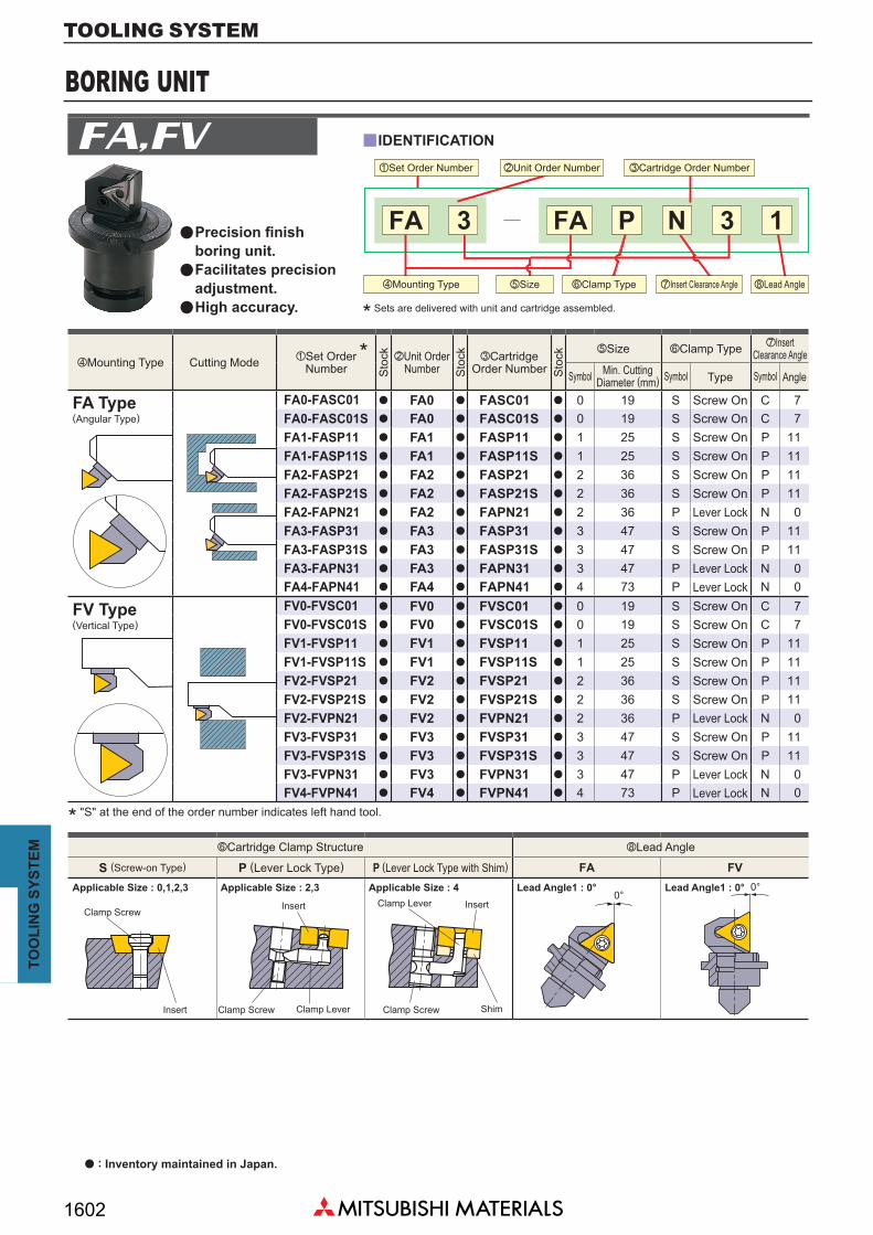
FA0-FASC01 a FA0 a FASC01 a 0 19 S C 7FA0-FASC01S a FA0 a FASC01S a 0 19 S C 7FA1-FASP11 a FA1 a FASP11 a 1 25 S P 11FA1-FASP11S a FA1 a FASP11S a 1 25 S P 11FA2-FASP21 a FA2 a FASP21 a 2 36 S P 11FA2-FASP21S a FA2 a FASP21S a 2 36 S P 11FA2-FAPN21 a FA2 a FAPN21 a 2 36 P N 0FA3-FASP31 a FA3 a FASP31 a 3 47 S P 11FA3-FASP31S a FA3 a FASP31S a 3 47 S P 11FA3-FAPN31 a FA3 a FAPN31 a 3 47 P N 0FA4-FAPN41 a FA4 a FAPN41 a 4 73 P N 0FV0-FVSC01 a FV0 a FVSC01 a 0 19 S C 7FV0-FVSC01S a FV0 a FVSC01S a 0 19 S C 7FV1-FVSP11 a FV1 a FVSP11 a 1 25 S P 11FV1-FVSP11S a FV1 a FVSP11S a 1 25 S P 11FV2-FVSP21 a FV2 a FVSP21 a 2 36 S P 11FV2-FVSP21S a FV2 a FVSP21S a 2 36 S P 11FV2-FVPN21 a FV2 a FVPN21 a 2 36 P N 0FV3-FVSP31 a FV3 a FVSP31 a 3 47 S P 11FV3-FVSP31S a FV3 a FVSP31S a 3 47 S P 11FV3-FVPN31 a FV3 a FVPN31 a 3 47 P N 0FV4-FVPN41 a FV4 a FVPN41 a 4 73 P N 0
FA FV
13P NFA3FA
0°0°
Precision finish boring unit.Facilitates precision adjustment.High accuracy.
IDENTIFICATION
zSet Order Number
a
a
a
vMounting Type bSize nClamp Type ,Lead AnglemInsert Clearance Angle
xUnit Order Number cCartridge Order Number
* Sets are delivered with unit and cartridge assembled.
vMounting Type zSet OrderNumber
xUnit OrderNumber
cCartridgeOrder Number
mInsertClearance AnglebSize nClamp Type
Cutting Mode *S
tock
Sto
ck
Sto
ck
Symbol Symbol Symbol AngleTypeMin. CuttingDiameter (mm)
Screw OnScrew OnScrew OnScrew OnScrew OnScrew OnLever LockScrew OnScrew OnLever LockLever LockScrew OnScrew OnScrew OnScrew OnScrew OnScrew OnLever LockScrew OnScrew On
Lever Lock
FA Type
FV Type
(Angular Type)
(Vertical Type)
* "S" at the end of the order number indicates left hand tool.
Applicable Size : 0,1,2,3 Applicable Size : 2,3 Applicable Size : 4 Lead Angle1 : 0° Lead Angle1 : 0°
Clamp ScrewInsert Clamp Lever Insert
Clamp Screw ShimClamp Screw Clamp LeverInsert
nCartridge Clamp Structure ,Lead Angle
S (Screw-on Type) P (Lever Lock Type) P (Lever Lock Type with Shim)
a : Inventory maintained in Japan.
Lever Lock

BORING UNIT
TOOLINGSY
STEM
TOOLING SYSTEM
1603
FA0 HSC02006 S1 HKY15RFV0 HSC02006 S1 HKY15RFA1 HSC02506 HY-A1 HKY20RFV1 HSC02506 HY-V1 HKY20RFA2 HSC03010 HY2 HKY20R,HKY25RFV2 HSC03010 HY2 HS-N2,HKY25RFA3 HSC04012 HY3 HKY20R,HKY30RFV3 HSC04012 HY3 HKY20R,HKY30RFA4 HSC05016 HY4 HKY30R,HKY40RFV4 HSC05016 HY4 HKY30R,HKY40R
DialLeaf Spring
Washer
Cartridge
BushWasher Screw
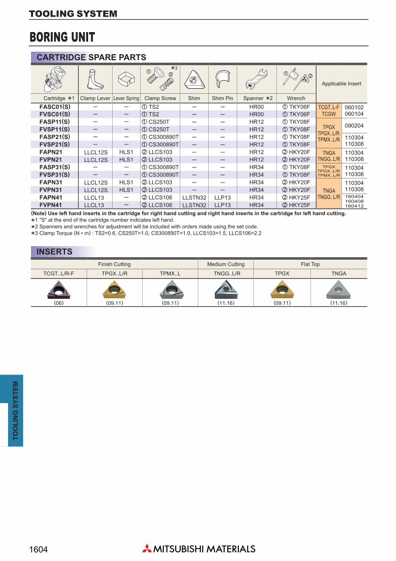
BORING UNIT SPARE PARTS
The parts above are not sold separately as accuracy can only be guaranteed by having the complete set. Please contact us for questions about parts replacement.
UnitOrder Number
Washer Screw Unit Screw Wrench Bush Washer Leaf Spring
BORING UNIT
TOOLINGSY
STEM
TOOLING SYSTEM
1604
TCGT..L/R-F TPGX..L/R TPMX..L TNGG..L/R TPGX TNGA
(06) (09,11) (09,11) (11,16) (09,11) (11,16)
FASC01(S) ─ ─ z TS2 ─ ─ HR00 z TKY06F TCGT..L-FTCGW
060102060104FVSC01(S) ─ ─ z TS2 ─ ─ HR00 z TKY06F
FASP11(S) ─ ─ z CS250T ─ ─ HR12 z TKY08FTPGX
TPGX..L/RTPMX..L/R
090204FVSP11(S) ─ ─ z CS250T ─ ─ HR12 z TKY08FFASP21(S) ─ ─ z CS300890T ─ ─ HR12 z TKY08F 110304
110308FVSP21(S) ─ ─ z CS300890T ─ ─ HR12 z TKY08FFAPN21 LLCL12S HLS1 x LLCS103 ─ ─ HR12 x HKY20F TNGA
TNGG..L/R110304110308FVPN21 LLCL12S HLS1 x LLCS103 ─ ─ HR12 x HKY20F
FASP31(S) ─ ─ z CS300890T ─ ─ HR34 z TKY08F TPGXTPGX..L/RTPMX..L/R
110304110308FVSP31(S) ─ ─ z CS300890T ─ ─ HR34 z TKY08F
FAPN31 LLCL12S HLS1 x LLCS103 ─ ─ HR34 x HKY20FTNGA
TNGG..L/R
110304110308FVPN31 LLCL12S HLS1 x LLCS103 ─ ─ HR34 x HKY20F
FAPN41 LLCL13 ─ x LLCS106 LLSTN32 LLP13 HR34 x HKY25F 160404160408160412FVPN41 LLCL13 ─ x LLCS106 LLSTN32 LLP13 HR34 x HKY25F
z zx x
INSERTS
CARTRIDGE SPARE PARTS
*1 *2
*3
Applicable Insert
Cartridge Clamp Lever Lever Spring Clamp Screw Shim Shim Pin Spanner Wrench
(Note) Use left hand inserts in the cartridge for right hand cutting and right hand inserts in the cartridge for left hand cutting.
*1 "S" at the end of the cartridge number indicates left hand.
*2 Spanners and wrenches for adjustment will be included with orders made using the set code.
*3 Clamp Torque (N • m) : TS2=0.6, CS250T=1.0, CS300890T=1.0, LLCS103=1.5, LLCS106=2.2
Finish Cutting Medium Cutting Flat Top

BORING UNIT
TOOLINGSY
STEM
TOOLING SYSTEM
1605
a
a
RE DMIN LDRED L21 S16 S17 L23 D15 DCON S12 S13 S18 Z X Y G IBD
S14 S15
FA0-FASC01(S) 0.2 19 0.32 0.16 9.0 19.9 0.30 0.12 1.5 11.11 15.06 2.7 8.2 1.11 1.2 6.4 6.5 1.0 6.8 DC-20.4 19 0.32 0.16 8.8 19.7 0.30 0.12 1.6 11.11 15.06 2.7 8.2 1.11 1.2 6.4 6.4 1.0 6.8 DC-2
FA1-FASP11(S) 0.4 25 0.5 0.3 11.7 23.9 0.38 0.23 0.8 15.08 19.05 3.2 9.0 0.46 1.0 7.6 9.1 0.9 8.4 DC-2
FA2-FASP21(S) 0.4 36 0.7 0.4 14.9 33.4 0.53 0.30 1.1 19.05 24.58 4.0 14.5 0.7 1.2 9.7 11.5 0.8 11.1 DC-20.8 36 0.7 0.4 14.5 33.0 0.53 0.30 1.3 19.05 24.58 4.0 14.5 0.7 1.2 9.7 11.2 0.8 11.1 DC-2
FA2-FAPN21 0.4 36 0.7 0.4 14.9 33.4 0.53 0.30 1.1 19.05 24.58 4.0 14.5 0.7 2.75 9.7 11.5 0.8 11.1 DC-20.8 36 0.7 0.4 14.5 33.0 0.53 0.30 1.3 19.05 24.58 4.0 14.5 0.7 2.75 9.7 11.2 0.8 11.1 DC-2
FA3-FASP31(S) 0.4 47 1.0 0.6 18.35 42.85 0.75 0.45 0.9 22.225 31.75 4.8 19.7 0.54 1.9 11.7 14.4 1.2 13.1 DC-30.8 47 1.0 0.6 17.95 42.45 0.75 0.45 1.1 22.225 31.75 4.8 19.7 0.54 1.9 11.7 14.1 1.2 13.1 DC-3
FA3-FAPN31 0.4 47 1.0 0.6 18.35 42.85 0.75 0.45 0.9 22.225 31.75 4.8 19.7 0.54 3.21 11.7 14.4 1.2 13.1 DC-30.8 47 1.0 0.6 17.95 42.45 0.75 0.45 1.1 22.225 31.75 4.8 19.7 0.54 3.21 11.7 14.1 1.2 13.1 DC-3
FA4-FAPN410.4 73 1.5 0.7 28.0 65.4 1.13 0.53 1.3 31.75 46.02 6.4 31.0 0.86 5.2 17.7 21.9 1.3 20.5 DC-30.8 73 1.5 0.7 27.6 65.0 1.13 0.53 1.5 31.75 46.02 6.4 31.0 0.86 5.2 17.7 21.6 1.3 20.5 DC-31.2 73 1.5 0.7 27.2 64.6 1.13 0.53 1.7 31.75 46.02 6.4 31.0 0.86 5.2 17.7 21.3 1.3 20.5 DC-3
RE DMIN LDRED L21 L23 D15 DCON S12 S13 Z X Y BD
S14 S15
FV0-FVSC01(S) 0.2 19 0.4 0.2 7.6 18.5 2.6 11.11 15.06 2.7 8.2 1.2 2.6 7.6 DC-20.4 19 0.4 0.2 7.4 18.3 2.6 11.11 15.06 2.7 8.2 1.2 2.6 7.4 DC-2
FV1-FVSP11(S) 0.4 25 0.7 0.3 10.8 23.0 3.6 15.08 20.62 3.2 9.0 1.0 3.6 10.8 DC-2
FV2-FVSP21(S) 0.4 36 0.8 0.6 13.8 32.3 4.0 19.05 24.58 4.0 14.5 1.2 4.0 13.8 DC-20.8 36 0.8 0.6 13.5 32.0 4.0 19.05 24.58 4.0 14.5 1.2 4.0 13.5 DC-2
FV2-FVPN21 0.4 36 0.8 0.6 13.8 32.3 4.0 19.05 24.58 4.0 14.5 2.1 4.0 13.8 DC-20.8 36 0.8 0.6 13.5 32.0 4.0 19.05 24.58 4.0 14.5 2.1 4.0 13.5 DC-2
FV3-FVSP31(S) 0.4 47 1.3 0.7 16.7 41.2 4.8 22.225 31.75 4.8 19.7 1.9 4.8 16.7 DC-30.8 47 1.3 0.7 16.4 40.9 4.8 22.225 31.75 4.8 19.7 1.9 4.8 16.4 DC-3
FV3-FVPN31 0.4 47 1.3 0.7 16.7 41.2 4.8 22.225 31.75 4.8 19.7 3.21 4.8 16.7 DC-30.8 47 1.3 0.7 16.4 40.9 4.8 22.225 31.75 4.8 19.7 3.21 4.8 16.4 DC-3
FV4-FVPN410.4 73 1.8 1.0 25.0 62.4 7.1 31.75 46.02 6.4 31.0 5.2 7.1 25.0 DC-30.8 73 1.8 1.0 24.7 62.1 7.1 31.75 46.02 6.4 31.0 5.2 7.1 24.7 DC-31.2 73 1.8 1.0 24.4 61.8 7.1 31.75 46.02 6.4 31.0 5.2 7.1 24.4 DC-3
X I
X
G
YY
RE
S17
S20
S19
S19= (0.25DC2-Z2)-Y
0.25DC2-Z2-Y
0.25DC2-Z2-(Y+0.6 x I)S20=
S20=
S16
S18
S14
S15
DM
INS1
5
DM
IN
L23L23
D15DCON
L21
LDRED
S12
S13
RE
53°08'
D15DCON
S13
LDRE
DS1
2
S20
REL23
L23
L21
S14
BD
BD
Z
Z
MAIN DIMENSIONSFA TYPE (ANGULAR TYPE)
FV TYPE (VERTICAL TYPE)
Set Order Number
Set Order Number
Adjustment
Adjustment
Max.
Max.
Unit Center Line
Unit Center Line
Cutting EdgeMovement A
djus
tmen
tA
djus
tmen
t
( Cutt
ing D
iamete
r)D
C
Unit : mm
Unit : mm
Clockwise (right hand) tool shown.Minimum cutting diameters (DMIN) correspond to RE0.2 (0 type) and RE0.4 (1─4 type).
Clockwise (right hand) tool shown.Minimum cutting diameters (DMIN) correspond to RE0.2 (0 type) and RE0.4 (1─4 type).
* "S" at the end of the order number indicates left hand tool.
*
( Cutt
ing D
iamete
r)D
C
*

MI TYPE BORING BARS
TOOLINGSY
STEM
TOOLING SYSTEM
1606
S
R
08 810 1012 1216 16
1 0°3 30°4 45°6 90°
z x c v b
y
SBR1
─
SBR6
08 CS200T ─ TKY06F
10 CS250T ─ TKY08F
12 CS300890T KS1S TKY08F
16 CS300890T KS2S TKY08F
H B LF LDRED ASP HF WF RE
SBR108 a TPGXTPGX...LTPMX...L
0802pp 7 8 35 9 ─ 7 3.5 0.4
SBR110 a 0902pp 9 10 50 11 ─ 8 4.5 0.4
SBR112 a 1103pp 10 12 60 12 7 10 5.0 0.4
SBR308 a TPGXTPGX...LTPMX...L
0802pp 7 8 35 10 ─ 7 0.7 0.4
SBR310 a 0902pp 9 10 50 12 ─ 8 1.0 0.4
SBR312 a 1103pp 10 12 60 13 7 10 1.0 0.4
SBR408 a
TPGXTPGX...LTPMX...L
0802pp 7 8 35 10 ─ 7 0.5 0.4
SBR410 a 0902pp 9 10 50 12 ─ 8 1.0 0.4
SBR412 a 1103pp 10 12 60 13 7 10 1.0 0.4
SBR416 a 1103pp 14 16 80 13 9 14 0 0.8
SBR608 a TPGXTPGX...LTPMX...L
0802pp 7 8 35 8.5 ─ 7 ─ 0.4
SBR610 a 0902pp 8 10 50 10 ─ 8 ─ 0.4
SBR612 a 1103pp 10 12 60 11 7 10 ─ 0.4
S B R 1 08
zx
WF
WF
WF
RE
RE
RE
RE
LDRED
LDRED
LDRED
LDRED
ASP
ASP
ASP
ASP
LF
LF
LF
LF
LF
LF
LF
LF
HF
HF
HF
HF
6°
6°
6°
5°
30°
45°
6°
5°
5°
5°
BB
BB
H
H
H
H
WF
WF
a : Inventory maintained in Japan.
IDENTIFICATION
zClamp Type
cShank Shape
bShank Size (mm)vLead AnglexBoring Bar NameScrew On Type
Round Shank
STANDARD HOLDER
SPARE PARTS
(Note) When using an insert with a breaker, please use a left hand insert.
* Clamp Torque (N • m) : CS200T=0.6, CS250T=1.0, CS300890T=1.0
Order Number
zClamp Screw xPre-Set Screw Wrench
Geometry Order NumberStock
* Insert NumberDimensions (mm)
ForClockwise
SBR1
SBR3
SBR4
SBR6
Insert

MI TYPE BORING BARS
TOOLINGSY
STEM
TOOLING SYSTEM
1607
14
Memo

CLASSIFICATION OF QUICK CHANGE / MODULAR TOOLING SYSTEM
TOOLINGSY
STEM
TOOLING SYSTEM
1608
QB2000 • QB3000 ABS License KOMET
HSKQB4000
R
Mitsubishi's quick change system is a must for improving efficiency in mass production lines.Shorten tool change times and increase machine efficiency.Reduce tool weight. Thus, tool change is safer and easier.Improve cutting edge accuracy.
QF1000 (Two Piece)
QC TYPE ADAPTERFOR PIN MILLING CUTTER
Face Mill and Pin Milling CutterQS2000 (Arbor for Side Cutter)
QF2000 (Small Diameter) QF2000 (Large Diameter)
Bor
ing
Tool
Con
nect
ing
Syst
em
MITSUBISHI'sQUICK CHANGE
SYSTEM
Special Tooling
SPQH (Spring) SPQS (Spring+Oil pressure)
Setting Fixture Setting Gauge
a
a
a

FACE MILL
TOOLINGSY
STEM
TOOLING SYSTEM
1609
a
a
a a
y
y
y
QF2000 (SINGLE BOLT MOUNTING TYPE)One Piece Type ( <&160)
Two Piece Type ( >&200)
One Piece Type (O Type &200) Two Piece Type (T Type >&250)
Machine Spindle
Adapter
Yellow Mark
Clamp Bolt
Clamp Bolt
Mounting Teeth
Cutter Body
Adapter
Setting Plate
Yellow Mark
FEATURES
FEATURES
FEATURES
1. Simply turning a clamp bolt fixed to the adapter a few times enables cutter exchange.
2. The cutter needs to be turned 90° before removal. This prevents the cutter from falling free.
3. Applicable to both face milling and boring tools.4. Cutter exchange time is less than 1 min.
1. Internal diameter of the cutter body has 4─6 mounting teeth. The adapter has the same mounting teeth and a single clamp bolt for installation.
2. The cutter needs to be turned 15° before removal. This prevents the cutter from falling free.
3. Cutter exchange time is less than 1 min.
1. Gourd shaped hole type is employed. Turning 4─6 bolts enables cutter exchange.2. The cutter needs to be turned 15° before removal. This prevents the cutter from falling free.3. Cutters with >Ø250 are made up of 2 parts. Thus, weight at the time of installation is reduced and safety is improved.4. Standard adapters facilitate installation of cutters with the same diameter and different insert shapes.5. Cutter exchange time is less than 3─5 min.
Cut
ter B
ody
QF1000 (GOURD SHAPED HOLE TYPE)

FACE MILLING ADAPTER
TOOLINGSY
STEM
TOOLING SYSTEM
1610
a a
(kg)DF DCON_WS FLGT DCON_MS DBC M KWW L8 L24QFA08025BCR/L 80 70 25.4 25 25.4 45 M12 9.5 7 18.4 0.8QFA10025BDR/L 100 80 31.75 25 31.75 55 M16 12.7 8 23.2 1.2QFA12530BER/L 125 100 38.1 30 38.1 70 M20 15.9 10 28 2.1QFA16030BFR/L 160 125 50.8 30 50.8 85 M20 19 11 36 3.2
(kg)BD DCON LB DF No. d2 LS KWW L8 L24QFA08025N4R/L 80 70 25.4 25 70 40 44.45 93.4 16.1 16 22.5 1.4QFA10025N4R/L 100 80 31.75 25 80 40 44.45 93.4 16.1 16 22.5 1.7QFA12530N4R/L 125 100 38.1 30 100 40 44.45 93.4 16.1 16 22.5 2.7QFA16030N4R/L 160 125 50.8 30 125 40 44.45 93.4 16.1 16 22.5 3.8QFA08025N5R/L 80 70 25.4 25 100 50 69.85 126.8 25.7 19 35.3 3.2QFA10025N5R/L 100 80 31.75 25 100 50 69.85 126.8 25.7 19 35.3 3.4QFA12530N5R/L 125 100 38.1 30 100 50 69.85 126.8 25.7 19 35.3 4.0QFA16030N5R/L 160 125 50.8 30 125 50 69.85 126.8 25.7 19 35.3 5.1
DF
DF
DCON_MS
BD d2
DC
ON
KW
W
DBC
KWW
L24
DCON_WS
L8FL
GT
1513
45°
L8
13 LB L24
R7/5
LS
Q TYPE (SINGLE BOLT TYPE) &80─&160Standard Installed Condition
(Key
Groo
ve D
epth)
"M" Bolt Hole
Machine Spindle
Adapter
Cutter Body
Clamp Bolt
7/24 Taper No.
Unlock
Lock
Order Number
Order Number
Cutter Dimensions (mm)
Cutter Dimensions (mm)
Machine Dimensions (mm)
Machine Dimensions (mm)
Tool Weight
Tool Weight
Cutter Diameter(DC)
Cutter Diameter(DC)

FACE MILLING ADAPTER
TOOLINGSY
STEM
TOOLING SYSTEM
1611
a
a
a
a
(kg)DCON_WS DF DCON_MS DBC mQFB20035KR/L 200 125 190 47.625 ─ ─ 9QFB25035KR/L 250 175 240 47.625 ─ ─ 16QFB31535PR/L 315 240 305 47.625 177.8 88.9 28QFB35535PR/L 355 280 345 47.625 177.8 88.9 37QFB40035PR/L 400 325 390 47.625 177.8 88.9 49QFB50035PR/L 500 425 490 47.625 177.8 88.9 83
(kg)DCON_WS DBC DF LB N DCON_MS DBC_2
QFA25035K 250 110 155 230 45 4 47.625 ─ 9QFA31535P 315 175 220 295 50 6 47.625 177.8 16 QFA35535P 355 215 260 335 50 6 47.625 177.8 22QFA40035P 400 260 305 380 50 6 47.625 177.8 29
DF
DF
DCON_MS
DBC
DBC_2
DCON_MS
ø101.6
25.4
DCON_WS
ø101.6DBC
DCON_WS
mLB15
25.4
11
50.8
80±0.05
80±0
.05
35±0.01
35±0
.01
10
45°45°
Standard
Standard
Installed Condition
Installed Condition
Order Number
Order Number
Cutter Dimensions (mm)
Cutter Dimensions (mm)
Machine Dimensions (mm)
Machine Dimensions (mm)
Tool Weight
Tool Weight
Cutter Diameter(DC)
Cutter Diameter(DC)
Q TYPE (SINGLE BOLT TYPE) &200─&500
T TYPE (SIX BOLT TYPE) &250─&400
Bolt Hole for M16Bolt Hole for M20
Machine Spindle
Adapter
Cutter BodyClamp Bolt
Bolt for M16 (4 Piece)Bolt for M20 (4 Piece)
* Adapter is for both right and left hand tools.
Bolt for M20 x 50 (N Piece)(JIS B 1176)
Machine Spindle
Adapter
Cutter Body
Unlock
Lock
Unlock
Lock

SIDE CUTTER
TOOLINGSY
STEM
TOOLING SYSTEM
1612
a
a
a
y
y
QC TYPE ADAPTER FOR PIN MILLING CUTTER
QS2000 (INSTALLATION METHOD FOR SIDE CUTTER)
Cutter Body
Adapter Body
Appearance
FEATURES
FEATURES
1. Makes installation of Pin millng cutter easy, quick, and accurate.2. Clamping the entire periphery of the cutter body improves rigidity and lateral run-out of the cutting edges.3. Facilitates stable heavy cutting such as counter weight cutting and prevents sudden insert fracture.
1. Turning the bolt a few times turns nut 45° and enables installation and detachment of the cutter.2. Installation and detachment of the cutter is possible without taking the bolt and nut off the adapter.3. The cutter is a solid type. Thus, the rigidity is high.4. Cutter exchange time is less than 1 min.
Clamp Bolt
Side Cutter
AdapterNut

BORING TOOL
TOOLINGSY
STEM
TOOLING SYSTEM
1613
y
a
DCON_WS DCON_MS DF d3 DBC M LB d4
QB4350070 35 30 70 28 52 M8 22 8QB4350088 35 30 88 28 70 M8 22 8
QB4400098 40 30 98 34 80 M8 24 8
QB4400118 40 30 118 34 90 M10 24 10QB4500138 50 40 138 42 110 M12 30 12
45° M
2-M12
22°3
0'
0.5 0.5
d3
DC
ON
_ WS
d4
5 8
DC
ON
_ MS
DB
C
DF
LB 30 15
QB4000 TYPE (SIDE CLAMP TYPE)
Snap Ring
Clamp Washer
NutAdapter Body
Clamp Bolt
Spring
Steel Ball
O Ring
O Ring
FEATURES1. Tightening the clamp bolt (or clamp nut) draws the clamp washer in and securely holds the boring head.2. The clamp washer has mounting teeth at the end. Turning the clamp washer 45° enables installation and detachment of the boring head.3. Both 1/5 taper and cutter locating faces support the boring head. Thus, clamp rigidity and installation repeatability accuracy are high (2─3!m).4. A side clamp structure is employed. Thus, a spindle turning stopper is unnecessary. This structure prevents the boring head from falling free.5. Insert location close to the adapter body allows for convenient head exchange.6. Suitable for a wide range of boring, from small to large diameters.7. Head exchange time is less than 1 min.
Installation Standard
Drive Pin
ø8(H8) (Long Hole)
Taper 1/5
Order Number
ABS License KOMET
TOOLINGSY
STEM
TOOLING SYSTEM
1614
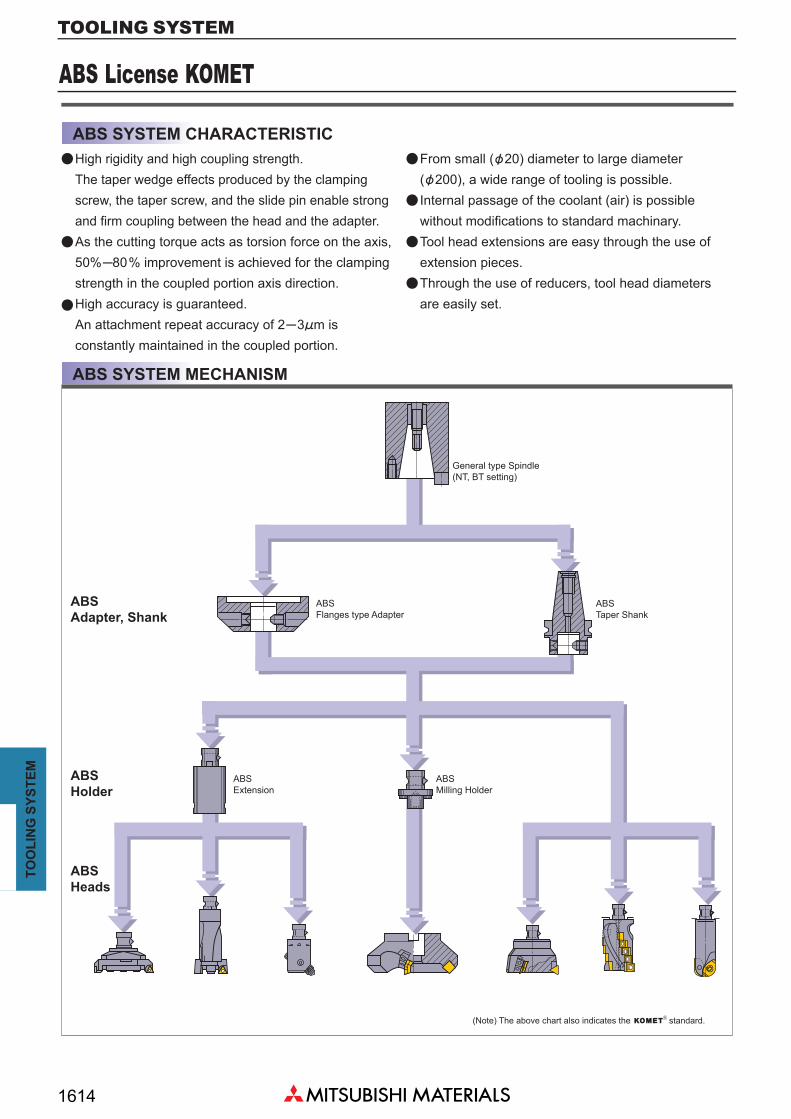
ABS SYSTEM CHARACTERISTIC
ABS SYSTEM MECHANISM
High rigidity and high coupling strength. The taper wedge effects produced by the clamping screw, the taper screw, and the slide pin enable strong and firm coupling between the head and the adapter.As the cutting torque acts as torsion force on the axis,50%─80% improvement is achieved for the clampingstrength in the coupled portion axis direction.High accuracy is guaranteed.An attachment repeat accuracy of 2─3!m is constantly maintained in the coupled portion.
From small (&20) diameter to large diameter (&200), a wide range of tooling is possible.Internal passage of the coolant (air) is possible without modifications to standard machinary.Tool head extensions are easy through the use of extension pieces.Through the use of reducers, tool head diameters are easily set.
General type Spindle (NT, BT setting)
ABS Taper Shank
ABS Flanges type Adapter
ABS Extension
ABS Milling Holder
(Note) The above chart also indicates the standard.
ABS Adapter, Shank
ABS Holder
ABS Heads
a a
a
a
a
a
a

ABS License KOMET
TOOLINGSY
STEM
TOOLING SYSTEM
1615
BD DCON CBDP L24 S1
ABS25W 25 13 22 13 8.3ABS32W 32 16 25 16 10.3ABS40W 40 20 30 18.5 11.3ABS50W 50 28 34 22 13.3ABS63W 63 34 41 28 17.4ABS80W 80 46 48 34 20.4ABS100W 100 56 58 40.5 24.4ABS125W 125 70 76 51 30.5
ABS25-FS-W a ABS25-F1 ABS25-F2ABS32-FS-W a ABS32-F1 ABS32-F2ABS40-FS-W a ABS40-F1 ABS40-F2ABS50-FS-W a ABS50-F1 ABS50-F2ABS63-FS-W a ABS63-F1 ABS63-F2ABS80-FS-W a ABS80-F1 ABS80-F2ABS100-FS-W a ABS100-F1 ABS100-F2ABS125-FS-W a ABS125-F1 ABS125-F2
a
F2
F1
FAFA
2xFA
CBDP
S1
DC
ON
BD
ABS SYSTEM SETTING STANDARDS Adapter Dimensions
Parts for Adapter
* An order of the above type of screw and pin needs to be included in the set. Please use a "Pack Order Number" for your order.
Clamp Screw
Taper Screw
a : Inventory maintained in Japan.
L24min.
Order NumberDimensions(mm)
Pack OrderNumber * S
tock Clamp Screw Taper Screw
ABS SYSTEM COMPONENT
Head Slide Pin
Position Pin
Taper Screw
Adapter
Clamp Screw
When the force F1 presses on the clamping screw, the slide pin moves in the radial direction and impinges on the taper screw, generation the reaction force F2. Since the centers of the clamping screw, the taper screw, and the slide pin are eccentric, a taper connection is made at sites separated by a 180° phase, with the clamping screw and the slide pin on the taper right impingement portion, and the slide pin and taper pin on the taper left impingement portion. The result is that, a vector analysis of those forces shows, as depicted in the diagram above, that the slides move in an identical direction, and the coupling force FA is doubled and transmitted accordingly. Further, cutting resistance generated during cutting becomes torsion stress and is transmitted accordingly. The forces F1 and F2 generated with the clamping screw and taper screw are expanded, and the coupling (jointing) force FA becomes as even greater force, and is generated accordingly.
* This system is licensed from of Germany.(JP Patent NO.1328669)

ABS License KOMET
TOOLINGSY
STEM
TOOLING SYSTEM
1616
BD DCON LS S1
ABS25M 25 13 20 8ABS32M 32 16 23 10ABS40M 40 20 26 11ABS50M 50 28 31 13ABS63M 63 34 38 17ABS80M 80 46 43 20ABS100M 100 56 55 24ABS125M 125 70 70 30
ABS25-ES-M a ABS25-E3 ABS25-E4 ABS25-E5ABS32-ES-M a ABS32-E3 ABS32-E4 ABS32-E5ABS40-ES-M a ABS40-E3 ABS40-E4 ABS40-E5ABS50-ES-M a ABS50-E3 ABS50-E4 ABS50-E5ABS63-ES-M a ABS63-E3 ABS63-E4 ABS63-E5ABS80-ES-M a ABS80-E3 ABS80-E4 ABS80-E5ABS100-ES-M a ABS100-E3 ABS100-E4 ABS100-E5ABS125-ES-M a ABS125-E3 ABS125-E4 ABS125-E5
ABS25-ES-M1 a ABS25-E3 ABS25-E4.1 ABS25-E5ABS32-ES-M1 a ABS32-E3 ABS32-E4.1 ABS32-E5ABS40-ES-M1 a ABS40-E3 ABS40-E4.1 ABS40-E5ABS50-ES-M1 a ABS50-E3 ABS50-E4.1 ABS50-E5ABS63-ES-M1 a ABS63-E3 ABS63-E4.1 ABS63-E5ABS80-ES-M1 a ABS80-E3 ABS80-E4.1 ABS80-E5ABS100-ES-M1 a ABS100-E3 ABS100-E4.1 ABS100-E5
ABS25-ES-M3 a ABS25-E3.2 ABS25-E4 ABS25-E6ABS32-ES-M3 a ABS32-E3.2 ABS32-E4 ABS32-E6ABS40-ES-M3 a ABS40-E3.2 ABS40-E4 ABS40-E6ABS50-ES-M3 a ABS50-E3.2 ABS50-E4 ABS50-E6ABS63-ES-M3 a ABS63-E3.2 ABS63-E4 ABS63-E6ABS80-ES-M3 a ABS80-E3.2 ABS80-E4 ABS80-E6ABS100-ES-M3 a ABS100-E3.2 ABS100-E4 ABS100-E6ABS125-ES-M3 a ABS125-E3.2 ABS125-E4 ABS125-E6
a
a
a
a
LSS1
DC
ON
BD
* This system is licensed from of Germany.(JP Patent NO.1328669)
a : Inventory maintained in Japan.
Head Dimensions
* An order of the above type of screw, pin and tube needs to be included in the set. Please use a "Pack Order Number" for your order.
Parts for Head
Parts for Head [For Fine Boring]
Parts for Head [For Coolant Hole Type]
Position Pin
Screw
Slide Pin
Tube
Screw
Slide Pin
Slide Pin
Position Pin
Position Pin
Order NumberDimensions(mm)
Pack OrderNumber * S
tock Slide Pin Position Pin Screw
Pack OrderNumber * S
tock Slide Pin Position Pin Screw
Pack OrderNumber * S
tock Slide Pin Position Pin Tube

ABS License KOMET
TOOLINGSY
STEM
TOOLING SYSTEM
1617
ABS25-ES-M4 a ABS25-E3.2 ABS25-E4.1 ABS25-E6ABS32-ES-M4 a ABS32-E3.2 ABS32-E4.1 ABS32-E6ABS40-ES-M4 a ABS40-E3.2 ABS40-E4.1 ABS40-E6ABS50-ES-M4 a ABS50-E3.2 ABS50-E4.1 ABS50-E6ABS63-ES-M4 a ABS63-E3.2 ABS63-E4.1 ABS63-E6ABS80-ES-M4 a ABS80-E3.2 ABS80-E4.1 ABS80-E6ABS100-ES-M4 a ABS100-E3.2 ABS100-E4.1 ABS100-E6
SBA25-ES-M a ABS25-E3 SBA25-E4 SBA25-E4.1 ABS25-E5SBA32-ES-M a ABS32-E3 SBA32-E4 SBA32-E4.1 ABS32-E5SBA40-ES-M a ABS40-E3 SBA40-E4 SBA40-E4.1 ABS40-E5SBA50-ES-M a ABS50-E3 SBA50-E4 SBA50-E4.1 ABS50-E5SBA63-ES-M a ABS63-E3 SBA63-E4 SBA63-E4.1 ABS63-E5SBA80-ES-M a ABS80-E3 SBA80-E4 SBA80-E4.1 ABS80-E5SBA100-ES-M a ABS100-E3 SBA100-E4 SBA100-E4.1 ABS100-E5SBA125-ES-M a ABS125-E3 SBA125-E4 SBA125-E4.1 ABS125-E5
SBA25-ES-M1 a ABS25-E3.2 SBA25-E4 SBA25-E4.1 ABS25-E6SBA32-ES-M1 a ABS32-E3.2 SBA32-E4 SBA32-E4.1 ABS32-E6SBA40-ES-M1 a ABS40-E3.2 SBA40-E4 SBA40-E4.1 ABS40-E6SBA50-ES-M1 a ABS50-E3.2 SBA50-E4 SBA50-E4.1 ABS50-E6SBA63-ES-M1 a ABS63-E3.2 SBA63-E4 SBA63-E4.1 ABS63-E6SBA80-ES-M1 a ABS80-E3.2 SBA80-E4 SBA80-E4.1 ABS80-E6SBA100-ES-M1 a ABS100-E3.2 SBA100-E4 SBA100-E4.1 ABS100-E6SBA125-ES-M1 a ABS125-E3.2 SBA125-E4 SBA125-E4.1 ABS125-E6
a
a
a
* An order of the above type of screw, pin and tube needs to be included in the set. Please use a "Pack Order Number" for your order.
Parts for Head [For Key Type with Coolant Hole]
Parts for Head [For Key Type]
Parts for Head [For Fine Boring with Coolant Hole]
Position Key
Key
Position Key
Key
Screw
Slide Pin
Slide Pin
Slide Pin
Position Pin
Tube
Tube
Pack OrderNumber * S
tock Slide Pin Position Pin Tube
Pack OrderNumber * S
tock Slide Pin Key Position Key Screw
Pack OrderNumber * S
tock Slide Pin Key Position Key Tube

HSK SYSTEM
TOOLINGSY
STEM
TOOLING SYSTEM
1618
FEATURES OF THE HSK SYSTEM
HSK CLAMPING METHOD
Suitable for high speed machining.When the taper hole is slightly seperated during high speed machining due to centrifugal force, the taper axis is continuously in contact with the taper hole because of elastic deformation. Thus, 2 face holding is maintained.Guaranteed high accuracy.Installation repeatability of 2!m is guaranteed.High rigidity.High rigidity in the radial and thrust direction due to the 2 face holding system.Easy installation.Detachable support structure ensures separation of the tool even when the tool has undergone thermal expansion.Coolant system selection.Center coolant and anglar flow coolant type.
Contact Faces Held Tightly
1/10 Taper Held Tightly
Coolant Hole
Clamp Bridge
Tapered Tool (Tool)
* HSK stands for Hole (Hollow) Schaft (axis) Kegel (taper) in German.
Clamp Screw Taper Hole (Spindle)
30°Conical Face
Temporary Clamp PositionThe spindle taper face and the tool taper face contact.
Permanent Clamp Position
a
a
Tapered Tool (Tool) Taper Hole (Spindle)
Tapered Tool (Tool)
Tapered Tool (Tool)
Taper Hole (Spindle)
Taper Hole (Spindle)
Held Tightly
Clearance
Draw In
The 30°conical face of the taper axis is pulled in the direction of the tapered hole to clamp.
Temporary clamp position has a clearance between the spindle and the tool contact faces.Taper clamping force increases as the diameter increases.
Hollow thin taper axis holds the taper faces and the contact faces tightly due to pressurized elastic deformation.
a
a
a
a
a
a
a
a
a

HSK SYSTEM
TOOLINGSY
STEM
TOOLING SYSTEM
1619
r
r
r r
r r
DCON LS
HSK-A32M 32 16
HSK-A40M 40 20
HSK-A50M 50 25
HSK-A63M 63 32
HSK-A80M 80 40
HSK-A100M 100 50
DCON LS
HSK-C32M 32 16
HSK-C40M 40 20
HSK-C50M 50 25
HSK-C63M 63 32
HSK-C80M 80 40
HSK-C100M 100 50
LS
LS
HSK SYSTEM FORMThere are various HSK types.Mitsubishi Materials produces A, B, C, and D types of taper axis (tool size) and C and D types (manual operation) of taper hole (spindle side).
r : Non stock, produced to order only.
Grip Groove for ATC
Coolant Pipe
Hole for ID Insert Drive Key
Dia
met
er D
CO
ND
iam
eter
DC
ON
Coolant Hole
Hole for Manual Wrench
Drive Key
Type Application Tapered Tool(Tool)
Tapered Hole(Spindle)
A Type Automatic tool change (ATC), center coolant (mainly milling tools)
B Type Automatic tool change (ATC), angular flow coolant (mainly turning tools)
C Type Manual tool change, center coolant (mainly milling tools)
D Type Manual tool change, angular flow coolant (mainly turing tools)
Order NumberDimensions (mm)
Order NumberDimensions (mm)
Aut
omat
ic T
ool C
hang
e
A Ty
pe (C
ente
r Coo
lant
Typ
e)
Mill
ing
Tool
Man
ual T
ool C
hang
e
C T
ype
(Cen
ter C
oola
nt T
ype)