general articles gasifier stoves – science, technology …
TRANSCRIPT

GENERAL ARTICLES
CURRENT SCIENCE, VOL. 98, NO. 5, 10 MARCH 2010 627
H. S. Mukunda, P. J. Paul and N. K. S. Rajan are in the Department ofAerospace Engineering, and S. Dasappa is in the Centre for SustainableTechnologies, Indian Institute of Science, Bangalore 560 012, India; Mahesh Yagnaraman and Mukund Deogaonkar are in First Energy Pri-vate Limited, Baner Road, Baner, Pune 411 045, India; D. Ravi Kumaris in Energy Division, GE Office, New Delhi 110 015, India. *For correspondence. (e-mail: [email protected])
Gasifier stoves – science, technology and field outreach H. S. Mukunda*, S. Dasappa, P. J. Paul, N. K. S. Rajan, Mahesh Yagnaraman, D. Ravi Kumar and Mukund Deogaonkar Development of a new class of single pan high efficiency, low emission stoves, named gasifier stoves, that promise constant power that can be controlled using any solid biomass fuel in the form of pellets is reported here. These stoves use battery-run fan-based air supply for gasification (pri-mary air) and for combustion (secondary air). Design with the correct secondary air flow ensures near-stoichiometric combustion that allows attainment of peak combustion temperatures with ac-companying high water boiling efficiencies (up to 50% for vessels of practical relevance) and very low emissions (of carbon monoxide, particulate matter and oxides of nitrogen). The use of high density agro-residue based pellets or coconut shell pieces ensures operational duration of about an hour or more at power levels of 3 kWth (~12 g/min). The principles involved and the optimization aspects of the design are outlined. The dependence of efficiency and emissions on the design parameters are described. The field imperatives that drive the choice of the rechargeable battery source and the fan are brought out. The implications of developments of Oorja-Plus and Oorja-Super stoves to the domestic cooking scenario of India are briefly discussed. The process development, testing and internal qualification tasks were undertaken by Indian Institute of Science. Product development and the fuel pellet production were dealt with by First Energy Private Ltd. Close interaction at several times during this period has helped progress the project from the laboratory to large scale commercial operation. At this time, over four hundred thousand stoves and 30 kilotonnes fuel have been sold in four states in India. Keywords: Biomass stove, domestic stove, gasifier stove. RESEARCH, development and dissemination on biomass-based domestic combustion devices otherwise termed cook stoves have a long history of over five decades. Many developments have occurred due to intuitive appro-aches to examine heat transfer aspects relegating the combustion issues to a peripheral state. A broad summary of the scientific work performed till mid-80s has been re-ported1. More than a hundred designs from all parts of the world have been documented and these are discussed in a website devoted to cook stoves (www.bioenergylists.org). Stoves are made of metal, mud, refractories of various qualities with and without chimney. Chimney-based stoves are considered superior to chimney-less stoves be-cause any emission is taken out of the kitchen thus pre-serving the indoor air quality. However, these emissions
create a load on the environment and has become a matter of serious concern in the last several years. Further, even the single pan stoves without chimney have air supply by free convection since electric supply was not to be found in most rural dwellings which is where these stoves were largely expected to be used. Most of these stoves had utilization efficiencies assessed by water boiling tests between 10% and 20% (see for instance, Bhattacharya et al.2,3) while one slightly complex design shows an effi-ciency of 40% at small power levels (see Mukunda et al.4 for details). It has been known that both kerosene and LPG stoves have efficiencies as high as 65% and 70%. The question as to what limits the efficiencies in biomass stoves in comparison to kerosene and LPG stoves had remained un-examined till Mukunda et al.4 studied this aspect experimentally. They specifically showed that the efficiency is directly related to the operation of the stove at near-stoichiometric conditions that lead to peak com-bustion temperature of the product gases; it is this temperature that influences the heat transferred to the vessel within the limited bottom area available. Hence, the stove operation can be expected to be the best when

GENERAL ARTICLES
CURRENT SCIENCE, VOL. 98, NO. 5, 10 MARCH 2010 628
the air-to-fuel ratio is maintained near stoichiometry, albiet on the lean side to ensure minimum CO emissions; limiting the emissions of NOx is taken care of naturally by the lower combustion temperatures of biomass-air sys-tem as thermal NOx is the predominant source. Limiting the velocities in the fuel residing zone will help limit the particulate carry over. The stove designs that have (i) free convection-based air ingestion and (ii) biomass loaded as and when it is thought fit into the hot combustion zone, will function with air-to-fuel ratios that can be very rich or very lean. The former condition leads to sooting and the latter to smoking. Also, parts of the fuel over the stove may still be cold leading to air flow out of the stove body without participating in the combustion while other areas are deprived of the needed air for combustion. Coupled to all these, the biomass may either be dry or very wet. The latter condition will lead to poor combustion with heavy smoking. Thus, improvement of biomass-based stove combustion involves biomass quality and combustion aerodynamics, a view that has not been adequately reflected either in the stove literature or in the develop-ment of improved cook stove initiatives in the past. Typical specifications of a domestic stove can be deri-ved from comparable stoves based on kerosene or LPG that have an input power level of about 2.0 kWth (~3 g/min of LPG). Accounting for efficiency differ-ences, the biomass stove input power level can be set at about 3 kWth (12 g/min of biomass). The stove must allow continuous operation and if not, must last the complete cooking duration that has been estimated as about one hour. One would expect to have clean combus-tion with minimal emissions. Minimizing emissions of CO and other unburnt products of combustion calls for maximizing the combustion efficiency, and minimizing CO2 emissions implies maximizing the utilization effi-ciency (or water boiling efficiency on vessels of practical relevance). One would desire a smooth start-up and some control on the power level. The life of the stove must be large, at least two to three years. In doing all these, the cost of the stove must be affordable. The work described here is arranged as follows: (i) principles of gasifier stove, (ii) free convection versus forced convection operation, (iii) gasifier stove versus in-situ combustion stove, (iv) fuel for the stove, (v) the stove, efficiency and emissions, (vi) power pack related aspects, (vii) stove performance evaluation by others, and (viii) comparison with other developments. The broad implications of these developments to the country and other countries that have similar require-ments or challenges are also brought out.
Principles of gasifier stove
Gasifiers are essentially devices that enable converting solid fuel to gaseous fuel by a thermochemical conver-
sion process. This process involves substoichiometric high temperature oxidation and reduction reactions between the solid fuel and an oxidant – air in the present case. This is arranged such that air and the gas passes through a fixed packed bed. The gasification knowhow has a long history; it be-came particularly important in the European scene during the World War II when fossil fuel availability was scarce. Research and development into gasification process came to a low after fossil fuel availability became normal and their prices low. The area has become active in the last 30 years particularly in oil-importing countries like India. Research relevant to the objectives of this article can be traced to rice hull gasification systems that used a vertical cylinder filled with rice hull and air drawn through the packed bed from the top. While these were first deve-loped in China as early as in 1967 (see Bhattacharya5), the scientific study was conducted by Kaupp6. In this reactor, shown on the left side of Figure 1, one can use biomass like wood chips, and pellets apart from ricehulls for which it was first conceived. If now the reactor is op-erated such that air flows from the bottom and the fuel surface at the top is lit, one would get combustible gases that will burn above the top surface with ambient air or with additional air supplied towards the top. Such a con-figuration, shown on the right side of Figure 1 termed reverse downdraft gasifier, constitutes the essence of a gasifier stove. An important consequence of this mode of operation is that the gas exiting from the top of the packed bed bears a fixed ratio to the amount of air intro-duced for gasification (primary air owing from the bot-tom). The reduction reactions following the oxidation limit the amount of fuel to be consumed due to the endo-thermic nature of these reactions. The interesting feature is that the relative amounts of fuel consumed and air introduced remain the same and increased amount of
Figure 1. a, Schematic view of a rice hull gasifier. Note that the air flows from the open top towards the bottom. b, Schematic representa-tion of a reverse downdraft gasifier stove where the gasification air flows from bottom to top.

GENERAL ARTICLES
CURRENT SCIENCE, VOL. 98, NO. 5, 10 MARCH 2010 629
solid is consumed when primary air flow rate increases. Thus, the power of the stove is proportional to the pri-mary air flow rate. The gases coming out of the bed will be at a temperature of 800–1100 K and will be composed of CO, H2, CH4, H2O (as gas), some higher hydrocarbons and N2. These gases are burnt to CO2 and H2O with a second stream of air which is introduced in the top region for this purpose. Based an early work of La-Fontaine and Reed7, Reed and co-workers developed a free convection-based gasi-fier stove8 and have subsequently discussed the develop-ment of forced convection-based gasifier stove9,10. The biomass is largely wood chips and the forced convection depended on a fan; it formed the basis of camp stove and this is indeed how it got marketed. While the broad prin-ciples were clear at this time, the aspects of process opti-mization and development of components needed to be addressed to deal with the affordability issue in emerging economies like India with fuels depending on agro-residues rather than wood chips. One of the key drivers for the development was the evolution of low cost storage battery based fan; the idea of building a domestic stove became meaningful when the fans for supplying air were being built in numbers for computer applications and at this stage, low power fans could be obtained or built at less than 5 USD per system including the electrics. Work at the IISc laboratory on gasification systems had begun in 1983 (ref. 11) and reached reasonable maturity by the end of nineties, and the work on the development of stoves of high efficiency began in 1999 with a study to determine the dependence of various parameters on water boiling efficiency and emissions with several agro-residues.
Free versus forced convection stoves
Nearly all the domestic cook stoves over the world are free convection driven. In several of these designs the free convective driving potential is so small that the smallest of ambient disturbances can affect the air flow through the stove. Even in better of these designs with a column of hot zone (due to the combustion chamber) that enables stabilize the flow through the stove, flow distur-bances caused by varying heat release across the section of the combustion chamber due to randomly located and moved-around pieces of ‘firewood’ leads to widely vary-ing air-to-fuel ratios locally. This kind of a variation re-duces the peak flame temperature most of the time and leads to emissions of CO, unburnt hydrocarbons (UHC) and particulates significantly. Even when better efficien-cies are obtained, the stove operation becomes rich and significant sooting will result. This is particularly because faster cooking is understood to be obtained at a larger fuel burn rate and this is achieved by introducing more fuel into the combustion space. Getting good emis-sion performance from such stoves is usually a difficult
task. Thus laboratory test results and operational data from realistic environment can be widely different. Much of the current debate with regard to the standards and pro-tocols for testing stoves arising from the fact that the laboratory tests are different from real experiments is due to this fundamental aspect of the free convection stove; by design, the efficiency as well as emissions are depend-ent on the user and the ways the stove-fuel combination is used. Free convective stoves were and even now, are con-sidered inevitable because of the (i) perception that such stoves provide the ‘choice’ and flexibility and allow the users to continue to use whatever non-processed raw biomass and/or wood they were using, (ii) use of any forced draft that requires electricity is seen as difficult and/or unavailable. The point (i) needs to be challenged given the variable and distinctly poorer performance on efficiencies and emissions that have been observed and recorded (to be brought out subsequently). As far as point (ii) is concerned, improvement in electricity, infrastruc-ture and technology of smaller fans and power sources have given the real option to provide forced convection in the stove designs to improve performance and reduce emissions. All these do not imply that the rural environ-ment enjoys the availability of electricity all the time; perhaps, they have it over few hours a day. Yet the fact that electricity is available over some period can be made use of for the use of electricity-enabled stove designs. Also, it is possible that nothing better than free convec-tion stove can be contemplated in regions deprived of electricity totally. This should not mean that other regions that have electricity support even over the part of day should be deprived of modern technology interventions.
In-situ combustion stove versus gasifier stove
Another stove design that has been revealed in recent times that has had a limited dissemination is an in-situ combustion stove. Such a stove is not different from a furnace in principle. One supplies enough air for combus-tion directly around the fuel zone so that some parts of the fuel will undergo volatilization and the volatiles will burn with the air around, other parts that have become char will also simultaneously be oxidized. In some stoves (like Priyagni in India) the air flow occurs through the grate and over it just from around a chamber (of short height) to complete the combustion process. While direct combustion systems are common at large power levels where fuel feeding can be automatic and combustion management is relatively easy, at small throughputs like in a domestic stove, fuel loading has to done at frequent intervals (typically every few minutes apart) manually to ensure complete combustion with smaller packets of fuel and this may be considered a burden on the user in com-parison to dealing with conventional stoves. The power variation with time is dependent on this attention. If per-chance, the amount loaded at one time is more than what

GENERAL ARTICLES
CURRENT SCIENCE, VOL. 98, NO. 5, 10 MARCH 2010 630
the system can carry, significant emissions will result. Here again it may turn out that a trained operator in a laboratory can get good emission performance, but users in the field may end up with poor emission performance. In comparison to the above mentioned designs, gasifier stoves with loaded fuel provide an alternative. Gasifier stove that has loaded fuel pellets/pieces can be conceived from the end user as a starting point. Starting with the amount of cooking energy needed to cook one meal, the design of the stove has been arrived at in combination with amount of fuel to be loaded in such a way that the operation is relatively foolproof. The stove operation is dependent on thermo-chemistry which modulates the gas production process. At any fixed power level, the gas composition and temperature remain steady and with appropriate secondary air flow, the flame will get main-tained at its peak temperature in a near-steady mode. However, when power variation is demanded, it takes a transition time (of about a few minutes) much unlike a gas stove since the thermal inertia in the hot fuel bed has to be overcome in the process of reaching a new steady state. This design while providing flame control to the users, also makes it less user-dependent for achieving desired efficiency and emissions, and it may be expected that field results would be close to those obtained at the laboratory.
Fuel for the stoves
Historically, biomass stoves imply ‘firewood’ stoves. It is generally thought that firewood of any size, shape should be acceptable; moisture in the firewood is known to be undesirable, but there is no rigour in ensuring dry bio-mass use in stoves. The national statistics on fuel use in cook stoves in rural and urban environments is presented in Table 1. This table is composed of the data provided by various workers12–15. The differences between various studies and the data of Table 1 can be expected to have inaccuracies up to 15%. Table 1. National fuel usage in rural and urban households and energy efficiency
Rural Urban Fuel used Unit fuel Unit energy Fuel type (mhh) (mhh) (mmt/yr) (t/yr/hh) (GJ/yr/hh)
Firewood 87 15 250 2.5 40.0 Agro-residue 20 2 120 5.5 77.0 Cowdung cake 20 2 95 4.3 55.0 Coal, coke 2 2 6 1.5 27.0 Kerosene 2 8 5 0.5 21.0 LPG 9 25 8 0.24 5.7 Others 1 2 – – Total 141 66 465a 3.2a,b 47a,b
aSolid bio-fuels only; bNational averages; hh, household; mhh, million household; mmt, million metric tonnes; yr, year; t, tonnes; GJ, Gega Joules.
The data in the table is revealing. While wood and agro-residues are both biomass, the amount of agro-residues used on a per household basis is nearly twice that of wood. While it is generally understood that wood use itself is inefficient, the degree of wastefulness of agro-residues is enormous, a fact about which there is little appreciation all-round. If developing improved cook stoves on firewood is considered important, it is far more important to develop stoves to burn agro-residues that are light and odd shaped to obtain high efficiency and reduce the emissions. The magnitude of the use of cowdung cake as a source for fuel is non-insignificant, but its use is about as energy-inefficient as agro-residues. However, the emissions from its use are significant and any improvement in the use of cowdung cake should address this aspect as well. Coal is used in a wasteful way largely because of ignition problem. Many of the stoves are lit in the open for the volatiles to escape (about 30% in comparison to biomass with 70% volatiles) until coal becomes virtually coke and its combustion becomes vigorous. China that has encouraged a large production of coal-powder based beehive briquettes has serious indoor air pollution problems related to this fact16. LPG and kerosene are more sought-after fuels and are in the upper region of the energy ladder. Hence, they turn out to be important as reference for performance com-parison. Kerosene is a fuel used to a larger extent by the urban poor with relatively small kitchens and cannot afford the costs of LPG for cooking. Both these have higher water boiling efficiency. Laboratory experiments have shown water boiling efficiencies of 70–75% for LPG stoves and 60–65% for kerosene stoves. Kerosene use as fuel on a per-household basis appears large whereas the usage of LPG seems not unreasonable (one 14 kg cylinder for three weeks for a family of five). The calorific values of biomass, kerosene and LPG are 16, 42 and 45 MJ/kg and on this basis, one would have expected kerosene usage to be about 30% higher than LPG allowing for differences in the utilization efficiency. Perhaps, the magnitude reported on kerosene use for cooking may be inaccurate as it is generally known that significant amount of kerosene bought under public distribution scheme at subsidized prices is sold away as either cooking fuel or fuel for adulteration with gasoline at higher prices. The calorific value ratio coupled with efficiency differ-ences allows speculation on how much of solid biomass is needed for domestic cooking on a national scale. The equivalent of 0.24 tonnes/yr/hh of LPG translates to bio-mass of 1.20 t/yr/hh [0.24 × (45/16) × (70/40)]. Achiev-ing this implies that one would aim at a total solid biofuel use for cooking of 253 mmt/yr as against the current estimate of 465 mmt/yr. The magnitude of the task can be understood if we note the current efficiencies of firewood stoves as 20%, of agro-residue based stoves (or their use in the same firewood stoves) at 10% and cowdung cakes

GENERAL ARTICLES
CURRENT SCIENCE, VOL. 98, NO. 5, 10 MARCH 2010 631
Table 2. Average food consumption, energy intake, fuel required for cooking and cooking energy
cpm cpd Fuel/food Fuel/person/day Food cals Calories Food item (kg/p/m) (g/p/d) (g/g) (g/p/d) (cals/g) (cals/d)
Rice 7.2 240.0 0.23 55.2 1.5 360 Wheat 4.4 146.7 0.23 33.7 3.0 440 Other cereals 1.3 43.3 0.23 10.0 1.0 43 Pulses 0.9 30.0 0.15 4.5 0.7 1 Dairy 4.2 140.0 0.04 5.6 1.0 140 Edible oil 0.5 16.7 0.06 1.0 9.0 150 Meat/fish/egg 1.6 53.3 0.30 16.0 4.0 213 Veg/fruit 10.2 340.0 0.03 10.2 0.4 136 Sugar/spices 1.5 50.0 3.5 175 Processed food 1.6 53.3 3.0 160 Beverages 2.3 76.7 3.0 230
Total 136.2 2048
cpm, Consumption per month; cpd, consumption per day; m, month; p, person; d, day. as 12%. Enhancing the efficiency of the use of agro-residue based fuels and cowdung cakes must occupy the highest attention, next to which is firewood. Cowdung can perhaps be integrated into the strategy for better fuel making without any special stove design for cowdung cakes; fuels based on agro-residues and cowdung should be dealt with as a separate development task. Lastly, it is noted from Table 1 that the average energy per year per person is estimated at 5–10 GJ (ref. 12). The present estimate of 8.9 GJ/person/year (the average household in rural India is 5.3 as per the recent census documents) falls within the range obtained earlier. One can get an assessment of the cooking energy needs by determining the amount of food cooked per day, assessing how much of solid biofuel is needed to achieve this. Table 2 gives data of the average monthly consump-tion of food items in India drawn from a recent study17. The amount of fuel required for cooking these items (excepting for meat/fish/egg item) as determined from actual cooking experiments4 in a biomass stove with 40% water boiling efficiency are also shown in Table 2. Using these data, the amount of fuel required to cook food for one person for a day is obtained (food/p/d). The last two columns indicate the calories in each of the food items and the calorie intake in the food per day. As can be seen from the table, the total fuel per person per day is 136.2 g and for a household this translates to 722 g of biomass fuel/day which implies 0.26 t/yr/hh. This will perhaps be an absolute lower bound of the possibility. The differ-ence between this value and the one deduced earlier –1.2 t/yr/hh is not small and may be related to the differ-ence in food intake between LPG users and others and needs reconciliation. At this point, it is appropriate to conclude that a more realistic target would be 1.2 t/yr/hh of biomass.
Issues with agro-residues and cowdung
Most agro-residues are characterized by seasonal avail-ability and low intrinsic as well as bulk density. Typically,
intrinsic density varies from 50 to 200 kg/m3 whereas bulk density would be 50–70% of this value. There is also substantial moisture (up to 50%) at the time the material is harvested. The fact that densities are low per-mits loss of moisture even in open air storage, the extent of loss depending on the ambient conditions. Transporta-tion and combustion are affected by these aspects. Draw-ing from the practice of firewood transportation, it is understood to be economical to transport about 10 t of firewood over hundreds of kilometers, shorter the dis-tance the better. A truck carrying 10 t of firewood whose typical density is upwards of 500 kg/m3 can carry less than a few tonnes of agro-residues economically. The region to be covered to maintain a continuous supply of a variety of these residues becomes large, many times larger than economics can support. Hence, densification is an important element in the process. A question then arises – is it not good enough to densify the material to as much as firewood (implying about 500 kg/m3)? The answer to this question comes from the stove that uses this material. Approaching high efficiencies of a LPG stove demands that the combustion volume be brought down to as low a value as possible. This can be obtained by increasing the density of the fuel. Also in a stove with a fixed storage volume for the fuel like the one consi-dered here, increasing the density helps in reducing the overall chamber volume that would have benefits of lower inert material content and associated heat loss. A question that next arises is the level to which the material must be densified. Here, practice in industries suggests that binderless briquetting achieves a density of 1000–1100 kg/m3. This would form an upper limit to which the material must be densified. Since the requirement in stoves will turn out to be small-sized pieces, one needs to produce pellets, typically of 10–12 mm diameter and up to 40 mm long to obtain good packing density. Producing pellets of this size at large throughputs in an economical way has many challenges in the process as well plant throughput sizing both of which have not been addressed adequately in this country, yet. Pellet making and bri-

GENERAL ARTICLES
CURRENT SCIENCE, VOL. 98, NO. 5, 10 MARCH 2010 632
quetting have different process fundamentals. Briquetting process uses very high pressures, of the order of 1200 atms to generate heat due to friction between the material and the die wall to raise the temperature up to 350°C to enable lignin to be released. This lignin acts as a powerful binder. Pelleting process uses moisture or steam in extruding the material through a small die; the temperatures achieved are not high, typically, around 100°C to 120°C. Under these conditions, the crude pro-tein present in the biomass is softened and helps in the binding process. The densities achieved are usually lower than in binderless briquetting and are typically about 600–800 kg/m3. The presence of crude protein is impor-tant and hence any kind of ingredients having some amount would aid in the process and enhancing the throughput of the system. Cowdung is a major cooking fuel in north India, perhaps in conjunction with agro-residues or firewood. Huge mounds of dry cowdung are set around houses to enable peal-off and use in the stoves. Cowdung itself has com-ponents that could help pelleting in both the intrinsic feed material (to the bovines) and due to what happens in the rumen of the bovines. This is an important task for the future. Typical agro-fuels used currently are bagasse and groundnut husk as primary fuels along with tamarind husk, deoiled ricebran, sawdust and other seasonally available wastes as secondary ingredients. The team at FEPL has had wide experience in using fodder pellet making machines. The fuel pellet throughput comes down to 50–60% of the fodder pellet throughput with increased maintenance. After much consideration, two pellet machines were obtained from Europe and they have been set up, one of 20 t/d Dharwad (Karnataka) and another of 50 t/d at Islampur (Maharashtra). These installations are producing pellets and with other procurements a total of 1600 t/month is being supplied into the market.
The stove, efficiency and emissions
The development was carried out over a period with different fuels, different sized combustion chambers and designs of air supply to establish the performance as a function of various parameters on efficiency. Actual emission measurements were undertaken in the last stage as it was clear that obtaining the highest combustion effi-ciency (and accompanying utilization efficiency) with relatively short visible flame heights was needed to be achieved first; it was inferred that this would also imply reducing the emissions. The amount of secondary air was varied to obtain a short visible flame. This meant that the ambient air demanded for combustion was minimal. The relevant dimensions of the stoves built for this purpose and their performance are shown in Table 3. The experiments were made with the stove and vessel with water kept on a balance. The mass of the system was continuously measured along with the temperature of the water after it was vigorously stirred once in a while. Fig-ure 2 shows the plot of the mass of the fuel burnt with time. As can be noticed, there are two distinct phases of heat release. The first part is due to flaming and the second part due to char combustion. The power output during the second phase is about a fourth of the power in the first phase. The slope of the mass versus time plot gives the mass loss rate that is the same as burn rate; this quantity multiplied by the calorific value will give the power of stove. Three cooking vessels were used for determination of the thermal utilization efficiency. The consideration behind this choice is that small families may use smaller vessels and larger families, larger vessels. It would be valuable to determine the efficiency with vessel size. It can be expected that larger diameter vessels extract more heat compared to smaller vessels and hence designs that allow greater heat extraction from the same stove would
Table 3. Initial experiments – stove geometry, fuels and performance
ρbulk Moisture Ash Biomass Burn time+ Power* ηwb Biomass (kg/m3) (%) (%) loaded (g) (min) (kWth) (%)
Stove diameter = 100 mm, chamber volume = 0.6 liter, vessel = 10 liter WC 220 10 0.8 130 14 + 5 2.3 49.3 RHB + WC 500 7 18.3 250 + 50 27 + 10 1.9 49.3 CS + WC 430 9 0.6 230 + 30 30 + 10 2.2 53.3 MP + WC 366 12 11.3 225 + 30 18 + 7 2.5 49.1 Stove diameter = 125 mm, chamber volume = 0.9 liter, vessel = 10 liter WC 200 10 0.8 170 30 + 8 5.0 48.0 MP + WC 366 14 10.0 325 + 25 40 + 11 3.5 51.5
+The split-up is between flaming and char combustion times; *Power over the flaming time. WC, Wood chips; RHB, rice husk briquette pieces; CS, coconut shell pieces; MP, Marigold waste pellets.
GENERAL ARTICLES
CURRENT SCIENCE, VOL. 98, NO. 5, 10 MARCH 2010 633
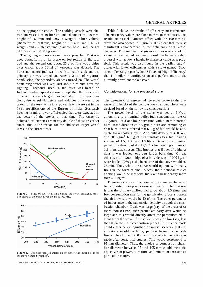
be the appropriate choice. The cooking vessels were alu-minium vessels of 10 liter volume (diameter of 320 mm, height of 160 mm and 0.96 kg weight), 6 liter volume (diameter of 260 mm, height of 130 mm and 0.61 kg weight) and 2.5 liter volume (diameter of 205 mm, height of 105 mm and 0.34 kg weight). The lighting up process used two approaches. First one used about 15 ml of kerosene on top region of the fuel bed and the second one about 25 g of fine wood chips over which about 10 ml of kerosene was doused. The kerosene soaked fuel was lit with a match stick and the primary air was turned on. After a 2 min of vigorous combustion, the secondary air was turned on. The vessel containing water was kept just about a minute after the lighting. Procedure used in the tests was based on Indian standard specifications except that the tests were done with vessels larger than indicated in the specifica-tions; the vessel diameters and volumes of water to be taken for the tests at various power levels were set in the 1991 specifications of the Bureau of Indian Standards keeping in mind lower efficiencies that were expected in the better of the stoves at that time. The currently achieved efficiencies are nearly double of those in earlier times; this is the reason for the choice of larger vessel sizes in the current tests.
Figure 2. Mass of fuel with time during the stove efficiency tests. The slope of the curve gives the mass loss rate.
Figure 3. Effect of vessel diameter on efficiency, the lower plot is for the stove named Swosthee4.
Table 3 shows the results of efficiency measurements. The efficiency values are close to 50% in most cases. The results on vessel diameter effect with the 100 mm dia stove are also shown in Figure 3. It is clear that there is significant enhancement in the efficiency with vessel diameter. This implies that given an option of a cooking vessel with a desired volume, it would be better to select a vessel with as low a height-to-diameter value as is prac-tical. This result was also found in the earlier study4, albiet with lower efficiencies with a stove named ‘Swo-sthee’ (for Single pan WOod SToves of High Efficiency) that is similar in configuration and performance to the currently prevalent rocket stove.
Considerations for the practical stove
The geometric parameters of the stove relate to the dia-meter and height of the combustion chamber. These were decided based on the following considerations. The power level of the stove was set at 3 kWth amounting to a nominal pellet fuel consumption rate of 12 g/min. For a one hour burn time with a 40 min normal burn, some duration of a 9 g/min burn and remaining of char burn, it was inferred that 600 g of fuel would be ade-quate for a cooking cycle. At a bulk density of 400, 450 and 500 kg/m3, 600 g of fuel translates to a fuel loading volume of 1.5, 1.33 and 1.2 liters. Based on a nominal pellet bulk density of 450 kg/m3, a fuel loading volume of 1.3 liters was chosen. This implies that if fuel of a higher density was loaded, one gets larger burn time. On the other hand, if wood chips of a bulk density of 200 kg/m3 were loaded (260 g), the burn time of the stove would be 25 min. Thus, while the stove would operate with many fuels in the form of small pieces, the functional role of cooking would be met with fuels with bulk density more than 450 kg/m3. To make a choice of the combustion chamber diameter, two consistent viewpoints were synthesized. The first one is that the primary airflow had to be about 1.5 times the fuel consumption rate for the gasification process. Hence the air flow rate would be 18 g/min. The other parameter of importance is the superficial velocity through the com-bustion chamber. If this was large (say, of the order of or more than 0.1 m/s) then particulate carry-over would be large and this would directly affect the particulate emis-sions from the stove. If the velocity was too low (say, less than 0.04 m/s), the combustion process in the char mode could either be extinguished or worse, so weak that CO emissions would be large, perhaps beyond acceptable limits. The choice of 0.05 m/s for superficial velocity was made after some trial studies. This would correspond to 95 mm diameter. Thus, the choice of combustion cham-ber diameter between 95 and 105 mm would meet the objectives of power, burn time, and minimum emission of particulate matter.

GENERAL ARTICLES
CURRENT SCIENCE, VOL. 98, NO. 5, 10 MARCH 2010 634
A second view arises from comparison to a typical gas stove burner; this has an outer dimension of about 100 mm. Since these stoves have been used very effi-ciently widely, it is prudent to make this choice. Hence, the inner diameter was chosen as 100 mm. Scaling the design of this stove for other power levels is straightforward. We first recognize that at the design superficial velocity of 0.05 m/s, the power level (P) of the stove is 3 kWth for a inner diameter of 100 mm. The power level scales as the area of the combustion chamber (Ac). Thus P = 3(Ac/78)2 kWth. One can use a circular or square combustion chamber. If the burn time has to be increased at a fixed power level, the combustion chamber depth is to be increased linearly. The air for combustion of the gases is provided above the top of the bed. The amount of air (secondary air) that has to be provided here is the difference between the stoichiometric combustion air for the biomass and air supplied for gasification. For biomass, the stoichiometric combustion air depends on CHNO analysis of the fuel. For the range of fuels considered here, the stoichiometric air-to-fuel ratio is about 6.0 (the fuel is allowed 10% ash with corresponding reduction in the air-to-fuel ratio). For the current design, for 12 g/min of burn rate, the primary air is 18 g/min and the secondary air will therefore be 54 g/min. This is supplied through a large number of holes of small diameter. In the current design, 18 holes of 6.5 mm dia (an area of 597 mm2) are provided. This leads to an inward air velocity of 1.8 m/s through the holes. The criticality of this air flow is more towards determin-ing the emission rather than efficiency. For, if this air flow is inadequate, some part of the air from the ambient atmosphere is drawn in for combustion; but the oxidation of carbon monoxide in the product stream is affected, for it is very slow to combust. Hence, the provision of a slightly larger secondary air flow will not affect the per-
Figure 4. Variation of the volumetric ratio of CO : CO2 during a stove operation. The operation till 30 min is in flaming mode; char mode op-eration begins after a short transition.
formance. Also, the fuel pellets made from a wide variety of agro-residues cannot be expected to have the same CHNO composition. As such, some variations in the stoichiometric air requirement can be expected; thus, if by design a slight excess air is introduced, it would of carbon monoxide in the product stream is affected, for it is very slow to combust. Hence, the provision of a slightly larger secondary air flow will not affect the per-formance. Also, the fuel pellets made from a wide variety of agro-residues cannot be expected to have the same CHNO composition. As such, some variations in the stoichiometric air requirement can be expected; thus, if by design a slight excess air is introduced, it would account for these variations in limiting the CO emissions. Before release of the stove for developments involving engineering and production, emission measurements carried out at fuel consumption rates of 12 and 9 g/min showed that the CO emissions were 1 and 1.3 g/MJ whereas particulate emissions were 10 and 6 mg/MJ for the two power levels. Figure 4 shows the variation of the volumetric ratio of CO : CO2 with time of operation. The first phase – flaming mode shows a low CO/CO2 (less than 0.01). The transition to char mode of operation increases the emission of CO significantly. The fact that char combustion in stoves has significant CO emissions is well known in stove literature (see for recent data, Smith et al.18). There are also test-to-test variations in the CO emissions. These are largely because of the differences in packing of pellets in the bed. The overall CO : CO2 was found as 0.01 (volumetric) even though char burn alone creates far more CO. These meet the requirements of the Indian standards and hence are considered acceptable.
The power pack
The first choice was to integrate the power pack based on commercially available elements. The first version has 6 V, 4 amp-hour lead-acid battery that has a life of at least two years (about 2000 cooking cycles). A single full charge permits 10 cooking cycles and would need about 4 h of charging before fresh use. To eliminate the use of lead-acid battery and also reduce the demand of fan power, after much in-house research and development at FEPL, a new version that allowed local manufacture of the fan and the power pack was developed. This is based on a 1.2 V Ni-Mh battery with 1.2 amp-hours that has also lasted more than two years. A single full charge can last about 5–6 cooking cycles and the charging time is an hour and a half. The fan itself was simply rebuilt with special bearings to the same specifications. Now the team is evolving Ni-Mh battery pack with feedback of con-sumers to take the same battery at 2.3 amp-hours (from 1.2 amp-hours). The battery charger is supported by circuitry that: (i) boosts the voltage, (ii) starts warning the users with a beep when the voltage drops to 0.7 V

GENERAL ARTICLES
CURRENT SCIENCE, VOL. 98, NO. 5, 10 MARCH 2010 635
giving consumers ample time to finish the cooking and charging it; the user will never have an issue of the battery draining and/or fan stopping since they will be alerted well before.
Stove in the market
Figure 5 shows the photograph of the stove in two orien-tations. The inner wall is made of ceramic composition that removes the limitations of the material limited life issues in the combustion chamber. The bottom grate is made of cast iron that ensures long life. The primary air comes through the grate and the secondary air issues out of holes seen at the top. The design ensures that the outer wall temperature does not exceed 60°C complying with Indian standard requirement even though there is a warn-ing on the outside for the user not to touch the body. The combustion process inside the stove is seen in Figure 6. The cup-like flames are those formed around air jets issu-ing from the wall. Except for the initial lighting process during which flames are yet to acquire the character of the combustion of a gasified fuel, all subsequent flame behaviour is similar to what is seen in Figure 6. These stoves were first built with metal version. The metal was enamelled to extend the life. Extensive com-
Figure 5. The Oorja stove. Notice the power pack towards the left bottom section of the left plate. The ceramic combustion chamber with grate at the bottom and secondary air holes towards the top.
Figure 6. Combustion process in the Oorja stove.
bustion tests in the factory showed that the life of this version was about 12 months. This was considered inade-quate. The next version included an inner cast iron sheathing. This version gained wide acceptance and is expected to have a life of more than two years. This was also considered inadequate primarily because it was concluded that the life could be affected by rough use and this might leave the life question unresolved. After much research and development by FEPL in coordination with private ceramic industries, ceramic combustion chamber was developed (the stove using the ceramic combustion chamber is termed Oorja-plus). This has provided a quan-tum jump in the quality of the product. Over the last two years, at this time of writing, about 420,000 stoves (including the advanced metal and ceramic versions) have been sold in the states of Maharashtra, Karnataka and Tamil Nadu. Based on the feedback from users, another version of the stove with a square ceramic combustion chamber has been developed including an ash removal tray (termed Oorja-super). This stove has still to see large-scale commercialization. The Oorja-plus stove has been subject to laboratory testing nationally and interna-tionally. While the stove configuration at the time of technology transfer to BP (India) had specified the secondary air hole area of 550–600 mm2, there were no measurements on the influence of a choice of this area on efficiency and emis-sions even though the qualitative influences could be deduced. The results of the study on the variations in the area of secondary air introduction are summarized in Table 4 (more detailed results can be seen at http://cgpl. iisc.ernet.in). The ash content of the fuel is on the outer boundary (it is expected to be less than 10%). The power level of the stove is 2.7–3 kWth over the flaming duration shown in the third column of Table 4. The water boiling efficiency is independent of the secondary area in this range. The amount of CO2/unit fuel and NO in mg/MJ basis are roughly constant and SO2 seems insignificant as expected for biomass but CO decreases with increase in the secondary hole area significantly. This is vividly clear in Figure 7.
Efficiency and emissions
Two studies on the stove performed by outside groups on this stove are Bryden and Taylor19 as well as Datta20. They have used the procedure developed by the Univer-sity of Berkeley discussed in detail by Smith et al.18. Table 5 shows the results. They both report similar effi-ciencies – 64% for nominal power and 65% for low power. These appeared large to the present authors and when the details of the measurements were examined, one quantity that seemed inappropriate was the heat of combustion; Bryden and Taylor19 used a low value for the lower heating value resulting in unjustified enhancement

GENERAL ARTICLES
CURRENT SCIENCE, VOL. 98, NO. 5, 10 MARCH 2010 636
Table 4. Emission and efficiency performance with secondary air entry area variation, fuel used = 650 g
As Ash tb WBE CO CO2 NO SO2 CO NO SO2 (mm2) (%) (min) (%) (g) (g) (g) (g) (g/MJ) (mg/MJ) (g/MJ)
320 11.5 40 52.2 59.1 1039 0.027 1.18 6.5 2.9 0.13 320 11.0 47 53.2 62.3 1008 0.037 2.13 6.8 4.1 0.23 320 10.5 44 53.6 954 0.030 1.10 5.8 3.2 0.12 382 12.1 40 52.0 32.5 1029 0.035 0.53 3.6 3.9 0.06 510 12.0 38 51.7 9.6 879 0.037 – 1.1 4.1 – 510 11.3 41 52.6 10.6 815 0.037 – 1.2 4.0 –
As, secondary hole area, tb, Power during flaming time; WBE, Water boiling efficiency with 10 liter vessel, emis-sions in g and g/MJ of fuel energy.
Table 5. Comparison of the results on efficiency and emissions on Oorja
Item Present BT08 KD08
Power, kWth (n) 2.7 2.3 nr WBE (%) 51 64 64 Fuel to boil (g/liter) 36* 45+ nr Low power (kWth) 2.0 1.7 nr Low power WBE (%) – 65 65 CO, n (g/MJ) 1 1.2 nr PM10 nominal (mg/MJ) 8 1.8 nr PM2.5 nominal – 1.2 nr
*10 liter vessel; +5 liter vessel. WBE, Water boiling efficiency; BT08, Bryden and Taylor, 2008; KD08, Karabi Datta, 2008; n, nominal; nr, not reported.
Table 6. Efficiency and emissions of various classes of stoves
WBE CO PM Nature of stoves (%) (g/MJ) (mg/MJ)
Free-convective based designs 15–35 1.5–15 30–1000 mud, ceramic, metal Fan-based stoves 35–45 0.8–1.2 2–20 Optimized gasifier fan stove 40–50 0.8–1.0 2–9
Figure 7. CO, NO and SO2 emission indices with secondary air hole area. of the efficiency. Fortunately, Bryden and Taylor report the amount of fuel required to heat 1 liter of water. This value (45 g/liter) seems to match with the results from
this laboratory if we take note of the different vessel sizes and the influence of vessel size on the efficiency. The results of emissions reported by Datta20 seem to relate to indoor air pollution rather than from the stove directly. Emissions of CO and particulate matter (at 10 and 2.5 μm diameter) seem to match roughly. Comparison with other studies: Most early studies are on free convection-based stoves made of metal, mud and ceramics with single, two and three pots. Smith et al.18 have conducted study of the emissions of a variety of stoves in India. There are a number of studies by Kirk Smith and colleagues on the greenhouse gas emissions from domestic stoves in several countries (see the publi-cation list of Kirk Smith). Bhattacharya et al.2,3 have pre-sented the results of similar stoves from south east Asia and India. Still21 has compiled the measurements of effi-ciency of and emissions from about 20 stoves, only six of which are relevant here (several stoves are with chim-ney). These stoves contain the data of fan-based stoves as well. A class of stoves termed TLUD (top lit up-draft) around the development of Reed and co-workers8–10 has been popularized by Anderson22. Recently, a combustion stove with small continuous feed and supply of air from a fan has been developed and is in marketing trials by Phil-lips. The results are given in Table 6 and in Figure 8 with data from the above sources. The wide range of efficiencies and emissions in free convective-based designs is not unexpected since there is no possibility of controlling the emissions due to free-convective mode of operation. The key problem of free-convection based stove is that while a certain arrange-ment of fuel sticks on the grate and tending will provide reasonably good efficiency and low emissions, it is never clear what tending will provide good results. At least sooting can be observed and controlled. However, gaseous emissions cannot be observed and hence no observable physical control strategy can be devised. A well con-trolled laboratory test may provide good performance and a whole range of field test data may indicate bad-to-average results. Rigorous protocols for testing are not of any great use since they will not represent an average user. What is amply clear from the plot is that fan-based

GENERAL ARTICLES
CURRENT SCIENCE, VOL. 98, NO. 5, 10 MARCH 2010 637
Figure 8. CO emissions (g/MJ) versus water boiling efficiency from many studies. stoves that promise near stoichiometric operating condi-tions for combustion perform in a far superior way both with regard to efficiency and emissions. A further opti-mization brought about in the Oorja design relates to the choice of a high-density fuel in the form of pellets. This feature is emphasized by characterizing the Oorja as a fuel optimized forced convection (FOFC) stove. The choice of high density for the fuel pellets helps reduce the volume of combustion chamber, provides guidance as to the amount that would normally be required for cooking by needing to fill a fixed amount and reduces opportuni-ties to obtain an inferior performance by not having to demand periodic loading or tending. Piece-by-piece load-ing is resorted only to extend the cooking by another 10–15 min when required rather than a basic need to do it at undesirably short periods as in Phillips stove operation. Attaining high combustion efficiency appears to be a pre-requisite for a ‘new generation’ stove to not only meet the requirements of cooking, but also meet the obli-gations of low greenhouse gas emissions, a fact clearly brought out by Kirk Smith in most of his writings on indoor air pollution (see for instance, Smith23). Keeping away from fan-based designs by invoking the lack of electricity is continuously getting weakened with larger emphasis on rural electrification; availability of electri-city even for a small period during the day or night is adequate to charge the batteries used for cooking.
Concluding remarks
The development a new cooking solution that is based on ‘gasifier’ stove that uses an engineered ‘solid fuel’ based on agricultural residues in the form of high density pellets is reported here. Several aspects of the stove design and the fuel are brought out. The high utilization efficiency and low emissions are a consequence of the generation of
near-constant throughput of gaseous fuel due to gasifica-tion and a correct air-to-fuel ratio used for combustion of the gases. The role of secondary air in strongly control-ling the CO emissions is emphasized. An important aspect brought out is that while free convection-based stoves may be appropriate in totally unelectrified areas, forced convection stoves may be the only way to the future in improving the quality of the environment around the stove, apart from higher efficiency; the minimum demand on ‘tending’ is met with by the current design. There appears to be a rising demand for this class of stoves in the ‘rural’ user groups that do not lack the fuel as well as the ‘urban’ users who have difficulty in sourc-ing any kind of fuel in an affordable manner. This demand is traced to a clear feeling of the user in owning something that operates in a manner close to what LPG stove does. The journey from concept and laboratory studies to production and commercial outreach to more than a thousand users a day hoping to move to a million users soon has been possible due primarily to many prob-lem solving sessions over the last several years. A view that emerges from the present effort is this: the crucial aspect of producing adequate amounts of dense pellet fuel and making them available in an affordable manner forms the primary limiting feature in resolving the cooking fuel problem of our country (as well as other similar countries). In other words, any progress in main-streaming solid biofuels will alleviate the cooking pro-blem of a large segment of the Indian population. The role of the current efforts in making positive contribu-tions to the climate change problem and related debate has been outside the scope of this study.
1. Prasad, K. K., Sangen, E and Visser, P., Wood burning cook stoves. Adv. Heat Transfer, 1985, 17, 159–317.
2. Bhattacharya, S. C., Albina, D. O. and Khaing, A. M., Effects of selected parameters on performance and emission of biomass-fired cook-stoves. Biomass Bioenergy, 2002, 23, 387–395.
3. Bhattacharya, S. C., Albina, D. O. and Salam, A. P., Emission factors of wood and charcoal fired stoves. Biomass Bioenergy, 2002, 23, 453–469.
4. Mukunda, H. S., Shrinivasa, U. and Dasappa, S., Portable single-pan wood stoves for high efficiency. Sadhana, 1988, 13, 237–270.
5. Bhattacharya, S. C., Biomass gasification in Asia. In Handbook Biomass Gasification (ed. Knoef), Biotechnology Group, BV, 2005, chap. 7, pp. 162–176.
6. Kaupp, A., Gasification of Rice Hulls. GTZ, Eschborn, Germany, 1984; also see Kaupp, A., The gasification characteristics of rice hulls for the generation of electricity and shaft power on a small (5–30 hp) scale, 1st International Producer Gas Conference, Co-lombo, Sri Lanka, 1982.
7. La Fontaine, H. and Reed, T. B., In An Inverted Downdraft Wood-Gas Stove and Charcoal Producer, in Energy from Biomass and Wastes XV (ed. Klass, D.), Washington DC, 1993.
8. Reed, T. B. and Larson, R., A Wood-Gas Stove for Developing Countries, in Developments in Thermochemical Biomass Conver-sion (ed. Bridgwater, A. V.), Blackie Academic Press, 1996.
9. Reed, T. B. and Walt, R., The ‘Turbo’ Wood-Gas Stove in Bio-mass. In Proceedings of the 4th Conference of the Americas in

GENERAL ARTICLES
CURRENT SCIENCE, VOL. 98, NO. 5, 10 MARCH 2010 638
Oakland, Ca (eds Overend, R. P. and Chornet, E.), Pergamon Press, Oxford, 1999.
10. Reed, T. B., Anselmo, E. and Kircher, K., Testing and modeling the wood-gas turbostove. In Progress in Thermochemical Biomass Conversion Conference, Tyrol, Austria, 17–22 September 2000.
11. Shrinivasa, U. and Mukunda, H. S., Wood gas generators for small power requirements. Curr. Sci., 1983, 52, 1094–1098.
12. Ravindranath, N. H. and Hall, D. O., Biomass Energy and Envi-ronment – A Developing Country Perspective from India, Oxford University Press, Oxford, 1995.
13. Shukla, P. R., Biomass Energy in India, Conference Proceedings – Biomass Energy: Key Issues and Priority Needs, International En-ergy Agency, Paris, France, 1997.
14. Kishore, V. V. N., Preety, M. B. and Gupta, P., Biomass energy technologies for rural infrastructure and village power – oppor-tunities and challenges in the context of global climate change concerns. Energy Policy, 2004, 32, 801–810.
15. Anon., TERI energy data directory and yearbook (TEDDY), 2004/05.
16. Sinton, J. E. and Smith, K. R., Indoor air pollution database for China, WHO/ENG/95.8, UNEP, Geneva, 1995; also see FAO document RWEDP Report 32, GCP/RAS/154/NET, Proceedings of the regional expert consultation, 1997.
17. Chatterjee, S., Rae, A. and Ray, R., Food consumption and calorie intake in contemporary India. Department of Applied and Interna-tional Economics, Discussion Paper No. 07.05, Massey Univer-sity, 2007; http://www.fao.org/docrep/006/Y5022E/y5022e04.htm and http://www.weightlossforall.com/food-calories-list.htm
18. Smith, K. et al., Greenhouse gases from small-scale combustion devices in developing countries, Phase IIa, Household stoves in India, USEPA, EPA-600-00-052, 2000.
19. Bryden, M. and Taylor, P., Emission test results for BP-Oorja stove, April 2008.
20. Datta, K., A comparison of stove emission levels in rural house-holds using various models of improved stoves for at least a year and the constraints influencing the utilization of improved stove in a rural community in Maharashtra state, Better air quality 2008, Air quality and climate change: scaling up win-win solutions for Asia, Bangkok, Thailand, November, 2008.
21. Still, D., MacCarty, N., Ogle, D., Bond, T. and Bryden, M., Com-parison of stoves, Aprevecho Research Center, Shell Foundation, Partnership for clean indoor air, 2006.
22. Anderson, P. S., Reed, T. B. and Wever, P. W., Micro-gasification: what it is and why it works. Boiling Point, 2007, 53, 35–37.
23. Smith, K. R., Health, energy and greenhouse gas impact of bio-mass combustion in household stoves. Energy Sustain. Develop., 1994, 1, 23–29.
ACKNOWLEDGEMENTS. We thank Ms Manikankana Sharma who performed most of the early experiments and Mr Srinath who per-formed all the tests on many variants of Oorja stove, both on efficiency and emissions. Received 10 December 2009; accepted 27 January 2010