general informations3.amazonaws.com/production-storage/myr0915-p001/...low air system pressure...
TRANSCRIPT
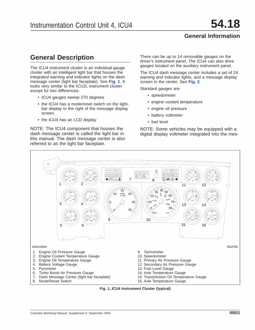
General DescriptionThe ICU4 instrument cluster is an individual-gaugecluster with an intelligent light bar that houses theintegrated warning and indicator lights on the dashmessage center (light bar faceplate). See Fig. 1 . Itlooks very similar to the ICU2L instrument clusterexcept for two differences:
• ICU4 gauges sweep 270 degrees
• the ICU4 has a mode/reset switch on the light-bar display to the right of the message displayscreen
• the ICU4 has an LCD display
NOTE: The ICU4 component that houses thedash message center is called the light bar inthis manual. The dash message center is alsoreferred to as the light bar faceplate.
There can be up to 14 removable gauges on thedriver’s instrument panel. The ICU4 can also drivegauges located on the auxiliary instrument panel.
The ICU4 dash message center includes a set of 24warning and indicator lights, and a message displayscreen in the center. See Fig. 2 .
Standard gauges are:
• speedometer
• engine coolant temperature
• engine oil pressure
• battery voltmeter
• fuel level
NOTE: Some vehicles may be equipped with adigital display voltmeter integrated into the mes-
0 160
10060
PSI
AIR
S
0 160
10060
PSI
AIR
P
110 350
270190
F
TRANS
100 250
200150
F
WATER
E F
1/2
FUEL100 300
200
AXLE
F
100 300
200
AXLE
F
8 16
12
VOLTS
0 80
40
TURBO
PSI
30 150
90
PYRO
100 300
200
OIL
0 100
40
OIL
PSI
10F
F
75
6555
5
15
2535 45
8510
30
5070 90
110
130
km/hMPH
RPMX 100
1520
25
10
5
0 30
04/01/2004 f610706
1 2
3 4
5 6
7 8
9 10
11 12
13 14
15 16
1. Engine Oil Pressure Gauge2. Engine Coolant Temperature Gauge3. Engine Oil Temperature Gauge4. Battery Voltage Gauge5. Pyrometer6. Turbo Boost Air Pressure Gauge7. Dash Message Center (light bar faceplate)8. Mode/Reset Switch
9. Tachometer10. Speedometer11. Primary Air Pressure Gauge12. Secondary Air Pressure Gauge13. Fuel Level Gauge14. Axle Temperature Gauge15. Transmission Oil Temperature Gauge16. Axle Temperature Gauge
Fig. 1, ICU4 Instrument Cluster (typical)
Instrumentation Control Unit 4, ICU4 54.18General Information
Columbia Workshop Manual, Supplement 6, September 2004 050/1

sage display screen instead of a battery voltagegauge. See Fig. 3 .
Gauges with an integrated warning light on thegauge are listed below with an indication of how thewarning light is activated:
• engine coolant temperature (high)
• engine oil pressure (low)
• fuel level (low)
• transmission oil temperature (high)
Other available gauges include:
• tachometer
• engine oil temperature
• transmission oil temperature
• axle temperature; forward-rear, and rear-rear
• ammeter
• air pressure; primary, secondary, application,and suspension
• pyrometer
• turbo boost
Warning and Indicator LightsUp to 24 warning and indicator lights can be installedin the ICU4; the bottom two rows (16 total) are fixed,and the eight positions in the top row are optional.There may also be up to four gauges with a warninglight integrated on the gauge.
The red engine protection (ENGINE PROTECT) lightcomes on to indicate that the protection system avail-able for the engine has been activated. If the enginecoolant temperature, the coolant level, the engine oilpressure, or on some engines, the engine oil tem-perature or the intake air temperature reach presetlevels, the engine will begin a warning and shutdown
f61070706/22/2004
1
2
3
4 5 6 7 8 9 10 11 12 13 14
15
16
171819202122
1. Left Turn Signal2. Check Engine Indicator3. Optional Indicator4. Engine Protection Warning5. Intake Heater Indicator6. Air Filter Indicator7. Water in Fuel Indicator8. Message Display Screen9. Mode/Reset Switch10. Tractor ABS Indicator11. Message Indicator
12. Trailer ABS Indicator13. Wheel Spin Indicator14. Check Transmission Indicator15. Optimized Idle Indicator16. Right Turn Signal17. Low Air System Pressure Warning18. High Beam Indicator19. Parking/Emergency Brake Warning20. Fasten Seat Belt Warning21. No Charge Indicator (alternator)22. Low Vehicle Battery Voltage
Fig. 2, ICU4 Dash Message Center (typical)
04/27/2004 f040694
Fig. 3, Message Display Screen with Integrated DigitalVoltmeter
Instrumentation Control Unit 4, ICU454.18General Information
Columbia Workshop Manual, Supplement 6, September 2004050/2

process. The engine ECU will begin to reduce themaximum engine torque and speed and, if the condi-tion does not improve, will shut down the enginewithin 30 seconds of the light illuminating. The drivermust safely bring the vehicle to a stop on the side ofthe road and shut down the engine as soon as thered light is seen. If the engine shuts down while thevehicle is in a hazardous location, the engine can berestarted after turning the key to the OFF position fora few seconds.
The standard warning and indicator lights operate asfollows:
• The green right-turn and left-turn signal lightsflash on and off whenever the outside turn sig-nal lights are flashing.
• The blue high-beam indicator light comes onwhen the headlights are on high beam.
• The yellow CHECK ENGINE indicator comeson when an engine fault is detected or re-corded. The check engine light is controlled bythe engine ECM. See the engine manufactur-er’s manuals for troubleshooting.
• The red low air pressure warning light (a circlewith arrows symbol) and buzzer activate when-ever air pressure in the primary or secondaryair reservoir falls below 64 to 76 psi (440 to525 kPa).
• The red high coolant temperature warning light(located on the engine coolant temperaturegauge) and buzzer activate whenever the cool-ant temperature goes above a maximum levelwhenever the cluster receives a high coolantfault message from the engine (MID 128, PID110, and FMI 00).
• The red low engine oil pressure warning light(located on the engine oil pressure gauge) andbuzzer activate whenever the engine oil pres-sure goes below a minimum level wheneverthe cluster receives a low oil pressure faultmessage from the engine (MID 128, PID 100,and FMI 01).
• The yellow high transmission oil temperatureindicator (located on the optional transmissionoil temperature gauge) activates when thetransmission fluid temperature goes above amaximum level specified by the transmissionmanufacturer. This telltale is directly controlledby the transmission via hard wire input to thecluster.
• The red parking/emergency brake (BRAKE!)warning light activates whenever the parkingbrake is engaged. A buzzer also activateswhen the vehicle is moving at least 2 mph (3km/h) with the parking brake set.
• The yellow low fuel indicator (located on thefuel gauge) activates when the fuel tank is lessthan 1/8 full.
• The red fasten seat belt warning symbol illumi-nates for 15 seconds when the ignition key isturned to the ON position.
• The yellow INTAKE HEATER indicator illumi-nates to indicate that the intake air heater isactive. This telltale is directly controlled by theengine via hard wire input to the cluster.
• The yellow WATER IN FUEL indicator illumi-nates to indicate that the fuel could containwater. This telltale is directly controlled by theengine via hard wire input to the cluster.
• The yellow tractor ABS (TRACT ABS) indicatorilluminates when a problem with the ABS sys-tem is detected. This telltale is directly con-trolled by the ABS via hard wire input to thecluster.
• The yellow check transmission (CHECKTRANS) indicator illuminates when a problemwith the electronic transmission is detected.This telltale is directly controlled by the trans-mission via hard wire input to the cluster.
• The yellow Optimized Idle (OPT IDLE) indica-tor illuminates on vehicles equipped with a De-troit Diesel engine and the Optimized Idle sys-tem when Optimized Idle is active andcontrolling the engine start and stop functions.This system operates only when the vehicle isstopped and the parking brake is on. This tell-tale is directly controlled by the engine via hardwire input to the cluster.
• The red low vehicle battery voltage warninglight (battery symbol) illuminates when the bat-tery voltage is 11.9 volts or less. This telltale iscontrolled by the cluster by monitoring the volt-age message from the engine.
• The yellow alternator NO CHARGE indicatorilluminates to indicate an alternator charge out-put failure. This telltale is directly controlled bythe alternator via hard wire input to the cluster.
Instrumentation Control Unit 4, ICU4 54.18General Information
Columbia Workshop Manual, Supplement 6, September 2004 050/3
The yellow trailer ABS (TRLR ABS) indicator oper-ates as follows when a compatible trailer is properlyconnected to a tractor before the engine is started(PLC trailers only):
• With the ignition key in the ON position, thetrailer ABS lamp illuminates momentarily, thenturns off.
• If the lamp comes on momentarily during ve-hicle operation, then shuts off, a fault was de-tected and corrected.
• If the lamp comes on and stays on during ve-hicle operation, there is a fault with the trailerABS. Repair the trailer ABS system immedi-ately to ensure full antilock braking capability.
The trailer ABS lamp will not illuminate unless a com-patible trailer is connected to the tractor.
NOTE: When connected to a PLC-equippedtrailer, this telltale is directly controlled by thetractor ABS ECU via hard wire input to thecluster.
On non-PLC-equipped trailers, this telltale isdirectly controlled by the trailer ABS ECU viahard wire input to the cluster.
The eight warning and indicator light positions on thetop row of the light bar are optional. Available op-tional indicator lights include: low washer fluid, auto-matic transmission overheat warning, wheel spinwarning, impaired air filter warning, ECAS (electronicsuspension) transfer indicator, and ECAS failurewarning.
Buzzer and ChimeThe buzzer sounds for 3 seconds during the self-testat start-up, and when the following conditions exist:
• low air pressure
• low oil pressure
• high coolant temperature
• the parking brake is applied and the vehicle ismoving at a speed of at least 2 mph (3 km/h)
A friendly chime sounds when the parking brake isoff and the door is open, or when the headlights areon and the door is open.
Ignition SequenceWhen the ignition key is turned on, the ICU4 beginsa self-test. During this process all gauges controlledby the cluster sweep to full scale and return, thebuzzer sounds for 3 seconds, the fasten seat beltwarning light illuminates for 15 seconds, and the fol-lowing warning lights illuminate then turn off: batteryvoltage, low air pressure, parking brake, low oil pres-sure, high coolant temperature, high transmissiontemperature, and low fuel level. Then the softwarerevision level of the ICU4 is displayed, followed byactive faults, if any, then the odometer display.
Instrumentation Control Unit 4, ICU454.18General Information
Columbia Workshop Manual, Supplement 6, September 2004050/4

ReplacementTo replace the following components, refer to the in-dicated subject.
• Individual gauges, see Subject 110
• Light bar, see Subject 120
• Light bulbs or telltales, see Subject 130
ICU41. Remove the left-hand dash panels. Be sure the
screws attaching the dash panel trimtop to theupper dash assembly have been removed. Forinstructions, see Section 60.08 , Subject 100.
2. Remove the screw that attaches the dash paneltrimtop to the lower dash panel. This screw islocated on the far left of the trimtop.
3. Remove the fasteners that secure the driver’sinstrument panel. Fasteners used on the ICU4are 7/8" Torx pan-head dog-point screws. SeeFig. 1 .
CAUTIONElectronic components of the ICU are vulnerableto damage from static electricity. If available,wear a wrist grounding strap connected to aground in the cab or workbench. If a groundingstrap is not available, touch a grounded compo-nent immediately before doing any work whichcould bring a tool or body part in contact withICU circuitry.
4. Disconnect the electrical harness connectorsfrom the back of the light bar. These include the32-pin light bar connector, the 24-pin light barconnector, and the two 6-pin gauge databus con-nectors. Also disconnect the 3-pin auxiliary inputconnector, if so equipped. See Fig. 2 .
IMPORTANT: Bleed off all air before trying toremove the air hoses.
5. Using a paint pen, mark the air hoses for ease ofinstallation. After bleeding all air from the system,disconnect all air gauge hoses.
6. Remove the light bar faceplate by placing asmall flat blade under each end near the centerand carefully pry it forward to release the lockingtabs.
7. When all fasteners and connections between thecluster and the dash have been disconnected,remove the old ICU from the dash. See Fig. 3 .
8. Remove the light bar from the back by removingits four Torx mounting capscrews from the frontof the ICU4. The top two mounting capscrewsalso secure the trimtop to the cluster housing.
9. Disconnect each gauge from the others by dis-connecting the daisy chain harness connectors.
NOTE: Record the location of each gauge be-fore removing them if the same configuration isdesired for reinstallation. Gauges must be in-stalled in the appropriate size panel opening,and they must all be connected to each other indaisy-chain fashion in order to work, but a spe-cific location for each gauge is not necessary.
10. Remove all gauges. See Fig. 4 .
10.1 To remove the speedometer and tachom-eter, remove the two Torx mounting cap-
1
2
2
3
2
f54470006/28/2004
1. #10 Stainless Steel Flat Washer, 1/2" O.D.2. 7/8" Dog-Point Torx Mounting Capscrew3. ICU4 Cluster
Fig. 1, ICU4 Dash Panel Installation
Instrumentation Control Unit 4, ICU4 54.18ICU4 Replacement
Columbia Workshop Manual, Supplement 6, September 2004 100/1

screws that secure the mounting bracketand the gauge to the cluster.
10.2 For small gauges, push in and twist theblack plastic gauge mounting collar coun-terclockwise slightly until the collar unlocksfrom the gauge. Remove the gaugethrough the front of the opening and thecollar and wave ring from the back.
11. Remove the remaining screw that attaches thedash panel trimtop to the old ICU.
12. Attach the dash panel trimtop to the replacementICU cluster housing.
13. Install the gauges in their appropriate openings.See Fig. 4 .
13.1 For the speedometer and tachometer, ori-ent the gauge and place it through theopening from the front. Then place themounting bracket on the back of thegauge and install the two Torx mountingcapscrews.
13.2 For small gauges, orient the gauge andplace it through the front of the opening,and place the collar and wave ring fromthe back. Push the gauge mounting collaragainst the wave ring and twist the collarclockwise until the collar locks in place.
14. Install the light bar. Place it into the opening fromthe back and install its four Torx mounting cap-
screws from the front of the ICU4. The top twomounting capscrews also secure the trimtop tothe cluster housing. Hold the triptop so its mount-ing tabs are flush to the cluster, then secure thelight bar. See Fig. 3 .
15. Install the light bar faceplate by placing it overthe front of the light bar, then carefully press it onuntil its end tabs lock in place.
16. Connect each gauge to the others on each sideof the cluster by connecting the harnesses in adaisy-chain fashion.
16.1 Start by connecting the inside harness ofone of the two large gauges to the closest6-pin connector on the light bar. Then con-nect the harness on the outside of thegauge to the nearest plug at the top of thecolumn of small gauges next to it. Con-nect the other harness from the smallgauge to the one below it. Continue work-ing down, then across the bottom to thecolumn of gauges next to it, then up thecolumn. The final gauge in the chain willconnect only to the gauge immediatelybelow it.
16.2 Connect the gauges on the other side ofthe cluster in similar fashion. Start with theother large gauge, connect it to the near-est 6-pin connector on the light bar, thenconnect the other harness from the largegauge to the small gauge nearest on the
8 7 6 5 4 3 2 1
1 2 2
4 5
f54444307/16/2004
3 3
C16 C1 A12 A1
B1B12D1D1612
34
56
12
34
56
123
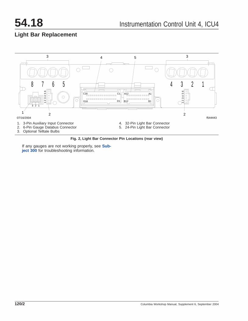
1. 3-Pin Auxiliary Input Connector2. 6-Pin Gauge Databus Connector3. Optional Telltale Bulbs
4. 32-Pin Light Bar Connector5. 24-Pin Light Bar Connector
Fig. 2, Light Bar Connector Pin Locations (rear view)
Instrumentation Control Unit 4, ICU454.18ICU4 Replacement
Columbia Workshop Manual, Supplement 6, September 2004100/2
top inside column and work similarly downthe inside column and up the outside col-umn around so all gauges are connectedin the chain.
17. Place the ICU4 cluster close to its dash openingand connect the air hoses to the air gauges asmarked on removal.
18. Connect all remaining electrical harnesses to theback of the light bar. These include the 32-pinlight bar harness connector, the 24-pin light barharness connector, and the 3-pin auxiliary inputharness connector, if so equipped. See Fig. 2 .
19. Install the fasteners that secure the cluster to thedash. Fasteners used on the ICU4 are 7/8" Torxpan-head dog-point screws. See Fig. 1 .
20. Install all remaining dash panels. Be sure to in-stall the fasteners that attach the dash paneltrimtop to the upper dash assembly and lowerdash panel. For instructions, see Section 60.08 ,Subject 100.
21. Turn on the ignition and test the operation of theICU. All gauges controlled by the cluster sweepto full scale and return, the buzzer sounds for 3seconds, the fasten seat belt warning light illumi-nates for 15 seconds, and the battery voltage,low air pressure and parking brake warning lightsilluminate then turn off.
If any gauges are not working properly, see Sub-ject 300 for troubleshooting information.
f610704
1
2
3
4
4
5
6
03/29/2004
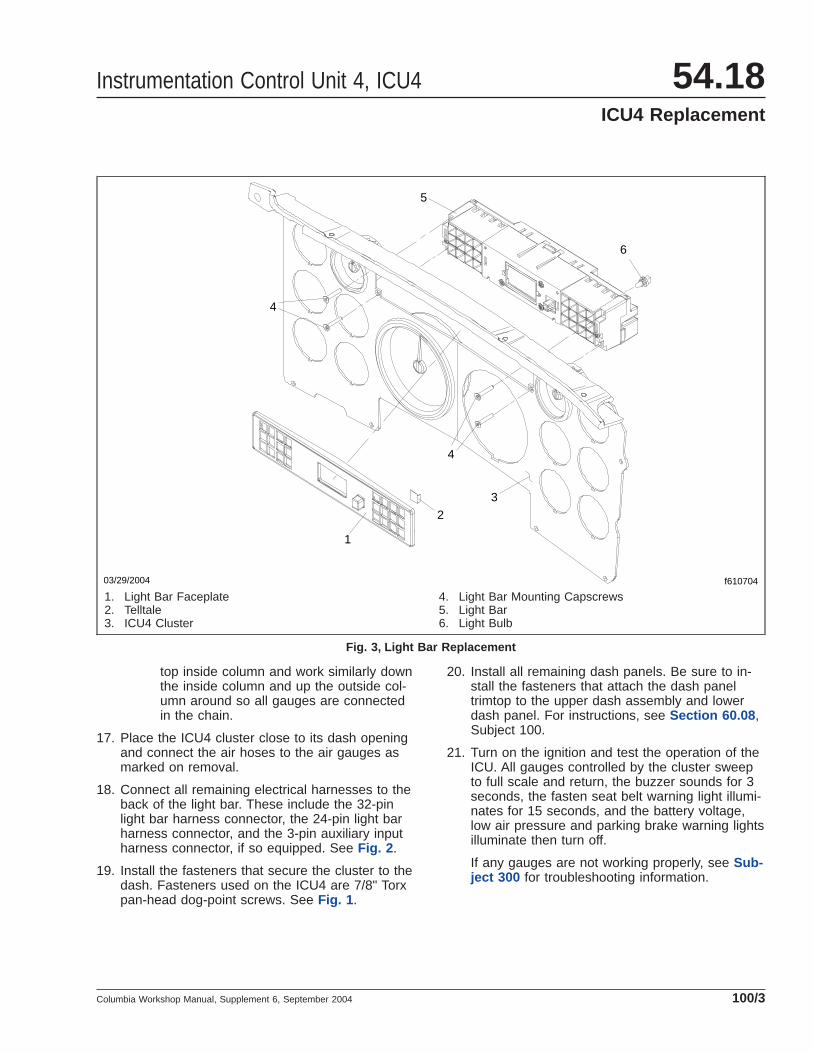
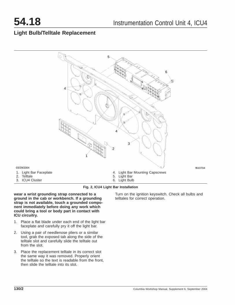
1. Light Bar Faceplate2. Telltale3. ICU4 Cluster
4. Light Bar Mounting Capscrews5. Light Bar6. Light Bulb
Fig. 3, Light Bar Replacement
Instrumentation Control Unit 4, ICU4 54.18ICU4 Replacement
Columbia Workshop Manual, Supplement 6, September 2004 100/3

03/30/2004 f610705
12
34
5
6
78
7
8
1. ICU4 Cluster Housing2. Air Pressure Gauge3. Small Gauge4. Large Gauge (Speedometer or Tachometer)
5. Large Gauge Mounting Bracket6. Large Gauge Mounting Capscrews7. Wave Ring8. Small Gauge Mounting Collar
Fig. 4, ICU4 Gauge Installation
Instrumentation Control Unit 4, ICU454.18ICU4 Replacement
Columbia Workshop Manual, Supplement 6, September 2004100/4

Use the instructions for removing the dash panelsthat follow to access the back to the ICU4. Then goto the appropriate instructions to replace each type ofgauge. Then use the instructions at the end of thesubject for installing the dash panels.
Removing the Dash Panels1. Remove the left-hand dash panels. Be sure the
screws attaching the dash panel trimtop to theupper dash assembly have been removed. Forinstructions, see Section 60.08 , Subject 100.
2. Remove the screw that attaches the dash paneltrimtop to the lower dash panel. This screw islocated on the far left of the trimtop.
3. Remove the fasteners that secure the driver’sinstrument panel. Fasteners used on the ICU4are 7/8" Torx pan-head dog-point screws. SeeFig. 1 .
CAUTIONElectronic components of the ICU are vulnerableto damage from static electricity. If available,
wear a wrist grounding strap connected to aground in the cab or workbench. If a groundingstrap is not available, touch a grounded compo-nent immediately before doing any work whichcould bring a tool or body part in contact withICU circuitry.
4. Carefully pull the dash panel forward to gain ac-cess to the gauges from behind the panel.
Speedometer and Tachometer1. Disconnect the electrical harness connectors
from the back of the gauge.
2. Remove the two Torx mounting capscrews thatsecure the mounting bracket and the gauge tothe cluster. See Fig. 2 .
3. Orient the replacement gauge and place itthrough the opening from the front. Then placethe mounting bracket on the back of the gaugeand install the two Torx mounting capscrews.
4. Connect both wire harnesses to the back of thegauge.
5. See the instructions that follow to install the dashpanels.
Air Pressure GaugesIMPORTANT: Bleed off all air before trying toremove the air hoses.
1. Using a paint pen, mark the air hoses for ease ofinstallation. After bleeding all air from the system,disconnect the air gauge hoses.
2. Unplug both wire harnesses from the back of thegauge.
3. Note the location of each gauge before removingthem if multiple gauges are being replaced. Toremove the gauge, push in and twist the blackplastic gauge mounting collar counterclockwiseslightly until the collar unlocks from the gauge.Remove the gauge through the front of the open-ing and the collar and wave ring from the back.See Fig. 2 .
4. Orient the replacement gauge and place itthrough the front of the opening, and place thecollar and wave ring from the back. Push the
1
2
2
3
2
f54470006/28/2004
1. #10 Stainless Steel Flat Washer, 1/2" O.D.2. 7/8" Dog-Point Torx Mounting Capscrew3. ICU4 Cluster
Fig. 1, ICU4 Dash Panel Installation
Instrumentation Control Unit 4, ICU4 54.18Gauge Replacement
Columbia Workshop Manual, Supplement 6, September 2004 110/1

gauge mounting collar against the wave ring andtwist the collar clockwise until the collar locks inplace.
5. Connect both wire harnesses to the back of thegauge.
6. Connect the air gauge hoses.
7. See the instructions that follow to install the dashpanels.
All Other Gauges1. Unplug both wire harnesses from the back of the
gauge.
2. Note the location of each gauge before removingthem if multiple gauges are being replaced. Toremove the gauge, push in and twist the blackplastic gauge mounting collar counterclockwiseslightly until the collar unlocks from the gauge.Remove the gauge through the front of the open-ing, and the collar and wave ring from the back.See Fig. 2 .
3. Orient the replacement gauge and place itthrough the front of the opening, and place thecollar and wave ring from the back. Push thegauge mounting collar against the wave ring andtwist the collar clockwise until the collar locks inplace.
4. Connect both wire harnesses to the back of thegauge.
03/30/2004 f610705
12
34
5
6
78
7
8
1. ICU4 Cluster Housing2. Air Pressure Gauge3. Small Gauge4. Large Gauge (Speedometer or Tachometer)
5. Large Gauge Mounting Bracket6. Large Gauge Mounting Capscrews7. Wave Ring8. Small Gauge Mounting Collar
Fig. 2, ICU4 Gauge Installation
Instrumentation Control Unit 4, ICU454.18Gauge Replacement
Columbia Workshop Manual, Supplement 6, September 2004110/2

5. See the instructions that follow to install the dashpanels.
Installing the Dash Panels1. Install the fasteners that secure the cluster to the
dash. Fasteners used on the ICU4 are 7/8" Torxpan-head dog-point screws. See Fig. 1 .
2. Install all remaining dash panels. Be sure to in-stall the fasteners that attach the dash paneltrimtop to the upper dash assembly and lowerdash panel. For instructions, see Section 60.08 ,Subject 100.
3. Turn on the ignition and test the operation of theICU. All gauges controlled by the cluster sweepto full scale and return, the buzzer sounds for 3seconds, the fasten seat belt warning light illumi-nates for 15 seconds, and the battery voltage,low air pressure and parking brake warning lightsilluminate then turn off.
If any gauges are not working properly, see Sub-ject 300 for troubleshooting information.
Instrumentation Control Unit 4, ICU4 54.18Gauge Replacement
Columbia Workshop Manual, Supplement 6, September 2004 110/3


Light Bar Replacement1. Remove the left-hand dash panels. Be sure the
screws attaching the dash panel trimtop to theupper dash assembly have been removed. Forinstructions, see Section 60.08 , Subject 100.
2. Remove the screw that attaches the dash paneltrimtop to the lower dash panel. This screw islocated on the far left of the trimtop.
3. Remove the fasteners that secure the driver’sinstrument panel. Fasteners used on the ICU4are 7/8" Torx pan-head dog-point screws. SeeFig. 1 .
CAUTIONElectronic components of the ICU are vulnerableto damage from static electricity. If available,wear a wrist grounding strap connected to aground in the cab or workbench. If a groundingstrap is not available, touch a grounded compo-nent immediately before doing any work whichcould bring a tool or body part in contact withICU circuitry.
4. Disconnect the electrical harness connectorsfrom the back of the light bar. These include the32-pin light bar connector, the 24-pin light barconnector, and the two 6-pin gauge databus con-nectors. Also disconnect the 3-pin auxiliary inputconnector, if so equipped. See Fig. 2 .
5. Remove the light bar faceplate by placing asmall flat blade under each end near the centerand carefully pry it forward to release the lockingtabs.
6. Remove the light bar from the back by removingits four Torx mounting capscrews from the frontof the ICU4. The top two mounting capscrewsalso secure the trimtop to the cluster housing.See Fig. 3 .
7. Install the replacement light bar. Place it into theopening from the back and install its four Torxmounting capscrews from the front of the ICU4.The top two mounting capscrews also secure thetrimtop to the cluster housing. Hold the trimtopso its mounting tabs are flush to the cluster, thensecure the light bar. See Fig. 3 .
8. Install the light bar faceplate by placing it overthe front of the light bar, then carefully press it onuntil its end tabs lock in place.
9. Connect the electrical harnesses to the back ofthe light bar; the 32-pin harness connector, the24-pin harness connector, the two 6-pin databusharness connectors from the speedometer andtachometer, and the 3-pin auxiliary input harnessconnector, if so equipped. See Fig. 2 .
10. Install the fasteners that secure the cluster to thedash. Fasteners used on the ICU4 are 7/8" Torxpan-head dog-point screws. See Fig. 1 .
11. Install all remaining dash panels. Be sure to in-stall the fasteners that attach the dash paneltrimtop to the upper dash assembly and lowerdash panel. For instructions, see Section 60.08 ,Subject 100.
12. Turn on the ignition and test the operation of theICU. All gauges controlled by the cluster sweepto full scale and return, the buzzer sounds for 3seconds, the fasten seat belt warning light illumi-nates for 15 seconds, and the battery voltage,low air pressure and parking brake warning lightsilluminate then turn off.
1
2
2
3
2
f54470006/28/2004
1. #10 Stainless Steel Flat Washer, 1/2" O.D.2. 7/8" Dog-Point Torx Mounting Capscrew3. ICU4 Cluster
Fig. 1, ICU4 Dash Panel Installation
Instrumentation Control Unit 4, ICU4 54.18Light Bar Replacement
Columbia Workshop Manual, Supplement 6, September 2004 120/1
If any gauges are not working properly, see Sub-ject 300 for troubleshooting information.
8 7 6 5 4 3 2 1
1 2 2
4 5
f54444307/16/2004
3 3
C16 C1 A12 A1
B1B12D1D1612
34
56
12
34
56
123
1. 3-Pin Auxiliary Input Connector2. 6-Pin Gauge Databus Connector3. Optional Telltale Bulbs
4. 32-Pin Light Bar Connector5. 24-Pin Light Bar Connector
Fig. 2, Light Bar Connector Pin Locations (rear view)
Instrumentation Control Unit 4, ICU454.18Light Bar Replacement
Columbia Workshop Manual, Supplement 6, September 2004120/2

f610704
1
2
3
4
4
5
6
03/29/2004
1. Light Bar Faceplate2. Telltale3. ICU4 Cluster
4. Light Bar Mounting Capscrews5. Light Bar6. Light Bulb
Fig. 3, Light Bar Replacement
Instrumentation Control Unit 4, ICU4 54.18Light Bar Replacement
Columbia Workshop Manual, Supplement 6, September 2004 120/3


Light Bulb ReplacementNOTE: Only the top row of warning and indica-tor lights have replaceable bulbs. The replace-able bulbs are incandescent. All lights in thisrow are optional, so not all positions may be inuse. See the troubleshooting procedures inSubject 300 to diagnose warning and indicatorlight problems and solutions.
1. Remove the left-hand dash panels. Be sure thescrews attaching the dash panel trimtop to theupper dash assembly have been removed. Forinstructions, see Section 60.08 , Subject 100.
2. Remove the screw that attaches the dash paneltrimtop to the lower dash panel. This screw islocated on the far left of the trimtop.
3. Remove the fasteners that secure the driver’sinstrument panel. Fasteners used on the ICU4are 7/8" Torx pan-head dog-point screws. SeeFig. 1 .
CAUTIONElectronic components of the ICU are vulnerableto damage from static electricity. If available,wear a wrist grounding strap connected to aground in the cab or workbench. If a groundingstrap is not available, touch a grounded compo-nent immediately before doing any work whichcould bring a tool or body part in contact withICU circuitry.
4. Carefully pull the dash panel forward to gain ac-cess to the light bar from behind the panel.
5. Twist the burned-out bulb about 1/8-turn counter-clockwise and pull it out from the back of thelight bar. See Fig. 2 .
6. Insert a new bulb into the opening on the back ofthe light bar and twist it about 1/8-turn clockwiseuntil it is securely in place.
7. Install the fasteners that secure the cluster to thedash. Fasteners used on the ICU4 are 7/8" Torxpan-head dog-point screws. See Fig. 1 .
8. Install all remaining dash panels. Be sure to in-stall the fasteners that attach the dash paneltrimtop to the upper dash assembly and lowerdash panel. For instructions, see Section 60.08 ,Subject 100.
9. Turn on the ignition and test the operation of theICU. All gauges controlled by the cluster sweepto full scale and return, the buzzer sounds for 3seconds, the fasten seat belt warning light illumi-nates for 15 seconds, and the battery voltage,low air pressure and parking brake warning lightsilluminate then turn off.
If any gauges are not working properly, see Sub-ject 300 for troubleshooting information.
Telltale ReplacementThe term "telltale" refers to the small plastic lens inthe top row of the light bar faceplate (dash messagecenter) with a warning or indicator message printedon it. These are replaceable.
CAUTIONElectronic components of the ICU are vulnerableto damage from static electricity. If available,
1
2
2
3
2
f54470006/28/2004
1. #10 Stainless Steel Flat Washer, 1/2" O.D.2. 7/8" Dog-Point Torx Mounting Capscrew3. ICU4 Cluster
Fig. 1, ICU4 Dash Panel Installation
Instrumentation Control Unit 4, ICU4 54.18Light Bulb/Telltale Replacement
Columbia Workshop Manual, Supplement 6, September 2004 130/1
wear a wrist grounding strap connected to aground in the cab or workbench. If a groundingstrap is not available, touch a grounded compo-nent immediately before doing any work whichcould bring a tool or body part in contact withICU circuitry.
1. Place a flat blade under each end of the light barfaceplate and carefully pry it off the light bar.
2. Using a pair of needlenose pliers or a similartool, grab the exposed tab along the side of thetelltale slot and carefully slide the telltale outfrom the slot.
3. Place the replacement telltale in its correct slotthe same way it was removed. Properly orientthe telltale so the text is readable from the front,then slide the telltale into its slot.
Turn on the ignition keyswitch. Check all bulbs andtelltales for correct operation.
f610704
1
2
3
4
4
5
6
03/29/2004
1. Light Bar Faceplate2. Telltale3. ICU4 Cluster
4. Light Bar Mounting Capscrews5. Light Bar6. Light Bulb
Fig. 2, ICU4 Light Bar Installation
Instrumentation Control Unit 4, ICU454.18Light Bulb/Telltale Replacement
Columbia Workshop Manual, Supplement 6, September 2004130/2

ContentsGeneral Information
General Troubleshooting Procedure
Fault Code Troubleshooting
Gauge Troubleshooting
Warning Lamp Troubleshooting
Backlighting Troubleshooting
Light Bar LCD Display Fault Messages
Gauge Control Strategy
Warning Lamp Control Strategy
Pin and Circuit Descriptions
Sensor Specifications
List of FiguresFigure 1 — Light Bar Control Unit Block Diagram
Figure 2 — Light Bar Connector Pin Locations (rearview)
Figure 3 — Transmission Oil Temperature SensorResistance (°F)
Figure 4 — Transmission Oil Temperature SensorResistance (°C)
Figure 5 — Axle Oil Temperature Sensor Resistance(°F)
Figure 6 — Axle Oil Temperature Sensor Resistance(°C)
Figure 7 — Ammeter Current Sensor Wiring Dia-gram (InPower)
Figure 8 — Ammeter Current Sensor Output Voltage(–300 to +300 Amp Range)
Figure 9 — Ammeter Current Sensor Output Voltage(–100 to +100 Amp Range)
List of TablesTable 1 — J1587 Fault Code Troubleshooting
Table 2 — Diagnosis for a Single Gauge Not Work-ing
Table 3 — Diagnosis for Multiple Gauges Not Work-ing (databus-driven gauges)
Table 4 — Diagnosis for Inaccurate Gauges
Table 5 — Air Pressure Gauge Diagnosis
Table 6 — Diagnosis for Warning Lamps in the LightBar
Table 7 — Diagnosis for In-Gauge Warning Lamps
Table 8 — Backlighting Troubleshooting (gauges andlight bar)
Table 9 — Roll Call Faults (displayed on the LCDdisplay)
Table 10 — Display Messages After Power-OnSweep
Table 11 — Standard and Optional Gauges—InputTypes
Table 12 — Light Bar Warning Lamp Control
Table 13 — Gauge Warning Lamp Control (warninglamps in gauge)
Table 14 — 24-Pin Light Bar Connector Pin Descrip-tions
Table 15 — 32-Pin Light Bar Connector Pin Descrip-tions
Table 16 — 6-Pin Gauge Databus Connector PinDescriptions
Table 17 — 3-Pin Light Bar Auxiliary Input ConnectorPin Descriptions
Table 18 — Fuel Level Sensor Resistance (Stewart-Warner)
Table 19 — Transmission Oil Temperature Sensor(Hi-Stat) Resistance, Standard Gauge (°F)
Table 20 — Transmission Oil Temperature Sensor(Hi-Stat) Resistance, Metric Gauge (°C)
Table 21 — Axle Oil Temperature Sensor (Hi-Stat)Resistance, Standard Gauge (°F)
Table 22 — Axle Oil Temperature Sensor (Hi-Stat)Resistance, Metric Gauge (°C)
Table 23 — Pyrometer Sensor (with voltage ampli-fier)
Table 24 — InPower Hall-Effect Current Sensor(DCS25; ammeter sensor)
Instrumentation Control Unit 4, ICU4 54.18Troubleshooting
Columbia Workshop Manual, Supplement 13, December 2005 300/1

General InformationThe Ametek ICU4 replaced the Pollak ICU2L in pro-duction on June 7, 2004. The ICU4 consists of indi-vidual gauges, a light bar control unit, and a daisy-chain databus. See Fig. 1 . The light bar is the brainof the system. It contains the warning lamps as wellas an LCD display. The light bar controls all of theindividual gauges except the air pressure gauges.The light bar has two input types to drive the gauges:J1587 data from the engine ECM to control thedatabus-driven gauges, and direct-wired sensor inputto control the other gauges. Each gauge has aunique address that the light bar communicates with.
J1587-driven gauges are the:
• speedometer
• tachometer
• oil pressure gauge
• coolant temperature gauge
• oil temperature gauge
• turbo boost pressure gauge
• voltmeter
Other gauges are the:
• fuel level gauge
• primary air pressure gauge
• secondary air pressure gauge
• application air pressure gauge
• transmission temperature gauge
• forward-rear axle temperature gauge
• rear-rear axle temperature gauge
• pyrometer
• ammeter
• transmission gear display
• cruise control set speed display
General TroubleshootingProcedureFor gauge problems do the following:
1. Check for ICU fault codes (MID 140) and ad-dress these first. See Table 1 for MID 140 fault
code definitions and troubleshooting information.If this solves the problem, no further action isnecessary. If the problem is still present, go tothe next step.
2. Determine whether a single gauge or multiplegauges are malfunctioning. For a single gaugemalfunction, see Table 2 . For multiple gaugesmalfunctioning, see Table 3 .
For gauge accuracy problems, see Table 4 .
For air pressure gauge problems, see Table 5 .
For light bar warning lamp problems, see Table 6 .
For in-gauge warning lamp problems, see Table 7 .
For backlighting problems, see Table 8 .
For a list of possible light bar LCD displayed roll calland power on messages, see Table 9 and Table 10 .
Fault Code TroubleshootingThis section defines fault codes that originate fromthe instrument cluster light bar (MID 140). UseTable 1 to diagnose all MID 140 fault codes.
12
3
4
5
f544439
6
6
07/16/2004
1. A-Panel Gauges2. Light Bar Control
Unit (LBCU)3. B-Panel Gauges4. J1587 Databus
5. Engine6. Cluster Databus
(jumper wires ordaisy chain)
Fig. 1, Light Bar Control Unit Block Diagram
Instrumentation Control Unit 4, ICU454.18Troubleshooting
Columbia Workshop Manual, Supplement 13, December 2005300/2

J1587 Fault Code Troubleshooting
MID PID/SID FMI Fault Code Description Action
140 p168 1 Light bar voltage too low (less than 10.5 volts) Check voltage supply to light bar.Repair as necessary.
140 s240 12 Light bar program memory failure Replace the light bar.
140 s254 12 Light bar controller failure Replace the light bar.
Table 1, J1587 Fault Code Troubleshooting
Gauge TroubleshootingThe tables in this section detail specific troubleshoot-ing procedures for gauge problems. Use Table 2 for
diagnosing a single gauge that does not work. Formultiple gauge failures, use Table 3 . For gauge inac-curacy problems, use Table 4 . Use Table 5 totroubleshoot air pressure gauges.
Diagnosis for a Single Gauge Not Working
TestNo. Test Description Test
Result Action
1 Does the gauge sweep when the ignition is turnedon?
Yes Go to Test 4.
No Go to Test 2.
2Is this particular gauge the last one in the chain fromthe light bar? (If so, it will be one of the gauges thathas only one jumper wire connected to it.)
Yes Go to Test 3.
No Replace the gauge.
3 Remove the jumper wire to this gauge and install aknown good wire. Does the gauge now work?
Yes Replace the jumper wire.
No Replace the gauge.
4 Is the gauge driven by direct sensor input to the lightbar? (See Table 11 for gauge control strategy.)
Yes
If the gauge is just inaccurate, the sensor may bedefective. See Table 4 for diagnosis.
If the gauge is not working, check the sender andsender wiring to the light bar. See Table 18 ,Table 19 , Table 20 , Table 21 , Table 22 , Table 23 ,and Table 24 for sender specifications.
If no problem is found with the sender or senderwiring, the light bar may be defective.
No Go to Test 5.
5Connect ServiceLink to vehicle and open theAmetek ICU4 Instrument Cluster Datalink Monitortemplate. Does the gauge work on the template?
Yes Replace the light bar.
NoCheck the sensor that drives gauge. It will usuallybe an input to the engine ECM. Repair asnecessary.
Table 2, Diagnosis for a Single Gauge Not Working
Diagnosis for Multiple Gauges Not Working (databus-driven gauges)
TestNo. Test Description Test
Result Action
1 Do the affected gauges sweep when the ignition isturned on?
Yes Go to Test 2.
No Go to Test 8.
Instrumentation Control Unit 4, ICU4 54.18Troubleshooting
Columbia Workshop Manual, Supplement 13, December 2005 300/3
Diagnosis for Multiple Gauges Not Working (databus-driven gauges)
TestNo. Test Description Test
Result Action
2
Are the only affected gauges sensor driven by directinput to the light bar (gauges not J1587 databusdriven)?
See Table 11 for gauge control strategy.
Yes
If the affected gauges are one or more of thefollowing: transmission temp, ammeter, and axletemp #3, then check the common sensor groundthat connects to pin C12. If okay, the light bar isprobably faulty.
If the gauges above are not affected, then the lightbar is probably faulty. Repair as necessary.
No Go to Test 3.
3Are only J1587 driven gauges affected?
See Table 11 for gauge control strategy.
Yes Go to Test 4.
No Replace the light bar.
4 Connect PC to vehicle and start Servicelink. WillServicelink connect?
Yes Go to Test 5.
No
Assuming Servicelink and the vehicle adapter areworking correctly, the most likely cause is somethingtaking the entire J1587 databus down (short, etc.).Repair as necessary.
5 In Servicelink, does the ICU4 show up in the ECUlist (MID 140)?
Yes Go to Test 6.
No Check the J1587 databus to the ICU. If okay, thelight bar is probably faulty. Repair as necessary.
6 In Servicelink, does the engine ECM show up in theECU list (MID 128)?
Yes Go to Test 7.
NoCheck the J1587 databus to the engine ECM. Ifokay, the engine ECM is probably faulty. Repair asnecessary.
7In Servicelink, open the Ametek ICU4 InstrumentCluster Datalink Monitor template. Do the affectedgauges work on the template?
Yes Replace the light bar.
No The engine ECM sensor wiring or the engine ECMitself is probably faulty. Repair as necessary.
8 Do any of the gauges sweep when the ignition isturned on?
Yes Go to Test 9.
No Check power and ground to the light bar. If okay, thelight bar is probably faulty. Repair as necessary.
9 Are all of the affected gauges in sequence with oneanother on the daisy chain?
Yes Go to Test 10.
No Replace the light bar.
10
Locate the faulty gauge that is closest to the lightbar in the daisy chain. Replace the jumper wirebetween this gauge and the next gauge closest tothe light bar that works (or the light bar itself). Dothe gauges now work?
Yes Replace the jumper wire.
No Replace the light bar.
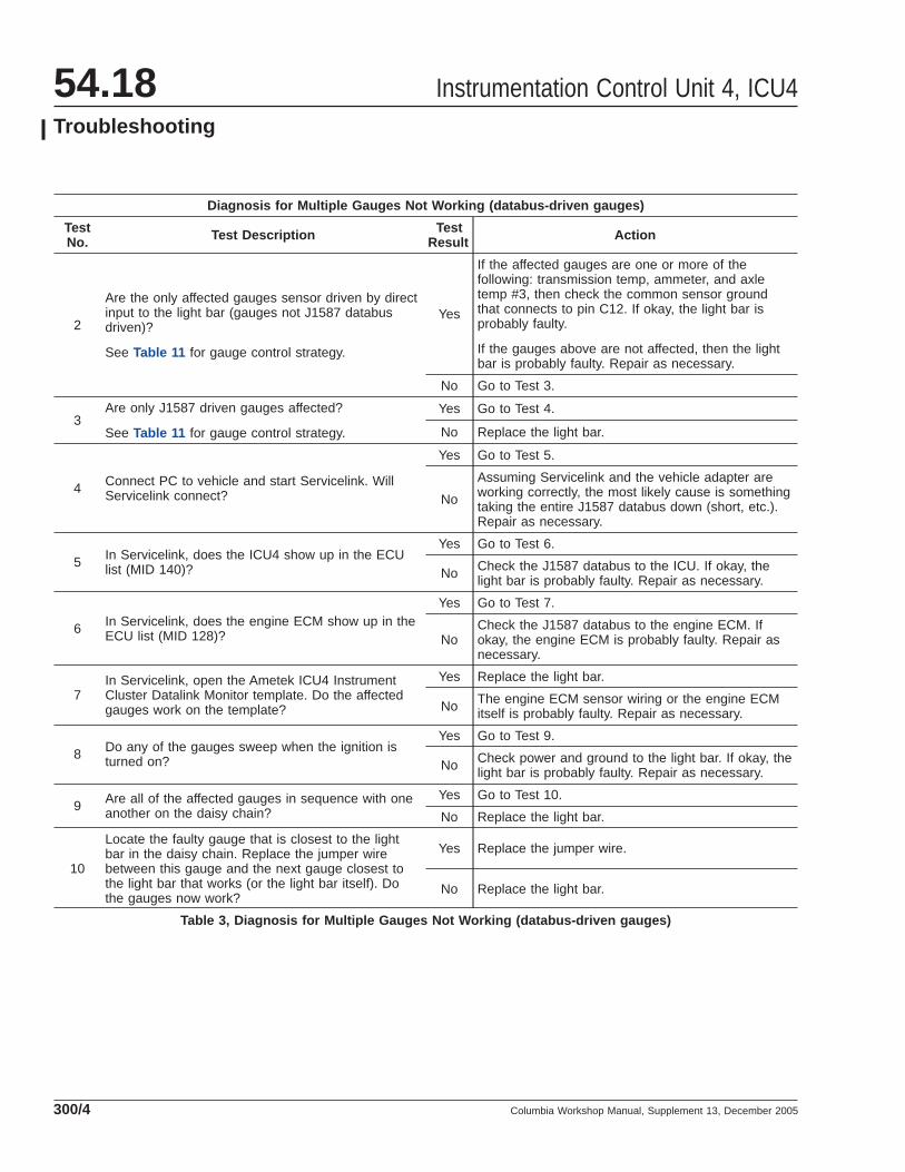
Table 3, Diagnosis for Multiple Gauges Not Working (databus-driven gauges)
Instrumentation Control Unit 4, ICU454.18Troubleshooting
Columbia Workshop Manual, Supplement 13, December 2005300/4

Diagnosis for Inaccurate Gauges
TestNo. Test Description Test
Result Action
1 Is the gauge controlled by the J1587 databus? SeeTable 11 to determine gauge control strategy.
Yes Go to Test 2.
No Go to Test 3.
2
Using the Ametek ICU4 Instrument Cluster DatalinkMonitor template within Servicelink, check if thetemplate gauge reads the same as the clustergauge. Does the template gauge read the same asthe cluster gauge?
Yes
The gauge is okay. The sensor connected to theengine ECM may be faulty. See enginemanufacturer’s literature for troubleshootinginformation.
No Try a known good gauge. If this does not correct theproblem, replace the light bar.
3
For sensor driven gauges, check if gauge sensorresistance or (voltage for ammeter, and earlyproduction pyrometers) matches the specified valuesfor a given temperature (or amperage for ammeter).See Table 18 , Table 19 , Table 20 , Table 21 ,Table 22 , Table 23 , and Table 24 .
NOTE: An accurate thermometer or ammeter willhave to be used to determine appropriate sensorvalues.
Does the sensor resistance (or voltage for theammeter, and early production pyrometers) matchthe published values?
Yes Go to Test 4.
No Replace the sensor.
4
Repeat Test 3, except take the readings at the lightbar connector (disconnect the connector). SeeFig. 2 , and Table 14 and Table 15 . See Table 18 ,Table 19 , Table 20 , Table 21 , Table 22 , Table 23 ,and Table 24 for sensor values.
Does the sensor resistance (or voltage for theammeter, and early production pyrometers) matchthe published values?
Yes Try a known good gauge. If this does not correct theproblem, replace the light bar.
No Repair sensor wiring as necessary.
Table 4, Diagnosis for Inaccurate Gauges
Air Pressure Gauge Diagnosis
TestNo. Test Description Test Result Action
1 Which air pressure gauge is not functioningcorrectly?
Primary orsecondary Go to Test 2.
Application Go to Test 3.
Suspension Go to Test 4.
Instrumentation Control Unit 4, ICU4 54.18Troubleshooting
Columbia Workshop Manual, Supplement 13, December 2005 300/5

Air Pressure Gauge Diagnosis
TestNo. Test Description Test Result Action
2
Drain the air tanks.
Connect an accurate pressure gauge to the primaryor secondary air tank (whichever one correspondswith the problem gauge).
Start the engine and build air pressure until thecompressor cuts out.
Is the air pressure gauge in the cluster within 6 psi(41 kPa) of the test gauge?
Yes No problem found.
No Check for kinked air lines to the gauge. IfOK, replace the gauge.
3
Connect an accurate pressure gauge to a deliveryport on the foot valve.
Make a 90 psi (620 kPa) brake application whileobserving the application air pressure gauge in thecluster and the test gauge.
Is the air pressure gauge in the cluster within 3 psi(21 kPa) of the test gauge?
Yes No problem found.
No Check for kinked air lines to the gauge. IfOK, replace the gauge.
4
Connect an accurate pressure gauge to the airsuspension.
Is the air pressure gauge in the cluster within 3 psi(21 kPa) of the test gauge?
Yes No problem found.
No Check for kinked air lines to the gauge.. IfOK, replace the gauge.
Table 5, Air Pressure Gauge Diagnosis
Warning LampTroubleshootingUse Table 6 to diagnose light bar warning lampproblems, and Table 7 for in-gauge warning lampproblems.
Diagnosis for Warning Lamps in the Light Bar
TestNo. Test Description Test
Result Action
1 What is the problem with the warning lamp?Stays on Go to Test 8.
Does notturn on Go to Test 2.
2
Is the warning lamp one of the following?
• Park Brake/Brake Warning
• Low Air Pressure
• Low Battery Voltage
• Fasten Seatbelt
Yes Go to Test 3.
No Go to Test 4.
Instrumentation Control Unit 4, ICU454.18Troubleshooting
Columbia Workshop Manual, Supplement 13, December 2005300/6

Diagnosis for Warning Lamps in the Light Bar
TestNo. Test Description Test
Result Action
3 Does the warning lamp turn on when the ignition isturned on?
Yes No problem found.
No Replace the light bar.
4 Is the warning lamp activated by a ground input or+12V input? See Table 12 .
12Vactivated Go to Test 5.
Groundactivated Go to Test 6.
5
Disconnect the light bar connector that contains thecircuit for the warning lamp that is not working (seeFig. 2 , and Table 14 and Table 15 ).
Turn the ignition on and activate the circuit thatcontrols the warning lamp (for example, turn on theleft turn signal for the left turn warning lamp). SeeFig. 2 , and Table 14 and Table 15 .
Check for voltage at the light bar connector pin thatcorresponds to that warning lamp. What is thevoltage?
NOTE: For turn signal circuits, the voltage willalternate between 12V and 0V.
12V Replace the light bar.
0V Check circuit that controls warning lamp andrepair as necessary.
6 Is the warning lamp one of the optional warninglamps (top row of light bar)?
Yes Check the bulb and replace if necessary. If thebulb is okay, go to Test 7.
No Go to Test 7.
7
Locate the light bar connector and circuit thatcontrols the warning lamp (see Fig. 2 , andTable 14 and Table 15 ).
Using a jumper to ground, backprobe the pin thatcorresponds to the problem warning lamp.
Does the warning lamp turn on?
Yes Problem is in the circuit that controls the warninglamp, repair as necessary.
No Replace the light bar.
8 Is the warning lamp that stays on the Low AirPressure warning lamp?
Yes Go to Test 11.
No Go to Test 9.
9 Is the problem with the Low Battery Voltagewarning lamp?
Yes
Within Servicelink, open the Ametek ICU4Instrument Cluster Datalink Monitor template andstart the engine. Check the voltmeter voltage onthe template. If the voltage is below 11.9V, checkand repair the vehicle charging system or powerand ground circuits to the engine ECM. If thevoltage is above 11.9V, replace the light bar.
No Go to Test 10.
10 Is the problem with the Fasten Seatbelt warninglamp?
YesIf the Fasten Seatbelt warning lamp does not turnoff approximately 15 seconds after the ignition isturned ON, then replace the light bar.
No Go to Test 12.
Instrumentation Control Unit 4, ICU4 54.18Troubleshooting
Columbia Workshop Manual, Supplement 13, December 2005 300/7

Diagnosis for Warning Lamps in the Light Bar
TestNo. Test Description Test
Result Action
11
Turn the ignition ON.
Using a jumper to ground, backprobe pin A3 of the24-pin light bar connector.
Does the Low Air Pressure warning lamp turn off?
Yes
Either the air brake system pressure is too low orthe problem is in the low air pressure warningcircuit that controls the warning lamp. Repair asnecessary.
No Replace the light bar.
12 Is the warning lamp activated by a ground input or+12V input? See Table 12 .
12Vactivated Go to Test 13.
Groundactivated Go to Test 14.
13
Disconnect the connector that contains the circuitfor the warning lamp that stays on (see Fig. 2 , andTable 14 and Table 15 ).
Turn the ignition ON.
Check for voltage at the light bar connector pin thatcorresponds to the warning lamp.
What is the voltage?
12V
The problem is not with the light bar. Check thesystem that controls the warning lamp for faults(the light may be on for a reason other than afaulty warning lamp circuit). Otherwise, checkwarning lamp circuit for short to power and repairas necessary.
0V Replace the light bar.
14
Disconnect the connector that contains the circuitfor the warning lamp that stays on (see Fig. 2 , andTable 14 and Table 15 ).
Turn the ignition ON.
Check for voltage at the light bar connector pin thatcorresponds to the warning lamp by connecting thepositive meter lead to battery (+) and the negativelead to the connector pin that corresponds to thewarning lamp.
What is the voltage?
12V
The problem is not with the light bar. Check thesystem that controls the warning lamp for faults(the light may be on for a reason other than afaulty warning lamp circuit). Otherwise, checkwarning lamp circuit for short to ground and repairas necessary.
0V Replace the light bar.
Table 6, Diagnosis for Warning Lamps in the Light Bar
Diagnosis for In-Gauge Warning Lamps
TestNo. Test Description Test
Result Action
1 Does the warning lamp illuminate during the ignitionon gauge sweep?
Yes Go to Test 2.
No Replace the gauge.
2
Is the problem with either one of the following gaugewarning lamps?
• Low Oil Pressure
• High Coolant Temperature
Yes Go to Test 3.
No Go to Test 5.
Instrumentation Control Unit 4, ICU454.18Troubleshooting
Columbia Workshop Manual, Supplement 13, December 2005300/8

Diagnosis for In-Gauge Warning Lamps
TestNo. Test Description Test
Result Action
3 Is the problem that the warning lamp stays on?
Yes Go to Test 4.
No
The warning lamp is probably not illuminatingbecause it is not receiving an active fault code fromthe engine ECM:
• 128 p100 01 (oil pressure too low)
• 128 p110 00 (coolant temp too high)
If the appropriate code is active and the warninglamp does not work, then the light bar is probablyfaulty.
4
Check for either of the following engine fault codes:
• 128 p100 01 (oil pressure too low)
• 128 p110 00 (coolant temp too high)
Are either of these faults active?
Yes Check for a problem in the engine’s lubrication orcooling system. Repair as necessary.
No Replace the light bar.
5 Is the problem with the High Transmission Tempera-ture warning lamp?
Yes Go to Test 6.
No Go to Test 9.
6 Is the problem that the warning lamp stays on?Yes Go to Test 8.
No Go to Test 7.
7
Using a jumper to ground, backprobe pin A4 of the24-pin connector.
Does the High Transmission Temperature warninglamp turn on?
Yes The problem is in the circuit that controls the warn-ing lamp. Repair as necessary.
No Replace the light bar.
8
Disconnect the 24-pin light bar connector.
Turn the ignition ON.
Check for voltage at the 24-pin light bar connectorpin A4 by connecting the positive meter lead to bat-tery (+) and the negative lead to pin A4.
12V
The problem is not with the light bar. Check thetransmission for faults (the light may be on for a rea-son other than a faulty warning lamp circuit). Other-wise, check warning lamp circuit for short to groundand repair as necessary.
0V Replace the light bar.
9 Is the problem that the Low Fuel Level warning lampstays on?
Yes Go to Test 10.
No Go to Test 11.
10 Does the fuel gauge read below 1/8?Yes Normal condition; no further action is necessary.
No Replace the light bar.
11 Does the fuel gauge read below 1/8?
Yes Replace the light bar.
NoThe warning lamp should not turn on until the fuellevel is 1/8 or less for at least 60 seconds. No prob-lem found.
Table 7, Diagnosis for In-Gauge Warning Lamps
Instrumentation Control Unit 4, ICU4 54.18Troubleshooting
Columbia Workshop Manual, Supplement 13, December 2005 300/9

Backlighting TroubleshootingFor backlighting problems, see Table 8 .
NOTE: The backlighting signal to the light bar isa pulse-width-modulated (PWM) signal at ap-proximately 320 Hz.
Backlighting Troubleshooting (gauges and light bar)
TestNo. Test Description Test
Result Action
1 Does any of the backlighting work (i.e. panelswitches, etc.)?
Yes Go to Test 2.
No Check the panel lamp dimmer switch, and panellighting circuit. Repair as necessary.
2 Is all the cluster backlighting dead (light bar LCDand all gauges)?
Yes Go to Test 3.
No Go to Test 5.
3
Disconnect the light bar 24-pin connector (seeFig. 2 ).
Turn the headlamps ON, and the panel lamp dimmerswitch to full bright.
Measure the voltage at connector pin A1; it shouldbe approximately +12V.
What is the voltage?
12V Go to Test 4.
0VCheck backlighting circuit 29A for open between theinstrument cluster and splice to other dashcomponents. Repair as necessary.
4
Disconnect both the light bar 24-pin and 32-pinconnectors (see Fig. 2 ).
Turn the headlamps ON, and the panel lamp dimmerswitch to full bright.
Measure the voltage between pin A1 (24-pinconnector) and pin D3 (32-pin connector).
What is the voltage?
12V Replace the light bar.
0V Check panel lamp ground circuit. Repair asnecessary.
5 Is the light bar LCD backlighting the only thing withdead backlighting?
Yes Replace the light bar.
No Go to Test 6.
6 Is only one gauge backlight dead?Yes Go to Test 7.
No Go to Test 8.
7 Is the gauge with dead backlighting the last gauge inthe daisy chain (farthest from the light bar)?
Yes
Try a known good jumper wire to the gauge. Ifbacklight now works on this gauge, this solved theproblem. If the backlighting still does not work,replace the gauge.
No Replace the gauge.
8 Are all the gauges with dead backlighting insequence with one another in the daisy-chain?
Yes
Try a known good jumper wire between the gaugewith dead backlighting that is closest to the light barand the next good gauge (one closer to light bar). Ifall backlighting now works, the jumper solved theproblem. If not, replace all gauges with deadbacklighting.
No Go to Test 9.
Instrumentation Control Unit 4, ICU454.18Troubleshooting
Columbia Workshop Manual, Supplement 13, December 2005300/10

Backlighting Troubleshooting (gauges and light bar)
TestNo. Test Description Test
Result Action
9 Is one of the dead gauges the last gauge in thedaisy-chain (farthest from the light bar)?
Yes
Try a known good jumper to the last gauge. If thelast gauge now works, the jumper solved theproblem to this gauge. Replace all other gauges withdead backlighting.
If the jumper did not correct the backlighting to thelast gauge in the daisy-chain, replace all gaugeswith dead backlighting.
No Replace all gauges with dead backlighting.
Table 8, Backlighting Troubleshooting (gauges and light bar)
Light Bar LCD Display FaultMessagesThis section defines possible fault messages dis-played on the light bar LCD display. Table 9 lists
possible roll call faults and Table 10 lists possiblepower on fault messages. Roll call faults are ECUsthat do not respond during power up.
Roll Call Faults (displayed on the LCD display)
DisplayedMessage Description
NO ENG The ICU is unable to communicate with the engine ECM on the J1587 databus. Check databus wiring,repair as necessary.
NO ABS The ICU is unable to communicate with the ABS on the J1587 databus. Check databus wiring, repair asnecessary.
NO DATA The light bar is not communicating with the J1587 databus.
Table 9, Roll Call Faults (displayed on the LCD display)
Display Messages After Power-On Sweep
Message System With Active Fault Message System With Active Fault
ICU 140 Instrumentation Control Unit (ICU4) TCU 130 Transmission Control Unit
AC 146 Air Conditioning system (front unit) TSU 223 Transmission Shift Unit
ECU 128 Engine Control Unit (engine ECM) AC 200 Air Conditioning system (rear unit)
ABS 136 Anti-lock Brake System SBU 232 Seat Belt Unit (SPACE/Airbag system)
CDU 219 Collision Detection Unit (VORAD) SYS ### Generic—system not defined in this table.
SAT 181 Satellite communications (Qualcomm) — —
Table 10, Display Messages After Power-On Sweep
Gauge Control StrategyThis section defines how each individual gauge,standard or optional, is controlled. Some gauges are
J1587 databus-driven, meaning the information issent to the instrument cluster from the engine ECM.Other gauges are controlled by a sensor wired di-rectly to the instrument cluster light bar. Table 11
Instrumentation Control Unit 4, ICU4 54.18Troubleshooting
Columbia Workshop Manual, Supplement 13, December 2005 300/11

identifies each standard and optional gauge, and itsmethod of control.
Standard and Optional Gauges—Input Types
Gauge Input Type to Light Bar to Drive Gauge Standard/Optional
Speedometer J1587 databus—from engine (MID 128) Standard
Engine Coolant Temperature J1587 databus—from engine (MID 128) Standard
Engine Oil Pressure J1587 databus—from engine (MID 128) Standard
Fuel Level Sensor input Standard
Tachometer J1587 databus—from engine (MID 128) Standard
Voltmeter J1587 databus—from engine (MID 128) Standard
Primary Air System Pressure NA—air line is connected directly to gauge Standard
Secondary Air System Pressure NA—air line is connected directly to gauge Standard
Transmission Oil Temperature Sensor input Optional
Forward Rear Axle Temp Sensor input Optional
Rear Rear Axle Temp Sensor input Optional
Engine Oil Temperature J1587 databus—from engine (MID 128) Optional
Turbo Boost Pressure J1587 databus—from engine (MID 128) Optional
Pyrometer Sensor input* Optional
Application Air Pressure NA—air line is connected directly to gauge Optional
Suspension Air Pressure NA—air line is connected directly to gauge Optional
Ammeter Sensor input Optional* Pyrometer sensors used in initial production use a voltage amplifier and supply a voltage input to the light bar.
Table 11, Standard and Optional Gauges—Input Types
Warning Lamp ControlStrategyThis section defines how each individual warning iscontrolled. Not all warning lamps are standard. Somein-gauge warning lamps are J1587 databus-driven,meaning the information is sent to the instrumentcluster from the engine ECM (see Table 13 ). Thelight bar warning lamps are controlled directly by ahardwire to the instrument cluster light bar (seeTable 12 ). Other warning lamps are controlled bydecisions made by the light bar (see Table 12 andTable 13 ).
NOTE: In Table 12 , the warning lamps that areindicated as having a bulb check after the igni-tion is turned on are controlled by the light bar.Other direct-wired warning lamps may have abulb check that is controlled by the device theyare connected to (e.g. the engine ECM). Theseexternally controlled bulb checks are not indi-cated in Table 12 .
Instrumentation Control Unit 4, ICU454.18Troubleshooting
Columbia Workshop Manual, Supplement 13, December 2005300/12

Light Bar Warning Lamp Control
WarningLamp Legend Bulb
Check Buzzer Operation Power Source Warning Lamp Operation/Control
ControlPin
Left TurnSignal
f610723
— — 12V external 12V (activates) C8
Right TurnSignal
f610724
— — 12V external 12V (activates) D8
Highbeamf610708
— — 12V external 12V (activates) A12
Park Brake/Brake System
Warning f610709
YesWhen vehicle is movingover 2 mph with brake
set.12V Ign (internal) Ground (activates) C5
Low AirPressure
f610710
Yes Coincides with operationof this warning lamp 12V Ign (internal) Ground (deactivates) A3
Low BatteryVoltage
f610711
Yes — Internal
Controlled by light bar. Iflight bar receives battery
voltage message from theengine less than 11.9V, thewarning lamp will illuminate.
NA
Fasten SeatBelt
f610712
Yes — InternalControlled by light bar. Onfor approximately 15 secafter ignition is turned on.
NA
CheckEngine
f610713
No* — 12V Ign (internal) Ground (activates) C15
EngineProtection
f610714
No* — 12V Ign (internal) Ground (activates) C16
Tractor ABSf610715
No* — 12V Ign (internal) Ground (activates) B11
Trailer ABSf610716
No* — 12V Ign (internal) Ground (activates) D12
Check Transf610717
No* — 12V Ign (internal) Ground (activates) D10
Water in Fuelf610718
No* — 12V Ign (internal) Ground (activates) C10
Intake Heaterf610719
No* — 12V Ign (internal) Ground (activates) A5
No Chargef610720
No — 12V Ign (internal) Ground (activates) A9
Instrumentation Control Unit 4, ICU4 54.18Troubleshooting
Columbia Workshop Manual, Supplement 13, December 2005 300/13
Light Bar Warning Lamp Control
WarningLamp Legend Bulb
Check Buzzer Operation Power Source Warning Lamp Operation/Control
ControlPin
OptimizedIdle
f610721
No — 12V Ign (internal) Ground (activates) C1
Opt. #1 (StopEngine)
f610722
No* — 12V Ign (internal) Ground (activates) C14
Opt. #2 — No — 12V Batt (internal) Ground (activates) A6
Opt. #3 — No — 12V Ign (internal) Ground (activates) A7
Opt. #4 — No — 12V Ign (internal) Ground (activates) A8
Opt. #5 — No — 12V Ign (internal) Ground (activates) B1
Opt. #6 — No — 12V Ign (internal) Ground (activates) A2
Opt. #7 — No — 12V Ign (internal) Ground (activates) C11
Opt. #8 — No — 12V (external) 12V (activates) D4* Bulb check is not controlled by the lightbar. The controlling device (engine, ABS, transmission, etc.) may perform a bulb check.
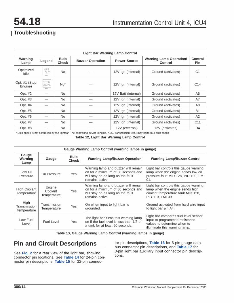
Table 12, Light Bar Warning Lamp Control
Gauge Warning Lamp Control (warning lamps in gauge)
GaugeWarning
LampGauge Bulb
Check Warning Lamp/Buzzer Operation Warning Lamp/Buzzer Control
Low OilPressure Oil Pressure Yes
Warning lamp and buzzer will remainon for a minimum of 30 seconds andwill stay on as long as the faultremains active.
Light bar controls this gauge warninglamp when the engine sends low oilpressure fault MID 128, PID 100, FMI01.
High CoolantTemperature
EngineCoolant
TemperatureYes
Warning lamp and buzzer will remainon for a minimum of 30 seconds andwill stay on as long as the faultremains active.
Light bar controls this gauge warninglamp when the engine sends highcoolant temperature fault MID 128,PID 110, FMI 00.
HighTransmissionTemperature
TransmissionTemperature Yes On when input to light bar is
grounded.Ground activated from hard wire inputto light bar pin A4.
Low FuelLevel Fuel Level Yes
The light bar turns this warning lampon if the fuel level is less than 1/8 ofa tank for at least 60 seconds.
Light bar compares fuel level sensorinput to programmed resistancevalues to determine when toilluminate this warning lamp.
Table 13, Gauge Warning Lamp Control (warning lamps in gauge)
Pin and Circuit DescriptionsSee Fig. 2 for a rear view of the light bar, showingconnector pin locations. See Table 14 for 24-pin con-nector pin descriptions, Table 15 for 32-pin connec-
tor pin descriptions, Table 16 for 6-pin gauge data-bus connector pin descriptions, and Table 17 for3-pin light bar auxiliary input connector pin descrip-tions.
Instrumentation Control Unit 4, ICU454.18Troubleshooting
Columbia Workshop Manual, Supplement 13, December 2005300/14

24-Pin Light Bar Connector Pin Descriptions
Pin Description Pin Description
A1 (+) Panel Backlight Power (PWM)* B1 Optional Warning Lamp # 5—ground activated
A2 Optional Warning Lamp # 6—ground activated B2 (+) Rear Rear Axle Temp Sensor
A3 Low Air Pressure Warning Lamp—groundactivated B3 J1587 databus (–)
A4 High Trans Temp Warning Lamp—groundactivated B4 (–) Rear Rear Axle Temp Sensor
A5 Intake Heater Warning Lamp—ground activated B5 —
A6 Optional Warning Lamp #2—ground activated B6 —
A7 Optional Warning Lamp #3—ground activated B7 —
A8 Optional Warning Lamp #4—ground activated B8 —
A9 No Charge Warning Lamp—ground activated B9 —
A10 (+) Forward Rear Axle Temp Sensor B10 J1587 databus (+)
A11 (–) Forward Rear Axle Temp Sensor B11 Tractor ABS Warning Lamp—ground activated
A12 High Beam Warning Lamp—12V activated B12 Optional Buzzer Input—ground activated* PWM = Pulse Width Modulation
Table 14, 24-Pin Light Bar Connector Pin Descriptions
32-Pin Light Bar Connector Pin Descriptions
Pin Description Pin Description
C1 Optimized Idle Warning Lamp—ground activated D1 (+) Fuel level Sensor
C2 Opt. Low Current Output (gnd)—Starter Lockout D2 (–) Fuel level Sensor
8 7 6 5 4 3 2 1
1 2 2
4 5
f54444307/16/2004
3 3
C16 C1 A12 A1
B1B12D1D1612
34
56
12
34
56
123
1. 3-Pin Auxiliary Input Connector2. 6-Pin Gauge Databus Connector3. Optional Telltale Bulbs
4. 32-Pin Light Bar Connector5. 24-Pin Light Bar Connector
Fig. 2, Light Bar Connector Pin Locations (rear view)
Instrumentation Control Unit 4, ICU4 54.18Troubleshooting
Columbia Workshop Manual, Supplement 13, December 2005 300/15
32-Pin Light Bar Connector Pin Descriptions
Pin Description Pin Description
C3 Opt. Low Current Output (gnd)—KeyIllumination D3 (–) Panel Backlight Ground
C4 Opt. 12V Input (Door Open)* D4 Optional Warning Lamp # 8—12V activated
C5 Park Brake Warning Lamp—ground activated D5 —
C6 (+) Pyrometer D6 (–) Pyrometer
C7 — D7 —
C8 Left Turn Warning Lamp—12V activated D8 Right Turn Warning Lamp—12V activated
C9 — D9 —
C10 Water In Fuel Warning Lamp—ground activated D10 Check Trans Warning Lamp—ground activated
C11 Optional Warning Lamp #7—ground activated D11 —
C12 (–) Sensor common (trans temp, axle #3 temp,ammeter) D12 Trailer ABS Warning Lamp—ground activated
C13 (+) Transmission Oil Temp D13 Ground
C14 Optional Warning Lamp #1—ground activated D14 (+) Battery Power
C15 Check Engine Warning Lamp—ground activated D15 (+) Ignition Power
C16 Engine Protection Warning Lamp—groundactivated D16 (+) Headlamp Power Input 12V—used to control
LCD brightness* Pin C4 (door open input) is used for the Door Open/Park Brake Not Set chime. If the park brake is off, and the door is open, then the light bar will sound a
chime.
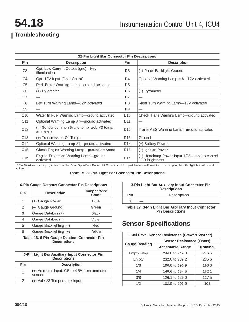
Table 15, 32-Pin Light Bar Connector Pin Descriptions
6-Pin Gauge Databus Connector Pin Descriptions
Pin Description Jumper WireColor
1 (+) Gauge Power Blue
2 (–) Gauge Ground Green
3 Gauge Databus (+) Black
4 Gauge Databus (–) Violet
5 Gauge Backlighting (–) Red
6 Gauge Backlighting (+) Yellow
Table 16, 6-Pin Gauge Databus Connector PinDescriptions
3-Pin Light Bar Auxiliary Input Connector PinDescriptions
Pin Description
1 (+) Ammeter Input, 0.5 to 4.5V from ammetersender
2 (+) Axle #3 Temperature Input
3-Pin Light Bar Auxiliary Input Connector PinDescriptions
Pin Description
3 —
Table 17, 3-Pin Light Bar Auxiliary Input ConnectorPin Descriptions
Sensor Specifications
Fuel Level Sensor Resistance (Stewart-Warner)
Gauge ReadingSensor Resistance (Ohms)
Acceptable Range Nominal
Empty Stop 244.0 to 249.0 246.5
Empty 232.0 to 239.2 235.6
1/8 190.8 to 196.9 193.8
1/4 149.6 to 154.5 152.1
3/8 126.1 to 129.0 127.5
1/2 102.5 to 103.5 103
Instrumentation Control Unit 4, ICU454.18Troubleshooting
Columbia Workshop Manual, Supplement 13, December 2005300/16

Fuel Level Sensor Resistance (Stewart-Warner)
Gauge ReadingSensor Resistance (Ohms)
Acceptable Range Nominal
5/8 84.4 to 85.7 85
3/4 66.2 to 67.8 67
7/8 47.8 to 49.2 48.5
Full 29.4 to 30.6 30
Table 18, Fuel Level Sensor Resistance(Stewart-Warner)
NOTE: If the fuel level sender is below the mini-mum resistance (short to ground) or above themaximum (open), the fuel gauge will readempty. Shorting the sender wires will not testthe gauge circuit.
Transmission Oil Temperature Sensor (Hi-Stat)Resistance, Standard Gauge (°F)
Gauge Temperature (°F) Sensor Resistance (Ohms)
110 4752
150 2079
190 991
230 510
270 285
310 167
350 102
Table 19, Transmission Oil Temperature Sensor (Hi-Stat) Resistance, Standard Gauge
Figure 3 — Transmission Oil Temperature SensorResistance (°F)
Transmission Oil Temperature Sensor (Hi-Stat)Resistance, Metric Gauge (°C)
Gauge Temperature (°C) Sensor Resistance (Ohms)
60 2490
80 1255
100 680
120 390
140 234
160 145
180 95
Table 20, Transmission Oil Temperature Sensor (Hi-Stat) Resistance, Metric Gauge
Figure 4 — Transmission Oil Temperature SensorResistance (°C)
0 1000 2000 3000 4000 5000
Resistance (ohms)
350
310270
230190
150
110
Tem
p (F
°)
08/01/2005 f544444
Fig. 3, Transmission Oil Temperature SensorResistance (°F)
0 500 1000 1500 2000 2500
Resistance (ohms)
180
160140
120100
80
60
Tem
p (°
C)
04/13/2004 f544445
Fig. 4, Transmission Oil Temperature SensorResistance (°C)
Instrumentation Control Unit 4, ICU4 54.18Troubleshooting
Columbia Workshop Manual, Supplement 13, December 2005 300/17

Axle Oil Temperature Sensor (Hi-Stat) Resistance,Standard Gauge (°F)
Gauge Temperature (°F) Sensor Resistance (Ohms)
100 5933
125 3419
150 2079
175 1283
200 837
225 557
250 380
275 267
300 190
Table 21, Axle Oil Temperature Sensor (Hi-Stat)Resistance, Standard Gauge
Figure 5 — Axle Oil Temperature Sensor Resistance(°F)
Axle Oil Temperature Sensor (Hi-Stat) Resistance,Metric Gauge (°C)
Gauge Temperature (°C) Sensor Resistance (Ohms)
30 8060
45 4465
60 2490
75 1503
90 915
105 595
120 390
135 267
Axle Oil Temperature Sensor (Hi-Stat) Resistance,Metric Gauge (°C)
Gauge Temperature (°C) Sensor Resistance (Ohms)
150 185
Table 22, Axle Oil Temperature Sensor (Hi-Stat)Resistance, Metric Gauge
Figure 6 — Axle Oil Temperature Sensor Resistance(°C)
Pyrometer sensors used on initial production use avoltage amplifier. This amplifier supplies a voltagesignal (0.45V to 6.7V) to the instrument cluster.
Pyrometer Sensor (with voltage amplifier)
ThermocoupleTemperature (°F) Input (millivolts) Output (Volts)
300 5.0 0.46
360 6.4 0.75
420 7.6 1.05
480 9.0 1.35
540 10.4 1.66
600 11.9 1.96
660 13.2 2.28
720 14.6 2.59
780 16.2 2.90
840 17.6 3.22
900 18.8 3.54
960 20.3 3.85
1020 21.8 4.17
1080 23.2 4.48
0 1000 2000 3000 4000 5000
Resistance (ohms)
250225200175150125100
Tem
p (°
F)
04/13/2004 f544446
6000
300275
Fig. 5, Axle Oil Temperature Sensor Resistance (°F)
0 2000 4000
Resistance (ohms)
1201059075604530
Tem
p (°
C)
04/13/2004 f544450
6000 8000
135150
Fig. 6, Axle Oil Temperature Sensor Resistance (°C)
Instrumentation Control Unit 4, ICU454.18Troubleshooting
Columbia Workshop Manual, Supplement 13, December 2005300/18

Pyrometer Sensor (with voltage amplifier)
ThermocoupleTemperature (°F) Input (millivolts) Output (Volts)
1140 24.5 4.81
1200 25.9 5.12
1260 27.3 5.44
1320 28.6 5.75
1380 30.0 6.06
1440 31.5 6.37
1500 32.8 6.68
Table 23, Pyrometer Sensor (with voltage amplifier)
InPower Hall-Effect Current Sensor (DCS25; ammetersensor)
Amps (Gauge) Sensor Output (Volts)
–300 0.5
–100 1.833
–75 2.0
–50 2.166
–25 2.333
0 2.5
25 2.666
50 2.833
75 3.0
100 3.166
300 4.5
Table 24, InPower Hall-Effect Current Sensor (DCS25;ammeter sensor)
Figure 7 — Ammeter Current Sensor Wiring Dia-gram (InPower)
Figure 8 — Ammeter Current Sensor Output Voltage(–300 to +300 Amp Range)
Figure 9 — Ammeter Current Sensor Output Voltage(–100 to +100 Amp Range)
04/13/2004 f544440
1
2
3
4
1. Ground2. DCS25 Current Sensor3. Battery4. Instrument Cluster Light Bar
Fig. 7, Ammeter Current Sensor Wiring Diagram(InPower)
0.0 1.0 2.0 3.0 4.0 5.0
Output (Volts)
300
200100
0−100−200−300
Gau
ge C
urre
nt (
Am
ps)
04/13/2004 f544441
Fig. 8, Ammeter Current Sensor Output Voltage (–300to +300 Amp Range)
Instrumentation Control Unit 4, ICU4 54.18Troubleshooting
Columbia Workshop Manual, Supplement 13, December 2005 300/19

1.5 2.0 2.5 3.0 3.5
Output (Volts)
100
50
0
−50
−100
Gau
ge C
urre
nt (
Am
ps)
04/13/2004 f544442
Fig. 9, Ammeter Current Sensor Output Voltage (–100to +100 Amp Range)
Instrumentation Control Unit 4, ICU454.18Troubleshooting
Columbia Workshop Manual, Supplement 13, December 2005300/20

Pin and Circuit DescriptionsSee Fig. 1 for a rear view of the light bar, showingconnector pin locations. See Table 1 for 24-pin con-nector pin descriptions, Table 2 for 32-pin connectorpin descriptions, Table 3 for 6-pin gauge databusconnector pin descriptions, and Table 4 for 3-pin lightbar auxiliary input connector pin descriptions.
24-Pin Light Bar Connector Pin Descriptions
Pin Description Pin Description
A1 (+) Panel Backlight Power (PWM)* B1 Optional Warning Lamp # 5—ground activated
A2 Optional Warning Lamp # 6—ground activated B2 (+) Rear Rear Axle Temp Sensor
A3 Low Air Pressure Warning Lamp—groundactivated B3 J1587 databus (–)
A4 High Trans Temp Warning Lamp—groundactivated B4 (–) Rear Rear Axle Temp Sensor
A5 Intake Heater Warning Lamp—ground activated B5 —
A6 Optional Warning Lamp #2—ground activated B6 —
A7 Optional Warning Lamp #3—ground activated B7 —
A8 Optional Warning Lamp #4—ground activated B8 —
A9 No Charge Warning Lamp—ground activated B9 —
A10 (+) Forward Rear Axle Temp Sensor B10 J1587 databus (+)
A11 (–) Forward Rear Axle Temp Sensor B11 Tractor ABS Warning Lamp—ground activated
8 7 6 5 4 3 2 1
1 2 2
4 5
f54444307/16/2004
3 3
C16 C1 A12 A1
B1B12D1D1612
34
56
12
34
56
123
1. 3-Pin Auxiliary Input Connector2. 6-Pin Gauge Databus Connector3. Optional Telltale Bulbs
4. 32-Pin Light Bar Connector5. 24-Pin Light Bar Connector
Fig. 1, Light Bar Connector Pin Locations (rear view)
Instrumentation Control Unit 4, ICU4 54.18Specifications
Columbia Workshop Manual, Supplement 6, September 2004 400/1

24-Pin Light Bar Connector Pin Descriptions
Pin Description Pin Description
A12 High Beam Warning Lamp—12V activated B12 Optional Buzzer Input—ground activated* PWM = Pulse Width Modulation
Table 1, 24-Pin Light Bar Connector Pin Descriptions
32-Pin Light Bar Connector Pin Descriptions
Pin Description Pin Description
C1 Optimized Idle Warning Lamp—ground activated D1 (+) Fuel level Sensor
C2 Opt. Low Current Output (gnd)—Starter Lockout D2 (–) Fuel level Sensor
C3 Opt. Low Current Output (gnd)—KeyIllumination D3 (–) Panel Backlight Ground
C4 Opt. 12V Input (Door Open)* D4 Optional Warning Lamp # 8—12V activated
C5 Park Brake Warning Lamp—ground activated D5 —
C6 (+) Pyrometer D6 (–) Pyrometer
C7 — D7 —
C8 Left Turn Warning Lamp—12V activated D8 Right Turn Warning Lamp—12V activated
C9 — D9 —
C10 Water In Fuel Warning Lamp—ground activated D10 Check Trans Warning Lamp—ground activated
C11 Optional Warning Lamp #7—ground activated D11 —
C12 (–) Sensor common (trans temp, axle #3 temp,ammeter) D12 Trailer ABS Warning Lamp—ground activated
C13 (+) Transmission Oil Temp D13 Ground
C14 Optional Warning Lamp #1—ground activated D14 (+) Battery Power
C15 Check Engine Warning Lamp—ground activated D15 (+) Ignition Power
C16 Engine Protection Warning Lamp—groundactivated D16 (+) Headlamp Power Input 12V—used to control
LCD brightness* Pin C4 (door open input) is used for the Door Open/Park Brake Not Set chime. If the park brake is off, and the door is open, then the light bar will sound a
chime.
Table 2, 32-Pin Light Bar Connector Pin Descriptions
6-Pin Gauge Databus Connector Pin Descriptions
Pin Description Jumper WireColor
1 (+) Gauge Power Blue
2 (–) Gauge Ground Green
3 Gauge Databus (+) Black
4 Gauge Databus (–) Violet
5 Gauge Backlighting (–) Red
6-Pin Gauge Databus Connector Pin Descriptions
Pin Description Jumper WireColor
6 Gauge Backlighting (+) Yellow
Table 3, 6-Pin Gauge Databus Connector PinDescriptions
Instrumentation Control Unit 4, ICU454.18Specifications
Columbia Workshop Manual, Supplement 6, September 2004400/2

3-Pin Light Bar Auxiliary Input Connector PinDescriptions
Pin Description
1 (+) Ammeter Input, 0.5 to 4.5V from ammetersender
2 (+) Axle #3 Temperature Input
3 —
Table 4, 3-Pin Light Bar Auxiliary Input Connector PinDescriptions
Instrumentation Control Unit 4, ICU4 54.18Specifications
Columbia Workshop Manual, Supplement 6, September 2004 400/3

General InformationThe mode/reset switch controls the display of theodometer, trip miles and hours, engine miles andhours, service cycle screens, fault code screens, andoil level screens (on some Mercedes engines; ifequipped and enabled).
Push the switch to scroll through mode selections,and hold the switch to reset trip miles or hours whilethey are displayed. See Fig. 1 . With the parkingbrake released, only the odometer, trip miles, and triphours can be accessed. Park the vehicle and set theparking brake to access additional screen functions.See Fig. 2 and Fig. 3 .
Trip Miles, Trip HoursWhen the odometer is displayed, push the mode/reset switch once to display trip distance. Push itagain to display trip hours. Both numbers are calcu-lated from the last time the value was reset. Hold theswitch when each number is displayed to reset tripmiles or hours to zero.
Diagnostic ScreensDuring vehicle start-up, with the parking brake on,the ICU4 displays any active fault codes for threeseconds each until the parking brake is released.With active fault codes on display, push the mode/reset switch once to display the initial diagnosticscreen (DIAG) and the total number of active faults.If service cycle screens are enabled, and service dis-tance or time has been exceeded, the text SERVICEwill be displayed with the other fault messages. Thiswill inform the vehicle operator that the service inter-val has been exceeded and vehicle service is re-quired.
Specific fault code information can be displayed onlywith the vehicle parked and the parking brake set. Ifthe odometer screen is displayed, push the mode/reset switch until the DIAG screen is displayed, thenhold the switch to enter the fault code screen se-quence. Once the initial fault code is displayed, pushthe switch to cycle through additional diagnosticcodes relating to the first fault. Hold the switch to dis-play additional faults or return to the DIAG screen. Ifservice cycle screens are enabled, service intervalinformation is displayed before fault code informationis displayed.
If the word SERVICE appears on the DIAG messagedisplay screen, service cycle screens are enabled.Hold the mode/reset switch at the DIAG screen todisplay miles or hours remaining until the next sched-uled service. If MI appears on the DIAG screen, ser-vice miles are enabled; if HOURS appears on thescreen, service hours are enabled. Either servicemiles or hours can be enabled, but not both. If ser-vice miles or hours has been exceeded, the numberflashes to indicate service is overdue.
Engine ScreensPush the mode/reset switch once following the DIAGscreen and the word ENGINE is displayed in thelower right corner of the digital display. Hold theswitch to display total engine miles. Hold it again todisplay total engine hours. If OIL LVL is displayedearlier with ENGINE (on Mercedes vehicles only; ifequipped and enabled) hold the switch again to ac-cess oil level screens.
Oil Level Screens (optional)If OIL LVL is displayed with ENGINE, hold the switchtwice to display total engine miles and total enginehours, respectively, then hold again to access oillevel screens.
The display will read OIL OK, or it will display OILLVL and indicate in the lower left hand corner of thedisplay whether the level is high (HI) or low (Lo).Hold the switch again to display the amount, inquarts (QTS) or liters (LTS), by which the oil level ishigh or low. If the oil level is low or OK the amountwill be displayed with a minus sign in front of it (–). Ifthe oil level is high the amount will be displayed as awhole number. If the oil level is OK, the level will dis-play -0 QTS (quarts) or -0 LTS (liters).
The maximum range of quarts or liters too low orhigh is from –9 to 9.
Hold the button again to return to the OIL LVL/ENGINE screen, or push the button to go to theSETUP screen.
If the engine oil level message is not received fromthe engine for 25 seconds, the text Lo, HI, or blankdisplays as hyphens (- -) while the OIL LVL text ap-pears on the display. The hyphens indicate that theengine oil level message communication was re-ceived at one time, but now has a problem. The en-
Instrumentation Control Unit 4, ICU4 54.18Mode/Reset Switch Functions
Columbia Workshop Manual, Supplement 12, June 2005 410/1

gine oil amount screen will not be displayed if the oillevel message is not received.
To change units of measure between quarts and li-ters, go to the the SETUP display screen, hold theswitch to advance to the SELECT screen, then holdagain to toggle between MI (miles) and KM (kilome-ters). When set to miles the oil level amount screenswill display the unit of measure in quarts (U.S. cus-tomary). When set to kilometers the amount screenswill display liters (metric).
Setup ScreensSetup screens allow the technician to:
• Change between U.S. customary and metricunits
• Turn the LCD display lamp on and off
• Set a service interval to miles or hours, or turnit off
• Reset service interval counters
• Set service interval values
See Fig. 3 for a flowchart of the setup screens.
Service Interval TablesFor service interval miles look-up values, seeTable 1 .
For service interval hours look-up values, seeTable 2 .
f040693
Push
With
par
k br
ake
off
Go to the Diagnostic and Engine Display Screens figure.
Hold
If "SERVICE" is displayed Service Cycle screens are enabled and either "MI" or "HOURS" is also displayed.
On some vehicles "OIL LVL" appears in the top row of the display, if equipped and enabled.
Default OdometerDisplay Screen
To Reset Trip Miles
To Reset Trip Hours
Hold
Hold
Hold
Push
Push
Push
Push
Push
Hold For setup screens.
Go to the Diagnostic and Engine Display Screens figure.
With park brake on
06/01/2004
Fig. 1, Mode/Reset Switch Basic Functions
Instrumentation Control Unit 4, ICU454.18Mode/Reset Switch Functions
Columbia Workshop Manual, Supplement 12, June 2005410/2

Service Interval Distance Settings
Number Miles Kilometers
1 1000 1610
2 1500 2415
3 2000 3220
4 2500 4025
5 3000 4830
6 3500 5635
7 4000 6440
8 4500 7245
9 5000 8050
10 5500 8855
11 6000 9660
12 6500 10465
13 7000 11270
14 7500 12075
Service Interval Distance Settings
Number Miles Kilometers
15 8000 12880
16 8500 13685
17 9000 14490
18 9500 15295
19 10000 16100
20 11000 17710
21 12000 19320
22 13000 20930
23 14000 22540
24 15000 24150
25 16000 25760
26 17000 27370
27 18000 28980
28 19000 30590
To display totalengine miles.
To display tolalengine hours.
To display OIL LVLscreens (if equippedand enabled).
To display specific OIL LVL amountover or under full.
For additional faults,if any, or return toDIAG screen.
04/28/2004 f040695
Push
Hold
Push
Push
Push
Hold
Hold
Hold
Push
HoldHold
Hold
Push
Then
If "SERVICE" is displayed Service Cycle screens are enabled and either "MI" or "HOURS" is also displayed.
On some vehicles "OIL LVL" appears in the top row of the display, if equipped and enabled.
Service Cycle Screens (if enabled): Holding the button displays Service Miles or Service Hours, remaining or exceeded, to service target. If numbers flash, the service target is exceeded and service is overdue. Also, the "SERVICE" screen will be displayed as an active Fault Code when service miles or hours are ex−ceeded.
If Service Cycle screens not enabled
Or
Fig. 2, Mode/Reset Switch Diagnostic and Engine Display Screens
Instrumentation Control Unit 4, ICU4 54.18Mode/Reset Switch Functions
Columbia Workshop Manual, Supplement 12, June 2005 410/3

Service Interval Distance Settings
Number Miles Kilometers
29 20000 32200
30 21000 33810
31 22000 35420
32 23000 37030
33 24000 38640
34 25000 40250
Table 1, Service Interval Distance Settings
Service Interval Hours Settings
Number Hours
1 50
2 75
3 100
4 125
5 150
6 175
7 200
8 225
9 250
10 300
11 350
12 400
13 450
14 500
15 550
16 600
17 650
18 700
19 750
20 800
21 850
22 900
23 950
24 1000
Table 2, Service Interval Hours Settings
Instrumentation Control Unit 4, ICU454.18Mode/Reset Switch Functions
Columbia Workshop Manual, Supplement 12, June 2005410/4

Hold
Push
To Toggle Between Units
ON <−−> OFF
MI <−−> KM
Flash Screen Text
To Toggle Between Units
Flash Screen Text
Displayactive mode
Metric versionScreen are similar to
English versionscreens
Hold willreset allService Intervalcounters
To Toggle BetweenMI −−>HOURS−−>no−−>
To Toggle BetweenLook−up Table
hours
To Toggle BetweenLook−up Table
Miles
Flash Screen Text
Flash Screen TextThe no selection will disable
the Service Interval
Selection?
MI
no HOURS
07/09/2004
Push Push
Push
Push
Push
Push
HoldHold
Hold
Hold
Hold
Flash Screen Text
f040697
Default OdometerDisplay Screen
Hold
Hold
Push
Fig. 3, Mode/Reset Switch Setup Screens
Instrumentation Control Unit 4, ICU4 54.18Mode/Reset Switch Functions
Columbia Workshop Manual, Supplement 12, June 2005 410/5
