general 6shfl¿fdwlrqv dnp3 communication portfoliol dnp3 communication portfolio dnp3 communication...
TRANSCRIPT

GeneralSpecifications
<<Contents>> <<Index>>
DNP3 Communication Portfolio
Yokogawa Electric Corporation2-9-32, Nakacho, Musashino-shi, Tokyo, 180-8750 JapanTel.: 81-422-52-5616 URL: http://www.stardom.biz
GS 34P02P22-01E
GS 34P02P22-01E©Copyright Jan. 2006(YK)
12th Edition Feb. 28, 2014(YK)
GENERALThis General Specifications document describes the Distributed Network Protocol (DNP3) Communication Portfolio for STARDOM. The DNP3 Communication Portfolio generates a control application for FCN/FCJ autonomous controllers. Using this portfolio, the FCN/FCJ can perform DNP3 communication via a serial port or Ethernet port.
OPERATING ENVIRONMENTl FCN (Except FCN-RTU)
Communication type Communication port
Serial communicationRS-232-C
CPU module (NFCP100) Serial port (*1)
Serial communication module (NFLR111) Serial port
RS-422/RS-485 Serial communication module (NFLR121) Serial port
Ethernet communication CPU module (NFCP100) Ethernet port
*1: InaCPUduplexconfiguration,theCPUmoduleserialportcannotbeused.
l FCN-RTU
Communication type Communication port
Serial communicationRS-232-C CPU module (NFCP050) Serial port
RS-422/RS-485 CPU module (NFCP050) Serial port
Ethernet communication CPU module (NFCP050) Ethernet port
l FCJ
Communication type Communication port
Serial communication RS-232-C Serial port
Ethernet communication Ethernet port

2
All Rights Reserved. Copyright © 2006, Yokogawa Electric Corporation
<<Contents>> <<Index>>
GS 34P02P22-01E
FUNCTION SPECIFICATIONSl DNP3 Communication PortfolioDNP3 Communication Portfolio is a POU that enables DNP3 communication protocol support devices to easily acquire data from FCN/FCJ autonomous controllers via serial communication or Ethernet communication. The following communication functions are supported:
Communication type (*3) (*4) Communication function
Serial communication (*1) SlaveUp to two ports can be communicated
Ethernet communication (*2) ServerUp to two client can be connected
*1: Serial communication is possible only when the FCN/FCJ operates as a slave.*2: FCN/FCJ operates as a server.*3: Only one of these communications can be used.*4: InaCPUduplexconfiguration,allchangeeventswillberesetatCPUswitch-over.
T01E.ai
DNP3 Communication Device
FCN/FCJ
ReadingControl
ApplicationWriting
DNP3 DataVariable Area
Serial communication orEthernet communication
Dat
a A
cqui
sitio
n
Out
put O
pera
tion
Figure DNP3 Data Access
Feb. 28, 2013-00
3<<Contents>> <<Index>>
All Rights Reserved. Copyright © 2006, Yokogawa Electric Corporation GS 34P02P22-01E May 31, 2012-00
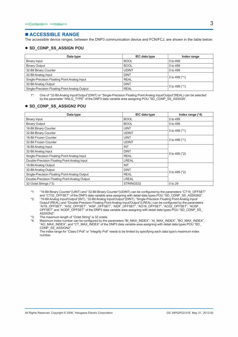
ACCESSIBLE RANGEThe accessible device ranges, between the DNP3 communication device and FCN/FCJ, are shown in the table below:
l SD_CDNP_SS_ASSIGN POU
Data type IEC data type Index rangeBinary Input BOOL 0 to 499Binary Output BOOL 0 to 49932-Bit Binary Counter UDINT 0 to 49932-Bit Analog Input DINT
0 to 499 (*1)Single-Precision Floating Point Analog Input REAL 32-Bit Analog Output DINT
0 to 499 (*1)Single-Precision Floating Point Analog Output REAL
1*: One of “32-Bit Analog Input/Output”(DINT) or “Single-Precision Floating Point Analog Input/Output”(REAL) can be selected by the parameter “ANLG_TYPE” of the DNP3 data variable area assigning POU ”SD_CDNP_SS_ASSIGN”.
l SD_CDNP_SS_ASSIGN2 POU
Data type IEC data type Index range (*4)Binary Input BOOL 0 to 499Binary Output BOOL 0 to 49916-Bit Binary Counter UINT
0 to 499 (*1)32-Bit Binary Counter UDINT16-Bit Frozen Counter UINT
0 to 499 (*1)32-Bit Frozen Counter UDINT16-Bit Analog Input INT
0 to 499 (*2)32-Bit Analog Input DINT Single-Precision Floating Point Analog Input REAL Double-Precision Floating Point Analog Input LREAL 16-Bit Analog Output INT
0 to 499 (*2)32-Bit Analog Output DINT Single-Precision Floating Point Analog Output REAL Double-Precision Floating Point Analog Output LREAL 32-Octet Strings (*3) STRINGS32 0 to 29
*1: “16-Bit Binary Counter”(UINT) and “32-Bit Binary Counter”(UDINT) can be configured by the parameters “CT16_OFFSET” and “CT32_OFFSET” of the DNP3 data variable area assigning with detail data types POU “SD_CDNP_SS_ASSIGN2”.
*2: “16-Bit Analog Input/Output”(INT), “32-Bit Analog Input/Output”(DINT), “Single-Precision Floating Point Analog Input/Output”(REAL) and “Double-Precision Floating Point Analog Input/Output”(LREAL) can be configured by the parameters “AI16_OFFSET”, “AI32_OFFSET”, “AISF_OFFSET”, “AIDF_OFFSET”, “AO16_OFFSET”, “AO32_OFFSET”, “AOSF_OFFSET” and “AODF_OFFSET” of the DNP3 data variable area assigning with detail data types POU “SD_CDNP_SS_ASSIGN2”.
*3: The maximum length of “Octet String” is 32 octets.*4: Maximum index number can be configured by the parameters “BI_MAX_INDEX”, “AI_MAX_INDEX”, “BO_MAX_INDEX”,
“AO_MAX_INDEX”, and “CT_MAX_INDEX” of the DNP3 data variable area assigning with detail data types POU “SD_CDNP_SS_ASSIGN2”. The index range for “Class 0 Poll” or “Integrity Poll” needs to be limited by specifying each data type’s maximum index number.

4
All Rights Reserved. Copyright © 2006, Yokogawa Electric Corporation
<<Contents>> <<Index>>
GS 34P02P22-01E
LIST OF POU FUNCTIONSl DNP3 Communicaton POUThetablebelowpresentsPOUsthataredefinedtostartDNP3communication:
POU name Function SD_CDNP_SS_ASSIGN AssigningdatavariablestoaspecificmemorySD_CDNP_SS_ASSIGN2 AssigningdatavariablestoaspecificmemorywithdetaildatatypesSD_CDNP_SS_RS_ OPEN Starting DNP3 communication task for serial communication SD_CDNP_SS_TCP_ OPEN Starting DNP3 communication task for Ethernet communication
l Data Attribute POUThetablebelowpresentsPOUsthataredefinedtoassignattributesforindividualdatavariables:
POU name FunctionSD_CDNP_S_EVTC Assigning event class
SD_CDNP_S_DBND Setting analog input deadband value
SD_CDNP_S_DBND_AO_LOCAL Setting analog output local operation deadband value
SD_CDNP_S_CROB Setting binary output operation attribute
l Data Access POUThe table below presents POUs that are used to access various data variables:
POU name Function SD_CDNP_S_BI_RD Reading binary input data SD_CDNP_S_BO_RD Reading binary output data SD_CDNP_S_CT16_RD Reading 16-bit binary counter dataSD_CDNP_S_CT32_RD Reading 32-bit binary counter data SD_CDNP_S_AI16_RD Reading 16-bit analog input dataSD_CDNP_S_AI32_RD Reading 32-bit analog input data SD_CDNP_S_AISF_RD Readingsingle-precisionfloatingpointanaloginputdataSD_CDNP_S_AIDF_RD Readingdouble-precisionfloatingpointanaloginputdataSD_CDNP_S_AO16_RD Reading16-bit analog output dataSD_CDNP_S_AO32_RD Reading 32-bit analog output data SD_CDNP_S_AOSF_RD Readingsingle-precisionfloatingpointanalogoutputdataSD_CDNP_S_AODF_RD Readingdouble-precisionfloatingpointanalogoutputdataSD_CDNP_S_OSTR32_RD Reading 32-octet string dataSD_CDNP_S_BI_WT Writing binary input data SD_CDNP_S_BO_WT Writing binary output data SD_CDNP_S_CT16_WT Writing 16-bit binary counter dataSD_CDNP_S_CT32_WT Writing 32-bit binary counter data SD_CDNP_S_AI16_WT Writing 16-bit analog input dataSD_CDNP_S_AI32_WT Writing 32-bit analog input data SD_CDNP_S_AISF_WT Writingsingle-precisionfloatingpointanaloginputdataSD_CDNP_S_AIDF_WT Writingdouble-precisionfloatingpointanaloginputdataSD_CDNP_S_AO16_WT Writing 16-bit analog output dataSD_CDNP_S_AO32_WT Writing 32-bit analog output data SD_CDNP_S_AOSF_WT Writingsingle-precisionfloatingpointanalogoutputdataSD_CDNP_S_AODF_WT Writingdouble-precisionfloatingpointanalogoutputdataSD_DCNP_S_OSTR32_WT Writing 32-octet string data
l Command Execution POU
POU name Function SD_CDNP_S_CROB_PULSE Executing binary output pulse model command operation
Feb. 28, 2013-00
5<<Contents>> <<Index>>
All Rights Reserved. Copyright © 2006, Yokogawa Electric Corporation GS 34P02P22-01E Feb. 28, 2013-00
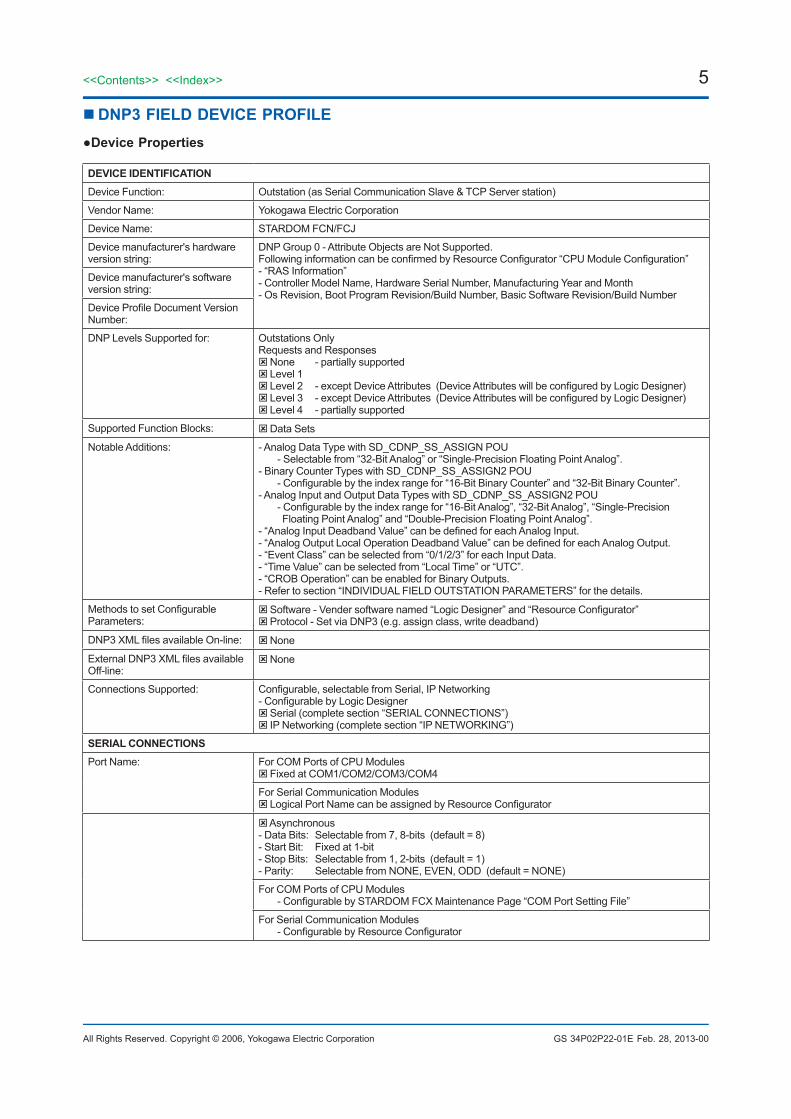
DNP3 FIELD DEVICE PROFILE●Device Properties
DEVICE IDENTIFICATIONDevice Function: Outstation (as Serial Communication Slave & TCP Server station)
Vendor Name: Yokogawa Electric Corporation
Device Name: STARDOM FCN/FCJ
Device manufacturer's hardware version string:
DNP Group 0 - Attribute Objects are Not Supported.FollowinginformationcanbeconfirmedbyResourceConfigurator“CPUModuleConfiguration”- “RAS Information”- Controller Model Name, Hardware Serial Number, Manufacturing Year and Month- Os Revision, Boot Program Revision/Build Number, Basic Software Revision/Build Number
Device manufacturer's software version string:
DeviceProfileDocumentVersionNumber:
DNP Levels Supported for: Outstations Only Requests and Responses None - partially supported Level 1 Level2 -exceptDeviceAttributes(DeviceAttributeswillbeconfiguredbyLogicDesigner)Level3 -exceptDeviceAttributes(DeviceAttributeswillbeconfiguredbyLogicDesigner) Level 4 - partially supported
Supported Function Blocks: Data Sets
Notable Additions: - Analog Data Type with SD_CDNP_SS_ASSIGN POU - Selectable from “32-Bit Analog” or “Single-Precision Floating Point Analog”.- Binary Counter Types with SD_CDNP_SS_ASSIGN2 POU -Configurablebytheindexrangefor“16-BitBinaryCounter”and“32-BitBinaryCounter”.- Analog Input and Output Data Types with SD_CDNP_SS_ASSIGN2 POU -Configurablebytheindexrangefor“16-BitAnalog”,“32-BitAnalog”,“Single-Precision Floating Point Analog” and “Double-Precision Floating Point Analog”.-“AnalogInputDeadbandValue”canbedefinedforeachAnalogInput.-“AnalogOutputLocalOperationDeadbandValue”canbedefinedforeachAnalogOutput.- “Event Class” can be selected from “0/1/2/3” for each Input Data.- “Time Value” can be selected from “Local Time” or “UTC”.- “CROB Operation” can be enabled for Binary Outputs.- Refer to section “INDIVIDUAL FIELD OUTSTATION PARAMETERS” for the details.
MethodstosetConfigurableParameters:
Software-Vendersoftwarenamed“LogicDesigner”and“ResourceConfigurator” Protocol - Set via DNP3 (e.g. assign class, write deadband)
DNP3XMLfilesavailableOn-line: None
ExternalDNP3XMLfilesavailableOff-line:
None
Connections Supported: Configurable,selectablefromSerial,IPNetworking-ConfigurablebyLogicDesigner Serial (complete section “SERIAL CONNECTIONS”) IP Networking (complete section “IP NETWORKING”)
SERIAL CONNECTIONSPort Name: For COM Ports of CPU Modules
Fixed at COM1/COM2/COM3/COM4
For Serial Communication ModulesLogicalPortNamecanbeassignedbyResourceConfigurator
Asynchronous- Data Bits: Selectable from 7, 8-bits (default = 8)- Start Bit: Fixed at 1-bit- Stop Bits: Selectable from 1, 2-bits (default = 1)- Parity: Selectable from NONE, EVEN, ODD (default = NONE)
For COM Ports of CPU Modules -ConfigurablebySTARDOMFCXMaintenancePage“COMPortSettingFile”
For Serial Communication Modules -ConfigurablebyResourceConfigurator
6
All Rights Reserved. Copyright © 2006, Yokogawa Electric Corporation
<<Contents>> <<Index>>
GS 34P02P22-01E
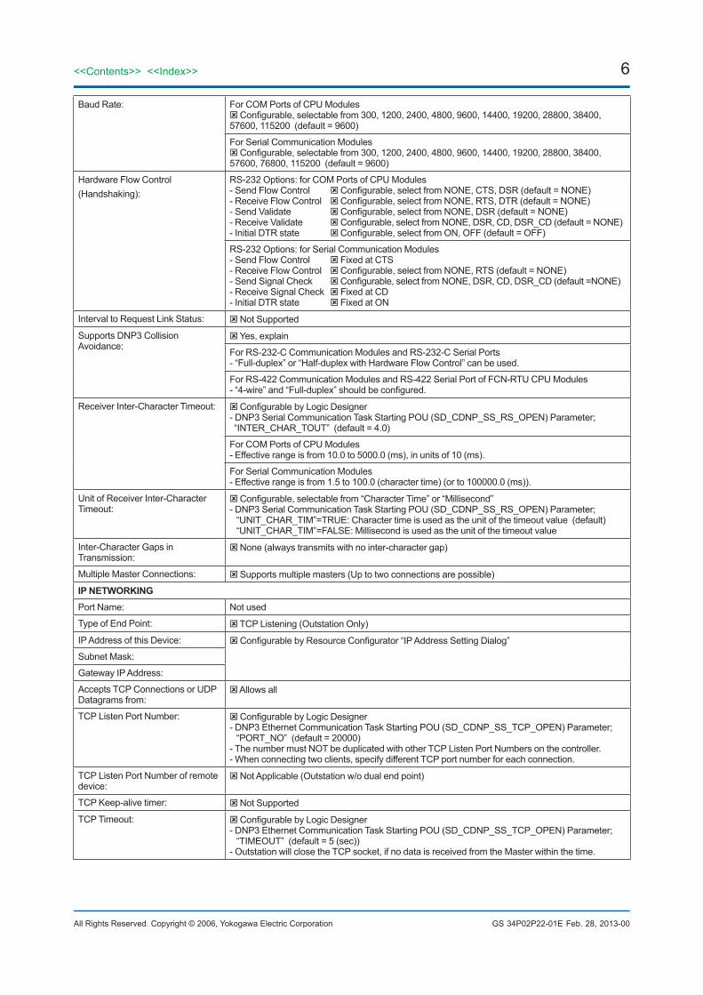
Baud Rate: For COM Ports of CPU ModulesConfigurable,selectablefrom300,1200,2400,4800,9600,14400,19200,28800,38400,57600, 115200 (default = 9600)
For Serial Communication ModulesConfigurable,selectablefrom300,1200,2400,4800,9600,14400,19200,28800,38400,57600, 76800, 115200 (default = 9600)
Hardware Flow Control (Handshaking):
RS-232 Options: for COM Ports of CPU Modules- Send Flow Control Configurable,selectfromNONE,CTS,DSR(default=NONE)- Receive Flow Control Configurable,selectfromNONE,RTS,DTR(default=NONE)- Send Validate Configurable,selectfromNONE,DSR(default=NONE)- Receive Validate Configurable,selectfromNONE,DSR,CD,DSR_CD(default=NONE)- Initial DTR state Configurable,selectfromON,OFF(default=OFF)
RS-232 Options: for Serial Communication Modules- Send Flow Control Fixed at CTS- Receive Flow Control Configurable,selectfromNONE,RTS(default=NONE)- Send Signal Check Configurable,selectfromNONE,DSR,CD,DSR_CD(default=NONE)- Receive Signal Check Fixed at CD- Initial DTR state Fixed at ON
Interval to Request Link Status: Not Supported
Supports DNP3 Collision Avoidance:
Yes, explain
For RS-232-C Communication Modules and RS-232-C Serial Ports- “Full-duplex” or “Half-duplex with Hardware Flow Control” can be used.
For RS-422 Communication Modules and RS-422 Serial Port of FCN-RTU CPU Modules-“4-wire”and“Full-duplex”shouldbeconfigured.
Receiver Inter-Character Timeout: ConfigurablebyLogicDesigner- DNP3 Serial Communication Task Starting POU (SD_CDNP_SS_RS_OPEN) Parameter; “INTER_CHAR_TOUT” (default = 4.0)
For COM Ports of CPU Modules- Effective range is from 10.0 to 5000.0 (ms), in units of 10 (ms).
For Serial Communication Modules- Effective range is from 1.5 to 100.0 (character time) (or to 100000.0 (ms)).
Unit of Receiver Inter-Character Timeout:
Configurable,selectablefrom“CharacterTime”or“Millisecond”- DNP3 Serial Communication Task Starting POU (SD_CDNP_SS_RS_OPEN) Parameter; “UNIT_CHAR_TIM”=TRUE: Character time is used as the unit of the timeout value (default) “UNIT_CHAR_TIM”=FALSE: Millisecond is used as the unit of the timeout value
Inter-Character Gaps in Transmission:
None (always transmits with no inter-character gap)
Multiple Master Connections: Supports multiple masters (Up to two connections are possible)
IP NETWORKINGPort Name: Not used
Type of End Point: TCP Listening (Outstation Only)
IP Address of this Device: ConfigurablebyResourceConfigurator“IPAddressSettingDialog”
Subnet Mask:
Gateway IP Address:
Accepts TCP Connections or UDP Datagrams from:
Allows all
TCP Listen Port Number: ConfigurablebyLogicDesigner- DNP3 Ethernet Communication Task Starting POU (SD_CDNP_SS_TCP_OPEN) Parameter; “PORT_NO” (default = 20000)- The number must NOT be duplicated with other TCP Listen Port Numbers on the controller.- When connecting two clients, specify different TCP port number for each connection.
TCP Listen Port Number of remote device:
Not Applicable (Outstation w/o dual end point)
TCP Keep-alive timer: Not Supported
TCP Timeout: ConfigurablebyLogicDesigner- DNP3 Ethernet Communication Task Starting POU (SD_CDNP_SS_TCP_OPEN) Parameter; “TIMEOUT” (default = 5 (sec))- Outstation will close the TCP socket, if no data is received from the Master within the time.
Feb. 28, 2013-00
7<<Contents>> <<Index>>
All Rights Reserved. Copyright © 2006, Yokogawa Electric Corporation GS 34P02P22-01E Feb. 28, 2013-00
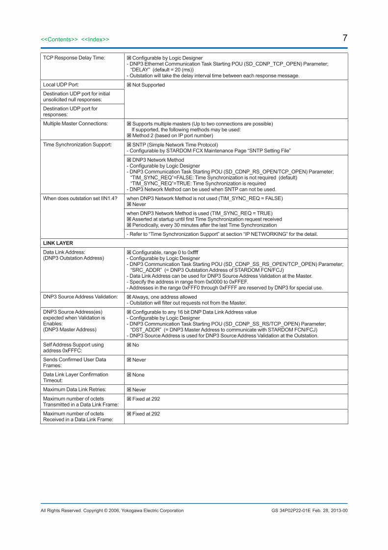
TCP Response Delay Time: ConfigurablebyLogicDesigner- DNP3 Ethernet Communication Task Starting POU (SD_CDNP_TCP_OPEN) Parameter; “DELAY” (default = 20 (ms))- Outstation will take the delay interval time between each response message.
Local UDP Port: Not Supported
Destination UDP port for initial unsolicited null responses:
Destination UDP port for responses:
Multiple Master Connections: Supports multiple masters (Up to two connections are possible) If supported, the following methods may be used: Method 2 (based on IP port number)
Time Synchronization Support: SNTP (Simple Network Time Protocol)-ConfigurablebySTARDOMFCXMaintenancePage“SNTPSettingFile”
DNP3 Network Method-ConfigurablebyLogicDesigner- DNP3 Communication Task Starting POU (SD_CDNP_RS_OPEN/TCP_OPEN) Parameter; “TIM_SYNC_REQ”=FALSE: Time Synchronization is not required (default) “TIM_SYNC_REQ”=TRUE: Time Synchronization is required- DNP3 Network Method can be used when SNTP can not be used.
When does outstation set IIN1.4? when DNP3 Network Method is not used (TIM_SYNC_REQ = FALSE) Never
when DNP3 Network Method is used (TIM_SYNC_REQ = TRUE)AssertedatstartupuntilfirstTimeSynchronizationrequestreceived Periodically, every 30 minutes after the last Time Synchronization
- Refer to “Time Synchronization Support” at section “IP NETWORKING” for the detail.
LINK LAYERData Link Address:(DNP3 Outstation Address)
Configurable,range0to0xffff-ConfigurablebyLogicDesigner- DNP3 Communication Task Starting POU (SD_CDNP_SS_RS_OPEN/TCP_OPEN) Parameter; “SRC_ADDR” (= DNP3 Outstation Address of STARDOM FCN/FCJ)- Data Link Address can be used for DNP3 Source Address Validation at the Master.- Specify the address in range from 0x0000 to 0xFFEF.- Addresses in the range 0xFFF0 through 0xFFFF are reserved by DNP3 for special use.
DNP3 Source Address Validation: Always, one address allowed-OutstationwillfilteroutrequestsnotfromtheMaster.
DNP3 Source Address(es) expected when Validation is Enables:(DNP3 Master Address)
Configurabletoany16bitDNPDataLinkAddressvalue-ConfigurablebyLogicDesigner- DNP3 Communication Task Starting POU (SD_CDNP_SS_RS/TCP_OPEN) Parameter; “DST_ADDR” (= DNP3 Master Address to communicate with STARDOM FCN/FCJ)- DNP3 Source Address is used for DNP3 Source Address Validation at the Outstation.
Self Address Support using address 0xFFFC:
No
SendsConfirmedUserDataFrames:
Never
DataLinkLayerConfirmationTimeout:
None
Maximum Data Link Retries: Never
Maximum number of octets Transmitted in a Data Link Frame:
Fixed at 292
Maximum number of octets Received in a Data Link Frame:
Fixed at 292

8
All Rights Reserved. Copyright © 2006, Yokogawa Electric Corporation
<<Contents>> <<Index>>
GS 34P02P22-01E Feb. 28, 2013-00
APPLICATION LAYERMaximum number of octets Transmitted in an Application Layer Fragment other than File Transfer.
Fixed at 2048
Maximum number of octets Transmitted in anApplication Layer Fragment containing FileTransfer:
File Transfer is Not Supported
Maximum number of octets that can be Received in an Application Layer Fragment :
Fixed at 2048
Timeout waiting for Complete Application Layer Fragment:
Fixed at 10 seconds
Maximum number of objects allowed in a single control request for CROB (group 12):
Fixed at 1
Maximum number of objects allowed in a single control request for Analog Outputs (group 41):
Fixed at 1
Maximum number of objects allowed in a single control request for Data Sets (groups 85, 86, 87):
Not Supported
Supports mixing object groups (AOBs, CROBs and Data Sets) in the same control request:
Not applicable - controls are not supported
ITEMS FOR OUTSTATIONSTimeout waiting for Application Confirmofsolicitedresponsemessage:
Fixed at 10 seconds
How often is time synchronization required from the master:
When DNP3 Method is not used (TIM_SYNC_REQ = FALSE) Never needs time
When DNP3 Method is used (TIM_SYNC_REQ = TRUE) IIN1.4 will be set at startup and every 30 minutes after the last Time Synchronization - DNP3 Communication Task Starting POU (SD_SDNP_SS_RS_OPEN/TCP_OPEN) Parameter; “TIM_SYNC_REQ”=FALSE: DNP3 Time Synchronization is NOT required (default) “TIM_SYNC_REQ”=TRUE: DNP3 Time Synchronization is required
Device Trouble Bit IIN1.6: Never used
File Handle Timeout: Not Applicable, Files Not Supported
EventBufferOverflowBehavior: Discard the oldest event Discard the newest event- DNP3 Communication Task Starting POU (SD_SDNP_SS_RS_OPEN/TCP_OPEN) Parameter; “NWST_EVT_DEL”=FALSE: Discard the Oldest Event (default) “NWST_EVT_DEL”=TRUE: Discard the Newest Event
Event Buffer Organization: Event Buffers are arranged per Object Group.
Event Sizes areConfigurableforeachObjectGroup-byLogicDesigneratrangefrom0to135,000(default=500)
- DNP3 Communication Task Starting POU (SD_CDNP_SS_RS_OPEN/TCP_OPEN) Parameters; “BI_EVT_SIZE” - for Binary Input event “CT_EVT_SIZE” - for Binary Counter event “AI_EVT_SIZE” - for Analog Input event-TheflowingparametersareeffectivewithSD_CDNP_SS_ASSIGN2POU. “BO_EVT_SIZE” - for Binary Output event “AO_EVT_SIZE” - for Analog Output event“OSTR_EVT_SIZE” -forOctetStringevent,canbespecifiedfrom0to67,500 “FRZ_CT_EVT_SIZE” - for Frozen Counter event
Within the following conditions;- Maximum event size of the all event buffers for all connections is 135,000.- Maximum event size for CPU Module with 64 MB or less main memory, with Java in use is 3500.- However, the octet string event size will be doubled and added to the total event size.
9<<Contents>> <<Index>>
All Rights Reserved. Copyright © 2006, Yokogawa Electric Corporation GS 34P02P22-01E
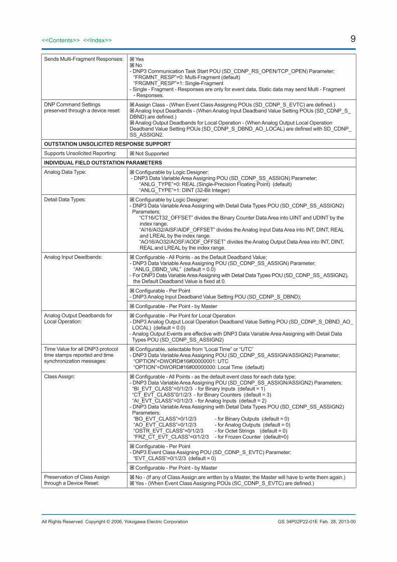
Sends Multi-Fragment Responses: Yes No - DNP3 Communication Task Start POU (SD_CDNP_RS_OPEN/TCP_OPEN) Parameter; “FRGMNT_RESP”=0: Multi-Fragment (default) “FRGMNT_RESP”=1: Single-Fragment- Single - Fragment - Responses are only for event data, Static data may send Multi - Fragment - Responses.
DNP Command Settings preserved through a device reset:
AssignClass-(WhenEventClassAssigningPOUs(SD_CDNP_S_EVTC)aredefined.) Analog Input Deadbands - (When Analog Input Deadband Value Setting POUs (SD_CDNP_S_DBND)aredefined.) Analog Output Deadbands for Local Operation - (When Analog Output Local Operation DeadbandValueSettingPOUs(SD_CDNP_S_DBND_AO_LOCAL)aredefinedwithSD_CDNP_SS_ASSIGN2.
OUTSTATION UNSOLICITED RESPONSE SUPPORTSupports Unsolicited Reporting: Not Supported
INDIVIDUAL FIELD OUTSTATION PARAMETERSAnalog Data Type: ConfigurablebyLogicDesigner;
- DNP3 Data Variable Area Assigning POU (SD_CDNP_SS_ASSIGN) Parameter; “ANLG_TYPE”=0: REAL (Single-Precision Floating Point) (default) “ANLG_TYPE”=1: DINT (32-Bit Integer)
Detail Data Types: ConfigurablebyLogicDesigner;- DNP3 Data Variable Area Assigning with Detail Data Types POU (SD_CDNP_SS_ASSIGN2) Parameters; “CT16/CT32_OFFSET” divides the Binary Counter Data Area into UINT and UDINT by the index range. “AI16/AI32/AISF/AIDF_OFFSET” divides the Analog Input Data Area into INT, DINT, REAL and LREAL by the index range. “AO16/AO32/AOSF/AODF_OFFSET” divides the Analog Output Data Area into INT, DINT, REAL and LREAL by the index range.
Analog Input Deadbands: Configurable-AllPoints-astheDefaultDeadbandValue;- DNP3 Data Variable Area Assigning POU (SD_CDNP_SS_ASSIGN) Parameter; “ANLG_DBND_VAL” (default = 0.0)- For DNP3 Data Variable Area Assigning with Detail Data Types POU (SD_CDNP_SS_ ASSIGN2), theDefaultDeadbandValueisfixedat0.
Configurable-PerPoint- DNP3 Analog Input Deadband Value Setting POU (SD_CDNP_S_DBND);
Configurable-PerPoint-byMaster
Analog Output Deadbands for Local Operation:
Configurable-PerPointforLocalOperation- DNP3 Analog Output Local Operation Deadband Value Setting POU (SD_CDNP_S_DBND_AO_ LOCAL) (default = 0.0)- Analog Output Events are effective with DNP3 Data Variable Area Assigning with Detail Data Types POU (SD_CDNP_SS_ASSIGN2)
Time Value for all DNP3 protocol time stamps reported and time synchronization messages:
Configurable,selectablefrom“LocalTime”or“UTC”- DNP3 Data Variable Area Assigning POU (SD_CDNP_SS_ASSIGN/ASSIGN2) Parameter; “OPTION”=DWORD#16#00000001: UTC “OPTION”=DWORD#16#00000000: Local Time (default)
Class Assign: Configurable-AllPoints-asthedefaulteventclassforeachdatatype;- DNP3 Data Variable Area Assigning POU (SD_CDNP_SS_ASSIGN/ASSIGN2) Parameters; “BI_EVT_CLASS”=0/1/2/3 - for Binary Inputs (default = 1) “CT_EVT_CLASS”0/1/2/3 - for Binary Counters (default = 3) “AI_EVT_CLASS”=0/1/2/3 - for Analog Inputs (default = 2)- DNP3 Data Variable Area Assigning with Detail Data Types POU (SD_CDNP_SS_ASSIGN2) Parameters; “BO_EVT_CLASS”=0/1/2/3 - for Binary Outputs (default = 0) “AO_EVT_CLASS”=0/1/2/3 - for Analog Outputs (default = 0) “OSTR_EVT_CLASS”=0/1/2/3 - for Octet Strings (default = 0) “FRZ_CT_EVT_CLASS”=0/1/2/3 - for Frozen Counter (default=0)
Configurable-PerPoint- DNP3 Event Class Assigning POU (SD_CDNP_S_EVTC) Parameter; “EVT_CLASS”=0/1/2/3 (default = 0)
Configurable-PerPoint-byMaster
Preservation of Class Assign through a Device Reset:
No - (If any of Class Assign are written by a Master, the Master will have to write them again.)Yes-(WhenEventClassAssigningPOUs(SC_CDNP_S_EVTC)aredefined.)
Feb. 28, 2013-00
10
All Rights Reserved. Copyright © 2006, Yokogawa Electric Corporation
<<Contents>> <<Index>>
GS 34P02P22-01E
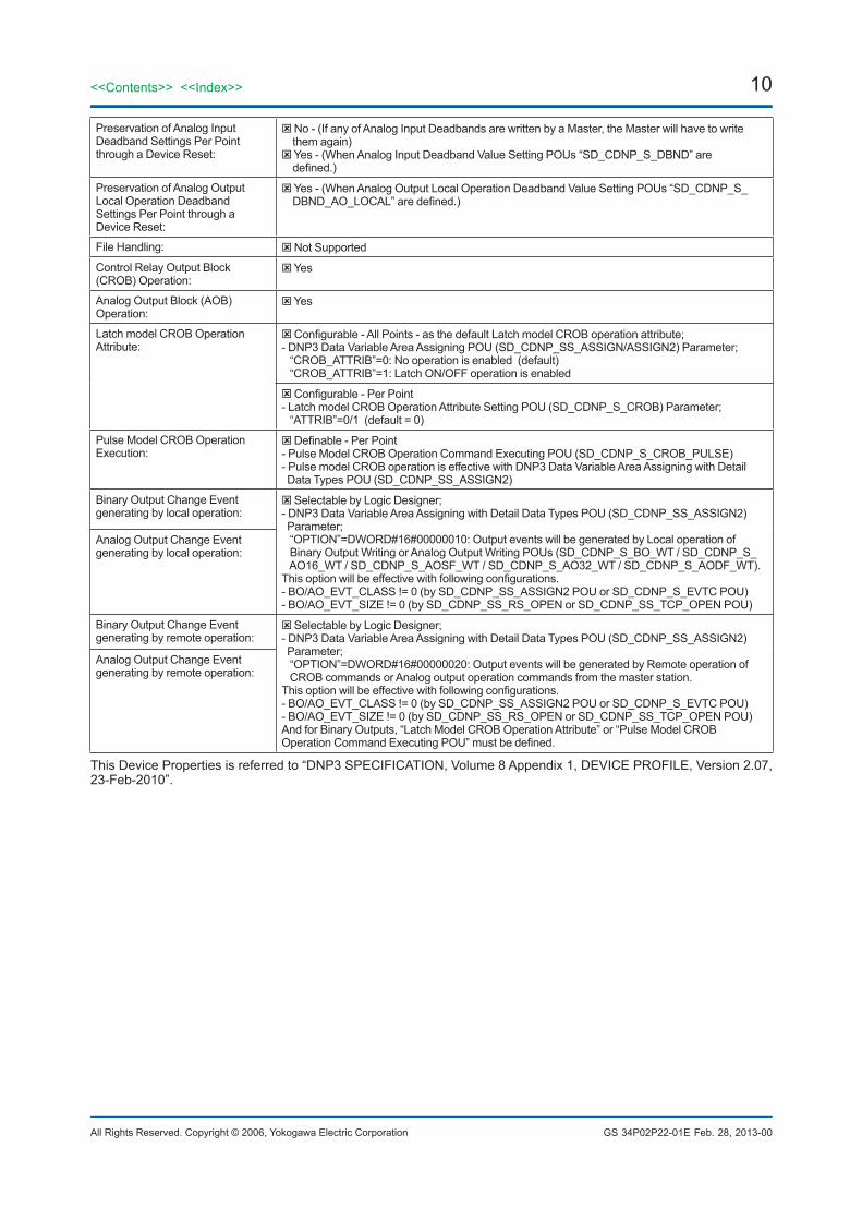
Preservation of Analog Input Deadband Settings Per Point through a Device Reset:
No - (If any of Analog Input Deadbands are written by a Master, the Master will have to write them again) Yes - (When Analog Input Deadband Value Setting POUs “SD_CDNP_S_DBND” are defined.)
Preservation of Analog Output Local Operation Deadband Settings Per Point through a Device Reset:
Yes - (When Analog Output Local Operation Deadband Value Setting POUs “SD_CDNP_S_DBND_AO_LOCAL”aredefined.)
File Handling: Not Supported
Control Relay Output Block (CROB) Operation:
Yes
Analog Output Block (AOB) Operation:
Yes
Latch model CROB Operation Attribute:
Configurable-AllPoints-asthedefaultLatchmodelCROBoperationattribute;- DNP3 Data Variable Area Assigning POU (SD_CDNP_SS_ASSIGN/ASSIGN2) Parameter; “CROB_ATTRIB”=0: No operation is enabled (default) “CROB_ATTRIB”=1: Latch ON/OFF operation is enabled
Configurable-PerPoint- Latch model CROB Operation Attribute Setting POU (SD_CDNP_S_CROB) Parameter; “ATTRIB”=0/1 (default = 0)
Pulse Model CROB Operation Execution:
Definable-PerPoint- Pulse Model CROB Operation Command Executing POU (SD_CDNP_S_CROB_PULSE)- Pulse model CROB operation is effective with DNP3 Data Variable Area Assigning with Detail Data Types POU (SD_CDNP_SS_ASSIGN2)
Binary Output Change Event generating by local operation:
Selectable by Logic Designer;- DNP3 Data Variable Area Assigning with Detail Data Types POU (SD_CDNP_SS_ASSIGN2) Parameter; “OPTION”=DWORD#16#00000010: Output events will be generated by Local operation of Binary Output Writing or Analog Output Writing POUs (SD_CDNP_S_BO_WT / SD_CDNP_S_ AO16_WT / SD_CDNP_S_AOSF_WT / SD_CDNP_S_AO32_WT / SD_CDNP_S_AODF_WT).Thisoptionwillbeeffectivewithfollowingconfigurations.- BO/AO_EVT_CLASS != 0 (by SD_CDNP_SS_ASSIGN2 POU or SD_CDNP_S_EVTC POU)- BO/AO_EVT_SIZE != 0 (by SD_CDNP_SS_RS_OPEN or SD_CDNP_SS_TCP_OPEN POU)
Analog Output Change Event generating by local operation:
Binary Output Change Event generating by remote operation:
Selectable by Logic Designer;- DNP3 Data Variable Area Assigning with Detail Data Types POU (SD_CDNP_SS_ASSIGN2) Parameter; “OPTION”=DWORD#16#00000020: Output events will be generated by Remote operation of CROB commands or Analog output operation commands from the master station.Thisoptionwillbeeffectivewithfollowingconfigurations.- BO/AO_EVT_CLASS != 0 (by SD_CDNP_SS_ASSIGN2 POU or SD_CDNP_S_EVTC POU)- BO/AO_EVT_SIZE != 0 (by SD_CDNP_SS_RS_OPEN or SD_CDNP_SS_TCP_OPEN POU)And for Binary Outputs, “Latch Model CROB Operation Attribute” or “Pulse Model CROB OperationCommandExecutingPOU”mustbedefined.
Analog Output Change Event generating by remote operation:
This Device Properties is referred to “DNP3 SPECIFICATION, Volume 8 Appendix 1, DEVICE PROFILE, Version 2.07, 23-Feb-2010”.
Feb. 28, 2013-00

11<<Contents>> <<Index>>
All Rights Reserved. Copyright © 2006, Yokogawa Electric Corporation GS 34P02P22-01E
●Capabilities for Device Database
SINGLE-BIT BINARY INPUT POINTSStatic (Steady-State) Object Number: 1Event Object Number: 2Static Variation reported when variation 0 requested
Variation2-Single-bitwithflag
Event Variation reported when variation 0 requested
Variation 2 - with absolute time
Event reporting mode All events
Binary Inputs included in Class 0 response:
Always
DefinitionofBinaryInputPointList: ConfigurablebyLogicDesigner;- DNP3 Binary Input Data Read/Write POU (SD_CDNP_S_BI_RD/WT)- Default Class can be assigned for All Points; - by DNP3 Data Variable Area Assigning POU (SD_CDNP_SS_ASSIGN/ASSIGN2) Parameter; “BI_EVT_CLASS” (default=1)- Event Class can be assigned Point by Point; - by Event Class Assigning POU (SD_CDNP_S_EVTC) or by Master-EventSizecanbeconfiguredforAllPoints; - by DNP3 Communication Task Starting POU (SD_CDNP_SS_RS_OPEN/TCP_OPEN) Parameter; “BI_EVT_SIZE” (default=500)
BINARY OUTPUT STATUS AND CONTROL RELAY OUTPUT BLOCKBinary Output Status Object Number: 10Binary Output Event Object Number: 11CROB Object Number: 12Minimum pulse time allowed with Trip, Close and Pulse On/Off commands.
Fixed at 0 ms (accuracy will be the control task execution period)- However, the 0-ms On-time for Trip/Close/Pulse On commands and the 0-ms Off-time for Trip/ Close/Pulse Off commands are not allowed.
Maximum pulse time allowed with Trip, Close and Pulse On/Off commands.
Fixed at 60000 ms (accuracy will be the control task execution period)
Binary Output Status included in Class 0 response:
Always
Static Variation reported when variation 0 requested:
Variation2-Single-bitwithflag
Event Variation reported when variation 0 requested:
Variation 2 - with absolute time
Event reporting mode: All events
Maximum Time between Select and Operate:
Configurable,rangefrom1to600seconds- By DNP3 Communication Task Starting POU (SD_CDNP_SS_RS_OPEN/TCP_OPEN) Parameter; “SBO_SEL_TOUT” (default=5)- SBO operation is effective with DNP3 Data Variable Area Assigning with Detail Data Types POU (SD_CDNP_SS_ASSIGN2)
DefinitionofBinaryOutputStatus/ Control Relay Output Block Point List:
ConfigurablebyLogicDesigner;- DNP3 Binary Output Data Read/Write POU (SD_CDNP_S_BO_RD/WT)- Latch model CROB operation can be enabled for All Points; - by DNP3 Data Variable Area Assigning POU (SD_CDNP_SS_ASSIGN/ASSIGN2) Parameter; “CROB_ATTRIB”- Latch model CROB operation can be enabled by Point by Point; - by model CROB operation Attribute Setting POU (SD_CDNP_S_CROB)-PulsemodelCROBoperationcommandexecutioncanbedefinedbyPointbyPoint; - by Pulse Model CROB Operation Command Executing POU (SD_CDNP_S_CROB_PULSE)- Pulse ON/OFF time will be guaranteed in the accuracy for the control task execution period.- Pulse model CROB operation is effective with DNP3 Data Variable Area Assigning with Detail Data Types POU (SD_CDNP_SS_ASSIGN2)- Default Class can be assigned for All Points, - by DNP3 Variable Area Assigning with Detail Data Types POU (SD_CDNP_SS_ASSIGN2) Parameter; “BO_EVT_CLASS” (default=0)- Event Class can be assigned Point by Point; - by Event Class Assigning POU (SD_CDNP_S_EVTC) or by Master-EventSizecanbeconfiguredforAllPoints; - by DNP3 Communication Task Starting POU (SD_CDNP_SS_RS_OPEN/TCP_OPEN) Parameter; “BO_EVT_SIZE” (default=0)
Feb. 28, 2013-00

12
All Rights Reserved. Copyright © 2006, Yokogawa Electric Corporation
<<Contents>> <<Index>>
GS 34P02P22-01E
COUNTERS/FROZEN COUNTERSStatic Counter Object Number: 20Static Frozen Counter Object Number: 21Counter Event Object Number: 22Frozen Counter Event Object Number: 23Static Counter Variation reported when variation 0 requested
Variation1 -32-bitwithflag(withASSIGNPOU) Variation 1 or 2 ; Based on point index (with ASSIGN2 POU)
Counter Event Variation reported when variation 0 requested
Variation5 -32-bitwithflagandtime(withASSIGNPOU) Variation 5 or 6 ; Based on point index (with ASSIGN2 POU)
Counter included in Class 0 response:
Always
Counter Event reporting mode All events
Static Frozen Counter Variation reported when variation 0 requested:
Variation 1 or 2 ; Based on point index (with ASSIGN2 POU)
Frozen Counter Event Variation reported when variation 0 requested:
Variation 1 or 2 ; Based on point index (with ASSIGN2 POU)
Frozen Counters included in Class 0 response:
Always(default) Never (can be selected by Logic Designer SD_CDNP_SS_ASSIGN2 POU OPTION “Frozen counter class 0 response stop bit”)
Frozen Counter Event reporting mode:
All events
Counter Roll Over at: 32 Bits (4,294,967,295) (with ASSIGN POU) 16 Bits (65,535) or 32 Bits (4,294,967,295) ; Based on point index (with ASSIGN2 POU)
Counter frozen by means of: Master Request
DefinitionofCounterPointList: ConfigurablebyLogicDesigner;- DNP3 32-Bit Binary Counter Data Read/Write POU (SD_CDNP_S_CT32_RD/WT)- Default Class can be assigned for All Points; - by DNP3 Variable Area Assigning POU (SD_CDNP_SS_ASSIGN/ASSIGN2) Parameter; “CT_EVT_CLASS” (default=3) - by DNP3 Variable Area Assigning with Detail Data Types (SD_CDNP_SS_ASSIGN2) Parameter; “FRZ_CT_EVT_CLASS” (default=0)- Event Class can be assigned Point by Point; - by Event Class Assigning POU (SD_CDNP_S_EVTC) or by Master-EventSizecanbeconfiguredforAllPoints; - by DNP3 Communication Task Starting POU (SD_CDNP_SS_RS_OPEN/TCP_OPEN) Parameter; “CT_EVT_SIZE” (default=500) and “FRZ_CT_EVT_SIZE” (default=0)
ANALOG INPUT POINTSStatic (Steady-State) Object Number: 30Event Object Number: 32Analog Input Deadband Object Number: 34Static Variation reported when variation 0 requested
Variation1-32-bitwithflagVariation5-single-precisionfloatingpointwithflag Variation 1, 2 or 5 ; Based on point index
(for DINT with ASSIGN POU)(for REAL with ASSIGN POU)(with ASSIGN2 POU)
Event Variation reported when variation 0 requested
Variation 3 - 32-bit with time Variation7-single-precisionfloatingpointwithtime Variation 2, 4 or 7 ; Based on point index
(for DINT with ASSIGN POU)(for REAL with ASSIGN POU)(with ASSIGN2 POU)
Analog Input Deadband reported when variation 0 requested
Variation 2 - 32-bit analog input deadbandVariation3-single-precisionfloatingpointdeadband Variation 1, 2 or 3 ; Based on point index
(for DINT with ASSIGN POU)(for REAL with ASSIGN POU)(with ASSIGN2 POU)
Change Event reporting mode All events
Analog Inputs included in Class 0 response:
Always
How Deadbands are set: ConfigurablethroughDNPConfigurablebyLogicDesigner- Refer to “Analog Input Deadband Default Value” and “Analog Input Deadbands” at section “INDIVIDUAL FIELD OUTSTATION PARAMETERS”.
Analog Input Deadband Algorithm: Simple - just compare the difference from the previous reported value
Feb. 28, 2013-00

13<<Contents>> <<Index>>
All Rights Reserved. Copyright © 2006, Yokogawa Electric Corporation GS 34P02P22-01E
DefinitionofAnalogInputPointList:
ConfigurablebyLogicDesigner;- 16-Bit Analog Input Data Read/Write POU (SD_CDNP_S_AI16_RD/WT) (with ASSIGN2)- 32-Bit Analog Input Data Read/Write POU (SD_CDNP_AI32_RD/WT) (with ASSIGN/ASSIGN2)- Single-Precision Floating Point Analog Input Data Read/Write POU (SD_CDNP_S_AISF_RD/ WT) (with ASSIGN/ASSIGN2)- Double-Precision Floating Point Analog Input Data Read/Write POU (SD_CDNP_S_AIDF_RD/ WT) (with ASSIGN2 POU)- Default Class can be assigned for All Points, - by DNP3 Variable Area Assigning POU (SD_CDNP_SS_ASSIGN/ASSIGN2) Parameter; “AI_EVT_CLASS”- Event Class can be assigned Point by Point; - by Event Class Assigning POU (SD_CDNP_S_EVTC) or by Master-EventSizecanbeconfiguredforAllPoints; - by DNP3 Communication Task Starting POU (SD_CDNP_SS_RS_OPEN/TCP_OPEN) Parameter; “AI_EVT_SIZE” (default=0)
ANALOG OUTPUT STATUS AND ANALOG OUTPUT CONTROL BLOCKAnalog Output Status Object Number: 40Analog Output Control Block Object Number: 41Analog Output Event Object Number: 42Static Analog Output Status Variation reported when variation 0 requested
Variation1-32-bitwithflagVariation3-single-precisionfloatingpointwithflag Variation 1, 2 or 3 ; Based on point index
(for DINT with ASSIGN POU)(for REAL with ASSIGN POU)(with ASSIGN2 POU)
Analog Output Status included in Class 0 response:
Always
Event Variation reported when variation 0 requested:
Variation 3 - 32-bit with timeVariation7-single-precisionfloatingpointwithtime Variation 3, 4 or 7 ; Based on point index
(for DINT with ASSIGN POU)(for REAL with ASSIGN POU)(with ASSIGN2 POU)
Event reporting mode: All events
Maximum Time between Select and Operate:
Configurable,rangefrom1to600seconds- By DNP3 Communication Task Starting POU (SD_CDNP_SS_RS_OPEN/TCP_OPEN) Parameter; “SBO_SEL_TOUT” (default=5)- SBO operation is effective with DNP3 Data Variable Area Assigning with Detail Data Types POU (SD_CDNP_SS_ ASSIGN2)
Analog Output Local Operation Deadband Algorithm:
Simple- Just compare the difference from the previous reported value- Analog Output Local Operation Deadband can be
DefinitionofAnalogOutput/Analog Output Block Point List:
ConfigurablebyLogicDesigner;- DNP3 16-Bit Analog Output Data Read/Write POU (SD_CDNP_AO32_RD/WT) (with ASSIGN2)- DNP3 32-Bit Analog Output Data Read/Write POU (SD_CDNP_AO32_RD/WT) (with ASSIGN/ ASSIGN2)- DNP3 Single-Precision Floating Point Analog Output Data Read/Write POU (SD_CDNP_S_ AOSF_RD/WT) (with ASSIGN/ASSIGN2)- DNP3 Double-Precision Floating Point Analog Output Data Read/Write POU (SD_CDNP_S_ AOSF_RD/WT) (with ASSIGN2)- Default Class can be assigned for All Points, - by DNP3 Variable Area Assigning with Detail Data Types POU (SD_CDNP_SS_ASSIGN2) Parameter; “AO_EVT_CLASS”- Event Class can be assigned Point by Point; - by Event Class Assigning POU (SD_CDNP_S_EVTC) or by Master-EventSizecanbeconfiguredforAllPoints; - by DNP3 Communication Task Starting POU (SD_CDNP_SS_RS_OPEN/TCP_OPEN) Parameter; “AO_EVT_SIZE” (default=0)
Feb. 28, 2013-00

14
All Rights Reserved. Copyright © 2006, Yokogawa Electric Corporation
<<Contents>> <<Index>>
GS 34P02P22-01E
OCTET STRING POINTSStatic (Steady-State) Object Number: 110110Event Object Number: 111Event reporting mode: All events
Octet Strings included in Class 0 response:
Always(default) Never (can be selected by Logic Designer SD_CDNP_SS_ASSIGN2 POU OPTION “Octet string class 0 response stop bit”)
Maximum number of octets that can be handled in an Octet String Data:
Fixed at 32-Octets- Octet String Points can be used with ASSIGN2 POU
Definitionof32-OctetStringPointList:
ConfigurablebyLogicDesigner;- DNP3 32-Octet String Data Read/Write POU (SD_CDNP_S_OSTR32_RD/WT)- Default Class can be assigned for All Points; - by DNP3 Variable Area Assigning with Detail Data Types POU (SD_CDNP_SS_ASSIGN2) Parameter; “OSTR_EVT_CLASS”- Event Class can be assigned Point by Point; - by Event Class Assigning POU (SD_CDNP_S_EVTC)-EventSizecanbeconfiguredforAllPoints; - by DNP3 Communication Task Starting POU (SD_CDNP_SS_RS_OPEN/TCP_OPEN) Parameter; “OSTR_EVT_SIZE” (default=0)
This Capabilities for Device Database is referred to “DNP3 SPECIFICATION, Volume 8 Appendix 1, DEVICE PROFILE,Version2.07,23-Feb-2010”and“DNP3DeviceProfiletransformationfileVersion2-07”.
Feb. 28, 2013-00

15<<Contents>> <<Index>>
All Rights Reserved. Copyright © 2006, Yokogawa Electric Corporation GS 34P02P22-01E
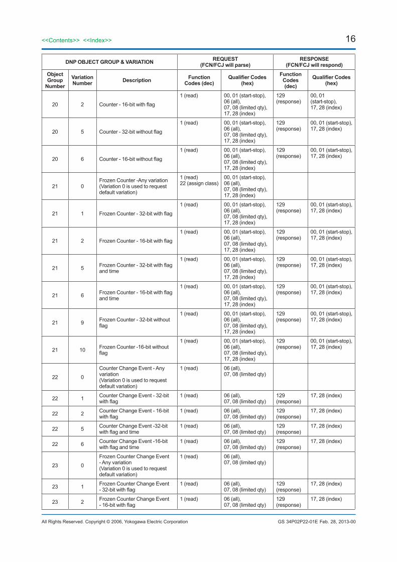
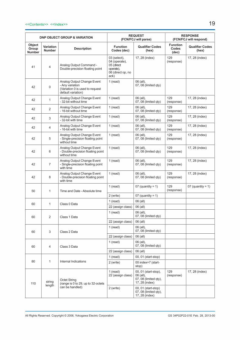
●Implementation Table
DNP OBJECT GROUP & VARIATION REQUEST(FCN/FCJ will parse)
RESPONSE(FCN/FCJ will respond)
ObjectGroup
NumberVariationNumber Description Function
Codes (dec)Qualifier Codes
(hex)Function
Codes(dec)
Qualifier Codes(hex)
1 0
Binary Input - Any variation(Variation 0 is used to request default variation)
1 (read),22 (assign class)
00, 01 (start-stop),06 (all),07, 08 (limited qty),17, 28 (index)
1 1 Binary Input - Packed format
1 (read) 00, 01 (start-stop),06 (all),07, 08 (limited qty),17, 28 (index)
129 (response)
00, 01 (start-stop),17, 28 (index)
1 2 BinaryInput-Withflags
1 (read) 00, 01 (start-stop),06 (all),07, 08 (limited qty),17, 28 (index)
129 (response)
00, 01 (start-stop),17, 28 (index)
2 0
Binary Input Change Event - Any variation(Variation 0 is used to request default variation)
1 (read) 06 (all),07, 08 (limited qty)
2 1 Binary Input Change Event without Time
1 (read) 06 (all),07, 08 (limited qty)
129 (response)
17, 28 (index)
2 2 Binary Input Change Event - With absolute time
1 (read) 06 (all),07, 08 (limited qty)
129 (response)
17, 28 (index)
10 0
Binary Output Status - Any variation(Variation 0 is used to request default variation)
1 (read)22 (assign class)
00, 01 (start-stop),06 (all),07, 08 (limited qty),17, 28 (index)
10 1 Binary Output Status - Packed format
1 (read) 00, 01 (start-stop),06 (all),07, 08 (limited qty),17, 28 (index)
129 (response)
00, 01 (start-stop),17, 28 (index)
10 2 Binary Output Status - Output statuswithflags
1 (read) 00, 01 (start-stop),06 (all),07, 08 (limited qty),17, 28 (index)
129 (response)
00, 01 (start-stop),17, 28 (index)
11 0
Binary Output Event - Any variation(Variation 0 is used to request default variation)
1 (read) 00, 01 (start-stop),06 (all)
11 1 Binary Output Event - Status without time
1 (read) 00, 01 (start-stop),06 (all)
129 (response)
17, 28 (index)
11 2 Binary Output Event - Status with time
1 (read) 00, 01 (start-stop),06 (all)
129 (response)
17, 28 (index)
12 1Binary Output Command - Control relay outputblock (CROB)
03 (select),04 (operate),05 (direct perate),06 (direct op, no ack)
17, 28 (index) 129 (response)
17, 28 (index)
20 0Counter – Any variation(Variation 0 is used to request default variation)
1 (read),7 (freeze),8 (freeze no ack),9 (freeze & clear),10 (frz & clr, no ack),22 (assign class)
00, 01 (start-stop),06 (all),07, 08 (limited qty),17, 28 (index)
20 1 Counter-32-bitwithflag
1 (read) 00, 01 (start-stop),06 (all),07, 08 (limited qty),17, 28 (index)
129 (response)
00, 01 (start-stop),17, 28 (index)
Feb. 28, 2013-00
16
All Rights Reserved. Copyright © 2006, Yokogawa Electric Corporation
<<Contents>> <<Index>>
GS 34P02P22-01E
DNP OBJECT GROUP & VARIATION REQUEST(FCN/FCJ will parse)
RESPONSE(FCN/FCJ will respond)
ObjectGroup
NumberVariationNumber Description Function
Codes (dec)Qualifier Codes
(hex)Function
Codes(dec)
Qualifier Codes(hex)
20 2 Counter-16-bitwithflag
1 (read) 00, 01 (start-stop),06 (all),07, 08 (limited qty),17, 28 (index)
129 (response)
00, 01 (start-stop),17, 28 (index)
20 5 Counter-32-bitwithoutflag
1 (read) 00, 01 (start-stop),06 (all),07, 08 (limited qty),17, 28 (index)
129 (response)
00, 01 (start-stop),17, 28 (index)
20 6 Counter-16-bitwithoutflag
1 (read) 00, 01 (start-stop),06 (all),07, 08 (limited qty),17, 28 (index)
129 (response)
00, 01 (start-stop),17, 28 (index)
21 0Frozen Counter -Any variation(Variation 0 is used to request default variation)
1 (read)22 (assign class)
00, 01 (start-stop),06 (all),07, 08 (limited qty),17, 28 (index)
21 1 FrozenCounter-32-bitwithflag
1 (read) 00, 01 (start-stop),06 (all),07, 08 (limited qty),17, 28 (index)
129 (response)
00, 01 (start-stop),17, 28 (index)
21 2 FrozenCounter-16-bitwithflag
1 (read) 00, 01 (start-stop),06 (all),07, 08 (limited qty),17, 28 (index)
129 (response)
00, 01 (start-stop),17, 28 (index)
21 5 FrozenCounter-32-bitwithflagand time
1 (read) 00, 01 (start-stop),06 (all),07, 08 (limited qty),17, 28 (index)
129 (response)
00, 01 (start-stop),17, 28 (index)
21 6 FrozenCounter-16-bitwithflagand time
1 (read) 00, 01 (start-stop),06 (all),07, 08 (limited qty),17, 28 (index)
129 (response)
00, 01 (start-stop),17, 28 (index)
21 9 Frozen Counter - 32-bit without flag
1 (read) 00, 01 (start-stop),06 (all),07, 08 (limited qty),17, 28 (index)
129 (response)
00, 01 (start-stop),17, 28 (index)
21 10 Frozen Counter -16-bit without flag
1 (read) 00, 01 (start-stop),06 (all),07, 08 (limited qty),17, 28 (index)
129 (response)
00, 01 (start-stop),17, 28 (index)
22 0
Counter Change Event - Any variation(Variation 0 is used to request default variation)
1 (read) 06 (all),07, 08 (limited qty)
22 1 Counter Change Event - 32-bit withflag
1 (read) 06 (all),07, 08 (limited qty)
129 (response)
17, 28 (index)
22 2 Counter Change Event - 16-bit withflag
1 (read) 06 (all),07, 08 (limited qty)
129 (response)
17, 28 (index)
22 5 Counter Change Event -32-bit withflagandtime
1 (read) 06 (all),07, 08 (limited qty)
129 (response)
17, 28 (index)
22 6 Counter Change Event -16-bit withflagandtime
1 (read) 06 (all),07, 08 (limited qty)
129 (response)
17, 28 (index)
23 0
Frozen Counter Change Event - Any variation(Variation 0 is used to request default variation)
1 (read) 06 (all),07, 08 (limited qty)
23 1 Frozen Counter Change Event -32-bitwithflag
1 (read) 06 (all),07, 08 (limited qty)
129 (response)
17, 28 (index)
23 2 Frozen Counter Change Event -16-bitwithflag
1 (read) 06 (all),07, 08 (limited qty)
129 (response)
17, 28 (index)
Feb. 28, 2013-00

17<<Contents>> <<Index>>
All Rights Reserved. Copyright © 2006, Yokogawa Electric Corporation GS 34P02P22-01E
DNP OBJECT GROUP & VARIATION REQUEST(FCN/FCJ will parse)
RESPONSE(FCN/FCJ will respond)
ObjectGroup
NumberVariationNumber Description Function
Codes (dec)Qualifier Codes
(hex)Function
Codes(dec)
Qualifier Codes(hex)
23 5 Frozen Counter Change Event -32-bitwithflagandtime
1 (read) 06 (all),07, 08 (limited qty)
129 (response)
17, 28 (index)
23 6 Frozen Counter Change Event -16-bitwithflagandtime
1 (read) 06 (all),07, 08 (limited qty)
129 (response)
17, 28 (index)
30 0Analog Input - Any variation(Variation 0 is used to request default variation)
1 (read),22 (assign class)
00, 01 (start-stop),06 (all),07, 08 (limited qty),17, 28 (index)
30 1 AnalogInput-32-bitwithflag
1 (read) 00, 01 (start-stop),06 (all),07, 08 (limited qty),17, 28 (index)
129 (response)
00, 01 (start-stop),17, 28 (index)
30 2 AnalogInput-16-bitwithflag
1 (read) 00, 01 (start-stop),06 (all),07, 08 (limited qty),17, 28 (index)
129 (response)
00, 01 (start-stop),17, 28 (index)
30 3 AnalogInput-32-bitwithoutflag
1 (read) 00, 01 (start-stop),06 (all),07, 08 (limited qty),17, 28 (index)
129 (response)
00, 01 (start-stop),17, 28 (index)
30 4 AnalogInput-16-bitwithoutflag
1 (read) 00, 01 (start-stop),06 (all),07, 08 (limited qty),17, 28 (index)
129 (response)
00, 01 (start-stop),17, 28 (index)
30 5 Analog Input - Single-precisionfloatingpointwithflag
1 (read) 00, 01 (start-stop),06 (all),07, 08 (limited qty),17, 28 (index)
129 (response)
00, 01 (start-stop),17, 28 (index)
30 6 Analog Input - Double-precisionfloatingpointwithflag
1 (read) 00, 01 (start-stop),06 (all),07, 08 (limited qty),17, 28 (index)
129 (response)
00, 01 (start-stop),17, 28 (index)
32 0
Analog Input Change Event - Any variation(Variation 0 is used to request default variation)
1 (read) 06 (all),07, 08 (limited qty)
32 1 Analog Input Change Event - 32-bit without time
1 (read) 06 (all),07, 08 (limited qty)
129 (response)
17, 28 (index)
32 2 Analog Input Change Event -16-bit without time
1 (read) 06 (all),07, 08 (limited qty)
129 (response)
17, 28 (index)
32 3 Analog Input Change Event - 32-bit with time
1 (read) 06 (all),07, 08 (limited qty)
129 (response)
17, 28 (index)
32 4 Analog Input Change Event - 16-bit with time
1 (read) 06 (all),07, 08 (limited qty)
129 (response)
17, 28 (index)
32 5Analog Input Change Event -Single-precisionfloatingpointwithout time
1 (read) 06 (all),07, 08 (limited qty)
129 (response)
17, 28 (index)
32 6Analog Input Change Event -Double-precisionfloatingpointwithout time
1 (read) 06 (all),07, 08 (limited qty)
129 (response)
17, 28 (index)
32 7Analog Input Change Event -Single-precisionfloatingpointwith time
1 (read) 06 (all),07, 08 (limited qty)
129 (response)
17, 28 (index)
32 8Analog Input Change Event -Double-precisionfloatingpointwith time
1 (read) 06 (all),07, 08 (limited qty)
129 (response)
17, 28 (index)
34 0
Analog Input Deadband - Any variation(Variation 0 is used to request default variation)
1 (read) 00, 01 (start-stop),06 (all),07, 08 (limited qty),17, 28 (index)
Feb. 28, 2013-00

18
All Rights Reserved. Copyright © 2006, Yokogawa Electric Corporation
<<Contents>> <<Index>>
GS 34P02P22-01E
DNP OBJECT GROUP & VARIATION REQUEST(FCN/FCJ will parse)
RESPONSE(FCN/FCJ will respond)
ObjectGroup
NumberVariationNumber Description Function
Codes (dec)Qualifier Codes
(hex)Function
Codes(dec)
Qualifier Codes(hex)
34 1 Analog Input Deadband - 16-bit
1 (read) 00, 01 (start-stop),06 (all),07, 08 (limited qty),17, 28 (index)
129 (response)
00, 01 (start-stop),17, 28 (index)
2 (write) 00, 01 (start-stop),07, 08 (limited qty),17, 28 (index)
34 2 Analog Input Deadband - 32-bit
1 (read) 00, 01 (start-stop),06 (all),07, 08 (limited qty),17, 28 (index)
129 (response)
00, 01 (start-stop),17, 28 (index)
2 (write) 00, 01 (start-stop),07, 08 (limited qty),17, 28 (index)
34 3 Analog Input Deadband - Single-precisionfloatingpoint
1 (read) 00, 01 (start-stop),06 (all),07, 08 (limited qty),17, 28 (index)
129 (response)
00, 01 (start-stop)17, 28 (index)
2 (write) 00, 01 (start-stop),07, 08 (limited qty),17, 28 (index)
40 0
Analog Output Status – Any variation(Variation 0 is used to request default variation)
1 (read)22 (assign class)
00, 01 (start-stop),06 (all),07, 08 (limited qty),17, 28 (index)
40 1 Analog Output Status -32-bit withflag
1 (read) 00, 01 (start-stop),06 (all),07, 08 (limited qty),17, 28 (index)
129 (response)
00, 01 (start-stop),17, 28 (index)
40 2 Analog Output Status - 16-bit withflag
1 (read) 00, 01 (start-stop),06 (all),07, 08 (limited qty),17, 28 (index)
129 (response)
00, 01 (start-stop),17, 28 (index)
40 3 Analog Output Status - Single-precisionfloatingpointwithflag
1 (read) 00, 01 (start-stop),06 (all),07, 08 (limited qty),17, 28 (index)
129 (response)
00, 01 (start-stop),17, 28 (index)
40 4 Analog Output Status - Double-precisionfloatingpointwithflag
1 (read) 00, 01 (start-stop),06 (all),07, 08 (limited qty),17, 28 (index)
129 (response)
00, 01 (start-stop),17, 28 (index)
41 1 Analog Output Command - 32-bit
03 (select),04 (operate),05 (direct operate),06 (direct op, no ack)
17, 28 (index) 129 (response)
17, 28 (index)
41 2 Analog Output Command - 16-bit
03 (select),04 (operate),05 (direct operate),06 (direct op, no ack)
17, 28 (index) 129 (response)
17, 28 (index)
41 3 Analog Output Command - Single-precisionfloatingpoint
03 (select),04 (operate),05 (direct operate),06 (direct op, no ack)
17, 28 (index) 129 (response)
17, 28 (index)
Feb. 28, 2013-00
19<<Contents>> <<Index>>
All Rights Reserved. Copyright © 2006, Yokogawa Electric Corporation GS 34P02P22-01E
DNP OBJECT GROUP & VARIATION REQUEST(FCN/FCJ will parse)
RESPONSE(FCN/FCJ will respond)
ObjectGroup
NumberVariationNumber Description Function
Codes (dec)Qualifier Codes
(hex)Function
Codes(dec)
Qualifier Codes(hex)
41 4 Analog Output Command - Double-precisionfloatingpoint
03 (select),04 (operate),05 (direct operate),06 (direct op, no ack)
17, 28 (index) 129 (response)
17, 28 (index)
42 0
Analog Output Change Event - Any variation(Variation 0 is used to request default variation)
1 (read) 06 (all),07, 08 (limited qty)
42 1 Analog Output Change Event - 32-bit without time
1 (read) 06 (all),07, 08 (limited qty)
129 (response)
17, 28 (index)
42 2 Analog Output Change Event - 16-bit without time
1 (read) 06 (all),07, 08 (limited qty)
129 (response)
17, 28 (index)
42 3 Analog Output Change Event - 32-bit with time
1 (read) 06 (all),07, 08 (limited qty)
129 (response)
17, 28 (index)
42 4 Analog Output Change Event - 16-bit with time
1 (read) 06 (all),07, 08 (limited qty)
129 (response)
17, 28 (index)
42 5Analog Output Change Event -Single-precisionfloatingpointwithout time
1 (read) 06 (all),07, 08 (limited qty)
129 (response)
17, 28 (index)
42 6Analog Output Change Event -Double-precisionfloatingpointwithout time
1 (read) 06 (all),07, 08 (limited qty)
129 (response)
17, 28 (index)
42 7Analog Output Change Event -Single-precisionfloatingpointwith time
1 (read) 06 (all),07, 08 (limited qty)
129 (response)
17, 28 (index)
42 8Analog Output Change Event -Double-precisionfloatingpointwith time
1 (read) 06 (all),07, 08 (limited qty)
129 (response)
17, 28 (index)
50 1 Time and Date - Absolute time1 (read) 07 (quantity = 1) 129
(response)07 (quantity = 1)
2 (write) 07 (quantity = 1)
60 1 Class 0 Data1 (read) 06 (all)
22 (assign class) 06 (all)
60 2 Class 1 Data1 (read) 06 (all),
07, 08 (limited qty)
22 (assign class) 06 (all)
60 3 Class 2 Data1 (read) 06 (all),
07, 08 (limited qty)
22 (assign class) 06 (all)
60 4 Class 3 Data1 (read) 06 (all),
07, 08 (limited qty)
22 (assign class) 06 (all)
80 1 Internal Indications1 (read) 00, 01 (start-stop)
2 (write) 00 index=7 (start-stop)
110 stringlength
Octet String(range is 0 to 29, up to 32-octets can be handled)
1 (read)22 (assign class)
00, 01 (start-stop),06 (all),07, 08 (limited qty),17, 28 (index)
129 (response)
17, 28 (index)
2 (write) 00, 01 (start-stop)07, 08 (limited qty),17, 28 (index)
Feb. 28, 2013-00
20
All Rights Reserved. Copyright © 2006, Yokogawa Electric Corporation
<<Contents>> <<Index>>
GS 34P02P22-01ESubject to change without notice.
DNP OBJECT GROUP & VARIATION REQUEST(FCN/FCJ will parse)
RESPONSE(FCN/FCJ will respond)
ObjectGroup
NumberVariationNumber Description Function
Codes (dec)Qualifier Codes
(hex)Function
Codes(dec)
Qualifier Codes(hex)
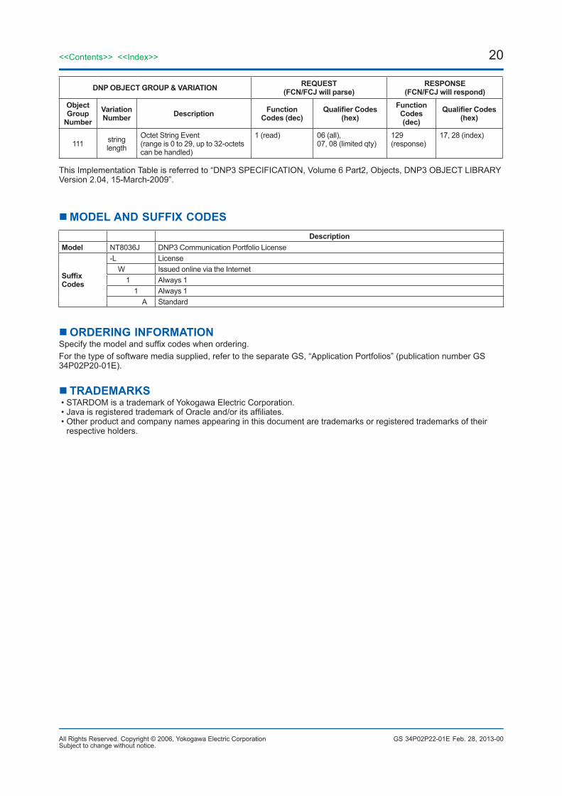
111 stringlength
Octet String Event(range is 0 to 29, up to 32-octets can be handled)
1 (read) 06 (all),07, 08 (limited qty)
129 (response)
17, 28 (index)
This Implementation Table is referred to “DNP3 SPECIFICATION, Volume 6 Part2, Objects, DNP3 OBJECT LIBRARY Version 2.04, 15-March-2009”.
MODEL AND SUFFIX CODESDescription
Model NT8036J DNP3 Communication Portfolio License
Suffix Codes
-L License W Issued online via the Internet 1 Always 1 1 Always 1 A Standard
ORDERING INFORMATIONSpecifythemodelandsuffixcodeswhenordering.For the type of software media supplied, refer to the separate GS, “Application Portfolios” (publication number GS 34P02P20-01E).
TRADEMARKS•STARDOMisatrademarkofYokogawaElectricCorporation.•JavaisregisteredtrademarkofOracleand/oritsaffiliates.•Otherproductandcompanynamesappearinginthisdocumentaretrademarksorregisteredtrademarksoftheir
respective holders.
Feb. 28, 2013-00