gen v lt1/lt4 installation guide -...
TRANSCRIPT

Gen V LT1/LT4 installation guide by Dave White – automobileman.com - rev c. - 02/03/2017
This is a brief and concise guide to those who are interested in installing the new generation of LT crate
engines offered by GM Performance.
Engine mounting plates
The LT block shares little with the previous generation of LS engines and requires a unique set of engine
mounting plates. I used a pair of sliding engine mounts from Dirty Dingo called LT adjustable conversion
mounts. They list for $154.95
They also make a single mounting bracket with four adjustable holes that runs $69.95.
ICT Billet also makes an LT engine swap bracket that retails for $64.95

Both systems use conventional small black Chevy Gen 1 engine mounting pads that will adapt to existing
engine mounting locations in classic cars such as Chevelles, Novas and Camaros. The stock engine cradle may
be a problem with a stock pan.
Art Morrison has just released their LT motor mounting plates – Poly is $285 and rubber is $240.
Engine Pan
Since both engines are available in dry sump or wet sump you must anticipate and design where your oil
reservoir will be if you’re going with the dry sump version. I went with the wet sump version and had to
modify my sump by cutting 1” off the front of the sump, but Moroso just came out with a new pan that should
solve most of the subframe issues.
Moroso part # 20155

Holley just released their new LT1/4 pan under part number 301-20.
GM’s new Gen V LT direct
injected engines are starting to
find their way into a large variety
of vehicles. They make great
power, plus they’re very durable
and reliable. Unfortunately, the
factory oil pans don’t always fit
or they hang too low for today’s
hot rods. Holley’s new LT Retro-
fit Engine Oil Pan is designed to
help! It provides maximum
clearance to the chassis and
ground, plus provides an OEM
fitment for durability and proper
sealing. These oil pans are
perfect for: 1967-‘02
Camaro/Firebird, 1968-‘74
Nova/Apollo/Ventura/Omega, 1978-‘87 G-body, 1964-‘72 A-body, and 1973-‘87 Chevy/GMC Full Size Trucks
Features: Designed for LT Engine Retro-Fit Installations in Classic Car and Truck Chassis Requiring More Oil Pan to Chassis
Clearance Around the Front Half of the Oil Pan Allows for up to 4.00” Crankshaft Stroke Can Be Used Anywhere a GM F-Body Oil Pan Can Be Used Provides OEM fitment - Oil filter mounting, OEM Engine NVH Suppression, OEM Flange Sealing, Proper Structural
Rigidity and OEM Bell-Housing Attachments. Traditional High-Quality Cast Aluminum Appearance With Clean Exterior Styling Provides Maximum Clearance for Vehicles Where the Steering Linkage is Behind the Engine cross-member Traditional high-quality cast aluminum appearance with clean exterior styling. Provides maximum clearance for vehicles where the steering linkage is behind the engine crossmember. Cast and machined aluminum Oil Cooler Port Provision 1/2” NPT port – Ideal for Turbo Oil Return or PCV Oil Return Hinge Door Baffles Available Complete Kit Includes: Windage Tray, Sump Baffle, OE Style Pick-Up Tube, Sump Port Plug, Oil Filter Stud, Billet Oil
Passage Cover, etc
The LT1 has a different oil cooler than the LT4 and it may or may not be an issue with mounting. The LT4 oil cooler is larger and hit the tubing that triangulated the Morrison front clip that I was using. I removed the sump and designed an air-cooled oil cooler

rather than using the existing water cooled radiator design. I removed the sump and designed an air-cooled oil cooler rather than using the existing water cooled radiator design. There have been numerous posts over the last year (2016) that identifies a cooling issue with LT4 engines that are used on the track and pushed hard. Once the oil temperature reaches 280 degrees the engine will shut down and run in “limp mode.” The 2017 Z06 and the ZL1 Camaro have improved cooling designs that will help with this problem. I remotely mounted a stacked plate cooler to the side and in front of the radiator on my ’68 Camaro.
Hydraulic Power Steering
This is a big problem since all the automobiles that are produced now use electric
power steering, both engines have no provision for hydraulic power steering. I saw
the 1970 GM SEMA Camaro and thought I could copy and use the system the factory
used to plumb in a GM type II power steering pump into the serpentine belt system.
This was not easy, took a considerable amount of time, but if you know how to
engineer and fabricate it’s not that bad.
The hydraulic power steering pulley simply replaces the idler pulley that was there. It’s a standard GM type II
pump that was sourced from Detroit Speed. I used a 2007 Dodge RAM power steering pulley that is slightly
undersized from stock. The factory actually took a stock 6 rib pulley, split it apart and welded two halves
together and then remachined it because GM does not manufacture an 8 rib pulley that will fit on the Type II
pump. I recently purchased an 8 rib pulley from Eddie Motorsports but the diameter is only 5” and it’s too
small (shown below).
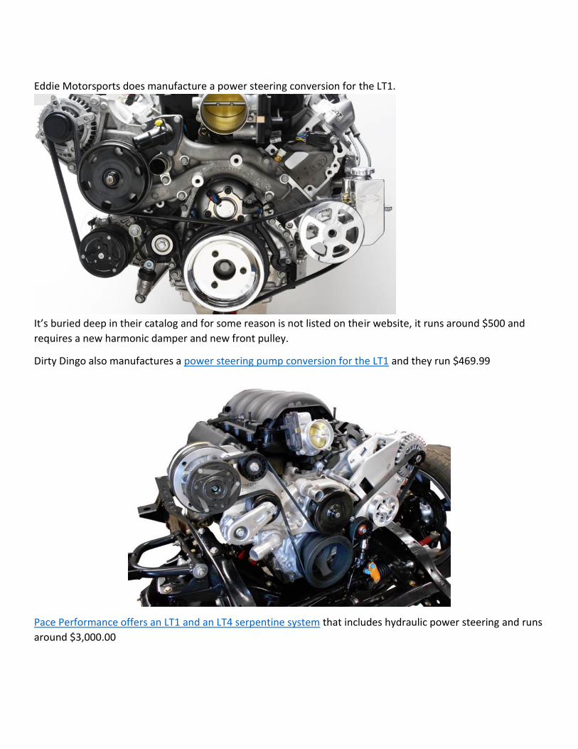
Eddie Motorsports does manufacture a power steering conversion for the LT1.
It’s buried deep in their catalog and for some reason is not listed on their website, it runs around $500 and
requires a new harmonic damper and new front pulley.
Dirty Dingo also manufactures a power steering pump conversion for the LT1 and they run $469.99
Pace Performance offers an LT1 and an LT4 serpentine system that includes hydraulic power steering and runs
around $3,000.00

Wiring and controller system
If you haven’t rewired a classic car for an LS or the LT series of engines, things have changed considerably since
the 50’s and 60’s. The controller system that comes with these engines includes a complete fuse panel and
ECM that controls every function of the engine. In the LS series of engines the ECM is relatively easy to mount
because it’s not that large, but in the LT engines it’s large, about the size of an iPad.
My biggest issue was trying to find a place for it because it simply
didn’t fit anywhere. GM buries these ECMs deep within the modern
cars and it’s a challenge just to find where they put them. I chose to
mount it as shown and modified my heater box, but I wouldn’t
recommend it. Instead I should have installed a Vintage Air System
and completely removed the existing heater system because then
you end up with a simple cover plate that goes over where the old
heater box used to be. It’s much cleaner and a simpler way to go,
plus it then gives you plenty of room to install this massive ECM.
The fuse box is just like the LS3 and includes all the fuses and relays
to run the engine and additional electrical demand, plus it controls
the fuel pump and the dual fan relays. You only need to hook up one
wire (ignition -pink) to your existing system to get things going. As for the body wiring harness, I suggest you
dispense with whatever is there and use American Autowire. They are simply the best in terms of schematics
and offer anything from the Route 9 to the Power Plus 20.

If you’ve got more than a simple street rod with power windows, 1500 watt amp or power seats, you’ll need
something more than the Route 9. They also offer complete restoration harnesses for cars like 1956 Chevys,
but they won’t work using the LT engines because the wiring theory is completely different than what was
done 50 years ago. Do not try to adapt one of these original harnesses to the LT engine. We don’t use
generators or ammeters anymore and we produce substantially more wattage than the older systems can
handle. I’ve done it both ways and in the end, it’s much better to remove what’s there and start from scratch.
VSS – Vehicle Speed Sensor
The VSS signal is required for these engines and cannot be omitted! If the engine does not see the VSS signal
it will go into “limp mode” and not allow anything more than 1/3 throttle. To wire in a digital tachometer use
this schematic.

Radiator
Since the LT4 develops 650 HP you need to make sure whatever radiator you’re using is up to handling the job,
and that means dual fans. There are lots of high-end radiators such as Ron Davis and AutoRad, but I ended up
using a US built radiator from Entrophy. This picture shows the LS/LT option with both inlet and outlet on the
same side. For those of you who have been running Gen 1/2 engines, these modern engines run much hotter,
the first fan kicks in at 207d and the second at 221d, do not attempt to modify these parameters. I’ve talked
with many old hot-rodders who do not understand this and attempt to lower the temperatures because they
feel uncomfortable with an engine running at those temperatures, this is foolish and will cause problems, not
to mention lower the overall performance of the engine.
Gauges and Instrumentation
These modern engines use something known as a CAN Bus (Controller Automotive Network) and GM’s
version is known as GMLINK. To get your gauges to work I suggest you read Autometer’s installation guides
for LS engines, first before you do anything. The easiest approach is to use Dakota Digital’s VHX gauge
system with the BIM-01-2 OBD 2 interface. What this does is read the information from the OBD 2 diagnostic
port and convert the signals into something that the VHX can understand.

The BIM-01-2 OBD-II (J1850/CAN) Interface allows you to plug directly into the engine diagnostic port,
extracting engine and transmission data from the vehicle's computer (ECM). The BIM-01-2 will collect and
output the following information to Dakota Digital Instrument Systems *:
Always available:
Speed
Tachometer
Engine Temp
Check Engine Indicator
Vehicle specific:
Intake Air Temp
Transmission Temp
Ambient Air Temp
Gear Position
Oil Pressure
“Due to the various factory and modified ECM's,
additional data including (Intake Temp, Transmission Temp, Ambient Air Temp, Oil Pressure, and Gear
Position) may be available, but will vary from application to application. Dakota Digital cannot guarantee
the presence or accuracy of the Intake Temp, Transmission Temp, Ambient Air Temp, Oil Pressure, or Gear
Position displays since this is a function of the ECM and matching OEM functional sensors.”
For LS and LT engines which have a 2 wire oil pressure GMLAN reference sensor the VHX system cannot
read this signal through the ODB connection. As shown above the LT4 already has an extra oil pressure
sensor located right above the oil filter. You can install Dakota Digital’s 03-8 sender which is included in
their gauge package with a 12mm x 1.5 adapter to read the oil pressure. To read the signal only requires
changing the signal from BUS to Sender in the setup procedure.
Also, there are no blank plugs that are available to install a water temperature sender. Your options are
limited here unless you want to install it in the water pump outlet (drill a hole), the radiator hose or the
radiator itself.

I completely redesigned the oil cooling system,
removed the oil cooler from the side of the pan
and installed conventional oil coolers at the
front of the radiator. I installed a conventional
sender (DD 04-5) at the end of the water pump.
This was my
solution, but it
may not be
something you
want to attempt.
The existing water temperature sensor is
shown on the top of the water pump, but you
cannot share this connection because it’s part of the CAN bus and won’t give you a signal that you can use unless
you install the Dakota Digital VHX with BIM-01-2.
Fuel Pump
GM recommends a Pulse Width Modulated returnless system.
The only vendor that I could find that would accept and use a conventional GM fuel pump 19303293 was
Rick’s Tanks in Texas. They manufacture both an adaptor plate and complete tanks.
They also offer specific fittings and the wiring adapter plugs for the fuel pump.

GM has decided that they no longer want to recycle unused gas from conventional pumps, so they’ve come up
with this new system to satisfy the demands of the new generation of Direct Injection Engines. Since the fuel
pressures can be upwards of 2,500 psi, the FPPM (Fuel Pump Pressure Module) monitors the fuel pressure
sensor (inline on the fuel hose) and communicates back and forth between the ECM and the fuel pump to
deliver sufficient pressure. It’s also recommended that you “do not use a fuel line filter” anywhere along the
system because the fuel pump itself has filters to take care of any issues. On a final note, there is no
conventional fuel pump relay in the system. It appears that the fuel pump relay is electronic and housed
within the FPPM module. As of this date GM has not addressed how the Fuel pump is fused. I suspect that it’s
the 30 amp fuse in the PT (Powertrain) relay No. 2 in the fuse panel but they haven’t responded yet.
For questions or additional information you can contact me at:
(206) 999-8138
David White rev c - 02/03/2017