gen 5 camaro ls3 power increase kit | chevrolet performance · this camaro ls3 power increase kit...
TRANSCRIPT

ALL INFORMATION WITHIN ABOVE BORDER TO BE PRINTED EXACTLY AS SHOWN ON 8 1/2 x 11 WHITE 16 POUND BOND PAPER. PRINT ON BOTH SIDES, EXCLUDING TEMPLATES.
TO BE UNITIZED IN ACCORDANCE WITH GM SPECIFICATIONS.
LS3 Power Improvement REV 25JL14TITLE PART NO. 19301989DATE AUTHREVISION
SHEET OF1 39
22OC13 Initial Release - Rocko Parker N/A 25JL14 Revision - Rocko Parker N/A
Gen 5 Camaro LS3 Power Increase SpecificationsSpecifications Part Number: 19301990
Thank you for choosing Chevrolet Performance Parts as your high performance source. Chevrolet Performance Parts is committed to providing proven, innovative performance technology that is truly.... more than just power. Chevrolet Performance Parts are engineered, developed and tested to exceed your expectations for fit and function. Please refer to our catalog for the Chevrolet Performance Parts Authorized Center nearest you or visit our website at www.chevroletperformance.com.
This publication provides general information on components and procedures which may be useful when installing or servicing your upgrade kit. Please read this entire publication before starting work.
This Camaro LS3 power increase kit consists of all parts to replace your existing cylinder heads and camshaft, along with the documentation to have the engine calibration changed at your local dealership. The new calibration change will allow your engine to spin up to 7100 revolutions per minute (RPM).
For information about warranty coverage, please contact your local Chevrolet Performance Parts dealer.
Observe all safety precautions and warnings in the service manuals when installing a crate engine in any vehicle. Wear eye protection and appropriate protective clothing. When working under or around the vehicle support it securely with jack stands. Use only the proper tools.
Exercise extreme caution when working with flammable, corrosive, and hazardous liquids and materials. Some procedures require special equipment and skills. If you do not have the appropriate training, expertise, and tools to perform any part of this conversion safely, this work should be done by a professional.
Adding this camshaft and cylinder head upgrade kit requires reprogramming of the Engine Control Module (ECM). This is done with a service programming system at an authorized GM dealer. When reprogramming the ECM, the GM dealer needs to call the Techline Customer Support Center (TCSC). The TCSC will provide a Vehicle Configuration Index (VCI). The VCI is good for only one specific Vehicle Identification Number (VIN). Call TCSC (1-888-337-1010) to obtain a VCI number. You must have the vehicle VIN that will be upgraded and the following Authorization Code:
Authorization Code:Code d'autorisation:Código de autorización:
PACKAGE CONTENTSPart Number Qty Description88958758 2 HEAD-LS3 CNC12638426 1 CAMSHAFT19301988 1 E.O. LABEL
NON-EMISSION RELATED COMPONENTSPart Number Qty Description12623754 1 SPROCKET CAMSHAFT11588723 3 BOLT-CAM SPROCKET12610046 2 GASKET-HEAD19258707 4 BOLT KIT–HEAD (5/PCK) 12602540 2 COVER ASM-ENG COOL AIR BL PIPE HOLE12617944 2 GASKET-EXH MANIF12557840 1 BOLT/SCREW-CR/SHF BAL19301989 1 INSTRUCTION SHEETS
ATTACH LABEL HERE
APPOSER L'ÉTIQUETTE ICI
COLOQUE LA ETIQUETA AQUÍ
ALL INFORMATION WITHIN ABOVE BORDER TO BE PRINTED EXACTLY AS SHOWN ON 8 1/2 x 11 WHITE 16 POUND BOND PAPER. PRINT ON BOTH SIDES, EXCLUDING TEMPLATES.
TO BE UNITIZED IN ACCORDANCE WITH GM SPECIFICATIONS.
LS3 Power Improvement REV 25JL14TITLE PART NO. 19301989DATE AUTHREVISION
SHEET OF2 39
22OC13 Initial Release - Rocko Parker N/A 25JL14 Revision - Rocko Parker N/A
1. Disconnect the battery ground cable from the battery.2. Remove engine cover (Figure 1).
a. Remove the oil cap before removing the cover.b. Pull upward to remove the engine cover.
Figure 1
3. Remove the air cleaner duct (Figure 2). a. Remove the mass airflow sensor wire harness connector.b. Disconnect the positive crankcase ventilation tube from the
resonator. c. Disconnect the outlet duct from the air cleaner assembly.
Figure 2
4. Remove air cleaner box (Figure 3).a. Air Cleaner Assembly Fastener (Qty: 2).
Figure 3
5. Recover the air conditioning refrigerant.6. Drain the cooling system.
a. Remove the coolant pressure cap from the radiator.b. Raise and support the vehicle. c. Place a clean drain pan under the radiator drain cock.d. Loosen the radiator drain cock.e. Drain the cooling system.f. Tighten the radiator drain cock.g. Lower the vehicle.
7. Remove the radiator inlet hose from engine (Figure 4). a. Disengage tension on the radiator inlet hose clamp (1). b. Remove the radiator inlet hose (2) from the engine.
Figure 4
ALL INFORMATION WITHIN ABOVE BORDER TO BE PRINTED EXACTLY AS SHOWN ON 8 1/2 x 11 WHITE 16 POUND BOND PAPER. PRINT ON BOTH SIDES, EXCLUDING TEMPLATES.
TO BE UNITIZED IN ACCORDANCE WITH GM SPECIFICATIONS.
LS3 Power Improvement REV 25JL14TITLE PART NO. 19301989DATE AUTHREVISION
SHEET OF3 39
22OC13 Initial Release - Rocko Parker N/A 25JL14 Revision - Rocko Parker N/A
8. Remove the radiator inlet hose from radiator (Figure 5). a. Disengage tension on the radiator inlet hose clamp (1) at
the radiator. b. Remove the radiator inlet hose (2) from the radiator.
Figure 5
9. Remove the radiator outlet hose from the engine (Figure 6). a. Disengage tension on the radiator outlet hose clamp (1) at
the engine. b. Remove the radiator outlet hose (2) from the engine.
Figure 6
10. Remove the radiator outlet hose from the radiator (Figure 7). a. Disengage tension on the radiator outlet hose clamp (1).b. Remove the radiator outlet hose (2) from the radiator.
Figure 7
11. Remove the engine coolant air bleed hose (Figure 8).
Figure 8
12. Remove the radiator overflow hose (Figure 9).
Figure 9

ALL INFORMATION WITHIN ABOVE BORDER TO BE PRINTED EXACTLY AS SHOWN ON 8 1/2 x 11 WHITE 16 POUND BOND PAPER. PRINT ON BOTH SIDES, EXCLUDING TEMPLATES.
TO BE UNITIZED IN ACCORDANCE WITH GM SPECIFICATIONS.
LS3 Power Improvement REV 25JL14TITLE PART NO. 19301989DATE AUTHREVISION
SHEET OF4 39
22OC13 Initial Release - Rocko Parker N/A 25JL14 Revision - Rocko Parker N/A
13. Remove the air conditioner line from condenser (Figure 10). a. Remove A/C evaporator thermal expansion valve tube
nut (1). b. Remove A/C evaporator thermal expansion valve tube (2)
from condenser. Note: Cap or tape off the open A/C components immediately to prevent system contamination.
Figure 10
14. Remove the air conditioner line from condenser (Figure 11). a. Remove the A/C compressor hose nut (1).b. Remove A/C compressor hose (2) from condenser.
Note: If equipped disconnect the power steering fluid cooler outlet hose from the power steering cooler. Plug the power steering cooler outlet hose.
Figure 11
15. Remove the engine coolant fan shroud (Figure 12). a. Remove the bolts (1).b. Remove fan shroud (2).
Figure 12
16. Remove the radiator assembly (Figure 13). a. Remove radiator upper support bolt (1).b. Remove radiator upper support (2).
Figure 13
17. Remove the serpentine drive belt (Figure 14). a. Use the proper tool to rotate the drive belt tensioner (1).b. Remove the drive belt from the pulleys and tensioner (2).

ALL INFORMATION WITHIN ABOVE BORDER TO BE PRINTED EXACTLY AS SHOWN ON 8 1/2 x 11 WHITE 16 POUND BOND PAPER. PRINT ON BOTH SIDES, EXCLUDING TEMPLATES.
TO BE UNITIZED IN ACCORDANCE WITH GM SPECIFICATIONS.
LS3 Power Improvement REV 25JL14TITLE PART NO. 19301989DATE AUTHREVISION
SHEET OF5 39
22OC13 Initial Release - Rocko Parker N/A 25JL14 Revision - Rocko Parker N/A
Figure 14
18. Remove the heater hoses from the coolant pump (Figure 15). a. Remove tension on the hose clamps (1).b. Remove the heater inlet and outlet hose assembly (2).
Figure 15
19. Remove the coolant pump (Figure 16). a. Remove the water pump to block bolts.
Figure 16
20. Remove the air conditioning pump belt (Figure 17). a. Remove the 4 bolts item (1).b. Tilt compressor to relieve belt tension and remove.
Figure 17
21. Remove the engine harmonic balancer. a. Remove the crankshaft balancer bolt (Figure 18).
Figure 18

ALL INFORMATION WITHIN ABOVE BORDER TO BE PRINTED EXACTLY AS SHOWN ON 8 1/2 x 11 WHITE 16 POUND BOND PAPER. PRINT ON BOTH SIDES, EXCLUDING TEMPLATES.
TO BE UNITIZED IN ACCORDANCE WITH GM SPECIFICATIONS.
LS3 Power Improvement REV 25JL14TITLE PART NO. 19301989DATE AUTHREVISION
SHEET OF6 39
22OC13 Initial Release - Rocko Parker N/A 25JL14 Revision - Rocko Parker N/A
b. Do not discard the crankshaft balancer bolt. The balancer bolt will be used during the balancer installation procedure.
c. Mark or scribe the crankshaft balancer and the end of the crankshaft (Figure 19).
Figure 19
d. Disconnect the engine harness electrical connector (1) from the camshaft position (CMP) sensor wire harness electrical connector.
e. Use the crankshaft balancer remover (1) and the crankshaft end protector (2) in order to remove the crankshaft balancer (Figure 20).
Figure 20
22. Remove the engine front cover . a. Remove the oil pan-to-front cover bolts (1) (Figure 21).
Figure 21
b. Remove the front cover bolts (501), front cover (502) and gasket (503) (Figure 22).
Figure 22
23. Remove the engine intake manifold . a. Disconnect the electrical connector for the fuel injectors. b. Disconnect the electrical connectors from the throttle body. c. Disconnect the fuel feed for the fuel injectors. d. Remove positive crankcase ventilation hose/pipe/tube. e. Remove the vacuum hose from the brake booster.f. Disconnect the evaporative emission tube.g. Disconnect the electrical connector from the manifold
absolute pressure (MAP) sensor. h. Remove the intake manifold bolts (512) and the fuel rail stop
bracket (712) (Figure 23).i. Remove the intake manifold. j. Remove air bleed line between cylinder heads (front of
engine).

ALL INFORMATION WITHIN ABOVE BORDER TO BE PRINTED EXACTLY AS SHOWN ON 8 1/2 x 11 WHITE 16 POUND BOND PAPER. PRINT ON BOTH SIDES, EXCLUDING TEMPLATES.
TO BE UNITIZED IN ACCORDANCE WITH GM SPECIFICATIONS.
LS3 Power Improvement REV 25JL14TITLE PART NO. 19301989DATE AUTHREVISION
SHEET OF7 39
22OC13 Initial Release - Rocko Parker N/A 25JL14 Revision - Rocko Parker N/A
Figure 23
24. Ignition Coil Removal (Figure 24). a. Reposition the engine wire harness as necessary.b. Disconnect the spark plug wires (1) from the ignition coils. c. Remove the ignition coil assembly to rocker cover retaining
bolts (2). d. Remove the ignition coil assembly from the engine.
Figure 24
25. Exhaust manifold Removal (Figure 25). a. Remove bolts, and gasket. Discard the gasket (Figure 24).b. Push the exhaust manifold out of the way, for head removal.
Figure 25
26. Remove valve covers (Figure 26). a. Remove the valve rocker arm cover bolts(1) (Figure 26).b. Remove the valve covers (2).
Figure 26
a. Remove rocker arms (Figure 27).

ALL INFORMATION WITHIN ABOVE BORDER TO BE PRINTED EXACTLY AS SHOWN ON 8 1/2 x 11 WHITE 16 POUND BOND PAPER. PRINT ON BOTH SIDES, EXCLUDING TEMPLATES.
TO BE UNITIZED IN ACCORDANCE WITH GM SPECIFICATIONS.
LS3 Power Improvement REV 25JL14TITLE PART NO. 19301989DATE AUTHREVISION
SHEET OF8 39
22OC13 Initial Release - Rocko Parker N/A 25JL14 Revision - Rocko Parker N/A
Figure 27
28. Remove the valve rocker arm pivot support (Figure 28).
Figure 28
a. Remove the pushrods (Figure 29).
Figure 29
30. Remove the cylinder heads (Figure 30).a. Remove the cylinder head bolts. b. Make sure to keep the cylinder head locating dowels.
Note: The cylinder head bolts are NOT reusable.
Figure 30
31. Remove valve lifters and guides (Figure 31).a. Remove the valve lifter guide bolts (211). b. Remove the valve lifter guides (210) with the lifters. Note
the installed position of the guides. The notched area of the guides is to align with the locating tab on the engine block.
c. Organize or mark the components so that they can be installed in the same location from which they were removed, if required.

ALL INFORMATION WITHIN ABOVE BORDER TO BE PRINTED EXACTLY AS SHOWN ON 8 1/2 x 11 WHITE 16 POUND BOND PAPER. PRINT ON BOTH SIDES, EXCLUDING TEMPLATES.
TO BE UNITIZED IN ACCORDANCE WITH GM SPECIFICATIONS.
LS3 Power Improvement REV 25JL14TITLE PART NO. 19301989DATE AUTHREVISION
SHEET OF9 39
22OC13 Initial Release - Rocko Parker N/A 25JL14 Revision - Rocko Parker N/A
Figure 31
32. Remove camshaft sprocket.a. Rotate the crankshaft sprocket until the camshaft sprocket
alignment mark (1) and the crankshaft sprocket alignment mark (2) are aligned (Figure 32).
Figure 32
b. Remove the camshaft sprocket bolt (206) and camshaft sprocket (205) (Figure 33).Caution: Do not turn the crankshaft assembly after the timing chain has been removed in order to prevent damage to the piston assemblies or the valves.
Figure 33
33. Remove camshaft retaining plate (Figure34).a. Remove the camshaft retainer bolts (204) and retainer (203).
Figure 34
34. Remove camshaft (Figure 35).a. Install the camshaft sprocket bolt into the camshaft front
bolt hole.b. Using the bolt as a handle, carefully rotate and remove the
camshaft from the engine block. Caution: All camshaft journals are the same diameter, so care must be used in removing or installing the camshaft to avoid damage to the camshaft bearings.

ALL INFORMATION WITHIN ABOVE BORDER TO BE PRINTED EXACTLY AS SHOWN ON 8 1/2 x 11 WHITE 16 POUND BOND PAPER. PRINT ON BOTH SIDES, EXCLUDING TEMPLATES.
TO BE UNITIZED IN ACCORDANCE WITH GM SPECIFICATIONS.
LS3 Power Improvement REV 25JL14TITLE PART NO. 19301989DATE AUTHREVISION
SHEET OF10 39
22OC13 Initial Release - Rocko Parker N/A 25JL14 Revision - Rocko Parker N/A
Figure 35
35. New parts are installed in reverse process with new information as follows:
36. Timing chain tensioner (Figure 36):a. Compress the timing chain tensioner guide and install
retaining pin.
Figure 36
37. New camshaft sprocket :a. The new camshaft uses a three bolt attachment versus the
single bolt removed.
b. Align the camshaft sprocket alignment mark in the 6 o'clock position (1) (Figure 37).
Figure 37
38. Remove the previously installed retaining pin (Figure 38).
Figure 38
39. Cylinder head torque sequence (Figure 39).

ALL INFORMATION WITHIN ABOVE BORDER TO BE PRINTED EXACTLY AS SHOWN ON 8 1/2 x 11 WHITE 16 POUND BOND PAPER. PRINT ON BOTH SIDES, EXCLUDING TEMPLATES.
TO BE UNITIZED IN ACCORDANCE WITH GM SPECIFICATIONS.
LS3 Power Improvement REV 25JL14TITLE PART NO. 19301989DATE AUTHREVISION
SHEET OF11 39
22OC13 Initial Release - Rocko Parker N/A 25JL14 Revision - Rocko Parker N/A
Figure 39
40. Using a rivet gun, install the coolant plugs at the rear of each cylinder head (Figure 40).
Figure 40
41. Push rods and rocker arms installation.Note: Ensure the pushrods seat properly to the ends of the rocker arms. DO NOT tighten the rocker arm bolts at this time.
a. Install the rocker arms and bolts. The intake rocker arms (1) have an offset design.
Rotate the crankshaft until number 1 piston is at top dead center of compression stroke.
In this position, cylinder number 1 rocker arms will be off lobe lift, and the crankshaft sprocket key will be at the 1:30 position. The camshaft and crankshaft sprocket alignment marks (1, 2) will be in the 12 o'clock position. If viewing from the rear of the engine, the additional crankshaft pilot hole, non-threaded, will be in the 10:30 position (Figure 41).
Figure 41
• The engine firing order is 1, 8, 7, 2, 6, 5, 4, 3.
• Cylinders 1, 3, 5 and 7 are left bank.
• Cylinders 2, 4, 6, and 8 are right bank.
b. With the engine in the number 1 firing position, tighten the following valve rocker arm bolts: 1. Tighten the exhaust valve rocker arm bolts 1, 2, 7, and
8 to 30 N·m (22 lb ft).
2. Tighten the intake valve rocker arm bolts 1, 3, 4, and 5 to 30 N·m (22 lb ft).
c. Rotate the crankshaft 360 degrees.d. Tighten the following valve rocker arm bolts:
1. Tighten the exhaust valve rocker arm bolts 3, 4, 5, and 6 to 30 N·m (22 lb ft).
2. Tighten the intake valve rocker arm bolts 2, 6, 7, and 8 to 30 N·m (22 lb ft).
42. Harmonic balancer installation. a. Install the used crankshaft balancer bolt and tighten to
330 N·m (240 lb ft) (Figure 42, 43). b. Remove the used crankshaft balancer bolt.
Note: Make sure to align the previously scribed lines between balancer and crankshaft.

ALL INFORMATION WITHIN ABOVE BORDER TO BE PRINTED EXACTLY AS SHOWN ON 8 1/2 x 11 WHITE 16 POUND BOND PAPER. PRINT ON BOTH SIDES, EXCLUDING TEMPLATES.
TO BE UNITIZED IN ACCORDANCE WITH GM SPECIFICATIONS.
LS3 Power Improvement REV 25JL14TITLE PART NO. 19301989DATE AUTHREVISION
SHEET OF12 39
22OC13 Initial Release - Rocko Parker N/A 25JL14 Revision - Rocko Parker N/A
Figure 42
Figure 43
Note: The nose of the crankshaft should be recessed 2.4–4.48 mm (0.094–0.176 in) into the balancer bore.
c. Measure for a correctly installed balancer (Figure 44).d. Install the NEW crankshaft balancer bolt (139).
1. Tighten the crankshaft balancer bolt to 80 N·m (59 lb ft).
2. Tighten the crankshaft balancer bolt a final pass to 125 degrees.
Figure 44
43. Drain and replace the engine oil and filter.44. Update the ECM program per the instruction at the
beginning of this document.
CalibrationPart Number
Calibration
Transmission
Engine
Model
Model Year
1266124612661247
Engine DiagnosticM10LS3Camaro SS2010
1266124912661251
Engine DiagnosticM10LS3Camaro SS
Convertible2011
1266124812661250
Engine DiagnosticM10LS3Camaro SS
Coupe2011
1266125212661253
Engine DiagnosticM10LS3Camaro SS2012
1266125412661256
Engine DiagnosticM10LS3Camaro SS2013
1266125512661256
Engine DiagnosticMM6LS3Camaro 1LE2013
1266125712661259
Engine DiagnosticM10LS3Camaro SS2014
1266125812661259
Engine DiagnosticMM6LS3Camaro 1LE2014
1266647512666477
Engine DiagnosticM10LS3Camaro SS2015
1266647612666477
Engine DiagnosticMM6LS3Camaro 1LE2015
ALL INFORMATION WITHIN ABOVE BORDER TO BE PRINTED EXACTLY AS SHOWN ON 8 1/2 x 11 WHITE 16 POUND BOND PAPER. PRINT ON BOTH SIDES, EXCLUDING TEMPLATES.
TO BE UNITIZED IN ACCORDANCE WITH GM SPECIFICATIONS.
LS3 Power Improvement REV 25JL14TITLE PART NO. 19301989DATE AUTHREVISION
SHEET OF13 39
22OC13 Initial Release - Rocko Parker N/A 25JL14 Revision - Rocko Parker N/A
Fastener Tightening Specifications (6.2L LS3)
Application
Specification
Metric EnglishCamshaft Position (CMP) Sensor Bolt 10 N·m 89 lb inCMP Sensor Wire Harness Bolt 10 N·m 89 lb inCamshaft Retainer Bolts – Hex Head Bolts 25 N·m 18 lb ft
Camshaft Retainer Bolts – TORX® Head Bolts 15 N·m 11 lb ft
Camshaft Sprocket Bolt 30 N·m 22 lb ftCoolant Temperature Sensor 20 N·m 15 lb ftCrankshaft Balancer Bolt – Installation Pass with Used Bolt – to Ensure the Balancer is Completely Installed
330 N·m 240 lb ft
Crankshaft Balancer Bolt – New Bolt Step 1 150 N·m 110 lb ftStep 2 Loosen 360 degreesStep 3 80 N·m 59 lb ftFinal Step 125 degreesCylinder Head M11 Bolts – First Pass in Sequence 30 N·m 22 lb ft
Cylinder Head M11 Bolts – Second Pass in Sequence 90 degrees
Cylinder Head M11 Bolts – Final Pass in Sequence 70 degrees
Cylinder Head M8 Bolts – in Sequence 30 N·m 22 lb ftCylinder Head Coolant Plug 20 N·m 15 lb ftEvaporative Emission (EVAP) Canister Purge Solenoid Valve Bolt 50 N·m 37 lb ft
Exhaust Manifold Bolts – First Pass 15 N·m 11 lb ftExhaust Manifold Bolts – Final Pass 20 N·m 15 lb ftExhaust Manifold Heat Shield Bolts 9 N·m 80 lb inExhaust Manifold Stud 20 N·m 15 lb ftFront Cover Bolts 25 N·m 18 lb ftFuel Injection Fuel Rail Bolts 10 N·m 89 lb inIgnition Coil Bracket-to-Valve Rocker Arm Cover Stud 12 N·m 106 lb in
Fastener Tightening Specifications (6.2L LS3)
Application
Specification
Metric EnglishIgnition Coil-to-Bracket Bolts 10 N·m 89 lb inIntake Manifold Bolts – First Pass in Sequence 5 N·m 44 lb in
Intake Manifold Bolts – Final Pass in Sequence 10 N·m 89 lb in
Oil Filter 30 N·m 22 lb ftOil Level Indicator Tube Bolt 25 N·m 18 lb ftOil Pan Drain Plug 25 N·m 18 lb ftOil Pan M6 Bolts – Oil Pan-to-Rear Oil Seal Housing 12 N·m 106 lb in
Oil Pan M8 Bolts – Oil Pan-to-Engine Block and Oil Pan-to-Front Cover 25 N·m 18 lb ft
Oil Pump-to-Engine Block Bolts 25 N·m 18 lb ftSpark Plugs 15 N·m 11 lb ftThrottle Body Bolts 10 N·m 89 lb inTiming Chain Tensioner Bolts 30 N·m 22 lb ftValve Lifter Guide Bolts 12 N·m 106 lb inValve Rocker Arm Bolts 30 N·m 22 lb ftValve Rocker Arm Cover Bolts 12 N·m 106 lb inWater Inlet Housing Bolts 15 N·m 11 lb ftWater Pump Bolts – First Pass 15 N·m 11 lb ftWater Pump Bolts – Final Pass 30 N·m 22 lb ftAir Cleaner Bolts- to body 10 N·m 89 lb inAir Cleaner Clamps 4 N·m 35 lb inAir Conditioning Pump Bolts 22 N·m 16 lb ftAir Conditioning evaporator thermal expansion valve tube nut 22 N·m 16 lb ft
Air Conditioning compressor hose nut 22 N·m 16 lb ftEngine Fan Shroud-Bolts To Radiator Assembly 8 N·m 70 lb in
Radiator Upper Support Bracket Bolt 9 N·m 80 lb in

ALL INFORMATION WITHIN ABOVE BORDER TO BE PRINTED EXACTLY AS SHOWN ON 8 1/2 x 11 WHITE 16 POUND BOND PAPER. PRINT ON BOTH SIDES, EXCLUDING TEMPLATES.
TO BE UNITIZED IN ACCORDANCE WITH GM SPECIFICATIONS.
LS3 Power Improvement REV 25JL14TITLE PART NO. 19301989DATE AUTHREVISION
SHEET OF14 39
22OC13 Initial Release - Rocko Parker N/A 25JL14 Revision - Rocko Parker N/A
Caractéristiques techniques de l'augmentation de puissance LS3 de la Camaro de génération 5
Numéro de pièce des caractéristiques techniques : 19301990
Nous vous remercions d'avoir choisi Chevrolet Performance Parts comme source de haute performance. Chevrolet Performance Parts s'est engagée à offrir une technologie de rendement éprouvée et novatrice qui est réellement... beaucoup plus que de la puissance. Les pièces de Chevrolet Performance Parts ont été conçues, élaborées et mises à l'essai de manière à dépasser vos attentes de réglage précis et de fonction. Veuillez vous reporter à notre catalogue pour connaître le centre Chevrolet Performance Parts autorisé le plus près de chez vous ou visitez notre site Web à www.chevroletperformance.com.
La présente publication offre de l'information d'ordre général sur les composants et les procédures pouvant s'avérer utile lors de l'installation ou de l'entretien de la trousse de mise à niveau. Veuillez lire en entier la présente publication avant de commencer à travailler.
Cette trousse d'augmentation de puissance LS3 de Camaro contient toutes les pièces pour remplacer les culasses et l'arbre à cames existants, ainsi que les documents nécessaires au changement de l'étalonnage du moteur dans un concessionnaire local. Le nouveau changement d'étalonnage permet au moteur de tourner jusqu'à 7 100 tours par minute (tr/min).
Pour obtenir de l'information sur l'étendue de la garantie, prière de communiquer avec le concessionnaire Chevrolet Performance Parts local.
Observer toutes les précautions et tous les avertissements en matière de sécurité présentés dans les manuels de réparation au moment de poser un moteur en caisse dans n'importe quel véhicule. Porter un protecteur pour la vue et des vêtements de protection appropriés. Lorsqu'on travaille sous un véhicule ou autour de celui-ci, le soutenir solidement à l'aide de chandelles. Utiliser seulement les outils appropriés.
Faire preuve d'extrême prudence lorsqu'on travaille avec des liquides ou des matériaux inflammables, corrosifs ou dangereux. Certaines procédures nécessitent l'utilisation d'un équipement spécial et des habiletés particulières. Si vous ne possédez pas la formation, l'expertise et les outils nécessaires pour effectuer toute partie de cette conversion en toute sécurité, ce travail devrait être réalisé par un professionnel.
L'ajout de cette trousse de mise à niveau d'arbre à cames et de culasse requiert la reprogrammation du module de commande du moteur (ECM). Ceci est réalisé avec le système de programmation d'entretien (SPS) dans un concessionnaire GM agréé. Lors de la reprogrammation de l'ECM, le concessionnaire GM doit communiquer avec le centre d'assistance à la clientèle Techline (TCSC). Le centre TCSC fournit un indice de configuration du véhicule (VCI). L'indice VCI n'est bon que pour un seul numéro d'identification du véhicule (NIV). Communiquer avec le centre TCSC (1-888-337-1010) pour obtenir un numéro VCI. Il est nécessaire d'avoir le NIV du véhicule mis à niveau et le code d'autorisation suivant :
Authorization Code:Code d'autorisation:Código de autorización:
CONTENU DE L'ENSEMBLENuméro de pièce Quantité Description88958758 2 CULASSE-LS3 CNC12638426 1 ARBRE À CAMES19301988 1 ÉTIQUETTE E.O.
COMPOSANTS NON RELATIFS AUX ÉMISSIONSNuméro de pièce Quantité Description12623754 1 PIGNON D'ARBRE À CAMES11588723 3 BOULON-PIGNON D'ARBRE À CAMES12610046 2 JOINT DE CULASSE19258707 4 TROUSSE DE BOULON-CULASSE (5/ENSEMBLE) 12602540 2 ENSEMBLE COUVERCLE-ORIFICE DU CONDUIT DE PURGE D'AIR DE LIQUIDE DE REFROIDISSEMENT DU MOTEUR12617944 2 JOINT-TUBULURE D'ÉCHAPPEMENT12557840 1 BOULON/VIS-AMORTISSEUR DE VIBRATIONS DE TORSION19301989 1 FEUILLES DE DIRECTIVES
ATTACH LABEL HERE
APPOSER L'ÉTIQUETTE ICI
COLOQUE LA ETIQUETA AQUÍ
French

ALL INFORMATION WITHIN ABOVE BORDER TO BE PRINTED EXACTLY AS SHOWN ON 8 1/2 x 11 WHITE 16 POUND BOND PAPER. PRINT ON BOTH SIDES, EXCLUDING TEMPLATES.
TO BE UNITIZED IN ACCORDANCE WITH GM SPECIFICATIONS.
LS3 Power Improvement REV 25JL14TITLE PART NO. 19301989DATE AUTHREVISION
SHEET OF15 39
22OC13 Initial Release - Rocko Parker N/A 25JL14 Revision - Rocko Parker N/A
1. Débrancher le câble de masse de la batterie.2. Déposer le couvercle du moteur (figure 1).
a. Déposer le bouchon d'huile avant de retirer le couvercle.b. Tirer vers le haut pour déposer le couvercle du moteur.
Figure 1
3. Retirer le conduit de filtre à air (figure 2). a. Déposer le connecteur de faisceau de câbles du débitmètre
d'air massique.b. Séparer le tuyau de recyclage des gaz de carter du silencieux
auxiliaire. c. Séparer le conduit de sortie de l'ensemble filtre à air.
Figure 2
4. Retirer le boîtier du filtre à air (figure 3).a. Fixation de l'ensemble filtre à air (quantité : 2).
Figure 3
5. Récupérer le frigorigène du climatiseur.6. Vidanger le circuit de refroidissement.
a. Déposer le bouchon de pression de liquide de refroidissement du radiateur.
b. Soulever le véhicule et le soutenir. c. Placer un bac de récupération propre sous le robinet de
vidange du radiateur.d. Desserrer le robinet de vidange du radiateur.e. Vidanger le circuit de refroidissement.f. Serrer le robinet de vidange du radiateur.g. Descendre le véhicule.
7. Retirer du moteur le flexible d'admission du radiateur (figure 4). a. Libérer la tension du collier de serrage de flexible d'admission
du radiateur (1). b. Retirer du moteur le flexible d'admission du radiateur (2).
Figure 4
French
ALL INFORMATION WITHIN ABOVE BORDER TO BE PRINTED EXACTLY AS SHOWN ON 8 1/2 x 11 WHITE 16 POUND BOND PAPER. PRINT ON BOTH SIDES, EXCLUDING TEMPLATES.
TO BE UNITIZED IN ACCORDANCE WITH GM SPECIFICATIONS.
LS3 Power Improvement REV 25JL14TITLE PART NO. 19301989DATE AUTHREVISION
SHEET OF16 39
22OC13 Initial Release - Rocko Parker N/A 25JL14 Revision - Rocko Parker N/A
8. Retirer du radiateur le flexible d'admission du radiateur (figure 5). a. Libérer la tension du collier de serrage de flexibles
d'admission du radiateur (1) au niveau du radiateur. b. Retirer du radiateur le flexible d'admission du radiateur (2).
Figure 5
9. Retirer du moteur le flexible de sortie du radiateur (figure 6). a. Libérer la tension du collier de serrage de flexibles de sortie
du radiateur (1) au niveau du moteur. b. Retirer du moteur le flexible de sortie du radiateur (2).
Figure 6
10. Retirer du radiateur le flexible de sortie du radiateur (figure 7). a. Libérer la tension du collier de serrage de flexible de sortie
du radiateur (1).b. Retirer du radiateur le flexible de sortie du radiateur (2).
Figure 7
11. Retirer le flexible de purge d'air de liquide de refroidissement du moteur (figure 8).
Figure 8
12. Retirer le flexible de trop-plein de radiateur (figure 9).
Figure 9
French

ALL INFORMATION WITHIN ABOVE BORDER TO BE PRINTED EXACTLY AS SHOWN ON 8 1/2 x 11 WHITE 16 POUND BOND PAPER. PRINT ON BOTH SIDES, EXCLUDING TEMPLATES.
TO BE UNITIZED IN ACCORDANCE WITH GM SPECIFICATIONS.
LS3 Power Improvement REV 25JL14TITLE PART NO. 19301989DATE AUTHREVISION
SHEET OF17 39
22OC13 Initial Release - Rocko Parker N/A 25JL14 Revision - Rocko Parker N/A
13. Retirer la conduite de climatiseur du condensateur (figure 10). a. Retirer l'écrou (1) du tube de détendeur thermique
d'évaporateur de climatiseur. b. Retirer du condensateur le tube (2) de détendeur thermique
d'évaporateur de climatiseur. Remarque : Boucher ou fermer avec du ruban adhésif les composants de climatiseur ouverts immédiatement pour prévenir une contamination du circuit.
Figure 10
14. Retirer la conduite de climatiseur du condensateur (figure 11). a. Retirer l'écrou (1) du flexible de compresseur de climatiseur.b. Retirer le flexible de compresseur de climatiseur (2)
du condensateur. Remarque : Si le véhicule en est équipé, débrancher le flexible de sortie du refroidisseur de liquide de servodirection du refroidisseur de servodirection. Boucher le flexible de sortie du refroidisseur de servodirection.
Figure 11
15. Retirer le déflecteur du ventilateur de liquide de refroidissement du moteur (figure 12). a. Déposer les boulons (1).b. Déposer le déflecteur de ventilateur (2).
Figure 12
16. Déposer l'ensemble radiateur (figure 13). a. Déposer le boulon (1) du support supérieur de radiateur.b. Déposer le support supérieur (2) de radiateur.
Figure 13
17. Déposer la courroie d'entraînement multifonction (figure 14). a. Utiliser l'outil approprié pour faire tourner le tendeur de
courroie d'entraînement (1).b. Déposer la courroie d'entraînement des poulies et
du tendeur (2).
French

ALL INFORMATION WITHIN ABOVE BORDER TO BE PRINTED EXACTLY AS SHOWN ON 8 1/2 x 11 WHITE 16 POUND BOND PAPER. PRINT ON BOTH SIDES, EXCLUDING TEMPLATES.
TO BE UNITIZED IN ACCORDANCE WITH GM SPECIFICATIONS.
LS3 Power Improvement REV 25JL14TITLE PART NO. 19301989DATE AUTHREVISION
SHEET OF18 39
22OC13 Initial Release - Rocko Parker N/A 25JL14 Revision - Rocko Parker N/A
Figure 14
18. Déposer les flexibles du système de chauffage de la pompe de liquide de refroidissement (figure 15). a. Libérer la tension des colliers de serrage de flexible (1).b. Déposer l'ensemble flexible d'admission et de sortie du
système de chauffage (2).
Figure 15
19. Déposer la pompe à liquide de refroidissement (figure 16). a. Déposer les boulons de fixation de la pompe à eau au
bloc-moteur.
Figure 16
20. Déposer la courroie de pompe de climatiseur (figure 17). a. Déposer l'article à 4 boulons (1).b. Incliner le compresseur pour libérer la tension de la courroie,
puis déposer la courroie.
Figure 17
21. Déposer l'amortisseur de vibrations de torsion du moteur. a. Déposer le boulon de l'amortisseur de vibrations de
vilebrequin (figure 18).
Figure 18
French

ALL INFORMATION WITHIN ABOVE BORDER TO BE PRINTED EXACTLY AS SHOWN ON 8 1/2 x 11 WHITE 16 POUND BOND PAPER. PRINT ON BOTH SIDES, EXCLUDING TEMPLATES.
TO BE UNITIZED IN ACCORDANCE WITH GM SPECIFICATIONS.
LS3 Power Improvement REV 25JL14TITLE PART NO. 19301989DATE AUTHREVISION
SHEET OF19 39
22OC13 Initial Release - Rocko Parker N/A 25JL14 Revision - Rocko Parker N/A
b. Ne pas jeter le boulon de l'amortisseur de vibration de vilebrequin. Le boulon de l'amortisseur de vibrations est utilisé pendant la procédure de pose de l'amortisseur de vibrations.
c. Marquer l'amortisseur de vibrations du vilebrequin et l'extrémité du vilebrequin (figure 19).
Figure 19
d. Débrancher le connecteur de faisceau de câbles du moteur (1) du connecteur de faisceau de câble du capteur de position d'arbre à cames (CMP).
e. Utiliser l'outil de dépose d'amortisseur de vibrations de vilebrequin (1) et le protecteur de bout de vilebrequin (2) afin de déposer l'amortisseur de vibrations de vilebequin (figure 20).
Figure 20
22. Déposer le couvercle avant du moteur. a. Déposer les boulons (1) de fixation du carter d'huile
au couvercle avant (figure 21).
Figure 21
b. Déposer les boulons de couvercle avant (501), le couvercle avant (502) et le joint (503) (figure 22).
Figure 22
23. Déposer la tubulure d'admission du moteur. a. Débrancher le connecteur électrique des injecteurs de carburant. b. Débrancher les connecteurs électriques du corps de papillon. c. Débrancher l'alimentation en carburant des injecteurs de
carburant. d. Déposer le flexible/tuyau/tube de recyclage des gaz de carter. e. Déposer le flexible d'aspiration du servofrein.f. Débrancher le tube d'émissions de vapeurs de carburant.g. Débrancher le connecteur électrique du capteur de pression
absolue de la tubulure d'admission (MAP). h. Déposer les boulons (512) de la tubulure d'admission et le support
de butée de rampe d'alimentation en carburant (712) (figure 23).i. Déposer la tubulure d'admission. j. Déposer la ligne de purge d'air entre les culasses (avant du
moteur).
French

ALL INFORMATION WITHIN ABOVE BORDER TO BE PRINTED EXACTLY AS SHOWN ON 8 1/2 x 11 WHITE 16 POUND BOND PAPER. PRINT ON BOTH SIDES, EXCLUDING TEMPLATES.
TO BE UNITIZED IN ACCORDANCE WITH GM SPECIFICATIONS.
LS3 Power Improvement REV 25JL14TITLE PART NO. 19301989DATE AUTHREVISION
SHEET OF20 39
22OC13 Initial Release - Rocko Parker N/A 25JL14 Revision - Rocko Parker N/A
Figure 23
24. Dépose de la bobine d'allumage (figure 24). a. Replacer le faisceau de câbles du moteur, au besoin.b. Débrancher les câbles de bougie d'allumage (1) des bobines
d'allumages. c. Déposer les boulons de fixation (2) de l'ensemble bobine
d'allumage au couvre-culasse. d. Déposer l'ensemble bobine d'allumage du moteur.
Figure 24
25. Dépose de la tubulure d'échappement (figure 25). a. Déposer les boulons et le joint. Jeter le joint (figure 24).b. Mettre la tubulure d'échappement à l'écart pour déposer
la culasse.
Figure 25
26. Déposer le couvre-culasses (figure 26). a. Déposer les boulons (1) de couvre-culasse (figure 26).b. Déposer les couvre-culasses (2).
Figure 26
a. Déposer les culbuteurs (figure 27).
French

ALL INFORMATION WITHIN ABOVE BORDER TO BE PRINTED EXACTLY AS SHOWN ON 8 1/2 x 11 WHITE 16 POUND BOND PAPER. PRINT ON BOTH SIDES, EXCLUDING TEMPLATES.
TO BE UNITIZED IN ACCORDANCE WITH GM SPECIFICATIONS.
LS3 Power Improvement REV 25JL14TITLE PART NO. 19301989DATE AUTHREVISION
SHEET OF21 39
22OC13 Initial Release - Rocko Parker N/A 25JL14 Revision - Rocko Parker N/A
Figure 27
28. Déposer le support pivot de culbuteur de soupape (figure 28).Figure 28
a. Déposer les tiges de soupape (figure 29).
Figure 29
30. Déposer les culasses (figure 30).a. Déposer les boulons de culasse. b. S'assurer de conserver les chevilles-guides de culasse.
Remarque : Les boulons de culasse ne sont PAS réutilisables.
Figure 30
31. Déposer les poussoirs de soupape et les guides (figure 31).a. Déposer les boulons (211) de guide de poussoir de soupape. b. Déposer les guides de poussoir de soupape (210) et
les poussoirs. Prendre note de la position posée des guides. La zone encochée des guides doit s'aligner avec la languette d'alignement sur le bloc-moteur.
c. Organiser ou marquer les composants afin de pouvoir les poser au même emplacement qu'à leur position d'origine, au besoin.
French

ALL INFORMATION WITHIN ABOVE BORDER TO BE PRINTED EXACTLY AS SHOWN ON 8 1/2 x 11 WHITE 16 POUND BOND PAPER. PRINT ON BOTH SIDES, EXCLUDING TEMPLATES.
TO BE UNITIZED IN ACCORDANCE WITH GM SPECIFICATIONS.
LS3 Power Improvement REV 25JL14TITLE PART NO. 19301989DATE AUTHREVISION
SHEET OF22 39
22OC13 Initial Release - Rocko Parker N/A 25JL14 Revision - Rocko Parker N/A
Figure 31
32. Déposer le pignon de vilebrequin.a. Faire tourner le pignon de vilebrequin jusqu'à ce que
le repère d'alignement (1) du pignon d'arbre à cames et le repère d'alignement (2) du pignon de vilebrequin soient alignés (figure 32).
Figure 32
b. Déposer le boulon (206) de pignon d'arbre à cames et le pignon d'arbre à cames (205) (figure 33).Mise en garde : Ne pas tourner le vilebrequin après avoir retiré la chaîne de distribution afin d'éviter d'endommager les pistons ou les soupapes.
Figure 33
33. Déposer la plaque de retenue d'arbre à cames (figure 34).a. Déposer les boulons (204) de retenue d'arbre à cames et
le dispositif de retenue (203).
Figure 34
34. Déposer le vilebrequin (figure 35).a. Poser le boulon de pignon d'arbre à cames dans le trou du
boulon avant d'arbre à cames.b. Utiliser le boulon comme poignée pour faire tourner
soigneusement et déposer l'arbre à cames du bloc-moteur. Mise en garde : Tous les tourillons d'arbre à cames ont le même diamètre, il faut donc déposer ou poser soigneusement l'arbre à cames pour éviter d'endommager les paliers d'arbre à cames.
French

ALL INFORMATION WITHIN ABOVE BORDER TO BE PRINTED EXACTLY AS SHOWN ON 8 1/2 x 11 WHITE 16 POUND BOND PAPER. PRINT ON BOTH SIDES, EXCLUDING TEMPLATES.
TO BE UNITIZED IN ACCORDANCE WITH GM SPECIFICATIONS.
LS3 Power Improvement REV 25JL14TITLE PART NO. 19301989DATE AUTHREVISION
SHEET OF23 39
22OC13 Initial Release - Rocko Parker N/A 25JL14 Revision - Rocko Parker N/A
Figure 35
35. Poser les pièces neuves dans l'ordre inverse avec les nouveaux renseignements de la façon suivante :
36. Tendeur de chaîne de distribution (figure 36) :a. Comprimer le guide de tendeur de chaîne de distribution et
poser la goupille de retenue.
Figure 36
37. Pignon d'arbre à cames neuf :a. Le nouvel arbre à cames utilise une fixation à trois boulons
au lieu de la fixation à un boulon d'origne.
b. Aligner le repère d'alignement du pignon d'arbre à cames à la position 6 heures (1) (figure 37).
Figure 37
38. Déposer la goupille de retenue précédemment posée (figure 38).
Figure 38
39. Ordre de serrage de la culasse (figure 39).
French

ALL INFORMATION WITHIN ABOVE BORDER TO BE PRINTED EXACTLY AS SHOWN ON 8 1/2 x 11 WHITE 16 POUND BOND PAPER. PRINT ON BOTH SIDES, EXCLUDING TEMPLATES.
TO BE UNITIZED IN ACCORDANCE WITH GM SPECIFICATIONS.
LS3 Power Improvement REV 25JL14TITLE PART NO. 19301989DATE AUTHREVISION
SHEET OF24 39
22OC13 Initial Release - Rocko Parker N/A 25JL14 Revision - Rocko Parker N/A
Figure 39
40. Utiliser un pistolet à river pour poser les bouchons de liquide de refroidissement à l'arrière de chaque culasse (figure 40).
Figure 40
41. Pose des tiges de poussoir et des culbuteurs.Remarque : S'assurer que les tiges de poussoir s'appuient correctement aux extrémités des culbuteurs. NE PAS serrer les boulons de culbuteur à ce moment.
a. Poser les culbuteurs et les boulons. Les culbuteurs d'admission (1) sont décentrés.
Faire tourner le vilebrequin jusqu'à ce que le piston numéro 1 soit au point mort haut de la course de compression.
À cette position, les culbuteurs du cylindre numéro 1 ne sont alors pas en position de levée et la clavette du pignon de vilebrequin est en position 1 h 30. Les repères d'alignement (1, 2) d'arbre à cames et de vilebrequin seront en position midi. Pour une vue de depuis l'arrière du moteur, le trou-guide de vilebrequin supplémentaire, non-fileté, sera en postion 10 h 30 (figure 41).
Figure 41
• L'ordre d'allumage du moteur est 1, 8, 7, 2, 6, 5, 4, 3.
• Les cylindres 1, 3, 5 et 7 sont ceux la rangée gauche.
• Les cylindres 2, 4, 6 et 8 sont ceux la rangée droite.
b. Mettre le moteur en position d'allumage numéro 1 et serrer les boulons de culbuteurs suivants : 1. Serrer les boulons de culbuteurs d'échappement 1, 2,
7 et 8 à 30 Nm (22 lb pi).
2. Serrer les boulons de culbuteurs d'admission 1, 3, 4 et 5 à 30 Nm (22 lb pi).
c. Faire tourner le vilebrequin de 360 degrés.d. Serrer les boulons de culbuteur suivants :
1. Serrer les boulons de culbuteurs d'échappement 3, 4, 5 et 6 à 30 Nm (22 lb pi).
2. Serrer les boulons de culbuteurs d'admission 2, 6, 7 et 8 à 30 Nm (22 lb pi).
42. Pose de l'amortisseur de vibrations de torsion. a. Poser le boulon usagé de l'amortisseur de vibrations de
vilebrequin et serrer à 330 Nm (240 lb pi) (figures 42, 43). b. Déposer le boulon usagé de l'amortisseur de vibrations de
vilebrequin.
Remarque : S'assurer d'aligner les lignes précédemment tracées entre l'amortisseur et le vilebrequin.
French

ALL INFORMATION WITHIN ABOVE BORDER TO BE PRINTED EXACTLY AS SHOWN ON 8 1/2 x 11 WHITE 16 POUND BOND PAPER. PRINT ON BOTH SIDES, EXCLUDING TEMPLATES.
TO BE UNITIZED IN ACCORDANCE WITH GM SPECIFICATIONS.
LS3 Power Improvement REV 25JL14TITLE PART NO. 19301989DATE AUTHREVISION
SHEET OF25 39
22OC13 Initial Release - Rocko Parker N/A 25JL14 Revision - Rocko Parker N/A
Figure 42
Figure 43
Remarque : Le bout du vilebrequin doit être encastré de 2,4 à 4,48 mm (0,094 à 0,176 po) dans l'alésage de l'amortisseur de vibrations.
c. Mesurer pour assurer la pose appropriée de l'amortisseur de vibrations (figure 44).
d. Poser le NOUVEAU boulon (139) d'amortisseur de vibrations de vilebrequin.1. Serrer le boulon d'amortisseur de vibrations à 80 Nm
(59 lb pi).
2. Serrer le boulon d'amortisseur de vibrations de vilebrequin une dernière passe de 125 degrés.
Figure 44
43. Vidanger l'huile moteur et remplacer le filtre.44. Mettre à jour le programme de l'ECM selon les directives
au début du présent document.
Numéro de pièce d'étalonnageÉtalonnage
Boîte de vitessesMoteurModèle
Année de fabrication
1266124612661247
Diagnostic du moteurM10LS3Camaro SS2010
1266124912661251
Diagnostic du moteurM10LS3Camaro SS
décapotable2011
1266124812661250
Diagnostic du moteurM10LS3Camaro SS
coupé2011
1266125212661253
Diagnostic du moteurM10LS3Camaro SS2012
1266125412661256
Diagnostic du moteurM10LS3Camaro SS2013
1266125512661256
Diagnostic du moteurMM6LS3Camaro 1LE2013
1266125712661259
Diagnostic du moteurM10LS3Camaro SS2014
1266125812661259
Diagnostic du moteurMM6LS3Camaro 1LE2014
1266647512666477
Diagnostic du moteurM10LS3Camaro SS2015
1266647612666477
Diagnostic du moteurMM6LS3Camaro 1LE2015
French

ALL INFORMATION WITHIN ABOVE BORDER TO BE PRINTED EXACTLY AS SHOWN ON 8 1/2 x 11 WHITE 16 POUND BOND PAPER. PRINT ON BOTH SIDES, EXCLUDING TEMPLATES.
TO BE UNITIZED IN ACCORDANCE WITH GM SPECIFICATIONS.
LS3 Power Improvement REV 25JL14TITLE PART NO. 19301989DATE AUTHREVISION
SHEET OF26 39
22OC13 Initial Release - Rocko Parker N/A 25JL14 Revision - Rocko Parker N/A
Spécifications de serrage de fixation (6,2 L LS3)
Application
Caractéristique
Métrique AnglaisBoulon du capteur de position d'arbre à cames (CMP) 10 Nm 89 lb po
Boulon du faisceau de câbles du capteur CMP 10 Nm 89 lb po
Boulons de retenue d'arbre à cames – Boulons à tête hexagonale 25 Nm 18 lb pi
Boulons de retenue d'arbre à cames – Boulons à tête TORX® 15 Nm 11 lb pi
Boulon de pignon d'arbre à cames 30 Nm 22 lb piSonde de température de liquide de refroidissement 20 Nm 15 lb pi
Boulon d'amortisseur de vibrations de vilebrequin – Passe d'installation avec boulon usé – pour s'assurer que l'amortisseur est entièrement installé
330 Nm 240 lb pi
Boulon d'amortisseur de vibrations de vilebrequin – Boulon neuf
Étape 1 150 Nm 110 lb piÉtape 2 Desserrer de 360 degrésÉtape 3 80 Nm 59 lb piÉtape finale 125 degrésBoulons M11 de la culasse – première passe de serrage de la séquence 30 Nm 22 lb pi
Boulons M11 de la culasse – deuxième passe de serrage de la séquence 90 degrés
Boulons M11 de la culasse – passe finale de serrage de la séquence 70 degrés
Boulons M8 de la culasse – en séquence 30 Nm 22 lb pi
Bouchon de liquide de refroidissement de culasse 20 Nm 15 lb pi
Boulon d'électrovanne d'absorbeur de vapeurs de carburant (EVAP) 50 Nm 37 lb pi
Boulons de tubulure d'échappement – première passe 15 Nm 11 lb pi
Boulons de tubulure d'échappement – passe finale 20 Nm 15 lb pi
Boulons du bouclier thermique de tubulure d'échappement 9 Nm 80 lb po
Goujon de tubulure d'échappement 20 Nm 15 lb piBoulons de couvercle avant 25 Nm 18 lb piBoulons de la rampe d'alimentation d'injection de carburant 10 Nm 89 lb po
Goujon de fixation du couvre-culasse au support de bobine d'allumage 12 Nm 106 lb po
Spécifications de serrage de fixation (6,2 L LS3)
Application
Caractéristique
Métrique AnglaisBoulons de fixation de la bobine d'allumage au support 10 Nm 89 lb po
Boulons de tubulure d'admission – première passe de serrage de la séquence
5 Nm 44 lb po
Boulons de tubulure d'admission – passe finale de serrage de la séquence 10 Nm 89 lb po
Filtre à l'huile 30 Nm 22 lb piBoulon du tube indicateur de niveau d'huile 25 Nm 18 lb pi
Bouchon de vidange du carter d'huile 25 Nm 18 lb piBoulons M6 du carter de huile – Carter d'huile au logement de la bague d'étanchéité d'huile arrière
12 Nm 106 lb po
Boulons M8 du carter d'huile – carter d'huile au bloc moteur et carter d'huile au carter de distribution
25 Nm 18 lb pi
Boulons de fixation de la pompe à huile au bloc-moteur 25 Nm 18 lb pi
Bougies d'allumage 15 Nm 11 lb piBoulons du corps de papillon 10 Nm 89 lb poBoulons du tendeur de chaîne de distribution 30 Nm 22 lb pi
Boulons du guide de poussoir de soupape 12 Nm 106 lb po
Boulons de culbuteur 30 Nm 22 lb piBoulons de couvre-culasse 12 Nm 106 lb poBoulons du boîtier d'entrée d'eau 15 Nm 11 lb piBoulons de la pompe à eau – première passe 15 Nm 11 lb pi
Boulons de la pompe à eau – passe finale 30 Nm 22 lb pi
Boulons de fixation du filtre à air à la carrosserie 10 Nm 89 lb po
Colliers de serrage de filtre à air 4 Nm 35 lb poBoulons de pompe de climatiseur 22 Nm 16 lb piÉcrou du tube de détendeur thermique d'évaporateur de climatiseur 22 Nm 16 lb pi
Écrou de flexible de compresseur de climatiseur 22 Nm 16 lb pi
Boulons de fixation du déflecteur de ventilateur de moteur à l'ensemble radiateur
8 Nm 70 lb po
Boulon du support de fixation supérieur de radiateur 9 Nm 80 lb po
French

ALL INFORMATION WITHIN ABOVE BORDER TO BE PRINTED EXACTLY AS SHOWN ON 8 1/2 x 11 WHITE 16 POUND BOND PAPER. PRINT ON BOTH SIDES, EXCLUDING TEMPLATES.
TO BE UNITIZED IN ACCORDANCE WITH GM SPECIFICATIONS.
LS3 Power Improvement REV 25JL14TITLE PART NO. 19301989DATE AUTHREVISION
SHEET OF27 39
22OC13 Initial Release - Rocko Parker N/A 25JL14 Revision - Rocko Parker N/A
Especificaciones de incremento de potencia de Camaro LS3 Generación 5Número de parte de especificaciones: 19301990
Gracias por elegir Chevrolet Performance Parts como su fuente de alto desempeño. Chevrolet Performance Parts está comprometido a proporcionar tecnología de desempeño comprobada e innovadora que en realidad... sea más que sólo potencia. Chevrolet Performance Parts están diseñadas, desarrolladas y probadas para exceder sus expectativas de ajuste y función. Por favor consulte nuestro catálogo respecto al Centro Autorizado de Chevrolet Performance Parts más cercano a usted o visite nuestra página en Internet www.chevroletperformance.com.
Esta publicación provee información general sobre los componentes y procedimientos que pueden ser útiles al instalar o dar servicio a su juego de mejora. Por favor lea esta publicación completa antes de comenzar el trabajo.
Este juego de incremento de potencia Camaro LS3 consiste en todas las partes para reemplazar sus culatas de cilindro y árbol de levas existentes, junto con la documentación para cambiar la calibración del motor en su concesionario local. El nuevo cambio de calibración permitirá que su motor gire hasta 7100 revoluciones por minuto (RPM).
Para información sobre cobertura de la garantía, por favor póngase en contacto con su concesionario local de Chevrolet Performance Parts.
Observe todas las precauciones de seguridad y advertencias de los manuales de servicio durante la instalación de un motor armado en cualquier vehículo. Utilice protección para los ojos y ropa de protección adecuada. Cuando trabaje debajo o alrededor del vehículo, apóyelo firmemente con soportes de gato. Sólo use las herramientas adecuadas.
Tenga mucha precaución cuando trabaje con líquidos y materiales inflamables, corrosivos y peligrosos. Algunos procedimientos requieren equipo y habilidades especiales. Si no tiene la capacitación, experiencia, y herramientas apropiadas para realizar cualquier parte de esta conversión con seguridad, este trabajo debe ser realizado por un profesional.
Agregar este juego de mejora de árbol de levas y culata de cilindro requiere la reprogramación del Módulo de control del motor (ECM). Esto se realiza con un sistema de programación de servicio en un concesionario GM autorizado. Cuando reprograme el ECM, el concesionario GM necesita llamar al Centro de Soporte al Cliente Techline (TCSC). El TCSC proporcionará un Índice de configuración de vehículo (VCI). El VCI es válido sólo para un Número de identificación de vehículo (VIN) específico. Llame al TCSC (1-888-337-1010) para obtener el número VCI. Debe contar con el VIN del vehículo que será actualizado y el siguiente código de autorización:
Authorization Code:Code d'autorisation:Código de autorización:
CONTENIDO DEL PAQUETENúmero de parte Cant. Descripción88958758 2 CULATA-LS3 CNC12638426 1 ÁRBOL DE LEVAS19301988 1 ETIQUETA E.O.
COMPONENTES NO RELACIONADOS CON EMISIONESNúmero de parte Cant. Descripción12623754 1 RUEDA DENTADA DE ÁRBOL DE LEVAS11588723 3 PERNO-RUEDA DENTADA DE LEVA12610046 2 EMPAQUE-CULATA19258707 4 JUEGO DE PERNO-CABEZA (5/PAQUETE) 12602540 2 ENSAMBLE DE CUBIERTA-ORIFICIO DE TUBO DE PURGA DE AIRE DE ENFRIAMIENTO DE MOTOR12617944 2 EMPAQUE-MÚLTIPLE DE ESCAPE12557840 1 PERNO/TORNILLO-BALANCEADOR DE CIGÜEÑAL19301989 1 HOJAS DE INSTRUCCIONES
ATTACH LABEL HERE
APPOSER L'ÉTIQUETTE ICI
COLOQUE LA ETIQUETA AQUÍ
Spanish
ALL INFORMATION WITHIN ABOVE BORDER TO BE PRINTED EXACTLY AS SHOWN ON 8 1/2 x 11 WHITE 16 POUND BOND PAPER. PRINT ON BOTH SIDES, EXCLUDING TEMPLATES.
TO BE UNITIZED IN ACCORDANCE WITH GM SPECIFICATIONS.
LS3 Power Improvement REV 25JL14TITLE PART NO. 19301989DATE AUTHREVISION
SHEET OF28 39
22OC13 Initial Release - Rocko Parker N/A 25JL14 Revision - Rocko Parker N/A
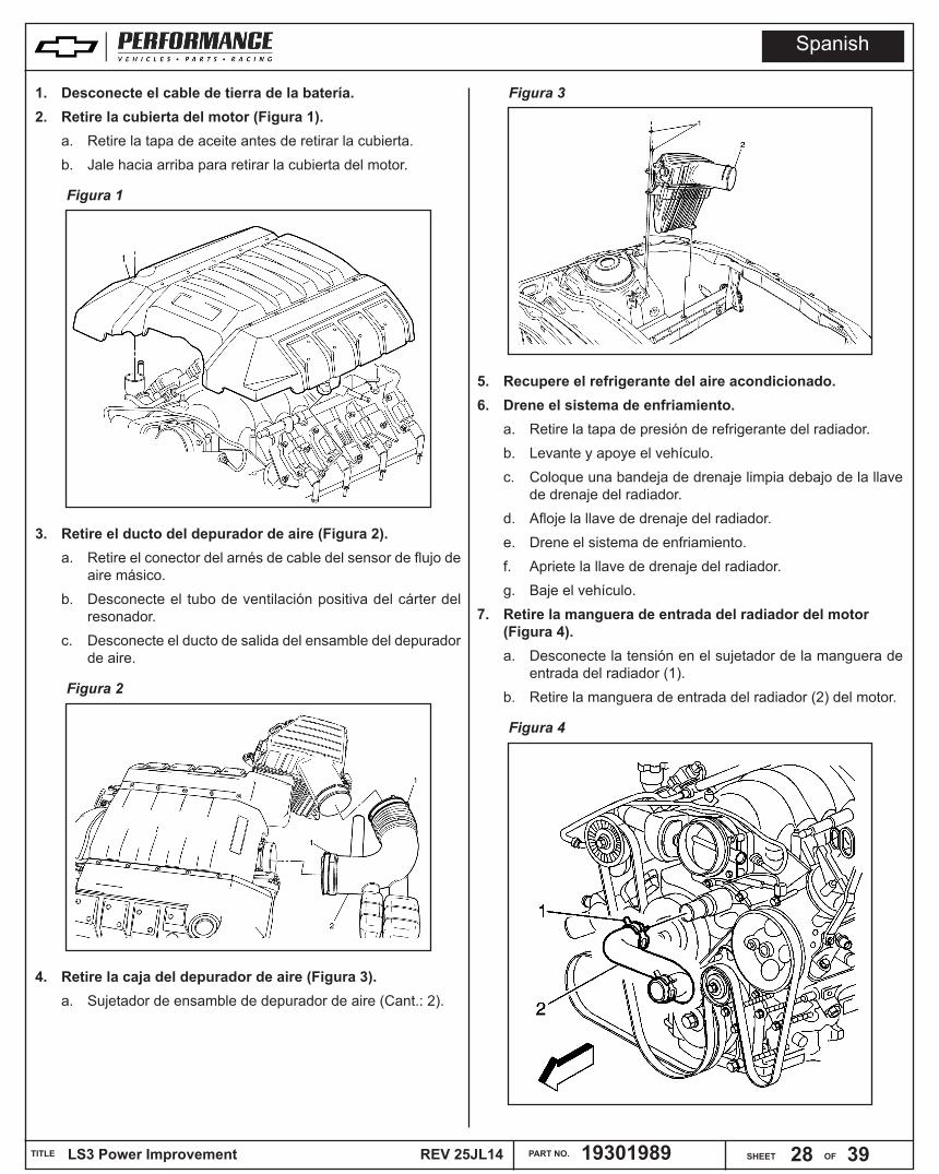
1. Desconecte el cable de tierra de la batería.2. Retire la cubierta del motor (Figura 1).
a. Retire la tapa de aceite antes de retirar la cubierta.b. Jale hacia arriba para retirar la cubierta del motor.
Figura 1
3. Retire el ducto del depurador de aire (Figura 2). a. Retire el conector del arnés de cable del sensor de flujo de
aire másico.b. Desconecte el tubo de ventilación positiva del cárter del
resonador. c. Desconecte el ducto de salida del ensamble del depurador
de aire.
Figura 2
4. Retire la caja del depurador de aire (Figura 3).a. Sujetador de ensamble de depurador de aire (Cant.: 2).
Figura 3
5. Recupere el refrigerante del aire acondicionado.6. Drene el sistema de enfriamiento.
a. Retire la tapa de presión de refrigerante del radiador.b. Levante y apoye el vehículo. c. Coloque una bandeja de drenaje limpia debajo de la llave
de drenaje del radiador.d. Afloje la llave de drenaje del radiador.e. Drene el sistema de enfriamiento.f. Apriete la llave de drenaje del radiador.g. Baje el vehículo.
7. Retire la manguera de entrada del radiador del motor (Figura 4). a. Desconecte la tensión en el sujetador de la manguera de
entrada del radiador (1). b. Retire la manguera de entrada del radiador (2) del motor.
Figura 4
Spanish

ALL INFORMATION WITHIN ABOVE BORDER TO BE PRINTED EXACTLY AS SHOWN ON 8 1/2 x 11 WHITE 16 POUND BOND PAPER. PRINT ON BOTH SIDES, EXCLUDING TEMPLATES.
TO BE UNITIZED IN ACCORDANCE WITH GM SPECIFICATIONS.
LS3 Power Improvement REV 25JL14TITLE PART NO. 19301989DATE AUTHREVISION
SHEET OF29 39
22OC13 Initial Release - Rocko Parker N/A 25JL14 Revision - Rocko Parker N/A
8. Retire la manguera de entrada del radiador del radiador (Figura 5). a. Desconecte la tensión en el sujetador de la manguera de
entrada del radiador (1) en el radiador. b. Retire la manguera de entrada del radiador (2) del radiador.
Figura 5
9. Retire la manguera de salida del radiador del motor (Figura 6). a. Desconecte la tensión en el sujetador de la manguera de
salida del radiador (1) en el motor. b. Retire la manguera de salida del radiador (2) del motor.
Figura 6
10. Retire la manguera de salida del radiador del radiador (Figura 7). a. Desconecte la tensión en el sujetador de la manguera de
salida del radiador (1).b. Retire la manguera de salida del radiador (2) del radiador.
Figura 7
11. Retire la manguera de purga de aire de refrigerante del motor (Figura 8).
Figura 8
12. Retire la manguera de sobreflujo del radiador (Figura 9).
Figura 9
Spanish

ALL INFORMATION WITHIN ABOVE BORDER TO BE PRINTED EXACTLY AS SHOWN ON 8 1/2 x 11 WHITE 16 POUND BOND PAPER. PRINT ON BOTH SIDES, EXCLUDING TEMPLATES.
TO BE UNITIZED IN ACCORDANCE WITH GM SPECIFICATIONS.
LS3 Power Improvement REV 25JL14TITLE PART NO. 19301989DATE AUTHREVISION
SHEET OF30 39
22OC13 Initial Release - Rocko Parker N/A 25JL14 Revision - Rocko Parker N/A
13. Retire la línea de aire acondicionado del condensador (Figura 10). a. Retire la tuerca del tubo de la válvula de expansión térmica
de evaporador de aire acondicionado (A/C) (1). b. Retire el tubo de la válvula de expansión térmica de
evaporador de aire acondicionado (A/C) (2) del condensador. Nota: Tape o cubra con cinta los componentes abiertos del aire acondicionado (A/C) de inmediato para prevenir contaminación del sistema.
Figura 10
14. Retire la línea de aire acondicionado del condensador (Figura 11). a. Retire la tuerca de la manguera del compresor de aire
acondicionado (A/C) (1).b. Retire la manguera del compresor de aire acondicionado
(A/C) (2) del condensador. Nota: Si está equipada, desconecte la manguera de salida del enfriador de fluido de la dirección hidráulica del enfriador de dirección hidráulica. Tape la manguera de salida del enfriador de la dirección hidráulica.
Figura 11
15. Retire el aro de refuerzo del ventilador de refrigerante del motor (Figura 12). a. Quite los tornillos (1).b. Retire el aro de refuerzo del ventilador (2).
Figura 12
16. Retire el ensamble del radiador (Figura 13). a. Retire el perno del soporte superior del radiador (1).b. Retire el soporte superior del radiador (2).
Figura 13
17. Retire la banda de impulso serpentina (Figura 14). a. Use la herramienta apropiada para girar el tensor de
la banda de impulso (1).b. Retire la banda de impulso de las poleas y el tensor (2).
Spanish

ALL INFORMATION WITHIN ABOVE BORDER TO BE PRINTED EXACTLY AS SHOWN ON 8 1/2 x 11 WHITE 16 POUND BOND PAPER. PRINT ON BOTH SIDES, EXCLUDING TEMPLATES.
TO BE UNITIZED IN ACCORDANCE WITH GM SPECIFICATIONS.
LS3 Power Improvement REV 25JL14TITLE PART NO. 19301989DATE AUTHREVISION
SHEET OF31 39
22OC13 Initial Release - Rocko Parker N/A 25JL14 Revision - Rocko Parker N/A
Figura 14
18. Retire las mangueras del calentador de la bomba de refrigerante (Figura 15). a. Retire la tensión de los sujetadores de la manguera (1).b. Retire el ensamble de la manguera de entrada y salida del
calentador (2).
Figura 15
19. Retire la bomba de refrigerante (Figura 16). a. Retire los pernos de la bomba de agua al bloque.
Figura 16
20. Retire la banda de la bomba de aire acondicionado (Figura 17). a. Retire los 4 pernos (1).b. Incline el compresor para liberar la tensión de la banda
y retírela.
Figura 17
21. Retire el balanceador armónico del motor. a. Retire el perno del balanceador del cigüeñal (Figura 18).
Figura 18
Spanish

ALL INFORMATION WITHIN ABOVE BORDER TO BE PRINTED EXACTLY AS SHOWN ON 8 1/2 x 11 WHITE 16 POUND BOND PAPER. PRINT ON BOTH SIDES, EXCLUDING TEMPLATES.
TO BE UNITIZED IN ACCORDANCE WITH GM SPECIFICATIONS.
LS3 Power Improvement REV 25JL14TITLE PART NO. 19301989DATE AUTHREVISION
SHEET OF32 39
22OC13 Initial Release - Rocko Parker N/A 25JL14 Revision - Rocko Parker N/A
b. No deseche el perno del balanceador del cigüeñal. El perno del balanceador se usará durante el procedimiento de instalación del balanceador.
c. Marque o realice una marca en el balanceador del cigüeñal y el extremo del cigüeñal (Figura 19).
Figura 19
d. Desconecte el conector eléctrico del arnés del motor (1) del conector eléctrico del arnés de cable del sensor de posición de árbol de levas (CMP).
e. Use el extractor del balanceador del cigüeñal (1) y el protector de extremo del cigüeñal (2) para retirar el balancedor del cigüeñal (Figura 20).
Figura 20
22. Retire la cubierta delantera del motor. a. Retire los pernos del cárter de aceite a la cubierta delantera
(1) (Figura 21).
Figura 21
b. Retire los pernos de la cubierta delantera (501), la cubierta delantera (502) y el empaque (503) (Figura 22).
Figura 22
23. Retire el múltiple de admisión del motor. a. Desconecte el conector eléctrico para los inyectores de
combustible. b. Desconecte los conectores eléctricos del cuerpo del
acelerador. c. Desconecte la alimentación de combustible para los
inyectores de combustible. d. Retire la manguera/tubería/tubo de ventilación positiva del
cárter. e. Retire la manguera de vacío del reforzador del freno.f. Desconecte el tubo de emisiones de evaporación.g. Desconecte el conector eléctrico del sensor de presión
absoluta del múltiple (MAP). h. Retire los pernos del múltiple de admisión (512) y el soporte
de paro del riel de combustible (712) (Figura 23).i. Retire el múltiple de admisión. j. Retire la línea de purga de aire entre las culatas de cilindro
(frente del motor).
Spanish

ALL INFORMATION WITHIN ABOVE BORDER TO BE PRINTED EXACTLY AS SHOWN ON 8 1/2 x 11 WHITE 16 POUND BOND PAPER. PRINT ON BOTH SIDES, EXCLUDING TEMPLATES.
TO BE UNITIZED IN ACCORDANCE WITH GM SPECIFICATIONS.
LS3 Power Improvement REV 25JL14TITLE PART NO. 19301989DATE AUTHREVISION
SHEET OF33 39
22OC13 Initial Release - Rocko Parker N/A 25JL14 Revision - Rocko Parker N/A
Figura 23
24. Desinstalación de bobina de ignición (Figura 24). a. Vuelva a colocar el arnés de cables del motor conforme
sea necesario.b. Desconecte los cables de la bujía (1) de las bobinas de
ignición. c. Retire el ensamble de la bobina de ignición a los pernos de
retención de la cubierta del balancín (2). d. Retire el ensamble de la bobina de ignición del motor.
Figura 24
25. Desinstalación de múltiple de escape (Figura 25). a. Retire los pernos y el empaque. Deseche el empaque
(Figura 24).b. Empuje el múltiple de escape para que no estorbe, para la
desinstalación de la culata.
Figura 25
26. Retire las cubiertas de la válvula (Figura 26). a. Retire los pernos de la cubierta del brazo de balancín de la
válvula (1) (Figura 26).b. Retire las cubiertas de la válvula (2).
Figura 26
a. Retire los brazos de balancín (Figura 27).
Spanish
ALL INFORMATION WITHIN ABOVE BORDER TO BE PRINTED EXACTLY AS SHOWN ON 8 1/2 x 11 WHITE 16 POUND BOND PAPER. PRINT ON BOTH SIDES, EXCLUDING TEMPLATES.
TO BE UNITIZED IN ACCORDANCE WITH GM SPECIFICATIONS.
LS3 Power Improvement REV 25JL14TITLE PART NO. 19301989DATE AUTHREVISION
SHEET OF34 39
22OC13 Initial Release - Rocko Parker N/A 25JL14 Revision - Rocko Parker N/A
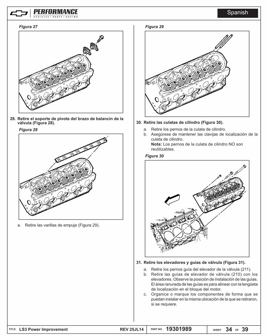
Figura 27
28. Retire el soporte de pivote del brazo de balancín de la válvula (Figura 28).Figura 28
a. Retire las varillas de empuje (Figura 29).
Figura 29
30. Retire las culatas de cilindro (Figura 30).a. Retire los pernos de la culata de cilindro. b. Asegúrese de mantener las clavijas de localización de la
culata de cilindro.Nota: Los pernos de la culata de cilindro NO son reutilizables.
Figura 30
31. Retire los elevadores y guías de válvula (Figura 31).a. Retire los pernos guía del elevador de la válvula (211). b. Retire las guías de elevador de válvula (210) con los
elevadores. Observe la posición de instalación de las guías. El área ranurada de las guías es para alinear con la lengüeta de localización en el bloque del motor.
c. Organice o marque los componentes de forma que se puedan instalar en la misma ubicación de la que se retiraron, si se requiere.
Spanish

ALL INFORMATION WITHIN ABOVE BORDER TO BE PRINTED EXACTLY AS SHOWN ON 8 1/2 x 11 WHITE 16 POUND BOND PAPER. PRINT ON BOTH SIDES, EXCLUDING TEMPLATES.
TO BE UNITIZED IN ACCORDANCE WITH GM SPECIFICATIONS.
LS3 Power Improvement REV 25JL14TITLE PART NO. 19301989DATE AUTHREVISION
SHEET OF35 39
22OC13 Initial Release - Rocko Parker N/A 25JL14 Revision - Rocko Parker N/A
Figura 31
32. Retire la rueda dentada del árbol de levas.a. Gire la rueda dentada del cigüeñal hasta que la marca de
alineación de la rueda dentada del cigüeñal (1) y la marca de alineación de la rueda dentada del cigüeñal (2) estén alineadas (Figura 32).
Figura 32
b. Retire el perno de la rueda dentada del árbol de levas (206) y la rueda dentada del árbol de levas (205) (Figura 33).Precaución: No gire el ensamble del árbol de levas después que se haya retirado la cadena de sincronización para prevenir daño a los ensambles del pistón o las válvulas.
Figura 33
33. Retire la placa de retención del árbol de levas (Figura 34).a. Retire los pernos del retenedor del árbol de levas (204) y
el retenedor (203).
Figura 34
34. Retire el árbol de levas (Figura 35).a. Instale el perno de la rueda dentada del árbol de levas en
el orificio del perno delantero del árbol de levas.b. Usando el perno como una manija, gire cuidadosamente y
retire el árbol de levas del bloque del motor. Precaución: Todos los muñones del árbol de levas tienen el mismo diámetro, así que se debe tener cuidado al retirar e instalar el árbol de levas para evitar daño a los cojinetes del árbol de levas.
Spanish

ALL INFORMATION WITHIN ABOVE BORDER TO BE PRINTED EXACTLY AS SHOWN ON 8 1/2 x 11 WHITE 16 POUND BOND PAPER. PRINT ON BOTH SIDES, EXCLUDING TEMPLATES.
TO BE UNITIZED IN ACCORDANCE WITH GM SPECIFICATIONS.
LS3 Power Improvement REV 25JL14TITLE PART NO. 19301989DATE AUTHREVISION
SHEET OF36 39
22OC13 Initial Release - Rocko Parker N/A 25JL14 Revision - Rocko Parker N/A
Figura 35
35. Las partes nuevas se instalan con el proceso inverso con la nueva información como sigue:
36. Tensor de cadena de sincronización (Figura 36):a. Comprima la guía del tensor de la cadena de sincronización
e instale el perno de retención.
Figura 36
37. Nueva rueda dentada de árbol de levas:a. El nuevo árbol de levas usa una conexión de tres pernos
contra el perno sencillo retirado.
b. Alinee la marca de alineación del árbol de levas en la posición de las 6 en punto (1) (Figura 37).
Figura 37
38. Retire el pasador de retención instalado previamente (Figura 38).
Figura 38
39. Secuencia de apriete de culata de cilindro (Figura 39).
Spanish
ALL INFORMATION WITHIN ABOVE BORDER TO BE PRINTED EXACTLY AS SHOWN ON 8 1/2 x 11 WHITE 16 POUND BOND PAPER. PRINT ON BOTH SIDES, EXCLUDING TEMPLATES.
TO BE UNITIZED IN ACCORDANCE WITH GM SPECIFICATIONS.
LS3 Power Improvement REV 25JL14TITLE PART NO. 19301989DATE AUTHREVISION
SHEET OF37 39
22OC13 Initial Release - Rocko Parker N/A 25JL14 Revision - Rocko Parker N/A
Figura 39
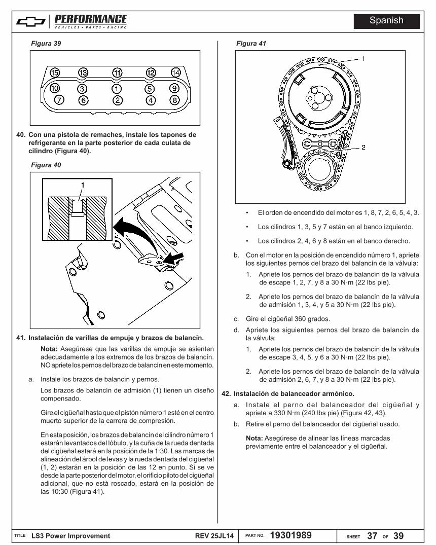
40. Con una pistola de remaches, instale los tapones de refrigerante en la parte posterior de cada culata de cilindro (Figura 40).
Figura 40
41. Instalación de varillas de empuje y brazos de balancín.Nota: Asegúrese que las varillas de empuje se asienten adecuadamente a los extremos de los brazos de balancín. NO apriete los pernos del brazo de balancín en este momento.
a. Instale los brazos de balancín y pernos. Los brazos de balancín de admisión (1) tienen un diseño compensado.
Gire el cigüeñal hasta que el pistón número 1 esté en el centro muerto superior de la carrera de compresión.
En esta posición, los brazos de balancín del cilindro número 1 estarán levantados del lóbulo, y la cuña de la rueda dentada del cigüeñal estará en la posición de la 1:30. Las marcas de alineación del árbol de levas y la rueda dentada del cigüeñal (1, 2) estarán en la posición de las 12 en punto. Si se ve desde la parte posterior del motor, el orificio piloto del cigüeñal adicional, que no está roscado, estará en la posición de las 10:30 (Figura 41).
Figura 41
• El orden de encendido del motor es 1, 8, 7, 2, 6, 5, 4, 3.
• Los cilindros 1, 3, 5 y 7 están en el banco izquierdo.
• Los cilindros 2, 4, 6 y 8 están en el banco derecho.
b. Con el motor en la posición de encendido número 1, apriete los siguientes pernos del brazo del balancín de la válvula: 1. Apriete los pernos del brazo de balancín de la válvula
de escape 1, 2, 7, y 8 a 30 N·m (22 lbs pie).
2. Apriete los pernos del brazo de balancín de la válvula de admisión 1, 3, 4, y 5 a 30 N·m (22 lbs pie).
c. Gire el cigüeñal 360 grados.d. Apriete los siguientes pernos del brazo de balancín de
la válvula:1. Apriete los pernos del brazo de balancín de la válvula
de escape 3, 4, 5, y 6 a 30 N·m (22 lbs pie).
2. Apriete los pernos del brazo de balancín de la válvula de admisión 2, 6, 7, y 8 a 30 N·m (22 lbs pie).
42. Instalación de balanceador armónico. a. Instale el perno del balanceador del cigüeñal y
apriete a 330 N·m (240 lbs pie) (Figura 42, 43). b. Retire el perno del balanceador del cigüeñal usado.
Nota: Asegúrese de alinear las líneas marcadas previamente entre el balanceador y el cigüeñal.
Spanish

ALL INFORMATION WITHIN ABOVE BORDER TO BE PRINTED EXACTLY AS SHOWN ON 8 1/2 x 11 WHITE 16 POUND BOND PAPER. PRINT ON BOTH SIDES, EXCLUDING TEMPLATES.
TO BE UNITIZED IN ACCORDANCE WITH GM SPECIFICATIONS.
LS3 Power Improvement REV 25JL14TITLE PART NO. 19301989DATE AUTHREVISION
SHEET OF38 39
22OC13 Initial Release - Rocko Parker N/A 25JL14 Revision - Rocko Parker N/A
Figura 42
Figura 43
Nota: La punta del cigüeñal debe estar hundida 2.4-4.48 mm (0.094-0.176 pulg.) dentro del barreno del balanceador.
c. Mida respecto a un balanceador instalado correctamente (Figura 44).
d. Instale el NUEVO perno del balanceador del cigüeñal (139).1. Apriete el perno del balanceador del cigüeñal a 80 N·m
(59 lbs pie).
2. Apriete el perno del balanceador del cigüeñal una pasada final a 125 grados.
Figura 44
43. Drene y reemplace el aceite y filtro del motor.44. Actualice el programa del módulo de control del motor
(ECM) conforme a las instrucciones al principio de este documento.
Número de parte de calibraciónCalibraciónTransmisiónMotorModeloModelo
1266124612661247
Diagnóstico de motorM10LS3Camaro SS2010
1266124912661251
Diagnóstico de motorM10LS3Camaro SS
Convertible2011
1266124812661250
Diagnóstico de motorM10LS3Camaro SS
Coupé2011
1266125212661253
Diagnóstico de motorM10LS3Camaro SS2012
1266125412661256
Diagnóstico de motorM10LS3Camaro SS2013
1266125512661256
Diagnóstico de motorMM6LS3Camaro 1LE2013
1266125712661259
Diagnóstico de motorM10LS3Camaro SS2014
1266125812661259
Diagnóstico de motorMM6LS3Camaro 1LE2014
1266647512666477
Diagnóstico de motorM10LS3Camaro SS2015
1266647612666477
Diagnóstico de motorMM6LS3Camaro 1LE2015
Spanish

ALL INFORMATION WITHIN ABOVE BORDER TO BE PRINTED EXACTLY AS SHOWN ON 8 1/2 x 11 WHITE 16 POUND BOND PAPER. PRINT ON BOTH SIDES, EXCLUDING TEMPLATES.
TO BE UNITIZED IN ACCORDANCE WITH GM SPECIFICATIONS.
LS3 Power Improvement REV 25JL14TITLE PART NO. 19301989DATE AUTHREVISION
SHEET OF39 39
22OC13 Initial Release - Rocko Parker N/A 25JL14 Revision - Rocko Parker N/A
Especificaciones de apriete de sujetador (6.2L LS3)
Aplicación
Especificación
MétricoSistema inglés
Perno de sensor de posición de árbol de levas (CMP) 10 N·m 89 lbs pulg.
Perno de arnés de cable de sensor CMP 10 N·m 89 lbs pulg.
Pernos de retención de árbol de levas - Pernos de cabeza hexagonal 25 N·m 18 lbs pie
Pernos de retención de árbol de levas - Pernos de cabeza TORX® 15 N·m 11 lbs pie
Perno de rueda dentada de árbol de levas 30 N·m 22 lbs pie
Sensor de temperatura del refrigerante 20 N·m 15 lbs piePerno de balanceador de cigüeñal - Pasa la instalación con perno usado - para asegurar que el balanceador esté instalado completamente
330 N·m 240 lbs pie
Perno de balanceador de cigüeñal - Perno nuevo
Paso 1 150 N·m 110 lbs piePaso 2 Afloje 360 gradosPaso 3 80 N·m 59 lb piePaso final 125 gradosPernos M11 de la culata de cilindro - Primera pasada en secuencia 30 N·m 22 lbs pie
Pernos M11 de la culata de cilindro - Segunda pasada en secuencia 90 grados
Pernos M11 de la culata de cilindro - Pasada final en secuencia 70 grados
Pernos M8 de culata de cilindro - en Secuencia 30 N·m 22 lbs pie
Tapón de refrigerante de culata de cilindro 20 N·m 15 lbs pie
Perno de válvula solenoide de purga de depósito de emisiones de evaporación (EVAP)
50 N·m 37 lbs pie
Pernos de múltiple de escape - Primera pasada 15 N·m 11 lbs pie
Pernos de múltiple de escape - Pasada final 20 N·m 15 lbs pie
Pernos de protección térmica de múltiple de escape 9 N·m 80 lbs pulg.
Perno del múltiple de escape 20 N·m 15 lbs piePernos de cubierta delantera 25 N·m 18 lbs piePernos de riel de combustible de inyección de combustible 10 N·m 89 lbs pulg.
Perno de soporte de bobina de ignición a cubierta de brazo de balancín de válvula 12 N·m 106 lbs pulg.
Especificaciones de apriete de sujetador (6.2L LS3)
Aplicación
Especificación
MétricoSistema inglés
Pernos de bobina de ignición al soporte 10 N·m 89 lbs pulg.Pernos de múltiple de admisión - Primera pasada en secuencia 5 N·m 44 lbs pulg.
Pernos de múltiple de admisión - Pasada final en secuencia 10 N·m 89 lbs pulg.
Filtro de aceite 30 N·m 22 lbs piePerno de tubo de indicador de nivel de aceite 25 N·m 18 lbs pie
Tapón de drenaje de cárter de aceite 25 N·m 18 lbs piePernos M6 de cárter de aceite - Cárter de aceite a Alojamiento de sello de aceite trasero
12 N·m 106 lbs pulg.
Pernos M8 del cárter de aceite - Cárter de aceite al bloque del motor y Cárter de aceite a cubierta delantera
25 N·m 18 lbs pie
Pernos de bomba de aceite a bloque de motor 25 N·m 18 lbs pie
Bujías 15 N·m 11 lbs piePernos de cuerpo de acelerador 10 N·m 89 lbs pulg.Pernos de tensor de cadena de sincronización 30 N·m 22 lbs pie
Pernos guía de elevador de válvula 12 N·m 106 lbs pulg.
Pernos de brazo de balancín de válvula 30 N·m 22 lbs piePernos de cubierta de brazo de balancín de válvula 12 N·m 106 lbs
pulg.Pernos de alojamiento de entrada de agua 15 N·m 11 lbs pie
Pernos de bomba de agua - Primera pasada 15 N·m 11 lbs pie
Pernos de bomba de agua - Pasada final 30 N·m 22 lbs pie
Pernos de depurador de aire a carrocería 10 N·m 89 lbs pulg.Sujetadores de depurador de aire 4 N·m 35 lbs pulg.Pernos de bomba de aire acondicionado 22 N·m 16 lb pieTuerca de tubo de válvula de expansión térmica de evaporador de aire acondicionado
22 N·m 16 lb pie
Tuerca de manguera de compresor de aire acondicionado 22 N·m 16 lb pie
Pernos de aro de refuerzo de ventilador del motor a ensamble del radiador
8 N·m 70 lbs pulg.
Perno de ménsula de soporte superior del radiador 9 N·m 80 lbs pulg.
Spanish