gemini™ 38aq007 38arq008,012 38aqs016 50/60...
TRANSCRIPT

Manufacturer reserves the right to discontinue, or change at any time, specifications or designs without notice and without incurring obligations.PC 111 Catalog No. 533-80118 Printed in U.S.A. 38A-19SI Pg 1 9-04 Replaces: 38A-16SIBook 1 4
Tab 5a 5a
Installation, Start-Up and Service InstructionsCONTENTS
PageSAFETY CONSIDERATIONS . . . . . . . . . . . . . . . . . . . . . . 1INSTALLATION . . . . . . . . . . . . . . . . . . . . . . . . . . . . . . . . 1-17General . . . . . . . . . . . . . . . . . . . . . . . . . . . . . . . . . . . . . . . . . . 1Step 1 — Complete Pre-Installation Checks . . . . . . 1Step 2 — Rig and Mount Unit. . . . . . . . . . . . . . . . . . . . . 1Step 3 — Complete Refrigerant Piping
Connections . . . . . . . . . . . . . . . . . . . . . . . . . . . . . . . . . . 10Step 4 — Complete Electrical Connections. . . . . . 11PRE-START-UP . . . . . . . . . . . . . . . . . . . . . . . . . . . . . . . 18, 19START-UP . . . . . . . . . . . . . . . . . . . . . . . . . . . . . . . . . . . . 19-21SEQUENCE OF OPERATION . . . . . . . . . . . . . . . . . 21, 22SERVICE . . . . . . . . . . . . . . . . . . . . . . . . . . . . . . . . . . . . . 22-27TROUBLESHOOTING. . . . . . . . . . . . . . . . . . . . . . . . . 28, 29START-UP CHECKLIST . . . . . . . . . . . . . . . . . . CL-1, CL-2
SAFETY CONSIDERATIONSInstalling, starting up, and servicing air-conditioning equip-
ment can be hazardous due to system pressures, electricalcomponents, and equipment location (roofs, elevated struc-tures, etc.).
Only trained, qualified installers and service mechanicsshould install, start-up, and service this equipment. Untrainedpersonnel can perform basic maintenance functions such ascleaning coils. All other operations should be performed bytrained service personnel.
When working on the equipment, observe precautions inthe literature and on tags, stickers, and labels attached to theequipment.
Follow all safety codes. Wear safety glasses and workgloves. Keep quenching cloth and fire extinguisher nearbywhen brazing. Use care in handling, rigging, and setting bulkyequipment.
INSTALLATION
General — The split system heat pump units described inthis book should only be used with the 40RMQ indoor pack-aged air handler sections.
Step 1 — Complete Pre-Installation ChecksUNCRATE UNIT — Remove unit packaging except for thetop skid assembly, which should be left in place until after theunit is rigged into its final location.INSPECT SHIPMENT — File claim with shipping companyif shipment is damaged or incomplete.
CONSIDER SYSTEM REQUIREMENTS• Consult local building codes and National Electrical
Code (NEC, U.S.A.) for special installation requirements.• Allow sufficient space for airflow clearance, wiring,
refrigerant piping, and servicing unit. See Fig. 1-3 forunit dimensions. Figure 4 shows typical component loca-tions for 38AQS016 units.
• Locate unit so that outdoor coil airflow is unrestricted onall sides and above.
• Unit may be mounted on a level pad directly on the basechannels or mounted on raised pads at support points.See Tables 1A-1D for unit operating weights.
Step 2 — Rig and Mount Unit
RIGGING — These units are designed for overhead rigging.Refer to rigging label for preferred rigging method. Spreaderbars are not required if top crating is left on unit. All panelsmust be in place when rigging. As further protection for coilfaces, plywood sheets may be placed against sides of unit,behind cables. Run cables to a central suspension point so thatangle from the horizontal is not less than 45 degrees. Raise andset unit down carefully.
If it is necessary to roll the unit into position, mount the uniton field-supplied rails placed lengthwise under the unit using aminimum of 3 rollers. Apply force to the rails, not the unit. Ifthe unit is to be skidded into position, place it on a large padand drag it by the pad. Do not apply any force to the unit.
Raise from above to lift unit from the rails or pad when unitis in final position.
After unit in position, remove all shipping materials and topcrating.LOCATE UNIT — For service access and unrestricted air-flow, provide clearance on each end and side of unit. Positionunit so that there is unrestricted airflow above unit.NOTE: Before mounting unit, remove holddown brackets andrelease skid.
If conditions or local codes require unit to be fastened topad, use the mounting holes in the base rails.MOUNT UNIT — The unit may be mounted on a solid, levelconcrete pad, on accessory mounting legs, or on field-suppliedraised supports at each mounting position. (Note that mountinghardware is field supplied.)
Bolt unit securely to pad or supports after unit is in positionand is level. Be sure to mount unit level to ensure proper oilreturn to compressors. Mounting holes on unit can be used tosecure unit to vibration isolators, if required.
Before installing or servicing system, always turn off mainpower to system and install lockout tag on disconnect.There may be more than one disconnect switch. Electricalshock can cause personal injury.
Be sure unit panels are securely in place prior to rigging.Be careful rigging, handling, and installing unit. Improperunit location can cause system malfunction and materialdamage. Inspect base rails for any shipping damage andmake sure they are fastened securely to unit before rigging.
GEMINI™38AQ007
38ARQ008,01238AQS016
Split System Heat Pumps50/60 Hz

2
1-1/2
38-1/2
1-1/2
TOP FRONT
33
35
33
38-1/2
Line & LowVoltage WiringEntrances
1-1/21-1/24-1/42-1/2
1-1/82-1/8
5-3/4
9-3/4
1-1/2
BOTTOM REAR
27
24
33
35
AB
D
C
7/84 PLACES
24 1/2
10
19 3/8
4 7/8
FRONT
CONTROL BOX
Fig. 1 — 38AQ007 Unit Dimensions
NOTES:1. All dimensions are in inches.2. Recommended clearance for proper airflow (local codes or jurisdictions may prevail):
Top — 60 in.Sides — 24 in. on 3 sides; one side may have 6-in. clearance. (Control box side should have24-in. clearance for service access.)
3. Corner Weights (lb): A = 86B = 84C = 92D = 90
3
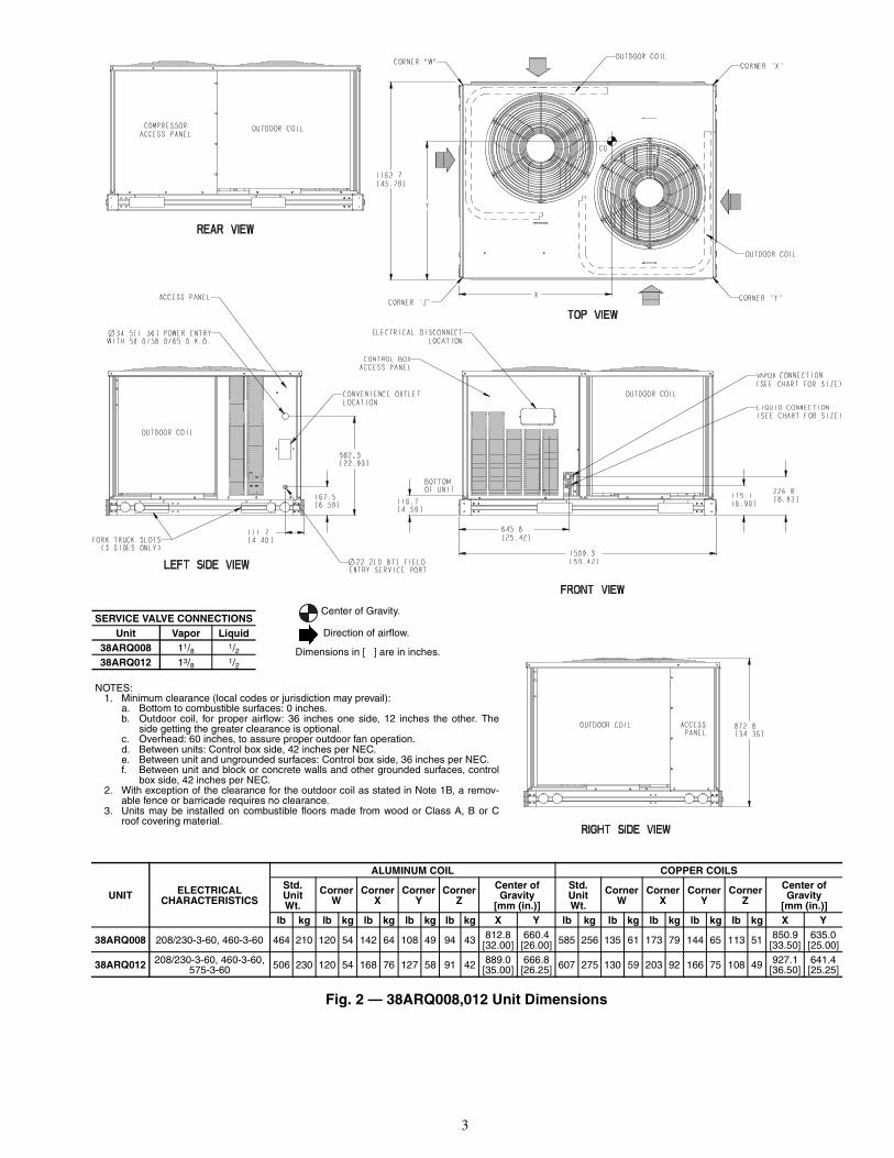
Fig. 2 — 38ARQ008,012 Unit Dimensions
UNIT ELECTRICALCHARACTERISTICS
ALUMINUM COIL COPPER COILSStd.UnitWt.
CornerW
CornerX
CornerY
CornerZ
Center ofGravity
[mm (in.)]
Std.UnitWt.
CornerW
CornerX
CornerY
CornerZ
Center ofGravity
[mm (in.)]lb kg lb kg lb kg lb kg lb kg X Y lb kg lb kg lb kg lb kg lb kg X Y
38ARQ008 208/230-3-60, 460-3-60 464 210 120 54 142 64 108 49 94 43 812.8[32.00]
660.4[26.00] 585 256 135 61 173 79 144 65 113 51 850.9
[33.50]635.0[25.00]
38ARQ012 208/230-3-60, 460-3-60,575-3-60 506 230 120 54 168 76 127 58 91 42 889.0
[35.00]666.8[26.25] 607 275 130 59 203 92 166 75 108 49 927.1
[36.50]641.4[25.25]
NOTES:1. Minimum clearance (local codes or jurisdiction may prevail):
a. Bottom to combustible surfaces: 0 inches.b. Outdoor coil, for proper airflow: 36 inches one side, 12 inches the other. The
side getting the greater clearance is optional.c. Overhead: 60 inches, to assure proper outdoor fan operation.d. Between units: Control box side, 42 inches per NEC.e. Between unit and ungrounded surfaces: Control box side, 36 inches per NEC.f. Between unit and block or concrete walls and other grounded surfaces, control
box side, 42 inches per NEC.2. With exception of the clearance for the outdoor coil as stated in Note 1B, a remov-
able fence or barricade requires no clearance.3. Units may be installed on combustible floors made from wood or Class A, B or C
roof covering material.
SERVICE VALVE CONNECTIONSUnit Vapor Liquid
38ARQ008 11/8 1/238ARQ012 13/8 1/2
Center of Gravity.
Direction of airflow.
Dimensions in [ ] are in inches.

4
Fig. 3 — 38AQS016 Unit Dimensions
NOTE: Recommended service clearances are asfollows (local codes or jurisdictions may prevail):Side (compressor) — 31/2 ft (1067 mm)Side (opposite compressor) — 3 ft (914 mm)Ends — 2 ft (616 mm)Top — 5 ft (1524 mm)
WEIGHT DISTRIBUTION
UNIT38AQS
WEIGHT — lb (kg)Total
OperatingWeight
Support Point
1 2 3 4
016 803(364)
158(72)
243(110)
244(111)
158(72)

5
1 2 3 4 5 6 7 8 9 10 11 12
13
14
15
16
17
1819202122232425
26
27
28
LEGEND
Fig. 4 — Component Locations — 38AQS016 Shown
1 — Defrost Board/Time Guard II Control 11 — Power Terminal Block 21 — Compressor2 — Fuse 12 — Control Terminal Block 22 — Capacity Control Solenoid3 — Fan No. 1 13 — Compressor Lockout (CLO2 for Crankcase Heater) 23 — Filter Drier4 — Compressor Lockout Device (CLO) 14 — Control Relay (CR3) 24 — Muffler5 — Outdoor-Fan Relay 15 — Liquid Line Solenoid 25 — Oil Solenoid6 — Outdoor-Fan Contactor 16 — Control Relay (CR2) 26 — Reversing Valve7 — Compressor Contactor 17 — No Dump Relay (NDR) 27 — Accumulator8 — Fan Motor Capacitors 18 — Oil Pressure Switch 28 — Coil9 — Circuit Breaker 19 — Fusible Plug (hidden)
10 — Fan No. 2 20 — High-Pressure Switch

6
Table 1A — Physical Data — 38AQ007, 38ARQ008,012, 38AQS016 Units — 60 Hz English
*Unit is factory supplied with holding charge only.†Typical operating charge with 25 ft of interconnecting pipe.**Storage capacity of condenser coil with 80% full of liquid at 95 F.
††Equipped with an electric solenoid unloader, capacity steps 100% and 67%.
UNIT 38AQ007 38ARQ008 38ARQ012 38AQS016NOMINAL CAPACITY (tons) 6 7.5 10 15OPERATING WEIGHTS (lb)
Aluminum-Fin Coils (standard) 345 464 506 803Copper-Fin Coils (optional) N/A 565 607 945
REFRIGERANT* R-22Operating Charge, Typical (lb)† 20 20 22 37Shipping Charge (lb) 1 9 9 3
COMPRESSOR Scroll Semi-hermeticreciprocating
Qty...Model 1...SR_75 1...ZR_94 1...ZR125 1...06DF537††Oil Charge (oz) 88 90 110 128No. Cylinders N/A 6Speed (rpm) 3500 1750
OUTDOOR FANSQty...Rpm 1…1100 2…1100 2…1075Diameter (in.) 26 22 26Nominal Hp 3/4 1/4 1/2Nominal Airflow (cfm total) 6300 6500 11,000Watts (total) 750 570 1460
OUTDOOR COILS (Qty) 1 2 1Face Area (sq ft total) 24 29.2 29.2Rows...Fins/in. 2…18 2…17 3…15Storage Capacity (lb)** 17.3 34.2 40.1
CONTROLSPressurestat Settings (psig)
High PressureOpen 420 428 ± 10 395 ± 20Close 300 320 ± 20 295 ± 20
Low PressureOpen 5 7 ± 3 7 ± 3Close 20 22 ± 5 22 ± 5
PIPING CONNECTIONS (in. ODM)Vapor 11/8 11/8 13/8 15/8Liquid 5/8 1/2 1/2 5/8
7
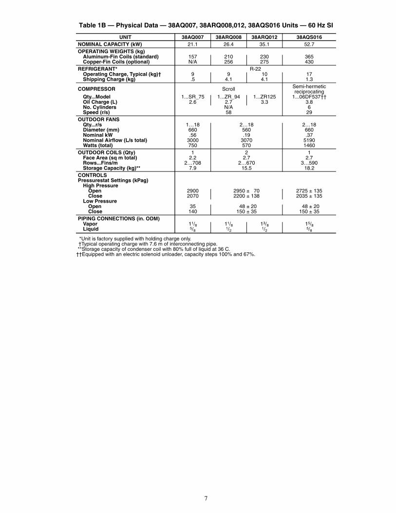
Table 1B — Physical Data — 38AQ007, 38ARQ008,012, 38AQS016 Units — 60 Hz SI
*Unit is factory supplied with holding charge only.†Typical operating charge with 7.6 m of interconnecting pipe.**Storage capacity of condenser coil with 80% full of liquid at 36 C.
††Equipped with an electric solenoid unloader, capacity steps 100% and 67%.
UNIT 38AQ007 38ARQ008 38ARQ012 38AQS016NOMINAL CAPACITY (kW) 21.1 26.4 35.1 52.7OPERATING WEIGHTS (kg)
Aluminum-Fin Coils (standard) 157 210 230 365Copper-Fin Coils (optional) N/A 256 275 430
REFRIGERANT* R-22Operating Charge, Typical (kg)† 9 9 10 17Shipping Charge (kg) .5 4.1 4.1 1.3
COMPRESSOR Scroll Semi-hermeticreciprocating
Qty...Model 1...SR_75 1...ZR_94 1...ZR125 1...06DF537††Oil Charge (L) 2.6 2.7 3.3 3.8No. Cylinders N/A 6Speed (r/s) 58 29
OUTDOOR FANSQty...r/s 1…18 2…18 2…18Diameter (mm) 660 560 660Nominal kW .56 .19 .37Nominal Airflow (L/s total) 3000 3070 5190Watts (total) 750 570 1460
OUTDOOR COILS (Qty) 1 2 1Face Area (sq m total) 2.2 2.7 2.7Rows...Fins/m 2…708 2…670 3…590Storage Capacity (kg)** 7.9 15.5 18.2
CONTROLSPressurestat Settings (kPag)
High PressureOpen 2900 2950 ± 70 2725 ± 135Close 2070 2200 ± 138 2035 ± 135
Low PressureOpen 35 48 ± 20 48 ± 20Close 140 150 ± 35 150 ± 35
PIPING CONNECTIONS (in. ODM)Vapor 11/8 11/8 13/8 15/8Liquid 5/8 1/2 1/2 5/8

8
Table 1C — Physical Data — 38ARQ008,012 and 38AQS016 Units — 50 Hz English
*Unit is factory supplied with holding charge only.†Typical operating charge with 25 ft of interconnecting pipe.**Storage capacity of condenser coil with 80% full of liquid at 95 F.
††Equipped with an electric solenoid unloader, capacity steps 100% and 67%.
UNIT 38ARQ008 38ARQ012 38AQS016NOMINAL CAPACITY (tons) 6.3 8.3 12.5OPERATING WEIGHTS (lb)
Aluminum-Fin Coils (standard) 464 506 803Copper-Fin Coils (optional) 565 607 945
REFRIGERANT* R-22Operating Charge, Typical (lb)† 20 22 37Shipping Charge (lb) 9 9 3
COMPRESSOR Scroll Semi-hermeticreciprocating
Qty...Model 1...ZR_94 1...ZR125 1...06DF537††Oil Charge (oz) 90 110 128No. Cylinders N/A 6Speed (rpm) 2900 2900 1450
OUTDOOR FANSQty...Rpm 2…920 2…900Diameter (in.) 22 26Nominal Hp 1/4 1/2Nominal Airflow (cfm total) 5800 7400
OUTDOOR COILS (Qty) 2 1Face Area (sq ft total) 29.2 29.2Rows...Fins/in. 2…17 3…15Storage Capacity (lb)** 34.2 40.1
CONTROLSPressurestat Settings (psig)
High PressureOpen 428 ± 10 395 ± 20Close 320 ± 20 295 ± 20
Low PressureOpen 7 ± 3 7 ± 3Close 22 ± 5 22 ± 5
PIPING CONNECTIONS (in. ODM)Vapor 11/8 13/8 15/8Liquid 1/2 1/2 5/8
9
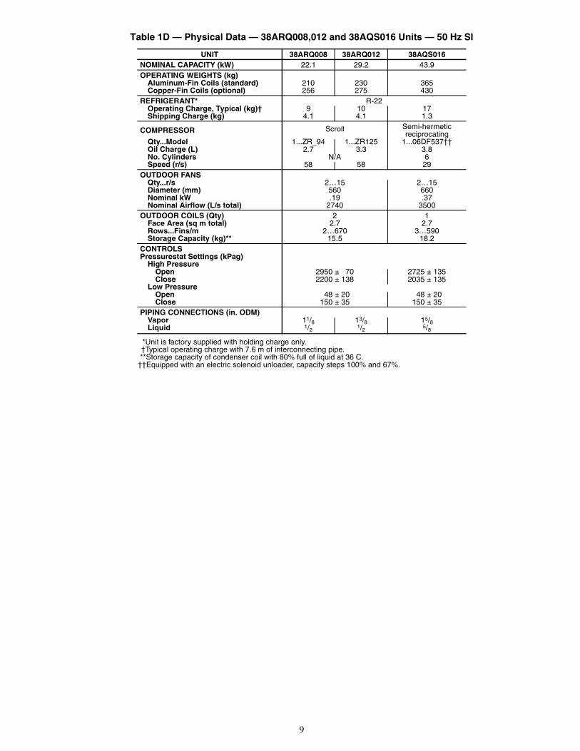
Table 1D — Physical Data — 38ARQ008,012 and 38AQS016 Units — 50 Hz SI
*Unit is factory supplied with holding charge only.†Typical operating charge with 7.6 m of interconnecting pipe.**Storage capacity of condenser coil with 80% full of liquid at 36 C.
††Equipped with an electric solenoid unloader, capacity steps 100% and 67%.
UNIT 38ARQ008 38ARQ012 38AQS016NOMINAL CAPACITY (kW) 22.1 29.2 43.9OPERATING WEIGHTS (kg)
Aluminum-Fin Coils (standard) 210 230 365Copper-Fin Coils (optional) 256 275 430
REFRIGERANT* R-22Operating Charge, Typical (kg)† 9 10 17Shipping Charge (kg) 4.1 4.1 1.3
COMPRESSOR Scroll Semi-hermeticreciprocating
Qty...Model 1...ZR_94 1...ZR125 1...06DF537††Oil Charge (L) 2.7 3.3 3.8No. Cylinders N/A 6Speed (r/s) 58 58 29
OUTDOOR FANSQty...r/s 2…15 2…15Diameter (mm) 560 660Nominal kW .19 .37Nominal Airflow (L/s total) 2740 3500
OUTDOOR COILS (Qty) 2 1Face Area (sq m total) 2.7 2.7Rows...Fins/m 2…670 3…590Storage Capacity (kg)** 15.5 18.2
CONTROLSPressurestat Settings (kPag)
High PressureOpen 2950 ± 70 2725 ± 135Close 2200 ± 138 2035 ± 135
Low PressureOpen 48 ± 20 48 ± 20Close 150 ± 35 150 ± 35
PIPING CONNECTIONS (in. ODM)Vapor 11/8 13/8 15/8Liquid 1/2 1/2 5/8
10
Step 3 — Complete Refrigerant Piping Con-nections — Refrigerant lines must be carefully designedand constructed to ensure equipment reliability and efficiency.Line length, pressure drop, compressor oil return, and verticalseparation are several of the design criteria that must be evalu-ated. See Table 2.
CHECK VERTICAL SEPARATION — If there is any verti-cal separation between the indoor and outdoor units, check toensure that the separation is within allowable limits. Relocateequipment if necessary. See Table 3.REFRIGERANT LINE SIZING — Consider the length ofthe piping required between the outdoor and indoor units. Themaximum allowable line length is 100 ft (30.5 m). See Table 2.Refrigerant vapor piping should be insulated.
Table 2 — Refrigerant Piping Sizes
LEGEND
*If there is a vertical separation between indoor and outdoor units, seeTable 3 — Maximum Vertical Separation.
NOTE: Approximately 4 elbows assumed in determining pipe sizes. Max-imum length of interconnecting piping is 100 ft (30.5 m).
Table 3 — Maximum Vertical Separation*
*Vertical distance between indoor and outdoor units.
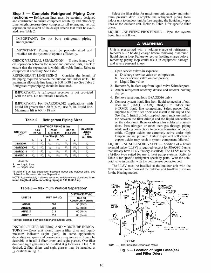
INSTALL FILTER DRIER(S) AND MOISTURE INDICA-TOR(S) — Every unit should have a filter drier and liquid-moisture indicator (sight glass). In some applications,depending on space and convenience requirements, it may bedesirable to install 2 filter driers and sight glasses. One filterdrier and sight glass may be installed at A locations in Fig. 5. Ifdesired, 2 filter driers and sight glasses may be installed atB locations in Fig. 5.
Select the filter drier for maximum unit capacity and mini-mum pressure drop. Complete the refrigerant piping fromindoor unit to outdoor unit before opening the liquid and vaporlines at the outdoor unit. Refer to Table 4 for specific filterdriers.LIQUID LINE PIPING PROCEDURE — Pipe the systemliquid line as follows:
1. Open service valves in sequence:a. Discharge service valve on compressor.b. Vapor service valve on compressor.c. Liquid line valve.
2. Remove 1/4-in. flare cap from liquid valve Schrader port.3. Attach refrigerant recovery device and recover holding
charge.4. Remove runaround loop (38AQS016 only).5. Connect system liquid line from liquid connection of out-
door unit (38AQ, 38ARQ, 38AQS) to indoor unit(40RMQ) liquid line connections. Select proper field-supplied bi-flow filter driers and install in the liquid line.See Fig. 5. Install a field-supplied liquid moisture indica-tor between the filter drier(s) and the liquid connectionson the indoor unit. Braze or silver alloy solder all connec-tions. Pass nitrogen or other inert gas through pipingwhile making connections to prevent formation of copperoxide. (Copper oxides are extremely active under hightemperature and pressure. Failure to prevent collection ofcopper oxides may result in system component failures.)
LIQUID LINE SOLENOID VALVE — Addition of a liquidsolenoid valve (LLSV) is required (except for 38AQS016 unitsthat already have LLSV factory-installed). The LLSV must bea bi-flow type suited for use in heat pump systems. Refer toTable 4 for specific refrigerant specialty parts. Wire the sole-noid valve in parallel with the compressor contactor coil.
The LLSV must be installed at the outdoor unit with theflow arrow pointed toward the outdoor unit (in-flow directionfor the Heating mode).
IMPORTANT: Do not bury refrigerant pipingunderground.
IMPORTANT: Piping must be properly sized andinstalled for the system to operate efficiently.
IMPORTANT: A refrigerant receiver is not providedwith the unit. Do not install a receiver.
IMPORTANT: For 38ARQ008,012 applications withliquid lift greater than 20 ft (6 m), use 5/8-in. liquid line.Maximum lift is 60 ft (18 m).
OUTDOORUNIT
LENGTH OF PIPING ft (m)MAXIMUM
LIQUIDLINE*
(in. OD)
0-25(0-7.5)
26-60(7.8-18.0)
61-100(18.3-30)
Line Size (in. OD)L V L V L V
38AQ007 1/2 11/8 5/8 11/8 5/8 11/8 5/838ARQ008 3/8 11/8 1/2 11/8 1/2 11/8 5/838ARQ012 1/2 13/8 1/2 13/8 1/2 13/8 5/838AQS016 5/8 15/8 3/4 15/8 3/4 15/8 3/4
L — Liquid LineV — Vapor Line
UNIT 38 UNIT 40RMQDISTANCE FT (M)
Unit 38Above Unit 40RMQ
AQ007 008 50 (15.2)ARQ008 008 60 (18.3)ARQ012 012 60 (18.3)AQS016 016 80 (24.4)
Unit is pressurized with a holding charge of refrigerant.Recover R-22 holding charge before removing runaroundliquid piping loop. Failure to recover holding charge beforeremoving piping loop could result in equipment damageand severe personal injury.
LEGEND
Fig. 5 — Location of Sight Glass(es)and Filter Driers
TXV — Thermostatic Expansion Valve

11
Table 4 — Refrigerant Specialties Part Numbers
*A filter drier is shipped loose with the 38AQ007.†Bushings required.
**Factory Installed.
PROVIDE SAFETY RELIEF — A fusible plug is located onthe compressor crankcase or in the liquid line. See Fig. 6. Donot cap this plug. If local code requires additional safetydevices, install them as directed.Head Pressure Control (38AQS016 Only) — Fan cycling forhead pressure control is a standard offering but is functional inthe cooling cycle only. Number 2 fan cycles as a function ofliquid pressure. Fan cycling pressure switch cycles the fan offat 160 ± 10 psig (1103 ± 69 kPag) as pressure decreases andcycles back on at 255 ± 10 psig (1758 ± 69). Switch is automat-ically bypassed in heating cycle. Table 5 shows minimum out-door air temperature for full cooling capacity without lowambient controls.
Table 5 — Minimum Outdoor AirOperating Temperature
*Applies to Cooling mode of operation only.†Wind baffles (field-supplied and field-installed) are recommended
for all units with low ambient head pressure control. Refer to LowAmbient Control Installation Instructions (shipped with accessory)for details.
VAPOR LINE PIPING PROCEDURE — Connect systemvapor line to the vapor line stub on the outdoor unit and thevapor stubs on the indoor unit. At the indoor unit, constructvapor piping branches as shown in Fig. 7 for good mixingof the refrigerant leaving the indoor coil during cooling. Thiswill ensure proper TXV (thermostatic expansion valve) bulbsensing.
Where vapor line is exposed to outdoor air, line must beinsulated. See Table 6 for insulation requirements.
Table 6 — Insulation for Vapor Line Exposedto Outdoor Conditions
*Recommended vapor line insulation for piping exposed to outdoorconditions to prevent loss of heating during heating cycle. Whenvapor line goes through interior spaces, insulation should beselected to prevent condensation on cooling cycle. Heating capacityshould be reduced 1000 Btuh (295 W) if over 35 ft (11 m) of vaporline with 3/4 in. (19 mm) insulation is exposed to outdoor conditions.
†Closed cell foam insulation with a thermal conductivity of: 0.28 Btu• in./ft2 • h • °F (0.04 W/m • °C).
Step 4 — Complete Electrical ConnectionsPOWER SUPPLY — Electrical characteristics of availablepower supply must agree with nameplate rating. Supplyvoltage must be within tolerances shown in Table 7. Phaseimbalance must not exceed 2%. Operation of unit on impropersupply voltage or with excessive phase imbalance constitutesabuse and is not covered by Carrier warranty.
UNIT LIQUID LINESIZE
LIQUID LINESOLENOID VALVE (LLSV) LLSV COIL SIGHT GLASS FILTER DRIER
38AQ0071/2″ 200RB GS-1928 5T4 AMG-24/50-60 AMI-1TT4 *5/8″ 200RB GS-1929 5T5 AMG-24/50-60 AMI-1TT5 *
38ARQ0083/8″ 200RB GS-1928 5T4† AMG-24/50-60 AMI-1TT3 P504-8083S1/2″ 200RB GS-1928 5T4 AMG-24/50-60 AMI-1TT4 P504-8084S
38ARQ012 1/2″ 200RB GS-1928 5T4 AMG-24/50-60 AMI-1TT4 P504-8164S
38AQS0165/8″ ** ** AMI-1TT5 P504-8085S Qty 23/4″ ** ** AMI-1TT5 P504-8085S Qty 2
UNIT38
%COMPRESSOR
CAPACITY
MINIMUM OUTDOORTEMP — F (C)*
Standard Unit Head PressureControl†
AQ 007100
0 (–17.8) 0 (–17.8)
ARQ008 35 (1.7) –20 (–28.9)012 35 (1.7) –20 (–28.9)
AQS 016 10067
23 (–5)36 (2.2)
–20 (–28.9)–20 (–28.9)
LENGTH OF EXPOSEDVAPOR LINE* INSULATION THICKNESS†
ft m in. mm10 3 3/8 10
25 8 1/2 13
35 11 3/4 19
50 15 3/4 19
Fig. 6 — Location of Fusible Plug —38AQS016 Unit
LEGEND
Fig. 7 — Vapor Line Branch Piping Details
TXV — Thermostatic Expansion Valve
12
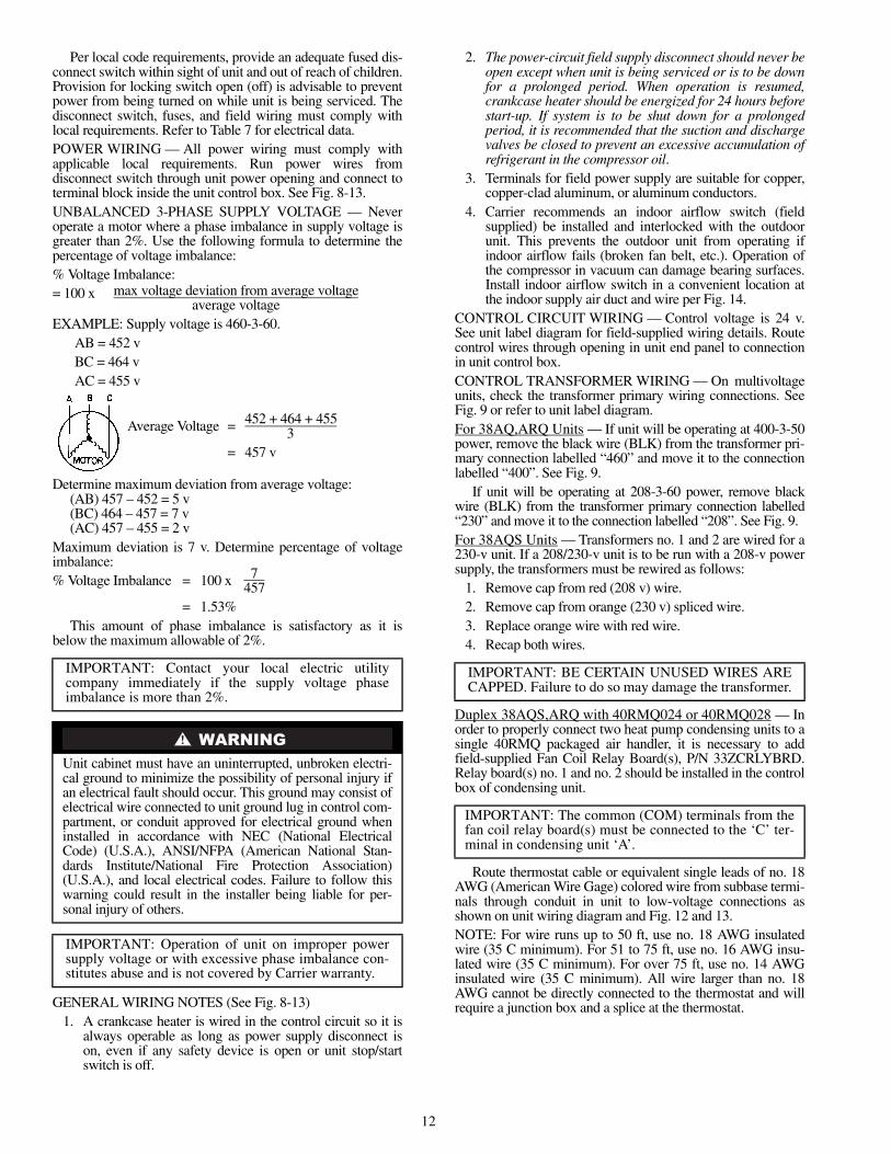
Per local code requirements, provide an adequate fused dis-connect switch within sight of unit and out of reach of children.Provision for locking switch open (off) is advisable to preventpower from being turned on while unit is being serviced. Thedisconnect switch, fuses, and field wiring must comply withlocal requirements. Refer to Table 7 for electrical data.POWER WIRING — All power wiring must comply withapplicable local requirements. Run power wires fromdisconnect switch through unit power opening and connect toterminal block inside the unit control box. See Fig. 8-13.UNBALANCED 3-PHASE SUPPLY VOLTAGE — Neveroperate a motor where a phase imbalance in supply voltage isgreater than 2%. Use the following formula to determine thepercentage of voltage imbalance:% Voltage Imbalance:= 100 x max voltage deviation from average voltage
average voltageEXAMPLE: Supply voltage is 460-3-60.
AB = 452 vBC = 464 vAC = 455 v
Average Voltage = 452 + 464 + 4553
= 457 v
Determine maximum deviation from average voltage:(AB) 457 – 452 = 5 v(BC) 464 – 457 = 7 v(AC) 457 – 455 = 2 v
Maximum deviation is 7 v. Determine percentage of voltageimbalance:% Voltage Imbalance = 100 x 7
457= 1.53%
This amount of phase imbalance is satisfactory as it isbelow the maximum allowable of 2%.
GENERAL WIRING NOTES (See Fig. 8-13)1. A crankcase heater is wired in the control circuit so it is
always operable as long as power supply disconnect ison, even if any safety device is open or unit stop/startswitch is off.
2. The power-circuit field supply disconnect should never beopen except when unit is being serviced or is to be downfor a prolonged period. When operation is resumed,crankcase heater should be energized for 24 hours beforestart-up. If system is to be shut down for a prolongedperiod, it is recommended that the suction and dischargevalves be closed to prevent an excessive accumulation ofrefrigerant in the compressor oil.
3. Terminals for field power supply are suitable for copper,copper-clad aluminum, or aluminum conductors.
4. Carrier recommends an indoor airflow switch (fieldsupplied) be installed and interlocked with the outdoorunit. This prevents the outdoor unit from operating ifindoor airflow fails (broken fan belt, etc.). Operation ofthe compressor in vacuum can damage bearing surfaces.Install indoor airflow switch in a convenient location atthe indoor supply air duct and wire per Fig. 14.
CONTROL CIRCUIT WIRING — Control voltage is 24 v.See unit label diagram for field-supplied wiring details. Routecontrol wires through opening in unit end panel to connectionin unit control box.CONTROL TRANSFORMER WIRING — On multivoltageunits, check the transformer primary wiring connections. SeeFig. 9 or refer to unit label diagram.For 38AQ,ARQ Units — If unit will be operating at 400-3-50power, remove the black wire (BLK) from the transformer pri-mary connection labelled “460” and move it to the connectionlabelled “400”. See Fig. 9.
If unit will be operating at 208-3-60 power, remove blackwire (BLK) from the transformer primary connection labelled“230” and move it to the connection labelled “208”. See Fig. 9.For 38AQS Units — Transformers no. 1 and 2 are wired for a230-v unit. If a 208/230-v unit is to be run with a 208-v powersupply, the transformers must be rewired as follows:
1. Remove cap from red (208 v) wire.2. Remove cap from orange (230 v) spliced wire.3. Replace orange wire with red wire.4. Recap both wires.
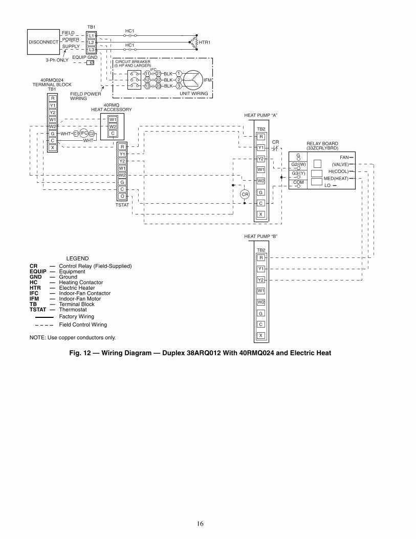
Duplex 38AQS,ARQ with 40RMQ024 or 40RMQ028 — Inorder to properly connect two heat pump condensing units to asingle 40RMQ packaged air handler, it is necessary to addfield-supplied Fan Coil Relay Board(s), P/N 33ZCRLYBRD.Relay board(s) no. 1 and no. 2 should be installed in the controlbox of condensing unit.
Route thermostat cable or equivalent single leads of no. 18AWG (American Wire Gage) colored wire from subbase termi-nals through conduit in unit to low-voltage connections asshown on unit wiring diagram and Fig. 12 and 13.NOTE: For wire runs up to 50 ft, use no. 18 AWG insulatedwire (35 C minimum). For 51 to 75 ft, use no. 16 AWG insu-lated wire (35 C minimum). For over 75 ft, use no. 14 AWGinsulated wire (35 C minimum). All wire larger than no. 18AWG cannot be directly connected to the thermostat and willrequire a junction box and a splice at the thermostat.
IMPORTANT: Contact your local electric utilitycompany immediately if the supply voltage phaseimbalance is more than 2%.
Unit cabinet must have an uninterrupted, unbroken electri-cal ground to minimize the possibility of personal injury ifan electrical fault should occur. This ground may consist ofelectrical wire connected to unit ground lug in control com-partment, or conduit approved for electrical ground wheninstalled in accordance with NEC (National ElectricalCode) (U.S.A.), ANSI/NFPA (American National Stan-dards Institute/National Fire Protection Association)(U.S.A.), and local electrical codes. Failure to follow thiswarning could result in the installer being liable for per-sonal injury of others.
IMPORTANT: Operation of unit on improper powersupply voltage or with excessive phase imbalance con-stitutes abuse and is not covered by Carrier warranty.
IMPORTANT: BE CERTAIN UNUSED WIRES ARECAPPED. Failure to do so may damage the transformer.
IMPORTANT: The common (COM) terminals from thefan coil relay board(s) must be connected to the ‘C’ ter-minal in condensing unit ‘A’.

13
Table 7 — Electrical Data
LEGEND
*Units are suitable for use on electrical systems where voltage suppliedto the unit terminals is not below or above the listed limits.
NOTES:1. The MCA and MOCP values are calculated in accordance with the
NEC, Article 440.2. Motor RLA and LRA values are established in accordance with
Underwriters’ Laboratories (UL), Standard 1995.3. The 575-v units are UL, Canada-listed only.4. Convenience outlet is available as factory-installed option only and
is 115-v, 1 ph, 60 Hz.
UNIT38
FACTORY-INSTALLEDOPTION
NOMINAL VOLTAGE(V-Ph-Hz)
VOLTAGE RANGE* COMPRESSOR FAN MOTORS POWER SUPPLYMin Max RLA LRA FLA MCA MOCP
AQ007 NONE208/230-3-60 187 253 18.9 146 5.1 28.7 45
460-3-60 414 506 9.5 73 2.6 14.5 20575-3-60 517 633 7.6 58 1.2 10.7 15
ARQ008
NONE OR DISCONNECT208/230-3-60 187 254 29.0 190 1.5
39.0 60CONVENIENCE OUTLET 43.8 60NONE OR DISCONNECT
460-3-60 418 506 15.0 95 0.719.8 30
CONVENIENCE OUTLET 21.9 30NONE OR DISCONNECT 400-3-50 360 440 15.0 95 0.7 19.8 30
ARQ012
NONE OR DISCONNECT208/230-3-60 187 254 34.0 225 1.5
45.0 60CONVENIENCE OUTLET 50.0 70NONE OR DISCONNECT
460-3-60 418 506 17.0 114 0.723.0 30
CONVENIENCE OUTLET 25.0 30NONE OR DISCONNECT
575-3-60 523 632 14.0 80 0.718.0 25
CONVENIENCE OUTLET 20.0 25NONE OR DISCONNECT 400-3-50 360 440 17.2 125 0.7 22.9 30
AQS016NONE
208/230-3-60 187 253 63.6 266 4.3 87.5 125460-3-60 414 528 29.3 120 2.3 40.7 60575-3-60 518 660 23.8 96 1.8 33.0 50
NONE230-3-50 198 264 47.9 200 3.5 66.9 100400-3-50 342 457 29.3 115 3.5 43.0 60
FLA — Full Load AmpsLRA — Locked Rotor AmpsMCA — Minimum Circuit AmpsMOCP — Maximum Overcurrent ProtectionNEC — National Electrical Code (U.S.A. Standard)RLA — Rated Load Amps
Fig. 8 — Wiring Diagram — 38AQ007 208/230-3-60 Units
LEGENDDF — Defrost RelayLP/HP — Low- or High-Pressure Switch (Optional)PS — Pressure SwitchRV — Reversing ValveSEN — Outdoor Coil Temperature SensorTSTAT — Thermostat
Line Voltage Factory WiringLow Voltage Factory WiringLow Voltage Field Wiring
COLOR CODE
NOTES:1. All electrical work must be done in conformance with the
National Electrical Code (NFPA No. 70) and in conformancewith local codes and authorities having jurisdiction.
2. For use with copper conductors only.
BK BlackBL BlueO OrangeR RedW WhiteY Yellow
Not suitable for use on systems exceeding 150 volts to ground.
RV
Y
BK
Y
CCBL
BK
PS2
Y
DF
C
PS1
O WR
BK
Y-RVDEFROSTCONTROL
BK
BL
R-RV
FAN RVCOIL
SEN
DEFROST HEAT
COMPRESSOR
HEAT/COOL
COMMON
WY
O
BL
LP/HP
LP/HP
FROMTSTAT
24 VACR

14
Fig. 9 — Wiring Diagram — 38ARQ008,012 — Control Transformer
Fig. 10 — Wiring Diagram — 38ARQ008,012 230-3-60 Units
W2
G
C
R
Y
O
E
1
2
3
4
5
6
7
8TO ELECTRICHEATERACCESSORY,IF EQUIPPED
IFC LLSV
THERMOSTATCONNECTIONBOARD (TB)
LEGENDIFC — Indoor Fan ContactorLLSV — Liquid Line Solenoid ValveTB — Terminal Block
NOTES:1. For thermostat and subbase part no. see
price pages.2. Use copper conductors only.

15
LEGENDEQUIP — EquipmentGND — GroundHC — Heater ContactorIFC — Indoor Fan ContactorIFM — Indoor Fan MotorNEC — National Electrical Code (U.S.A.)TB — Terminal Block
Fig. 11 — Wiring Diagram — 38AQS016 Unit With Standard Thermostat and Electric Heat
16
TB2
HEAT PUMP “A”
TB2
HEAT PUMP “B”
G2/(W)
G3/(Y)
COM
G
MED(HEAT)
HI(COOL)
(VALVE)
FAN
LO
R
Y1
Y2
W1
W2
G
C
O
WHT
WHT
C2IFCC1
R
Y1
Y2
W1
W2
G
C
X
40RMQHEAT ACCESSORY
W1
W2
C
40RMQ024TERMINAL BLOCK
TB1FIELD POWERWIRING
DISCONNECT
FIELD
POWER
SUPPLY
3-Ph ONLY
L1
L2
L3
EQUIP GND
TB1
HC1
HC1
CIRCUIT BREAKER(5 HP AND LARGER)
UNIT WIRING
IFMBLKBLKBLK
212223
1213
11 123
HTR1
IFC
RELAY BOARD(33ZCRLYBRD)
TSTAT
CR
Y2
R
Y1
C
X
W1
W2
G
Y2
R
Y1
C
X
W1
W2
G
CR
LEGEND
NOTE: Use copper conductors only.
CR — Control Relay (Field-Supplied)EQUIP — EquipmentGND — GroundHC — Heating ContactorHTR — Electric HeaterIFC — Indoor-Fan ContactorIFM — Indoor-Fan MotorTB — Terminal BlockTSTAT — Thermostat
Factory Wiring
Field Control Wiring
Fig. 12 — Wiring Diagram — Duplex 38ARQ012 With 40RMQ024 and Electric Heat

17
Y2
TB2
HEAT PUMP A38AQS016
R
B
W1
A2
Y1
Q
C
P
X
1
2
TB2
HEAT PUMP B38ARQ012
G2/(W)
G3/(Y)
COM
G
MED(HEAT)
HI(COOL)
(VALVE)
FAN
LO
G2/(W)
G3/(Y)
COM
G
MED(HEAT)
HI(COOL)
(VALVE)
FAN
LO
R
Y1
Y2
W1
W2
G
C
X
WHT
WHT
C2IFCC1
R
Y1
Y2
W1
W2
G
C
X
40RMQHEAT ACCESSORY
W1
W2
C
40RMQ028TERMINAL BLOCK
TB1FIELD POWERWIRING
DISCONNECT
FIELD
POWER
SUPPLY
3-Ph ONLY
L1
L2
L3
EQUIP GND
TB1
HC1
HC1
CIRCUIT BREAKER(5 HP AND LARGER)
UNIT WIRING
IFMBLKBLKBLK
212223
1213
11 123
HTR1
IFC
RELAY BOARD(33ZCRLYBRD)
RELAY BOARD(33ZCRLYBRD)
TSTAT*
CR
CR
R
Y1
Y2
W1
W2
G
C
X
CR
LEGEND
*Do not configure TSTAT for heat pump.NOTE: Use copper conductors only.
CR — Control Relay (Field-Supplied)EQUIP — EquipmentGND — GroundHC — Heating ContactorHTR — Electric HeaterIFC — Indoor-Fan ContactorIFM — Indoor-Fan MotorTB — Terminal BlockTSTAT — Thermostat
Factory Wiring
Field Control Wiring
Fig. 13 — Wiring Diagram — Duplex 38ARQ012 and 38AQS016 With 40RMQ028 and Electric Heat
LEGEND
NOTES:1. Locate YEL wire between on DB and terminal 5 of CR3
and cut.2. Splice airflow switch (AFS) (field supplied) contact wires (field
provided) to two ends of cut YEL wire as depicted.
Fig. 14 — Typical Field Wiring for Airflow Switch —38AQS016/40RMQ (Shown)
AFS — Airflow Switch (Sail Switch)CR — Control RelayDB — Defrost Board
Factory Wiring
Field Control Wiring
Y
18
PRE-START-UP
Preliminary Checks1. Check all air handler and other equipment auxiliary com-
ponents. Consult manufacturer’s instructions regardingany other equipment attached to unit. If unit has field-installed accessories, be sure all are properly installed andcorrectly wired. If used, airflow switch must be properlyinstalled. See Fig. 14 for typical field wiring.
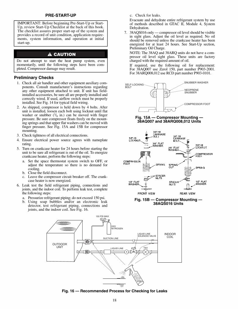
2. As shipped, compressor is held down by 4 bolts. Afterunit is installed, loosen each bolt using locknut until flatwasher or snubber (3/8 in.) can be moved with fingerpressure. Be sure compressor floats freely on the mount-ing springs and that upper flat washers can be moved withfinger pressure. See Fig. 15A and 15B for compressormounting.
3. Check tightness of all electrical connections.4. Ensure electrical power source agrees with nameplate
rating.5. Turn on crankcase heater for 24 hours before starting the
unit to be sure all refrigerant is out of the oil. To energizecrankcase heater, perform the following steps:a. Set the space thermostat system switch to OFF, or
adjust the temperature so there is no demand forcooling.
b. Close the field disconnect.c. Leave the compressor circuit breaker off. The crank-
case heater is now energized.6. Leak test the field refrigerant piping, connections and
joints, and the indoor coil. To perform leak test, completethe following steps:a. Pressurize refrigerant piping; do not exceed 150 psi.b. Using soap bubbles and/or an electronic leak
detector, test refrigerant piping, connections andjoints, and the indoor coil. See Fig. 16.
c. Check for leaks.Evacuate and dehydrate entire refrigerant system by useof methods described in GTAC II, Module 4, SystemDehydration.
7. 38AQS016 only — compressor oil level should be visiblein sight glass. Adjust the oil level as required. No oilshould be removed unless the crankcase heater has beenenergized for at least 24 hours. See Start-Up section,Preliminary Oil Charge.NOTE: The 38AQ and 38ARQ units do not have a com-pressor oil level sight glass. These units are factorycharged with the required amount of oil.If required, use the following oil for replacement:For 38AQ007 use Zerol 150, part number P903-2001.For 38ARQ008,012 use RCD part number P903-0101.
IMPORTANT: Before beginning Pre-Start-Up or Start-Up, review Start-Up Checklist at the back of this book.The checklist assures proper start-up of the system andprovides a record of unit condition, application require-ments, system information, and operation at initialstart-up.
Do not attempt to start the heat pump system, evenmomentarily, until the following steps have been com-pleted. Compressor damage may result.
Fig. 15B — Compressor Mounting —38AQS016 Units
SELF-LOCKINGBOLT
SNUBBER WASHER
NEOPRENESNUBBER
COMPRESSOR FOOT
Fig. 15A — Compressor Mounting —38AQ007 and 38ARQ008,012 Units
OUTDOORUNIT
INDOORCOIL
SOAP
TXV
SUCTION LINE
LIQUID LINE
DRYNITROGEN
150 PSI MAX
LIQUID LINESOLENOID VALVE
Fig. 16 — Recommended Process for Checking for Leaks

19
8. Backseat (open) compressor vapor and discharge valves.Now close valves one turn to allow refrigerant pressure toreach test gages.
Preliminary Charge
Before starting the unit, charge liquid refrigerant into thehigh side of the system through the liquid service valve. Allowhigh and low side pressures to equalize before starting com-pressor. If pressures do not equalize readily, charge vapor onlow side of system to assure charge in the evaporator. Refer toGTAC II, Module 5, Charging, Recovery, Recycling, and Rec-lamation for liquid charging procedures.Liquid Line Solenoid — To minimize refrigerant migra-tion to the compressor during the heat pump OFF cycle, the38AQ,ARQ unit must have a bi-flow liquid line solenoid valve(field supplied). The valve opens when the compressor is ener-gized, and closes when the compressor is deenergized. Thisreduces compressor flooded starts, thus significantly increasingcompressor life.Accumulator — The unit accumulator controls the rate ofliquid refrigerant to the compressor during heat pump operation.
The 38AQS accumulator features a unique method forreturning oil to the compressor. The oil return mechanism isexternal to the accumulator. The mixture of oil and refrigerantis metered to the compressor by a brass orifice which is remov-able and cleanable. The oil return mechanism also contains asolenoid valve that opens when the compressor is ON andcloses when the compressor is OFF. This keeps the liquidrefrigerant stored in the accumulator from draining to thecompressor during the heat pump OFF cycle, which furtherprotects the compressor against flooded starts.
START-UP
Compressor Rotation (38AQ,ARQ Units) — On3-phase units with scroll compressors, it is important to be cer-tain compressor is rotating in the proper direction. To determinewhether or not compressor is rotating in the proper direction:
1. Connect service gages to suction and discharge pressurefittings.
2. Energize the compressor.3. The vapor pressure should drop and the discharge pres-
sure should rise, as is normal on any start-up.If the vapor pressure does not drop and the discharge
pressure does not rise to normal levels:1. Note that the condenser fan is probably also rotating in
the wrong direction.
2. Turn off power to the unit, tag disconnect.3. Reverse any two of the unit power leads.4. Reapply power to the compressor, verify correct pressures.The vapor and discharge pressure levels should now move
to their normal start-up levels.
Compressor Overload — This overload interruptspower to the compressor when either the current or internalmotor winding temperature becomes excessive, and automati-cally resets when the internal temperature drops to a safe level.This overload usually resets within 60 minutes (or longer). Ifthe internal overload is suspected of being open, disconnect theelectrical power to the unit and check the circuit through theoverload with an ohmmeter or continuity tester.
Advanced Scroll Temperature Protection(ASTP) — Advanced Scroll Temperature Protection(ASTP) is a form of internal discharge temperature protectionthat unloads the scroll compressor when the internal tempera-ture reaches approximately 300 F. At this temperature, an inter-nal bi-metal disk valve opens and causes the scroll elements toseparate, which stops compression. Suction and discharge pres-sures balance while the motor continues to run. The longer thecompressor runs unloaded, the longer it must cool before thebi-metal disk resets. See Fig. 17.
To manually reset ASTP, the compressor should be stoppedand allowed to cool. If the compressor is not stopped, the motorwill run until the motor protector trips, which occurs up to90 minutes later. Advanced Scroll Temperature Protection willreset automatically before the motor protector resets, whichmay take up to 2 hours. A label located above the terminal boxidentifies Copeland Scroll compressor models (ZR94, 108 and125) that contain this technology. See Fig. 18.
The 38ARQ008 and 38ARQ012 units contain a 9 lb(4.1 kg) charge of refrigerant. Add remainder of prelimi-nary charge and allow pressure to equalize before startingcompressor. Failure to do so WILL cause the compressorto overheat in a few minutes, possibly causing permanentcompressor damage. The amount of refrigerant addedmust be at least 80% of the operating charge listed inthe Physical Data table (Tables 1A-1D).
Compressor crankcase heater must be on for 24 hoursbefore start-up. After the heater has been on for 24 hours,the unit can be started.
Prior to starting compressor, a preliminary charge of refrig-erant must be added to avoid possible compressor damage.
0
10
20
30
40
50
60
70
80
90
100
110
120
0 10 20 30 40 50 60 70 80 90
Compressor Unloaded Run Time (Minutes)
Rec
omm
ende
dC
oolin
gTim
e(M
i nut
es)
*Times are approximate. Various factors, including high humidity,high ambient temperature, and the presence of a sound blanketwill increase cool-down times.
Fig. 17 — Recommended Minimum Cool-DownTime After Compressor is Stopped*
Fig. 18 — Advanced Scroll TemperatureProtection Label

20
Compressor Lockout (CLO) Device — The Com-pressor lockout (CLO) device prevents the compressor fromstarting or running in a high pressure, loss-of-charge orfreezestat open situation. Reset the CLO device by setting thethermostat to eliminate cooling demand and return it to the orig-inal set point. If the system shuts down again for the same fault,determine the possible cause before attempting to reset the CLOdevice.
Preliminary Oil Charge (38AQS) — The compressoris factory charged with oil (see Tables 1A-1D). When oil ischecked at start-up, it may be necessary to add or remove oilto bring it to the proper level. Add oil only if necessary tobring oil into view in sight glass. Use only Carrier-approvedcompressor oil. One recommended oil level adjustmentmethod is as follows:ADD OIL — Close vapor service valve and pump downcrankcase to 2 psig. Wait a few minutes and repeat until pres-sure remains steady at 2 psig. Remove oil fill plug above thesight glass, add oil through plug hole, and replace plug. Runcompressor for 20 minutes and check oil level.NOTE: Use only Carrier approved compressor oil. Approvedsources are:Petroleum Specialties, Inc.. . . . . . . . . . . . . . . . . . . . Cryol 150ATexaco, Inc.. . . . . . . . . . . . . . . . . . . . . . . . . . . . . . Capella WF32Witco Chemical Co.. . . . . . . . . . . . . . . . . . . . . . . . . Suniso 3GS
Do not use oil that has been drained out, or oil that has beenexposed to atmosphere.REMOVE OIL — Pump down compressor to 2 psig. Loosenthe 1/4-in. pipe plug at the compressor base and allow the oil toseep out past the threads of the plug. Retighten plug when levelis correct.NOTE: The crankcase is slightly pressurized. Do not removethe plug, or the entire oil charge will be lost.
Small amounts of oil can be removed through the oil pumpdischarge connection while the compressor is running.
Start Unit — The field disconnect is closed, the fan circuitbreaker is closed, and the space thermostat is set above ambientso that there is no demand for cooling. Only the crankcaseheater will be energized.
Next, close the compressor circuit breaker and then resetspace thermostat below ambient so that a call for cooling isensured.NOTE: Do not use circuit breaker to start and stop the com-pressor except in an emergency.
After starting, there is a delay of at least 3 seconds beforecompressor starts.
Adjust Refrigerant Charge — Refer to Charging ChartsFig. 19A-19C and Table 8. Do not exceed maximum refriger-ant charge. Vary refrigerant until the conditions of the chart aremet. Note that charging charts are different from type normallyused. Charts are based on charging the units to the correctsubcooling for the various operating conditions. Accurate pres-sure gage and temperature sensing device are required.
Connect the pressure gage to the service port on the liquidline service valve. Mount the temperature sensing device onthe liquid line, close to the liquid line service valve and insulateit so that outdoor ambient temperature does not affect the read-ing. Indoor airflow must be within the normal operating rangeof the unit. Operate unit a minimum of 15 minutes. Ensurepressure and temperature readings have stabilized. Plot liquidpressure and temperature on chart and add or reduce charge tomeet curve. Adjust charge to conform with charging chart,using the liquid pressure and temperature to read chart.
If the sight glass is cloudy, check refrigerant charge again.Ensure all fans are operating. Also ensure maximum allowableliquid lift has not been exceeded. If charged per chart and if thesight glass is still cloudy, check for a plugged filter drier or apartially closed solenoid valve. Replace or repair, as needed.
Fig. 19B — 38ARQ008,012 Charging Chart
Fig. 19A — 38AQ007 Charging Chart
Fig. 19C — 38AQS016 Charging Chart
50
LIQUID PRESSURE AT LIQUID VALVE (PSIG)
LIQ
UID
TE
MP
ER
AT
UR
EA
TLI
QU
IDV
ALV
E(F
)
344LIQUID PRESSURE AT LIQUID VALVE (Kilopascals)
ADD CHARGE IF ABOVE CURVE
REDUCE CHARGE IF BELOW CURVE
50
60
70
80
90
100
110
120
130
140
100 150 200 250 300 350 400
689 1034 1379 1724 2069 2414
LIQ
UID
TE
MP
ER
AT
UR
EA
TLI
QU
IDV
ALV
E(C
)
10
16
21
27
32
38
43
49
54
60

21
Checking Heating Cycle Operation — Place ther-mostat selector switch at HEAT and reset the space setpoint above ambient temperature so that a call for heating isensured. Compressor will start within 5 minutes. Observesystem operation.
Check Compressor Oil Level (38AQS) — After ad-justing the refrigerant charge, allow the system to run fullyloaded for 20 minutes. Running oil level should be within viewin the crankcase sight glass. Stop compressor at the field powersupply disconnect and check the crankcase oil level. Add oilonly if necessary to bring the oil into view in the sight glass. Ifoil is added, run the system for an additional 10 minutes, thenstop and check oil level. If the level remains low, check thepiping system for proper design for oil return; also check thesystem for leaks.
If the initial check shows too much oil (too high in the sightglass) remove oil to proper level. See Preliminary Oil Chargesection for proper procedure for adding and removing oil.
When the above checks are complete, repeat the procedurewith the unit operating at minimum load conditions. Unloadthe compressor by disconnecting the field-control circuit leadat TB2 .
Reconnect the field-control circuit lead when checks arecomplete.
Final Checks — Ensure all safety controls are operating,control panel covers are on, and the service panels are in place.
Table 8 — Maximum Refrigerant Charge
SEQUENCE OF OPERATION
38AQ007 Units — When power is supplied to unit, thetransformer (TRAN) and crankcase heater (CCH) are energized.COOLING — On a call for cooling, the thermostat completesthe following circuits: R-G, R-Y, and R-O. If the compressorrecycle delay of 3 minutes is complete, the compressor andoutdoor fan start. The reversing valve is energized for coolingand the indoor-fan motor starts.
When the thermostat is satisfied, the circuits are opened,and the compressor, outdoor-fan motor, and indoor-fan motorstop. The reversing valve is deenergized.HEATING — On a call for heating, the thermostat completesthe following circuits: R-G and R-Y. If the compressor recycledelay of 3 minutes is complete, the compressor and outdoorfan start. The indoor-fan motor will also start.
If room temperature continues to fall, the thermostatcompletes circuit R-W. If the optional electric heat package isused, the heat relay is energized, and the electric heaters areenergized.
When the thermostat is satisfied, the circuits are opened,and the compressor, outdoor-fan motor, heaters, and indoor-fanmotor stop.DEFROST — Defrost board (DB) is a time and temperaturecontrol, which includes a field-selectable time period betweenchecks for frost (30, 50, and 90 minutes). Electronic timer anddefrost cycle start only when contactor is energized and defrostthermostat (DFT) is closed (below 28 F [–2.2 C]).
Defrost mode is identical to Cooling mode, except outdoor-fan motor (OFM) stops and a bank of supplemental electricheat turns on to warm air supplying the conditioned space.Defrost mode is terminated when the DFT reaches 65 F(18.3 C).AIR CIRCULATION — When the fan switch is at FAN ON,the indoor-air fans operate continuously to provide ventilation.The thermostat operates the other components as describedabove.EMERGENCY HEAT CYCLE — If the compressor is inoper-ative due to a tripped safety device, the second stage of thethermostat automatically energizes the indoor-air fan and theelectric resistance heaters (if equipped).
38ARQ008,012 Units — When power is supplied tounit, the transformer (TRAN) is energized. The crankcaseheater is also energized.COOLING — With the thermostat subbase in the coolingposition, and when the space temperature comes within 2° F(1° C) of the cooling set point, the thermostat makes circuitR-O. This energizes the reversing valve solenoid (RVS) andplaces the unit in standby condition for cooling.
As the space temperature continues to rise, the second stageof the thermostat makes, closing circuit R-Y. When compressortime delay (5 ± 2 minutes) is completed, a circuit is made tocontactor (C), starting the compressor (COMP) and outdoor-fan motor (OFM). Circuit R-G is made at the same time,energizing the indoor-fan contactor (IFC) and starting theindoor-fan motor (IFM) after one-second delay.
When the thermostat is satisfied, contacts open, deenergiz-ing C. The COMP, IFM, and OFM stop.HEATING — On a call for heat, thermostat makes circuitsR-Y and R-G. When compressor time delay (5 ± 2 minutes) iscompleted, a circuit is made to C, starting COMP and OFM.Circuit R-G also energizes IFC and starts IFM after a 1-seconddelay.
38AQS016 UnitsHEATING — Place thermostat selector at HEAT and set tem-perature selector above room ambient.COOLING — Place thermostat selector at COOL and set tem-perature selector below room ambient.
When thermostat calls for unit operation (either heating orcooling), the indoor-fan motor starts immediately. Theoutdoor-fan motors and compressor start within 3 seconds to5 minutes depending on when unit was last shut off by thermo-stat, because unit contains a compressor time delay circuit.When first-stage cooling is required, thermostat (TC1) closes,causing the heat pump to start with an unloaded compressor.When TC2 closes, demanding additional cooling, the compres-sor loads to full load operation.
During heating, compressor is always fully loaded. WhenTH1 demands first-stage heating, the heat pump starts within3 seconds to 5 minutes depending on when unit was last shutoff by thermostat, because unit contains a compressor timedelay circuit. (The defrost board has speed terminals to shortenthis cycle.) When TH2 of the thermostat closes, auxiliary heatsupply (electric strip heat) is energized in 1 or 2 stages depend-ing on number of stages available and whether outdoor thermo-stats are closed.
Never charge liquid into the low-pressure side of system.Do not overcharge. During charging or removal of refriger-ant, be sure indoor-fan system is operating.
Charge unit on cooling cycle only. If unit is charged onheating cycle, overcharging may occur.
UNIT 38R-22
(lb) (kg)AQ007 27.0 12.2
ARQ008,012 34.234.2
15.515.5
AQS016 62.0 28.1
Y2
22
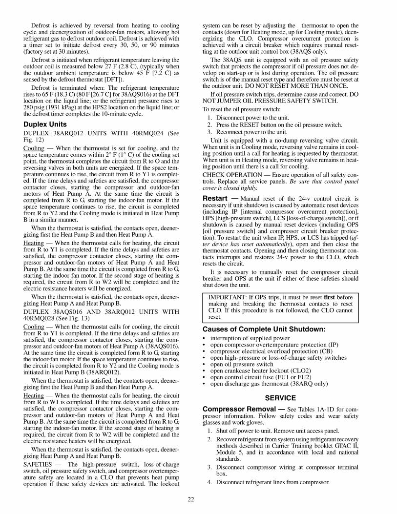
Defrost is achieved by reversal from heating to coolingcycle and deenergization of outdoor-fan motors, allowing hotrefrigerant gas to defrost outdoor coil. Defrost is achieved witha timer set to initiate defrost every 30, 50, or 90 minutes(factory set at 30 minutes).
Defrost is initiated when refrigerant temperature leaving theoutdoor coil is measured below 27 F (2.8 C), (typically whenthe outdoor ambient temperature is below 45 F [7.2 C] assensed by the defrost thermostat [DFT]).
Defrost is terminated when: The refrigerant temperaturerises to 65 F (18.3 C) (80 F [26.7 C] for 38AQS016) at the DFTlocation on the liquid line; or the refrigerant pressure rises to280 psig (1931 kPag) at the HPS2 location on the liquid line; orthe defrost timer completes the 10-minute cycle.
Duplex UnitsDUPLEX 38ARQ012 UNITS WITH 40RMQ024 (SeeFig. 12)Cooling — When the thermostat is set for cooling, and thespace temperature comes within 2° F (1° C) of the cooling setpoint, the thermostat completes the circuit from R to O and thereversing valves in both units are energized. If the space tem-perature continues to rise, the circuit from R to Y1 is complet-ed. If the time delays and safeties are satisfied, the compressorcontactor closes, starting the compressor and outdoor-fanmotors of Heat Pump A. At the same time the circuit iscompleted from R to G, starting the indoor-fan motor. If thespace temperature continues to rise, the circuit is completedfrom R to Y2 and the Cooling mode is initiated in Heat PumpB in a similar manner.
When the thermostat is satisfied, the contacts open, deener-gizing first the Heat Pump B and then Heat Pump A.Heating — When the thermostat calls for heating, the circuitfrom R to Y1 is completed. If the time delays and safeties aresatisfied, the compressor contactor closes, starting the com-pressor and outdoor-fan motors of Heat Pump A and HeatPump B. At the same time the circuit is completed from R to G,starting the indoor-fan motor. If the second stage of heating isrequired, the circuit from R to W2 will be completed and theelectric resistance heaters will be energized.
When the thermostat is satisfied, the contacts open, deener-gizing Heat Pump A and Heat Pump B.DUPLEX 38AQS016 AND 38ARQ012 UNITS WITH40RMQ028 (See Fig. 13)Cooling — When the thermostat calls for cooling, the circuitfrom R to Y1 is completed. If the time delays and safeties aresatisfied, the compressor contactor closes, starting the com-pressor and outdoor-fan motors of Heat Pump A (38AQS016).At the same time the circuit is completed form R to G, startingthe indoor-fan motor. If the space temperature continues to rise,the circuit is completed from R to Y2 and the Cooling mode isinitiated in Heat Pump B (38ARQ012).
When the thermostat is satisfied, the contacts open, deener-gizing first the Heat Pump B and then Heat Pump A.Heating — When the thermostat calls for heating, the circuitfrom R to W1 is completed. If the time delays and safeties aresatisfied, the compressor contactor closes, starting the com-pressor and outdoor-fan motors of Heat Pump A and HeatPump B. At the same time the circuit is completed from R to G,starting the indoor-fan motor. If the second stage of heating isrequired, the circuit from R to W2 will be completed and theelectric resistance heaters will be energized.
When the thermostat is satisfied, the contacts open, deener-gizing Heat Pump A and Heat Pump B.SAFETIES — The high-pressure switch, loss-of-chargeswitch, oil pressure safety switch, and compressor overtemper-ature safety are located in a CLO that prevents heat pumpoperation if these safety devices are activated. The lockout
system can be reset by adjusting the thermostat to open thecontacts (down for Heating mode, up for Cooling mode), deen-ergizing the CLO. Compressor overcurrent protection isachieved with a circuit breaker which requires manual reset-ting at the outdoor unit control box (38AQS only).
The 38AQS unit is equipped with an oil pressure safetyswitch that protects the compressor if oil pressure does not de-velop on start-up or is lost during operation. The oil pressureswitch is of the manual reset type and therefore must be reset atthe outdoor unit. DO NOT RESET MORE THAN ONCE.
If oil pressure switch trips, determine cause and correct. DONOT JUMPER OIL PRESSURE SAFETY SWITCH.To reset the oil pressure switch:
1. Disconnect power to the unit.2. Press the RESET button on the oil pressure switch.3. Reconnect power to the unit.Unit is equipped with a no-dump reversing valve circuit.
When unit is in Cooling mode, reversing valve remains in cool-ing position until a call for heating is requested by thermostat.When unit is in Heating mode, reversing valve remains in heat-ing position until there is a call for cooling.CHECK OPERATION — Ensure operation of all safety con-trols. Replace all service panels. Be sure that control panelcover is closed tightly.
Restart — Manual reset of the 24-v control circuit isnecessary if unit shutdown is caused by automatic reset devices(including IP [internal compressor overcurrent protection],HPS [high-pressure switch], LCS [loss-of-charge switch]), or ifshutdown is caused by manual reset devices (including OPS[oil pressure switch] and compressor circuit breaker protec-tion). To restart the unit when IP, HPS, or LCS has tripped (af-ter device has reset automatically), open and then close thethermostat contacts. Opening and then closing thermostat con-tacts interrupts and restores 24-v power to the CLO, whichresets the circuit.
It is necessary to manually reset the compressor circuitbreaker and OPS at the unit if either of these safeties shouldshut down the unit.
Causes of Complete Unit Shutdown:• interruption of supplied power• open compressor overtemperature protection (IP)• compressor electrical overload protection (CB)• open high-pressure or loss-of-charge safety switches• open oil pressure switch• open crankcase heater lockout (CLO2)• open control circuit fuse (FU1 or FU2)• open discharge gas thermostat (38ARQ only)
SERVICE
Compressor Removal — See Tables 1A-1D for com-pressor information. Follow safety codes and wear safetyglasses and work gloves.
1. Shut off power to unit. Remove unit access panel.2. Recover refrigerant from system using refrigerant recovery
methods described in Carrier Training booklet GTAC II,Module 5, and in accordance with local and nationalstandards.
3. Disconnect compressor wiring at compressor terminalbox.
4. Disconnect refrigerant lines from compressor.
IMPORTANT: If OPS trips, it must be reset first beforemaking and breaking the thermostat contacts to resetCLO. If this procedure is not followed, the CLO cannotreset.
23
5. Remove screws from compressor mounting plate.
6. Remove or disconnect crankcase heater from compressorbase.
7. Remove compressor from unit.8. On 38AQS016 unit remove compressor holddown bolts
and lift compressor off mounting plate.9. Clean system. Add new liquid line filter drier.
10. Install new compressor on compressor mounting plateand position in unit. Connect vapor and discharge lines tocompressor. Secure mounting plate with compressor tounit. Ensure that compressor holddown bolts are in place.Connect wiring. Install crankcase heater.
11. Evacuate and recharge unit.12. Restore unit power.
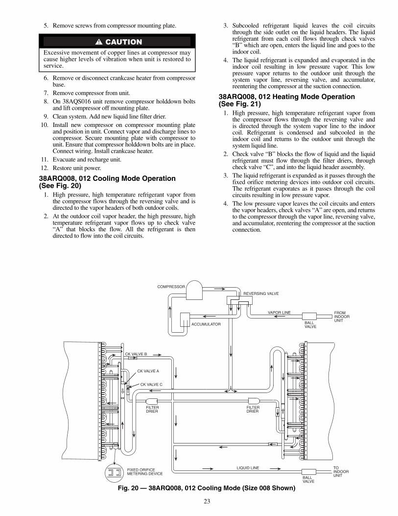
38ARQ008, 012 Cooling Mode Operation(See Fig. 20)
1. High pressure, high temperature refrigerant vapor fromthe compressor flows through the reversing valve and isdirected to the vapor headers of both outdoor coils.
2. At the outdoor coil vapor header, the high pressure, hightemperature refrigerant vapor flows up to check valve“A” that blocks the flow. All the refrigerant is thendirected to flow into the coil circuits.
3. Subcooled refrigerant liquid leaves the coil circuitsthrough the side outlet on the liquid headers. The liquidrefrigerant from each coil flows through check valves“B” which are open, enters the liquid line and goes to theindoor coil.
4. The liquid refrigerant is expanded and evaporated in theindoor coil resulting in low pressure vapor. This lowpressure vapor returns to the outdoor unit through thesystem vapor line, reversing valve, and accumulator,reentering the compressor at the suction connection.
38ARQ008, 012 Heating Mode Operation(See Fig. 21)
1. High pressure, high temperature refrigerant vapor fromthe compressor flows through the reversing valve andis directed through the system vapor line to the indoorcoil. Refrigerant is condensed and subcooled in theindoor coil and returns to the outdoor unit through thesystem liquid line.
2. Check valve “B” blocks the flow of liquid and the liquidrefrigerant must flow through the filter driers, throughcheck valve “C”, and into the liquid header assembly.
3. The liquid refrigerant is expanded as it passes through thefixed orifice metering devices into outdoor coil circuits.The refrigerant evaporates as it passes through the coilcircuits resulting in low pressure vapor.
4. The low pressure vapor leaves the coil circuits and entersthe vapor headers, check valves “A” are open, and returnsto the compressor through the vapor line, reversing valve,and accumulator, reentering the compressor at the suctionconnection.
Excessive movement of copper lines at compressor maycause higher levels of vibration when unit is restored toservice.
ACCUMULATOR
COMPRESSOR
REVERSING VALVE
VAPOR LINE
BALLVALVE
FROMINDOORUNIT
FILTERDRIER
LIQUID LINE
BALLVALVE
TOINDOORUNIT
FIXED ORIFICEMETERING DEVICE
FILTERDRIER
CK VALVE C
CK VALVE A
CK VALVE B
Fig. 20 — 38ARQ008, 012 Cooling Mode (Size 008 Shown)

24
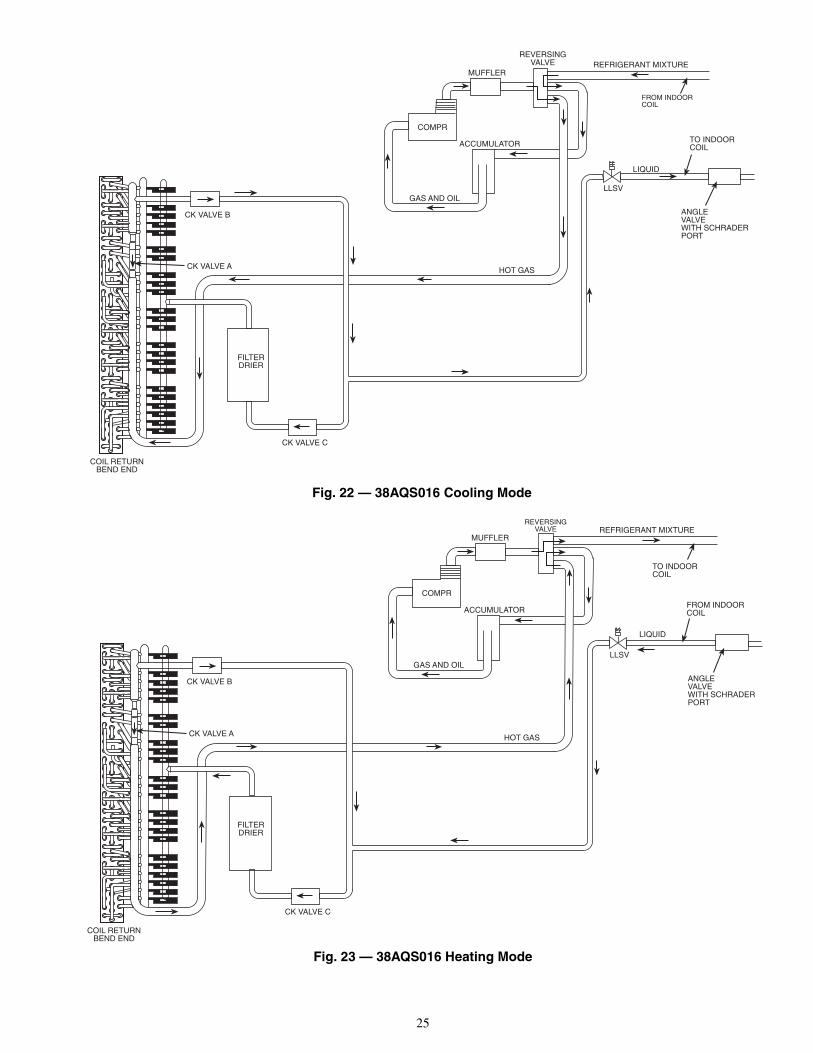
38AQS016 Cooling Mode Operation(See Fig. 22)
1. High pressure, high temperature refrigerant vapor fromthe compressor flows through the reversing valve and isdirected to the outdoor coil vapor header.
2. At the outdoor coil vapor header, the high pressure, hightemperature refrigerant vapor flows up to check valve“A” that blocks the flow. All the refrigerant is thendirected to flow into the coil circuits.
3. Subcooled refrigerant liquid leaves the coil circuitsentering the portion of the vapor header which is abovecheck valve “A”. Check valve “C” is closed, therefore,the liquid refrigerant passes through check valve “B,”which is open, and enters the liquid line and goes to theindoor coil.
4. The liquid refrigerant is expanded and evaporated in theindoor coil resulting in low pressure vapor. This lowpressure vapor returns to the outdoor unit through thesystem vapor line, reversing valve, and accumulator,reentering the compressor at the suction connection.
38AQS016 Heating Mode Operation(See Fig. 23)
1. High pressure, high temperature refrigerant vapor fromthe compressor flows through the reversing valve andis directed through the system vapor line to the indoorcoil. Refrigerant is condensed and subcooled in theindoor coil and returns to the outdoor unit through thesystem liquid line.
2. Check valve “B” blocks the flow of liquid and the refrig-erant is then directed to flow through check valve “C”(which is open), through the filter drier, and into theliquid header assembly.
3. The liquid refrigerant is expanded as it passes through thecapillary tubes into outdoor coil circuits. The refrigerantevaporates as it passes through the coil circuits resultingin low pressure vapor.
4. The low pressure vapor leaves the coil circuits and entersthe vapor header, check valve “A” is open, and returns tothe compressor through the vapor line, reversing valve,and accumulator, reentering the compressor at the suctionconnection.
Crankcase Heater — The crankcase heater preventsrefrigerant migration and compressor oil dilution duringshutdown when compressor is not operating.
Close both compressor service valves when crankcaseheater is deenergized for more than 6 hours.
Outdoor Unit Fans — Each fan is supported by aformed-wire mount bolted to the fan deck and covered with awire guard. On the 38AQS016, the exposed end of the motorshaft is covered with a rubber boot. In case a fan motor must berepaired or replaced, be sure the rubber boot is put back onwhen the fan is reinstalled and be sure the fan guard is in placebefore starting the unit.
Lubrication — Fan motors have permanently sealedbearings. No further lubrication is required.
ACCUMULATOR
COMPRESSOR
REVERSING VALVE
VAPOR LINE
BALLVALVE
TOINDOORUNIT
FILTERDRIER
LIQUID LINE
BALLVALVE
FROMINDOORUNIT
FIXED ORIFICEMETERING DEVICE
FILTERDRIER
CK VALVE C
CK VALVE A
CK VALVE B
Fig. 21 — 38ARQ008, 012 Heating Mode (Size 008 Shown)
25
FILTERDRIER
COMPR
CK VALVE B
CK VALVE A
CK VALVE C
LLSV
LIQUID
HOT GAS
GAS AND OIL
MUFFLER
ACCUMULATOR
REVERSINGVALVE REFRIGERANT MIXTURE
FROM INDOORCOIL
TO INDOORCOIL
ANGLEVALVEWITH SCHRADERPORT
COIL RETURNBEND END
Fig. 23 — 38AQS016 Heating Mode
FILTERDRIER
COMPR
CK VALVE B
CK VALVE A
CK VALVE C
LLSV
LIQUID
HOT GAS
GAS AND OIL
MUFFLER
ACCUMULATOR
REVERSINGVALVE REFRIGERANT MIXTURE
FROM INDOORCOIL
TO INDOORCOIL
ANGLEVALVEWITH SCHRADERPORT
COIL RETURNBEND END
Fig. 22 — 38AQS016 Cooling Mode
26
Coil Cleaning and Maintenance — This section dis-cusses the cleaning and the maintenance of standard coils andE-Coated coils. Routine cleaning of coil surfaces is essential tominimize contamination build-up and remove harmful residue.Inspect coils monthly and clean as required.CLEANING STANDARD COILS — Standard coils can becleaned with a vacuum cleaner, washed out with low velocitywater, blown out with compressed air, or brushed (do not usewire brush). Fan motors are dripproof but not waterproof. Donot use acid cleaners.
Clean coil annually or as required by location or outdoor airconditions. Inspect coil monthly and clean as required. Fins arenot continuous through coil sections. Dirt and debris may passthrough first section and become trapped, restricting condenserairflow. Use a flashlight to determine if dirt or debris hascollected between coil sections.
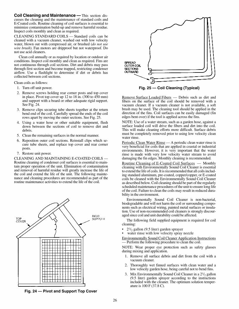
Clean coils as follows:1. Turn off unit power.2. Remove screws holding rear corner posts and top cover
in place. Pivot top cover up 12 to 18 in. (300 to 450 mm)and support with a board or other adequate rigid support.See Fig. 24.
3. Remove clips securing tube sheets together at the returnbend end of the coil. Carefully spread the ends of the coilrows apart by moving the outer sections. See Fig. 25.
4. Using a water hose or other suitable equipment, flushdown between the sections of coil to remove dirt anddebris.
5. Clean the remaining surfaces in the normal manner.6. Reposition outer coil sections. Reinstall clips which se-
cure tube sheets, and replace top cover and rear cornerposts.
7. Restore unit power.CLEANING AND MAINTAINING E-COATED COILS —Routine cleaning of condenser coil surfaces is essential to main-tain proper operation of the unit. Elimination of contaminationand removal of harmful residue will greatly increase the life ofthe coil and extend the life of the unit. The following mainte-nance and cleaning procedures are recommended as part of theroutine maintenance activities to extend the life of the coil.
Remove Surface Loaded Fibers — Debris such as dirt andfibers on the surface of the coil should be removed with avacuum cleaner. If a vacuum cleaner is not available, a softbrush may be used. The cleaning tool should be applied in thedirection of the fins. Coil surfaces can be easily damaged (finedges bent over) if the tool is applied across the fins.NOTE: Use of a water stream, such as a garden hose, against asurface loaded coil will drive the fibers and dirt into the coil.This will make cleaning efforts more difficult. Surface debrismust be completely removed prior to using low velocity cleanwater rinse.Periodic Clean Water Rinse — A periodic clean water rinse isvery beneficial for coils that are applied in coastal or industrialenvironments. However, it is very important that the waterrinse is made with very low velocity water stream to avoiddamaging the fin edges. Monthly cleaning is recommended.Routine Cleaning of E-Coated Coil Surfaces — Monthlycleaning with Environmentally Sound Coil Cleaner is essentialto extend the life of coils. It is recommended that all coils includ-ing standard aluminum, pre-coated, copper/copper, or E-coatedcoils be cleaned with the Environmentally Sound Coil Cleaneras described below. Coil cleaning should be part of the regularlyscheduled maintenance procedures of the unit to ensure long lifeof the coil. Failure to clean the coils may result in reduced dura-bility in the environment.
Environmentally Sound Coil Cleaner is non-bacterial,biodegradable and will not harm the coil or surrounding compo-nents such as electrical wiring, painted metal surfaces or insula-tion. Use of non-recommended coil cleaners is strongly discour-aged since coil and unit durability could be affected.
The following field supplied equipment is required for coilcleaning:• 21/2 gallon (9.5 liter) garden sprayer• water rinse with low velocity spray nozzleEnvironmentally Sound Coil Cleaner Application Instructions— Perform the following procedure to clean the coil.NOTE: Wear proper eye protection such as safety glassesduring mixing and application.
1. Remove all surface debris and dirt from the coil with avacuum cleaner.
2. Thoroughly wet finned surfaces with clean water and alow velocity garden hose, being careful not to bend fins.
3. Mix Environmentally Sound Coil Cleaner in a 21/2 gallon(9.5 liter) garden sprayer according to the instructionsincluded with the cleaner. The optimum solution temper-ature is 100 F (37.8 C).
Fig. 25 — Coil Cleaning (Typical)
Fig. 24 — Pivot and Support Top Cover
27
4. Thoroughly apply Environmentally Sound Coil Cleanersolution to all coil surfaces including finned area, tubesheets, and coil headers. Hold garden sprayer nozzleclose to finned areas and apply cleaner with a vertical,up-and-down motion. Avoid spraying in horizontalpattern to minimize potential for fin damage. Ensurecleaner thoroughly penetrates deep into finned areas.Interior and exterior finned areas must be thoroughlycleaned.
5. Allow finned surfaces to remain wet with cleaning solu-tion for 10 minutes. Ensure surfaces are not allowed todry before rinsing. Reapply cleaner as needed to ensure10-minute saturation is achieved.
6. Thoroughly rinse all surfaces with low velocity cleanwater using downward rinsing motion of water spraynozzle. Protect fins from damage from the spray nozzle.
DO NOT USE water in excess of 130 F (54.4 C).Enzymes in coil cleaner will be destroyed and coil cleanerwill not be effective.
Do not use bleach, harsh chemicals, or acid cleaners on out-door or indoor coils of any kind. These types of cleaners aredifficult to rinse, and they promote rapid corrosion of the fincollar — copper tube connection. Only use the Environ-mentally Sound Coil Cleaner.Never use high pressure air or liquids to clean coils. Highpressures damage coils and increase the airside pressuredrop. To promote unit integrity, follow cleaning and main-tenance procedures in this document.
28
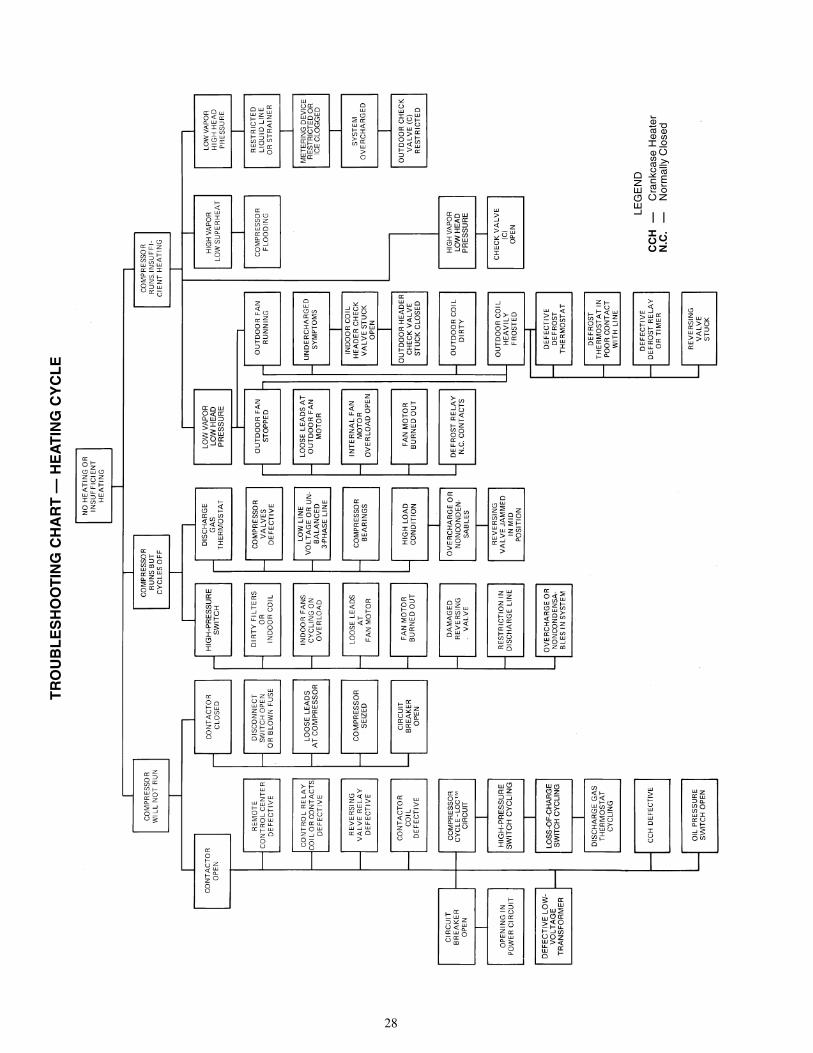
TR
OU
BL
ES
HO
OT
ING
CH
AR
T—
HE
AT
ING
CY
CL
E
LEG
EN
DC
CH
—C
rank
case
Hea
ter
N.C
.—
Nor
mal
lyC
lose
d

29
TR
OU
BL
ES
HO
OT
ING
CH
AR
T—
CO
OL
ING
CY
CL
E
LEG
EN
DC
CH
—C
rank
case
Hea
ter
TX
V—
The
rmos
tatic
Exp
ansi
onV
alve

Manufacturer reserves the right to discontinue, or change at any time, specifications or designs without notice and without incurring obligations.PC 111 Catalog No. 533-80118 Printed in U.S.A. 38A-19SI Pg 30 9-04 Replaces: 38A-16SIBook 1 4
Tab 5a 5a
Copyright 2004 Carrier Corporation

CL-1
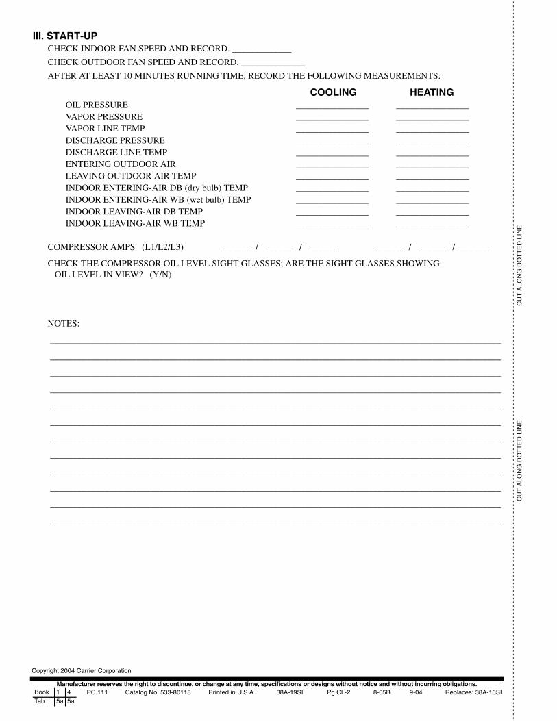
START-UP CHECKLIST
I. PRELIMINARY INFORMATIONOUTDOOR UNIT: MODEL NO. ___________________________ SERIAL NO.: _______________________________
INDOOR UNIT: MODEL NO. _____________________________ SERIAL NO.: _______________________________
ADDITIONAL ACCESSORIES __________________________________________________________________________
II. PRE-START-UP
OUTDOOR UNITIS THERE ANY SHIPPING DAMAGE? (Y/N)__________
IF SO, WHERE:___________________________________________________________________________________________________________________________________________________________________________________________
WILL THIS DAMAGE PREVENT UNIT START-UP? (Y/N) __________
CHECK POWER SUPPLY. DOES IT AGREE WITH UNIT? (Y/N) ___________
HAS THE GROUND WIRE BEEN CONNECTED? (Y/N)___________
HAS THE CIRCUIT PROTECTION BEEN SIZED AND INSTALLED PROPERLY? (Y/N)__________
ARE THE POWER WIRES TO THE UNIT SIZED AND INSTALLED PROPERLY? (Y/N)__________
HAVE COMPRESSOR HOLDDOWN BOLTS BEEN LOOSENED (Snubber washers are snug, but not tight)?(Y/N) _____________
CONTROLSARE THERMOSTAT AND INDOOR FAN CONTROL WIRING
CONNECTIONS MADE AND CHECKED? (Y/N) ____________
ARE ALL WIRING TERMINALS (including main power supply) TIGHT? (Y/N) _____________
HAS CRANKCASE HEATER BEEN ENERGIZED FOR 24 HOURS? (Y/N) _____________
INDOOR UNITHAS WATER BEEN PLACED IN DRAIN PAN TO CONFIRM PROPER DRAINAGE? (Y/N) ___________
ARE PROPER AIR FILTERS IN PLACE? (Y/N) ____________
HAVE FAN AND MOTOR PULLEYS BEEN CHECKED FOR PROPER ALIGNMENT? (Y/N) ___________
DO THE FAN BELTS HAVE PROPER TENSION? (Y/N) _______________
HAS CORRECT FAN ROTATION BEEN CONFIRMED? (Y/N)______________
PIPINGHAVE LEAK CHECKS BEEN MADE AT COMPRESSOR, OUTDOOR UNIT, INDOOR UNIT,
TXVs (Thermostatic Expansion Valves), SOLENOID VALVES, FILTER DRIERS, AND FUSIBLEPLUGS WITH A LEAK DETECTOR? (Y/N)______________
LOCATE, REPAIR, AND REPORT ANY LEAKS. ___________________________________________________________
HAVE ALL COMPRESSOR SERVICE VALVES BEEN FULLY OPENED (BACKSEATED)? (Y/N) ________
HAS LIQUID LINE SERVICE VALVE BEEN OPENED? (Y/N) __________
IS THE OIL LEVEL IN COMPRESSOR CRANKCASE VISIBLE IN THE COMPRESSOR SIGHT GLASS?(Y/N) _____________
CHECK VOLTAGE IMBALANCELINE-TO-LINE VOLTS: AB _________V AC _________ V BC _________ V
(AB + AC + BC)/3 = AVERAGE VOLTAGE = ____________ V
MAXIMUM DEVIATION FROM AVERAGE VOLTAGE = ___________ V
VOLTAGE IMBALANCE = 100 X (MAX DEVIATION)/(AVERAGE VOLTAGE) = ____________%
IF OVER 2% VOLTAGE IMBALANCE, DO NOT ATTEMPT TO START SYSTEM!CALL LOCAL POWER COMPANY FOR ASSISTANCE.
Manufacturer reserves the right to discontinue, or change at any time, specifications or designs without notice and without incurring obligations.PC 111 Catalog No. 533-80118 Printed in U.S.A. 38A-19SI Pg CL-2 8-05B 9-04 Replaces: 38A-16SIBook 1 4
Tab 5a 5a
Copyright 2004 Carrier Corporation
--
--
--
--
--
--
--
--
--
--
--
--
--
--
--
--
--
--
--
--
--
--
--
--
--
--
--
--
--
--
--
--
--
--
--
--
--
--
--
--
--
--
--
--
--
--
--
--
--
--
--
--
--
--
--
--
--
--
--
--
--
--
--
--
--
--
--
--
--
--
--
--
--
--
--
--
--
--
--
--
--
--
--
--
--
--
---
--
--
--
--
--
--
--
--
--
-C
UT
ALO
NG
DO
TT
ED
LIN
EC
UT
ALO
NG
DO
TT
ED
LIN
E
III. START-UPCHECK INDOOR FAN SPEED AND RECORD. _____________
CHECK OUTDOOR FAN SPEED AND RECORD. ______________
AFTER AT LEAST 10 MINUTES RUNNING TIME, RECORD THE FOLLOWING MEASUREMENTS:
COOLING HEATINGOIL PRESSURE ________________ ________________VAPOR PRESSURE ________________ ________________VAPOR LINE TEMP ________________ ________________DISCHARGE PRESSURE ________________ ________________DISCHARGE LINE TEMP ________________ ________________ENTERING OUTDOOR AIR ________________ ________________LEAVING OUTDOOR AIR TEMP ________________ ________________INDOOR ENTERING-AIR DB (dry bulb) TEMP ________________ ________________INDOOR ENTERING-AIR WB (wet bulb) TEMP ________________ ________________INDOOR LEAVING-AIR DB TEMP ________________ ________________INDOOR LEAVING-AIR WB TEMP ________________ ________________
COMPRESSOR AMPS (L1/L2/L3) ______ / ______ / ______ ______ / ______ / _______
CHECK THE COMPRESSOR OIL LEVEL SIGHT GLASSES; ARE THE SIGHT GLASSES SHOWINGOIL LEVEL IN VIEW? (Y/N)
NOTES:
___________________________________________________________________________________________________
___________________________________________________________________________________________________
___________________________________________________________________________________________________
___________________________________________________________________________________________________
___________________________________________________________________________________________________
___________________________________________________________________________________________________
___________________________________________________________________________________________________
___________________________________________________________________________________________________
___________________________________________________________________________________________________
___________________________________________________________________________________________________
___________________________________________________________________________________________________
___________________________________________________________________________________________________