gek 116403 ge file. performance tests
DESCRIPTION
GE DOCUMENT- G.e equipment fileTRANSCRIPT

gGEK 116403
June 2009
GE Energy
These instructions do not purport to cover all details or variations in equipment nor to provide for every possible contingency to be met in connection with installation, operation or maintenance. Should further information be desired or should particular problems arise which are not covered sufficiently for the purchaser's purposes the matter should be referred to the GE Company.
© General Electric Company, 2009. GE Proprietary Information. All Rights Reserved.
Estimating Gas Turbine Performance
GEK 116403 Estimating Gas Turbine Performance
2 © General Electric Company, 2009. GE Proprietary Information. All Rights Reserved.
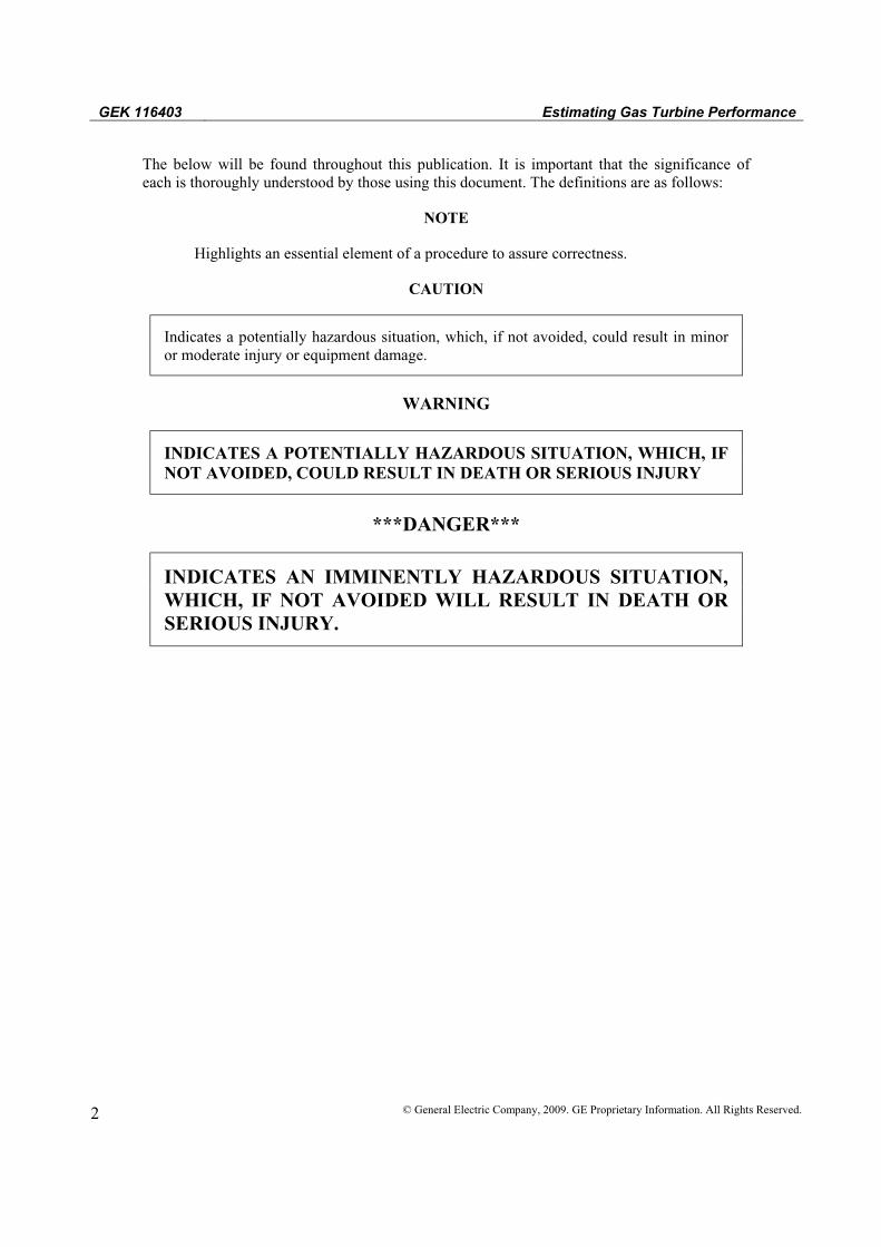
The below will be found throughout this publication. It is important that the significance of each is thoroughly understood by those using this document. The definitions are as follows:
NOTE
Highlights an essential element of a procedure to assure correctness.
CAUTION
Indicates a potentially hazardous situation, which, if not avoided, could result in minor or moderate injury or equipment damage.
WARNING
INDICATES A POTENTIALLY HAZARDOUS SITUATION, WHICH, IF NOT AVOIDED, COULD RESULT IN DEATH OR SERIOUS INJURY
***DANGER***
INDICATES AN IMMINENTLY HAZARDOUS SITUATION, WHICH, IF NOT AVOIDED WILL RESULT IN DEATH OR SERIOUS INJURY.

Estimating Gas Turbine Performance GEK 116403
© General Electric Company, 2009. GE Proprietary Information. All Rights Reserved. 3
TABLE OF CONTENTS
I. FULL LOAD PERFORMANCE ............................................................................................................... 6 A. Method – Application of Corrections .................................................................................................... 6 B. Example Full Load Calculation ............................................................................................................. 6
II. PART LOAD PERFORMANCE ............................................................................................................... 9 A. Method ................................................................................................................................................... 9 553H1228 PG7121 PIP Gen Drive............................................................................................................. 13

GEK 116403 Estimating Gas Turbine Performance
4 © General Electric Company, 2009. GE Proprietary Information. All Rights Reserved.
The following is a method for estimating gas turbine performance using performance correction curves and site data (i.e., elevation, ambient temperature, inlet and exhaust pressure drops, and the type of fuel). Both full load and part load performance calculations are described and illustrated. Typical examples are provided for packaged power plants.
Performance curves are based on the ISO standard (59°F/15°C, 60% relative humidity and 14.7 psia/1.013 bar a) with normal inlet and exhaust system losses for a simple cycle unit. These curves do not include the water or steam injection for NOx control. However, the effect of a known water or steam flow can be calculated separately per the diluent effects curves.
Inlet conditioning can have a significant effect on performance. Below describe some inlet treatment devices and the correction curves (if applicable) pertaining to them:
Inlet bleed heat (IBH): IBH is typically used for compressor control and part load emissions compliance, and as such its effects have been included.
Evaporative Coolers: Evaporative coolers and fogger systems will have specific corrections pertaining to operation of the unit with these devices activated.
Chillers: Effects of chiller coils or inlet heating are not included in these curves.
Instead, correction curve for ambient conditions are used along with the conditions measured at the gas turbine inlet downstream of the treatment device.
This procedure should be used only for the approximation of performance at site conditions and not for performance guarantees. Performance guarantees are shown in the “Performance Data” section. The performance curves included are to illustrate the calculation procedure and do not reflect current ratings.
Project Specific Gas Turbine Performance Curves are provided by GE Energy Application Engineering/Operability & Performance Services. Contact your local GE representative for copies of the applicable performance curves.

Estimating Gas Turbine Performance GEK 116403
© General Electric Company, 2009. GE Proprietary Information. All Rights Reserved. 5
Corrections for External Parameters
*Corrections D4, E4, and E6 have not been included as their correction impacts are negligible.
HC = heat consumption (fuel consumption in Btu/h or kJ/h) HR = heat rate (Btu/kWh or kJ/kWh) kW = power output (kW) Tx = exhaust gas temperature (ºF or °C) Wx = exhaust flow (lb/h or kg/h) (LHV) = based on fuel lower heating value Subscripts s, i, o
s denotes at sample conditions i denotes at ISO conditions o denotes at sample altitude, actual inlet and exhaust DP’s, and ambient
conditions of 59°F/15°C @ 60% RH.
Output Heat Rate Heat Consumption
Exhaust Temp Exhaust Flow External Parameter
A1 B1 C1 D1 E1 Ambient Air Temp
A2 B2 C2 D2 E2 Ambient Air Humidity
A3 B3 C3 D3 E3 Shaft Speed
A4 B4 C4 D4-N/A* E4-N/A* Fuel Temperature
A5 B5 C5 D5 E5 Inlet Pressure Loss
A6 B6 C6 D6 E6-N/A* Exhaust Pressure Loss
A7 B7 C7 D7 E7 Barometric Press
A8 B8 C8 D8 E8 Diluent Injection
GEK 116403 Estimating Gas Turbine Performance
6 © General Electric Company, 2009. GE Proprietary Information. All Rights Reserved.
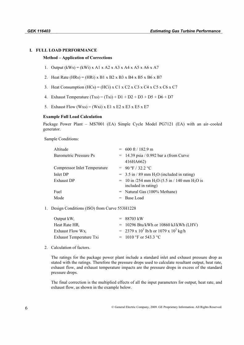
I. FULL LOAD PERFORMANCE
A. Method – Application of Corrections
1. Output (kWs) = (kWi) x A1 x A2 x A3 x A4 x A5 x A6 x A7
2. Heat Rate (HRs) = (HRi) x B1 x B2 x B3 x B4 x B5 x B6 x B7
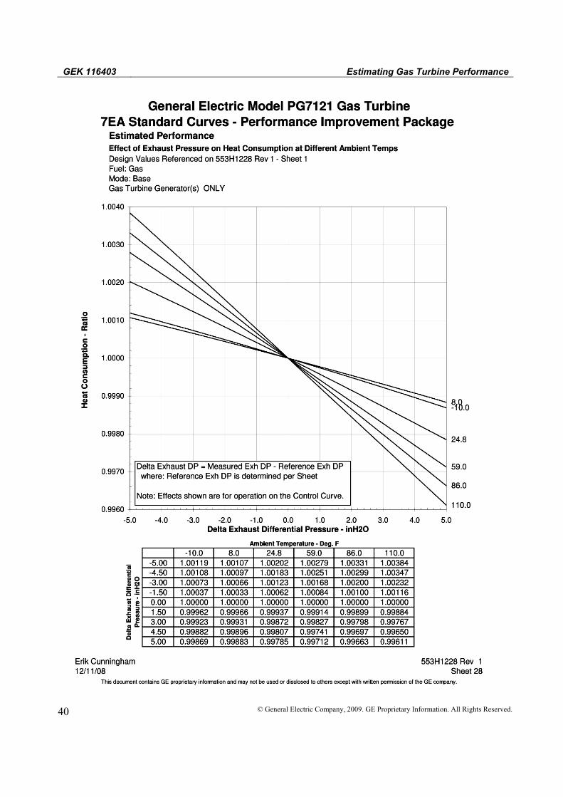
3. Heat Consumption (HCs) = (HCi) x C1 x C2 x C3 x C4 x C5 x C6 x C7
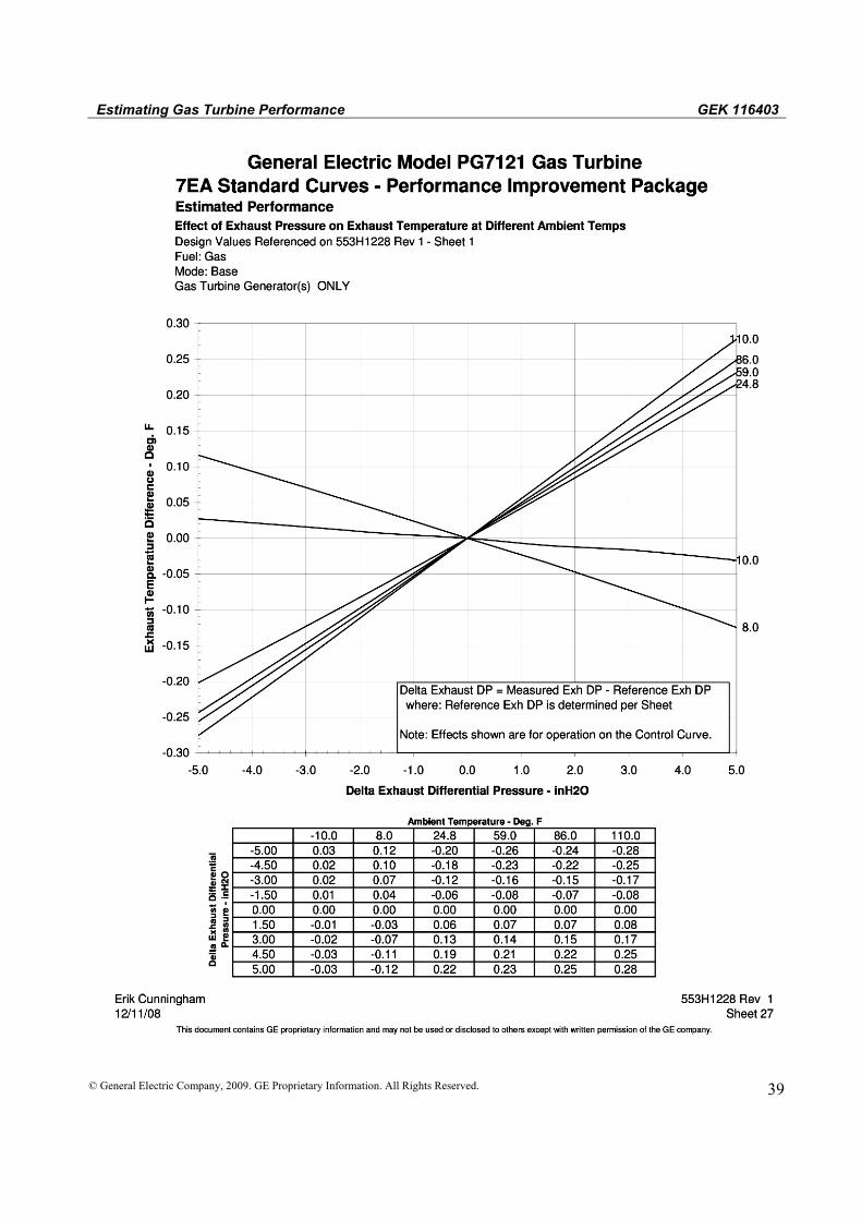
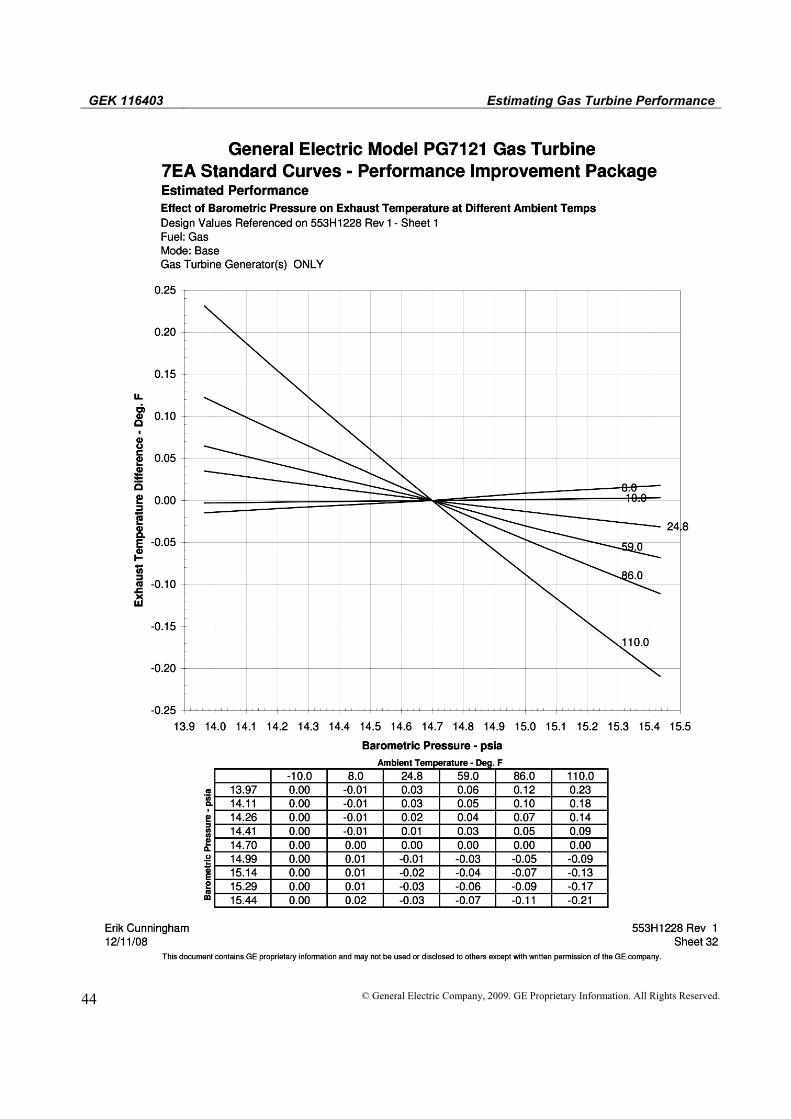
4. Exhaust Temperature (Txs) = (Txi) + D1 + D2 + D3 + D5 + D6 + D7
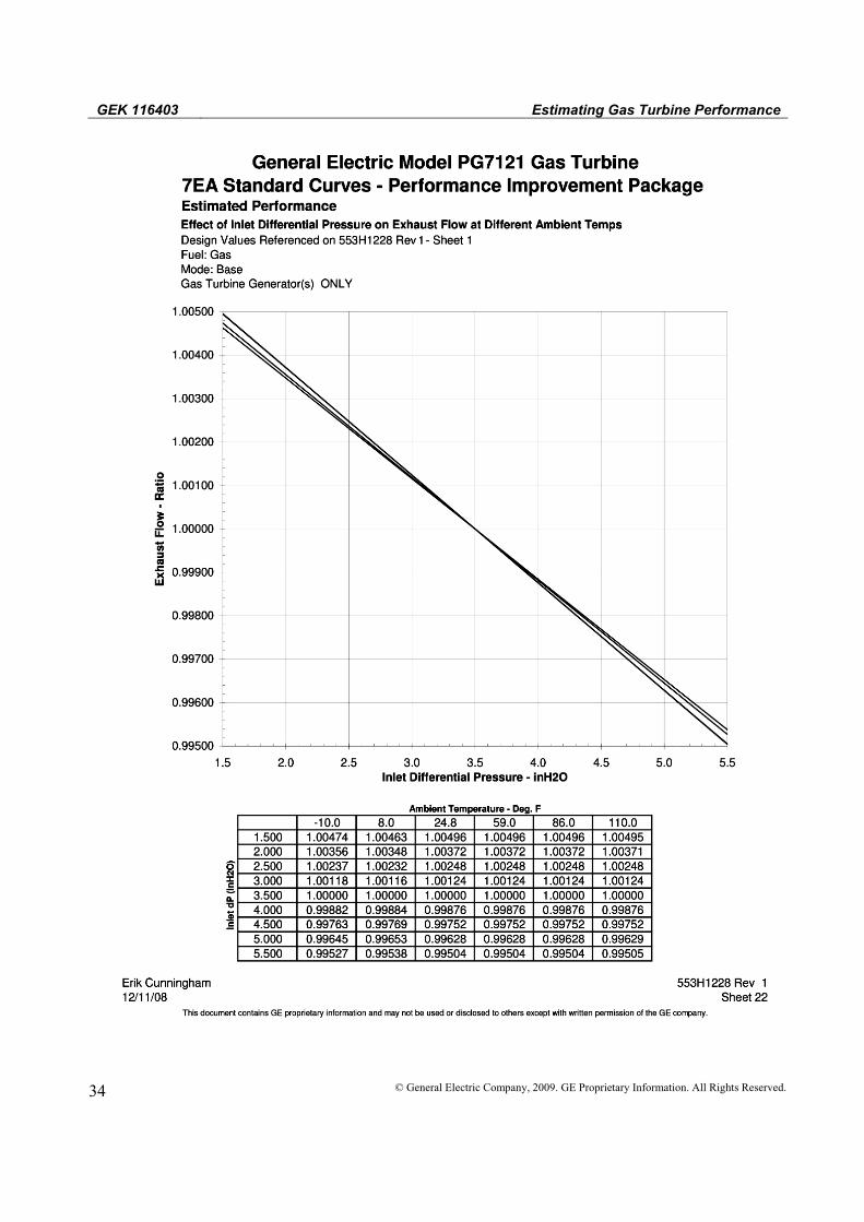
5. Exhaust Flow (Wxs) = (Wxi) x E1 x E2 x E3 x E5 x E7
B. Example Full Load Calculation
Package Power Plant – MS7001 (EA) Simple Cycle Model PG7121 (EA) with an air–cooled generator.
Sample Conditions:
Altitude = 600 ft / 182.9 m Barometric Pressure Ps = 14.39 psia / 0.992 bar a (from Curve 416HA662) Compressor Inlet Temperature = 90 ºF / 32.2 °C
Inlet DP = 3.5 in / 89 mm H2O (included in rating) Exhaust DP = 10 in /254 mm H2O (5.5 in / 140 mm H2O is
included in rating) Fuel = Natural Gas (100% Methane) Mode = Base Load
1. Design Conditions (ISO) from Curve 553H1228
Output kWi = 88703 kW Heat Rate HRi = 10296 Btu/kWh or 10860 kJ/kWh (LHV) Exhaust Flow Wxi = 2379 x 103 lb/h or 1079 x 103 kg/h Exhaust Temperature Txi = 1010 °F or 543.3 °C
2. Calculation of factors.
The ratings for the package power plant include a standard inlet and exhaust pressure drop as stated with the ratings. Therefore the pressure drops used to calculate resultant output, heat rate, exhaust flow, and exhaust temperature impacts are the pressure drops in excess of the standard pressure drops.
The final correction is the multiplied effects of all the input parameters for output, heat rate, and exhaust flow, as shown in the example below.

Estimating Gas Turbine Performance GEK 116403
© General Electric Company, 2009. GE Proprietary Information. All Rights Reserved. 7
Output : A1 = 0.8880 (90°F/32.2°C -Sheet 2)
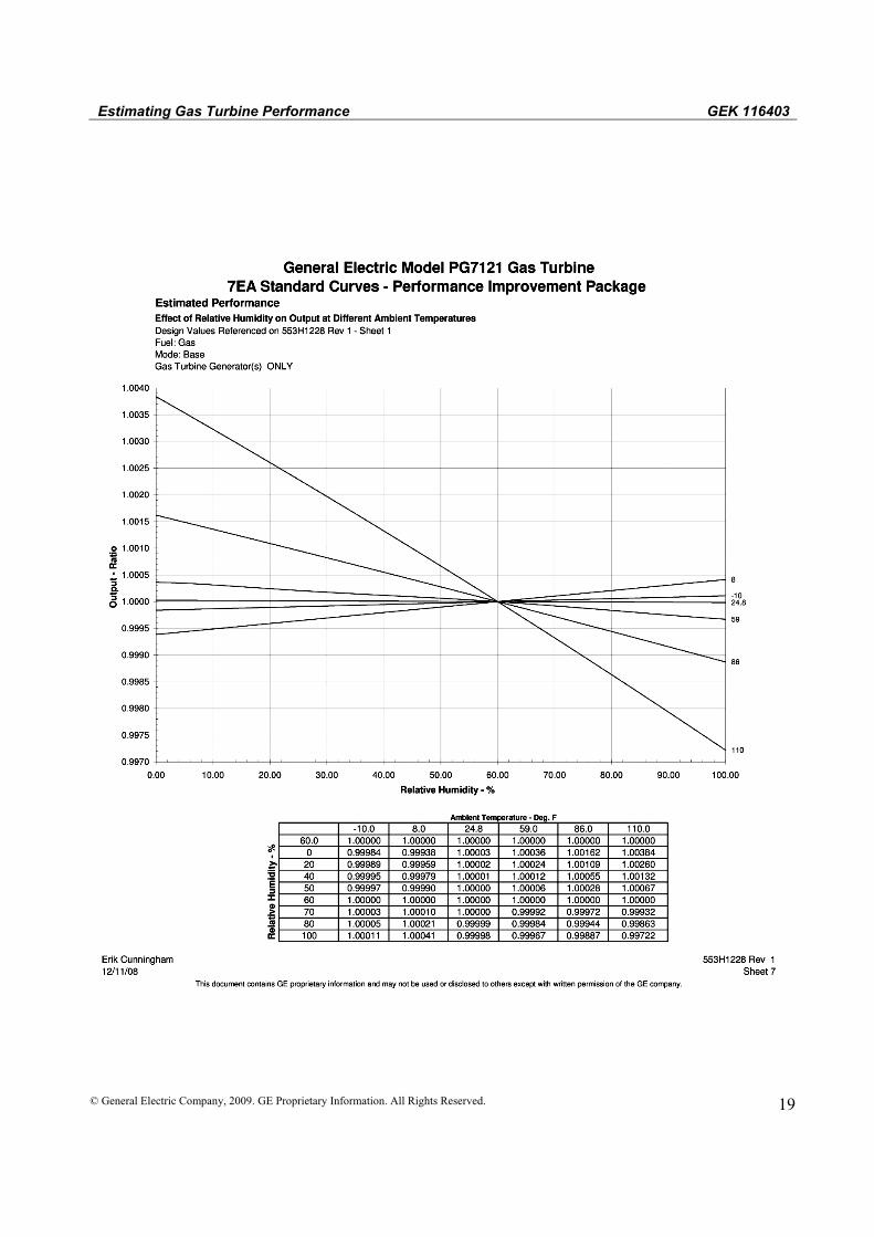
A2 = 1.0 (60% RH- Sheet 7)
A3 = 1.0 (3600 rpm – Sheet 12)
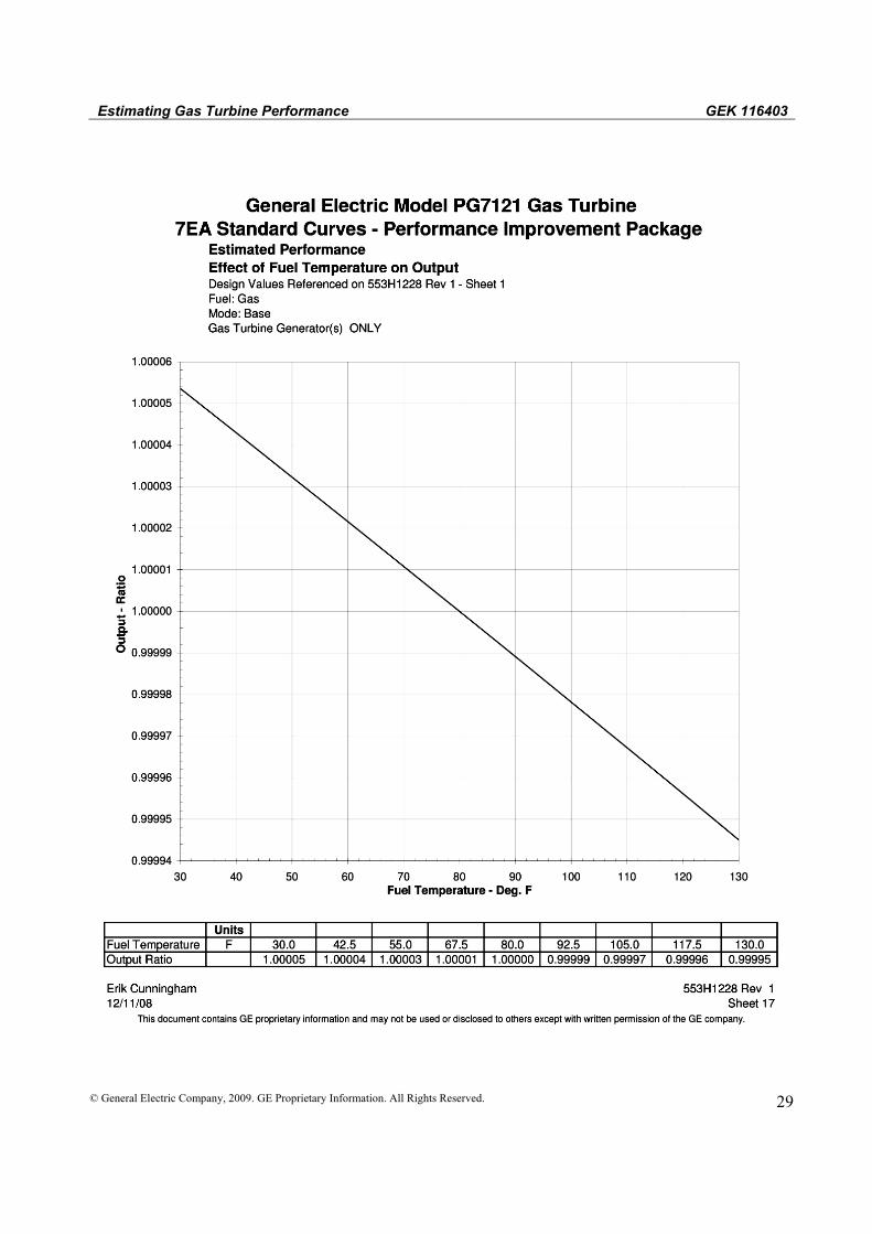
A4 = 1.0 (80°F/26.7°C Fuel Temp-Sheet 17)
A5 = 1.0 (3.5 in / 89 mm H2O inlet-Sheet 20)
A6 = 0.9904 (10-5.5=4.5 in / 114 mm H2O at 90°F/32.2°C -Sheet 25)
A7 = 0.9780 (14.39 psia/0.992 bar a at 90°F/32.2°C -Sheet 29)
Total Correction = 0.8880 x 1.0 x 1.0 x 1.0 x 1.0 x 0.9904 x 0.9780
= 0.86012
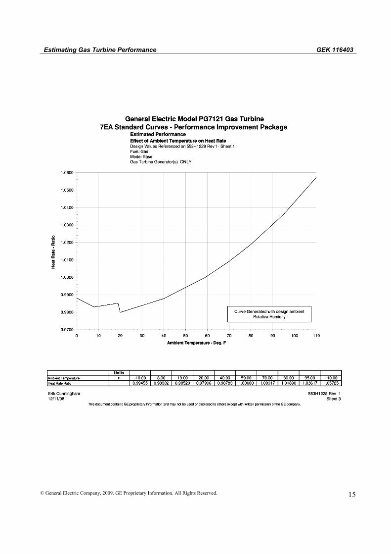
Heat Rate : B1 = 1.03 (90°F/32.2°C -Sheet 3)
B2 = 1.0 (60% RH-Sheet 8)
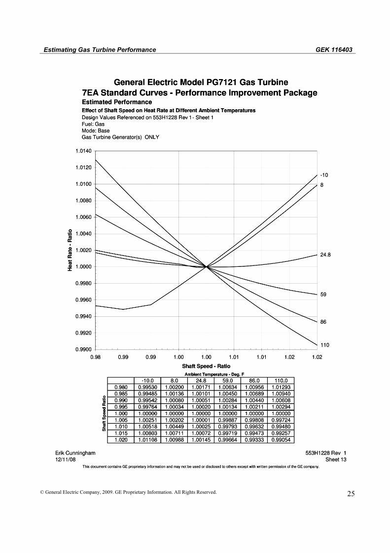
B3 = 1.0 (3600rpm – Sheet 13)
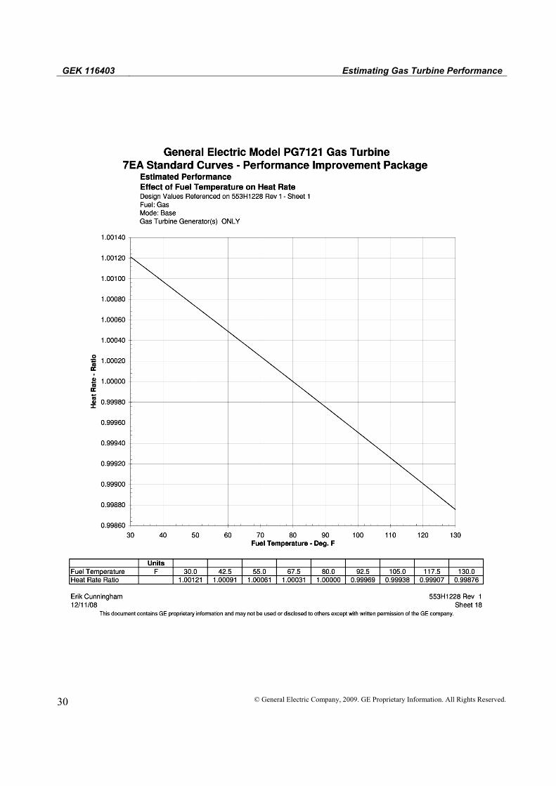
B4 = 1.0 (80°F/26.7°C Fuel Temp – Sheet 18)
B5 = 1.0 (3.5 in / 89 mm H2O inlet-Sheet 21)
B6 = 1.007 (10-5.5=4.5 in/114 mm H2O at 90°F/32.2°C-Sheet 26)
B7 = 1.0008 (14.39 psia/0.992 bar a at 90°F/32.2°C -Sheet 30)
Total Correction = 1.03 x 1.0 x 1.0 x 1.0 x 1.0 x 1.007 x 1.0008
= 1.038

GEK 116403 Estimating Gas Turbine Performance
8 © General Electric Company, 2009. GE Proprietary Information. All Rights Reserved.
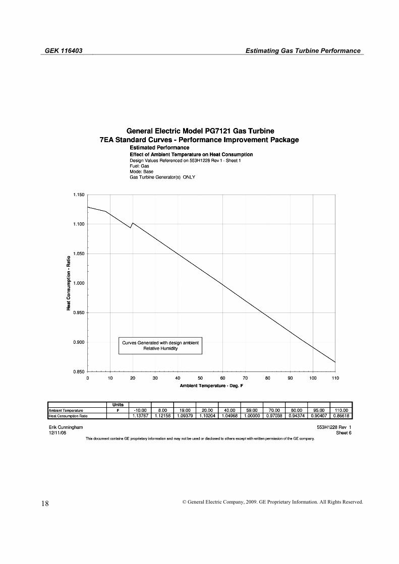
Heat Consumption C1 = 0.917 (90°F/32.2°C -Sheet 6)
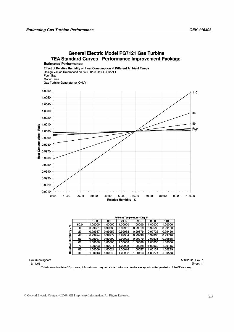
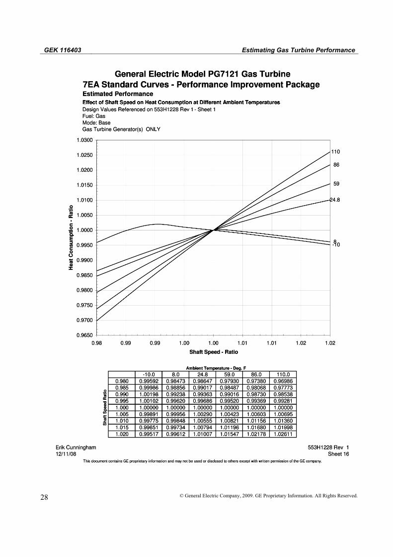
C2 = 1.0 (60% RH- Sheet 11) C3 = 1.0 (3600rpm – Sheet 16) C4 = 1.0 (80°F/26.7°C Fuel Temp – Sheet 19)
C5 = 1.0 (3.5 in/89 mm H2O inlet-Sheet 24) C6 = 0.997 (10-5.5=4.5 in/114 mm H2O at
90°F/32.2°C-Sheet 28)
C7 = 0.978 (14.39 psia/0.992 bara at 90°F/32.2°C-Sheet 33)
Total Correction 0.917 x 1.0 x 1.0 x 1.0 x 1.0 x 0.997 x 0.978 0.8941
Exhaust Temperature:
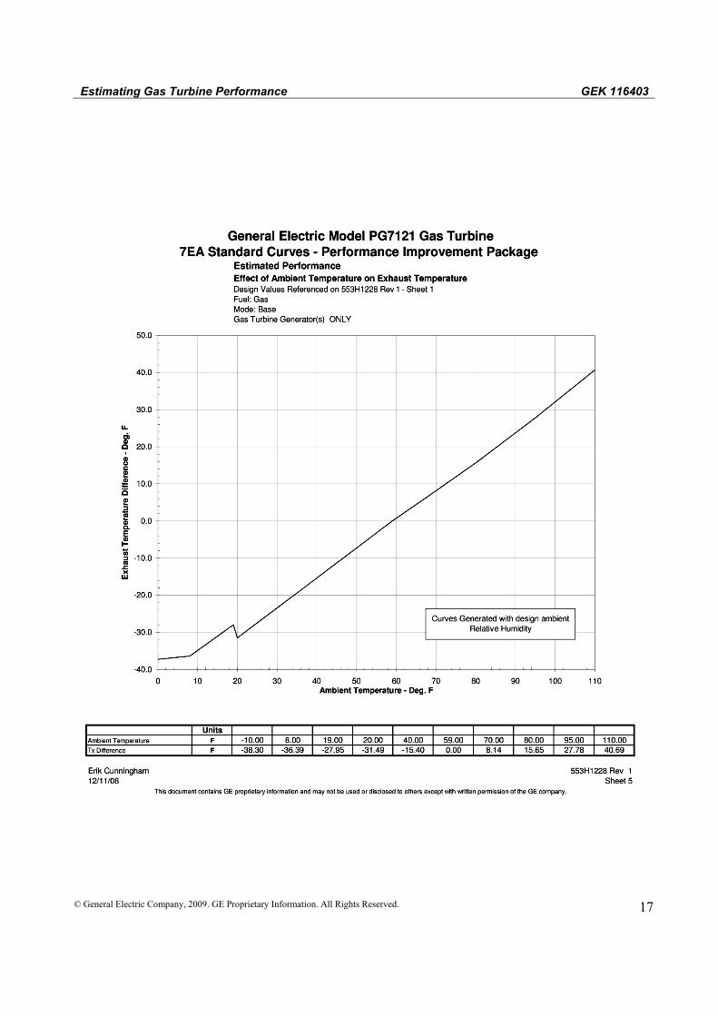
D1 = 23.7 (90°F/32.2°C -Sheet 5)
D2 = 0.0 (60% RH- Sheet 10) D3 = 0.0 (3600rpm – Sheet 15) D4 = 0.0 N/A D5 = 0.0 (3.5 in/89 mm H2O inlet-Sheet 23) D6 = 0.225 (10-5.5=4.5 in/114 mm H2O at
90°F/32.2°C -Sheet 27) D7 = 0.06 (14.39 psia/0.992 bar a at 90°F/32.2°C
-Sheet 32) Total Correction 23.7 + 0 + 0 + 0 + 0 + 0.225 + 0.06 24.0 Exhaust Flow E1 = 0.925 (90°F/32.2°C -Sheet 4)
E2 = 1.0 (60% RH- Sheet 9) E3 = 1.0 (3600rpm – Sheet 14) E4 = 1.0 N/A E5 = 1.0 (3.5in/89 mm H2O inlet-Sheet 22) E6 = 1.0 N/A E7 = 0.978 (14.39 psia/0.992 bar a at 90°F/32.2°C
-Sheet 31) 0.925 x 1.0 x 1.0 x 1.0 x 1.0 x 1.0 x 0.978 0.9047

Estimating Gas Turbine Performance GEK 116403
© General Electric Company, 2009. GE Proprietary Information. All Rights Reserved. 9
3. Calculation of Sample Full Load Conditions:
Exhaust temperature is calculated by adding the temperature increase due to ambient temperature and pressure drops to the design value read from Curve 553H1228:
II. PART LOAD PERFORMANCE
Part load output, heat rate and heat consumption are calculated in a similar manner as base load using the part load heat consumption curve. Before using the output percent from the heat consumption curve, all part load performance must be referenced to 59°F/15°C sample performance kWO
A. Method
1. At sample barometric pressure with sample inlet and exhaust pressure drops and at 59°F/15°C ambient temperature, calculate the following base load performance parameters:
Output, kWO
Heat rate, HRO
Heat consumption, HCO
Exhaust Flow, Wx0
Exhaust Temperature, Tx0
This data then becomes the corrected values on which to base the part load calculations.
2. Calculate percentage of load:
Percent load = required load/KwO
3. From the applicable performance curve, at the percent of load calculated from (2) above and at the compressor inlet temperature, read the percent of design heat rate.
HRs = HRo x % design heat consumption.
Output kWS = 88703 x 0.86012=76295 kW Heat Rate HRS =
10296 x 1.038=10687 Btu/kWh or 11273 kJ/kWh (LHV)
Heat Consumption HCS =88703 x 10296 x 0.8941=816.6 x 10⁶ Btu/h or 861.3 kJ/h (LVH)
Exhaust Temp Tx = 1010°F + 24.0°F=1034°F or 556.7 °C
Exhaust Flow = 2379 x 0.9047=2152.3 x103 lb/h or 976.3 x 10³ kg/h
GEK 116403 Estimating Gas Turbine Performance
10 © General Electric Company, 2009. GE Proprietary Information. All Rights Reserved.
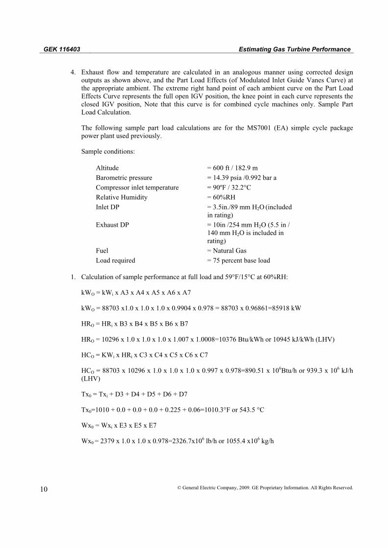
4. Exhaust flow and temperature are calculated in an analogous manner using corrected design outputs as shown above, and the Part Load Effects (of Modulated Inlet Guide Vanes Curve) at the appropriate ambient. The extreme right hand point of each ambient curve on the Part Load Effects Curve represents the full open IGV position, the knee point in each curve represents the closed IGV position, Note that this curve is for combined cycle machines only. Sample Part Load Calculation.
The following sample part load calculations are for the MS7001 (EA) simple cycle package power plant used previously.
Sample conditions:
Altitude = 600 ft / 182.9 m Barometric pressure = 14.39 psia /0.992 bar a Compressor inlet temperature = 90ºF / 32.2°C Relative Humidity = 60%RH Inlet DP = 3.5in./89 mm H2O
(included in rating)
Exhaust DP = 10in /254 mm H2O (5.5 in / 140 mm H2O is included in rating)
Fuel = Natural Gas Load required = 75 percent base load
1. Calculation of sample performance at full load and 59°F/15°C at 60%RH:
kWO = kWi x A3 x A4 x A5 x A6 x A7
kWO = 88703 x1.0 x 1.0 x 1.0 x 0.9904 x 0.978 = 88703 x 0.96861=85918 kW
HRO = HRi x B3 x B4 x B5 x B6 x B7
HRO = 10296 x 1.0 x 1.0 x 1.0 x 1.007 x 1.0008=10376 Btu/kWh or 10945 kJ/kWh (LHV)
HCO = KWi x HRi x C3 x C4 x C5 x C6 x C7
HCO = 88703 x 10296 x 1.0 x 1.0 x 1.0 x 0.997 x 0.978=890.51 x 10⁶Btu/h or 939.3 x 10⁶ kJ/h (LHV)
Tx0 = Txi + D3 + D4 + D5 + D6 + D7
Tx0=1010 + 0.0 + 0.0 + 0.0 + 0.225 + 0.06=1010.3°F or 543.5 °C
Wx0 = Wxi x E3 x E5 x E7
Wx0 = 2379 x 1.0 x 1.0 x 0.978=2326.7x106 lb/h or 1055.4 x106 kg/h

Estimating Gas Turbine Performance GEK 116403
© General Electric Company, 2009. GE Proprietary Information. All Rights Reserved. 11
2. Calculation of sample performance for 90°F/32.2°C @ 60%RH:
Sample output (base load) = kWO A1 x A2
= 85918 x 0.888 x 1.0 = 76295 kW
At 75% base load, required load = 76295 x 0.75 = 57221 kW,
The percent load at sample conditions (59°F/15°C) = 57221/85919 = 66.6%
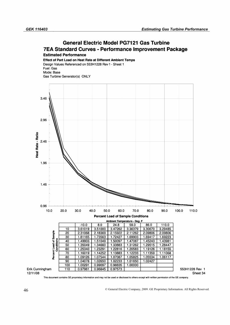
3. From Curve 553H1228 Sheet 34 at 66.6% design load and 90°F/32.2°C, Heat Rate-Ratio = 113.9%
Part load, sample heat rate, HRS = HR0 x Heat Rate-Ratio
HRs = 10376 x 1.139 = 11818 Btu/kWh or 12466 kJ/kWh (LHV)
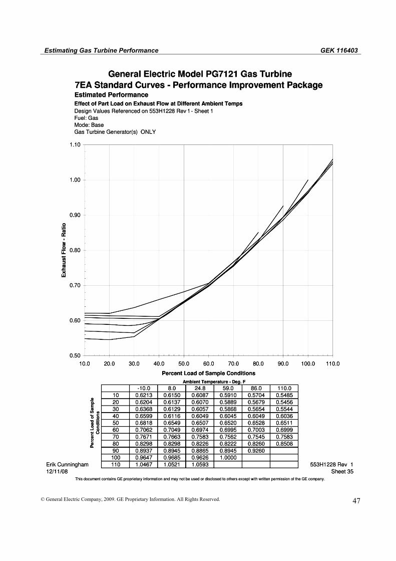
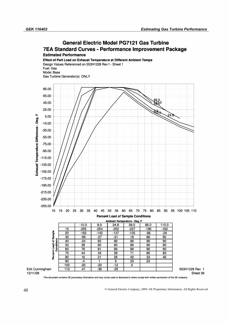
4. Entering the Part Load Effects Curve (553H1228 Sheet 35 & 35) at the 66.6% output calculated in Step 2 and, for the 90°F/32.2°C ambient curve;
Exhaust Temp Diff = 84°F
TxS = Tx0+Exh Temp Diff=1010.3 + 84=1094.3°F or 590.2 °C
Exhaust Flow-Ratio = 73.6%
WxS = Wx0 x Exhaust Flow-Ratio= 2326.7 x 0.736 = 1712 x 103 lb/h or 776.6 x 10³ kg/h
Performance with Water or Steam Injection
The amount of steam or water injection required to meet a given NOx emission level is not available from a curve because of the many variables impacting this value. In fact, the exact flow is typically not finalized until the field Emissions Compliance Testing. However, given a specific flow value, the resulting effect on output and Heat Rate can be determined using the Injection Effects Curves.
For example, taking the “dry” Output and Heat Rate Performance calculated from Example I and, assuming GE has reported (for the specific conditions given) an estimated steam flow of 64760 lb/h or 29370 kg/h (18 lb/s or 8.16 kg/s); The resulting output and heat rate would be:
kW = 76295 x (1.088) (from curve 553H1228 page 37 at 90°F/32.2°C)
= 83008 kW
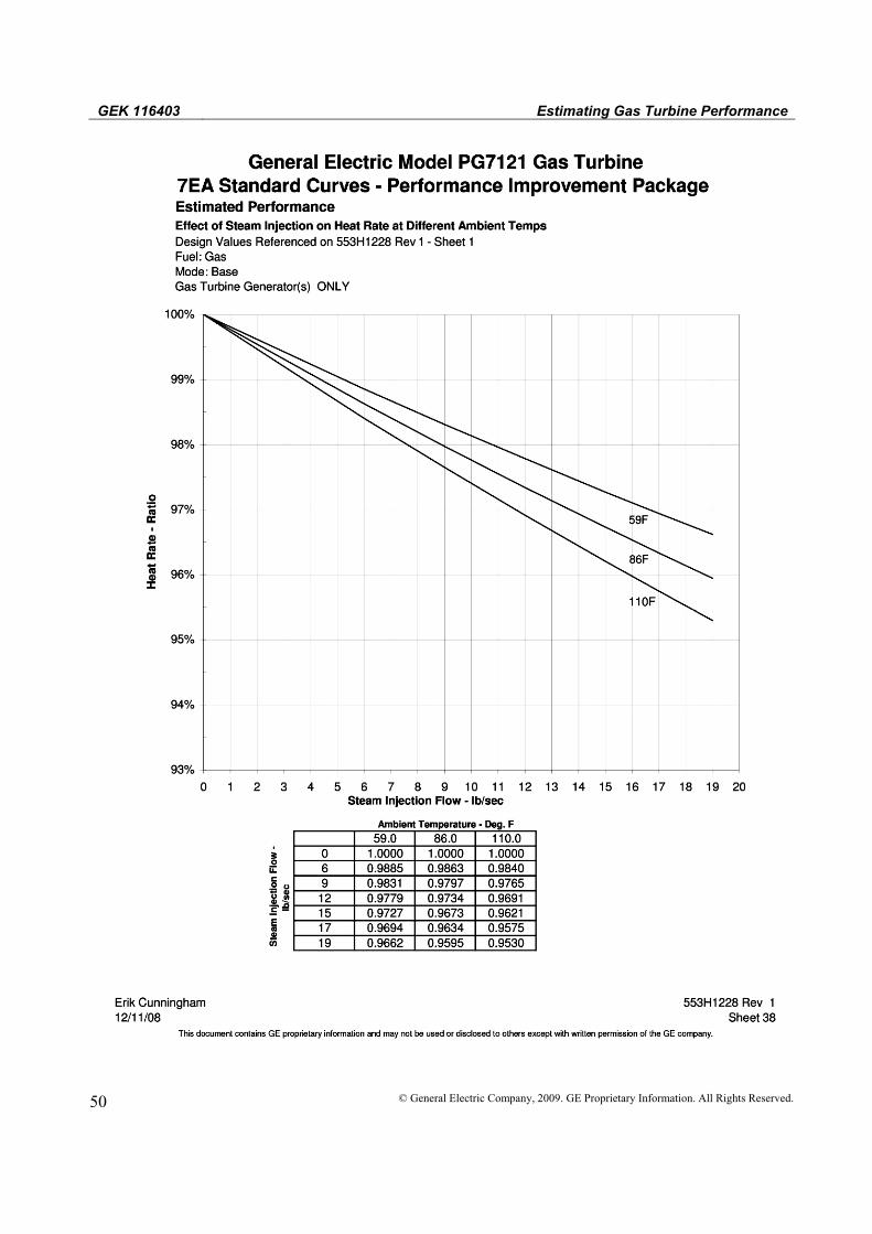
HR = 10687 x (0.9604) (from curve 533H1228 page 38 at 90°F/32.2°C)
= 10264 Btu/kW–h (LHV) or 10826 kJ/kWh (LHV)

GEK 116403 Estimating Gas Turbine Performance
12 © General Electric Company, 2009. GE Proprietary Information. All Rights Reserved.
Si and Metric Units Conversion
The following is a list of conversion factors most commonly used for gas turbine performance calculations. Conversion Factors To Convert To Multiply By Atm kg/cm2 1.0333 Atm lb/in2 14.7 Bars atm 0.9869 Bars lb/in2 14.5 Btu/h kcal/h 0.2520 Btu/h kJ/h 1.0548 Btu/hph kJ/kWh 1.4148 Btu/lb kJ/kg 2.326 ºF ºR ºF + 459.7 ºC ºF (ºC x 9/5) + 32 ºC ºK ºC + 273.2 Ft3/min l/s 0.4720 Ft3/min m3/min 0.02832 gal/mln l/s 0.06308 In. of mercury kg/cm2 0.03453 In. of water (at 4ºC) kg/cm2 0.00254 in. of water (at 4ºC) lb/in2 0.03613 J Btu 9.478 x 10⁻⁴
kg lb 2.205 kg/cm2 lb/in2 14.22 kg/m3 lb/ft3 0.06243 kW hp 1.341 lb/in2 Pa 6894.8 l/min ft3/s 5.886 x 10⁻⁴
l/min gal/s 0.004403 scf Nm3 0.0268 W Btu/h 3.4129

Estimating Gas Turbine Performance GEK 116403
© General Electric Company, 2009. GE Proprietary Information. All Rights Reserved. 13
B. 553H1228 PG7121 PIP Gen Drive

GEK 116403 Estimating Gas Turbine Performance
14 © General Electric Company, 2009. GE Proprietary Information. All Rights Reserved.
Estimating Gas Turbine Performance GEK 116403
© General Electric Company, 2009. GE Proprietary Information. All Rights Reserved. 15

GEK 116403 Estimating Gas Turbine Performance
16 © General Electric Company, 2009. GE Proprietary Information. All Rights Reserved.
Estimating Gas Turbine Performance GEK 116403
© General Electric Company, 2009. GE Proprietary Information. All Rights Reserved. 17
GEK 116403 Estimating Gas Turbine Performance
18 © General Electric Company, 2009. GE Proprietary Information. All Rights Reserved.
Estimating Gas Turbine Performance GEK 116403
© General Electric Company, 2009. GE Proprietary Information. All Rights Reserved. 19

GEK 116403 Estimating Gas Turbine Performance
20 © General Electric Company, 2009. GE Proprietary Information. All Rights Reserved.

Estimating Gas Turbine Performance GEK 116403
© General Electric Company, 2009. GE Proprietary Information. All Rights Reserved. 21

GEK 116403 Estimating Gas Turbine Performance
22 © General Electric Company, 2009. GE Proprietary Information. All Rights Reserved.
Estimating Gas Turbine Performance GEK 116403
© General Electric Company, 2009. GE Proprietary Information. All Rights Reserved. 23

GEK 116403 Estimating Gas Turbine Performance
24 © General Electric Company, 2009. GE Proprietary Information. All Rights Reserved.
Estimating Gas Turbine Performance GEK 116403
© General Electric Company, 2009. GE Proprietary Information. All Rights Reserved. 25

GEK 116403 Estimating Gas Turbine Performance
26 © General Electric Company, 2009. GE Proprietary Information. All Rights Reserved.

Estimating Gas Turbine Performance GEK 116403
© General Electric Company, 2009. GE Proprietary Information. All Rights Reserved. 27
GEK 116403 Estimating Gas Turbine Performance
28 © General Electric Company, 2009. GE Proprietary Information. All Rights Reserved.
Estimating Gas Turbine Performance GEK 116403
© General Electric Company, 2009. GE Proprietary Information. All Rights Reserved. 29
GEK 116403 Estimating Gas Turbine Performance
30 © General Electric Company, 2009. GE Proprietary Information. All Rights Reserved.

Estimating Gas Turbine Performance GEK 116403
© General Electric Company, 2009. GE Proprietary Information. All Rights Reserved. 31

GEK 116403 Estimating Gas Turbine Performance
32 © General Electric Company, 2009. GE Proprietary Information. All Rights Reserved.

Estimating Gas Turbine Performance GEK 116403
© General Electric Company, 2009. GE Proprietary Information. All Rights Reserved. 33
GEK 116403 Estimating Gas Turbine Performance
34 © General Electric Company, 2009. GE Proprietary Information. All Rights Reserved.

Estimating Gas Turbine Performance GEK 116403
© General Electric Company, 2009. GE Proprietary Information. All Rights Reserved. 35

GEK 116403 Estimating Gas Turbine Performance
36 © General Electric Company, 2009. GE Proprietary Information. All Rights Reserved.

Estimating Gas Turbine Performance GEK 116403
© General Electric Company, 2009. GE Proprietary Information. All Rights Reserved. 37

GEK 116403 Estimating Gas Turbine Performance
38 © General Electric Company, 2009. GE Proprietary Information. All Rights Reserved.
Estimating Gas Turbine Performance GEK 116403
© General Electric Company, 2009. GE Proprietary Information. All Rights Reserved. 39
GEK 116403 Estimating Gas Turbine Performance
40 © General Electric Company, 2009. GE Proprietary Information. All Rights Reserved.

Estimating Gas Turbine Performance GEK 116403
© General Electric Company, 2009. GE Proprietary Information. All Rights Reserved. 41

GEK 116403 Estimating Gas Turbine Performance
42 © General Electric Company, 2009. GE Proprietary Information. All Rights Reserved.

Estimating Gas Turbine Performance GEK 116403
© General Electric Company, 2009. GE Proprietary Information. All Rights Reserved. 43
GEK 116403 Estimating Gas Turbine Performance
44 © General Electric Company, 2009. GE Proprietary Information. All Rights Reserved.

Estimating Gas Turbine Performance GEK 116403
© General Electric Company, 2009. GE Proprietary Information. All Rights Reserved. 45
GEK 116403 Estimating Gas Turbine Performance
46 © General Electric Company, 2009. GE Proprietary Information. All Rights Reserved.
Estimating Gas Turbine Performance GEK 116403
© General Electric Company, 2009. GE Proprietary Information. All Rights Reserved. 47
GEK 116403 Estimating Gas Turbine Performance
48 © General Electric Company, 2009. GE Proprietary Information. All Rights Reserved.

Estimating Gas Turbine Performance GEK 116403
© General Electric Company, 2009. GE Proprietary Information. All Rights Reserved. 49
GEK 116403 Estimating Gas Turbine Performance
50 © General Electric Company, 2009. GE Proprietary Information. All Rights Reserved.

Estimating Gas Turbine Performance GEK 116403
© General Electric Company, 2009. GE Proprietary Information. All Rights Reserved. 51

GEK 116403 Estimating Gas Turbine Performance
52 © General Electric Company, 2009. GE Proprietary Information. All Rights Reserved.

Estimating Gas Turbine Performance GEK 116403
© General Electric Company, 2009. GE Proprietary Information. All Rights Reserved. 53

GEK 116403 Estimating Gas Turbine Performance
54 © General Electric Company, 2009. GE Proprietary Information. All Rights Reserved.
g GE Energy General Electric Company
www.gepower.com