gear pumps - national distribution gear pump catalog no address r0517 web.pdf · 3 table of...
TRANSCRIPT
Gear Pumps
2017Edition

3
Table of Contents
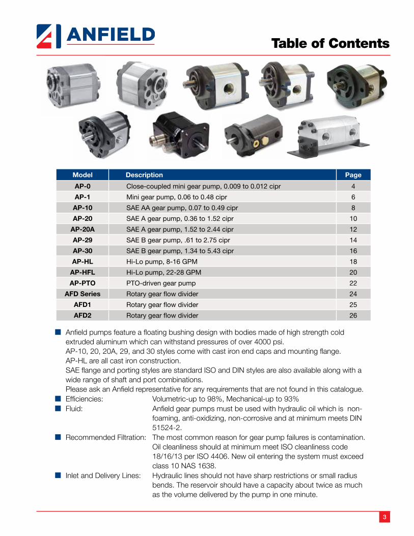
n Anfield pumps feature a floating bushing design with bodies made of high strength cold extruded aluminum which can withstand pressures of over 4000 psi.
AP-10, 20, 20A, 29, and 30 styles come with cast iron end caps and mounting flange. AP-HL are all cast iron construction. SAE flange and porting styles are standard ISO and DIN styles are also available along with a
wide range of shaft and port combinations. Please ask an Anfield representative for any requirements that are not found in this catalogue.n Efficiencies: Volumetric-up to 98%, Mechanical-up to 93%n Fluid: Anfield gear pumps must be used with hydraulic oil which is non-
foaming, anti-oxidizing, non-corrosive and at minimum meets DIN 51524-2.
n Recommended Filtration: The most common reason for gear pump failures is contamination.Oil cleanliness should at minimum meet ISO cleanliness code 18/16/13 per ISO 4406. New oil entering the system must exceed class 10 NAS 1638.
n Inlet and Delivery Lines: Hydraulic lines should not have sharp restrictions or small radius bends. The reservoir should have a capacity about twice as much as the volume delivered by the pump in one minute.
Model Description Page
AP-0 Close-coupled mini gear pump, 0.009 to 0.012 cipr 4
AP-1 Mini gear pump, 0.06 to 0.48 cipr 6
AP-10 SAE AA gear pump, 0.07 to 0.49 cipr 8
AP-20 SAE A gear pump, 0.36 to 1.52 cipr 10
AP-20A SAE A gear pump, 1.52 to 2.44 cipr 12
AP-29 SAE B gear pump, .61 to 2.75 cipr 14
AP-30 SAE B gear pump, 1.34 to 5.43 cipr 16
AP-HL Hi-Lo pump, 8-16 GPM 18
AP-HFL Hi-Lo pump, 22-28 GPM 20
AP-PTO PTO-driven gear pump 22
AFD Series Rotary gear flow divider 24
AFD1 Rotary gear flow divider 25
AFD2 Rotary gear flow divider 26
4
Hydraulic Gear Pump AP-0
DESCRIPTION
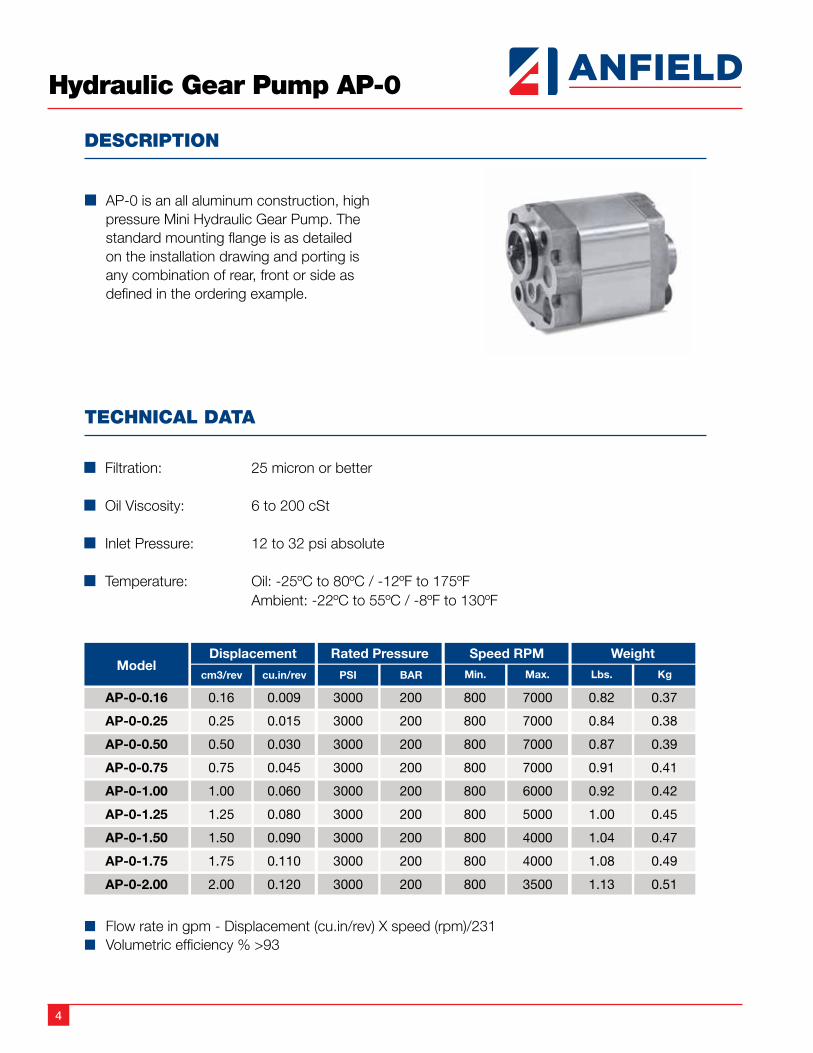
n AP-0 is an all aluminum construction, high pressure Mini Hydraulic Gear Pump. The standard mounting flange is as detailed on the installation drawing and porting is any combination of rear, front or side as defined in the ordering example.
TECHNICAL DATA
n Filtration: 25 micron or better
n Oil Viscosity: 6 to 200 cSt
n Inlet Pressure: 12 to 32 psi absolute
n Temperature: Oil: -25ºC to 80ºC / -12ºF to 175ºF Ambient: -22ºC to 55ºC / -8ºF to 130ºF
n Flow rate in gpm - Displacement (cu.in/rev) X speed (rpm)/231n Volumetric efficiency % >93
5
Hydraulic Gear Pump AP-0
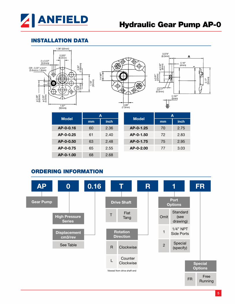
INSTALLATION DATA
ORDERING INFORMATION
6
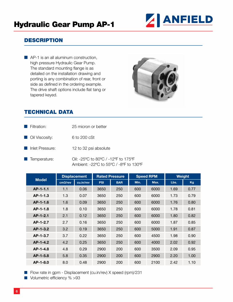
Hydraulic Gear Pump AP-1
DESCRIPTION
n AP-1 is an all aluminum construction, high pressure Hydraulic Gear Pump. The standard mounting flange is as detailed on the installation drawing and porting is any combination of rear, front or side as defined in the ordering example. The drive shaft options include flat tang or tapered keyed.
TECHNICAL DATA
n Filtration: 25 micron or better
n Oil Viscosity: 6 to 200 cSt
n Inlet Pressure: 12 to 32 psi absolute
n Temperature: Oil: -25ºC to 80ºC / -12ºF to 175ºF Ambient: -22ºC to 55ºC / -8ºF to 130ºF
n Flow rate in gpm - Displacement (cu.in/rev) X speed (rpm)/231n Volumetric efficiency % >93
7
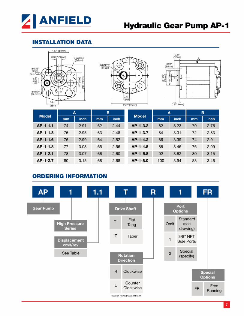
Hydraulic Gear Pump AP-1
INSTALLATION DATA
ORDERING INFORMATION
8
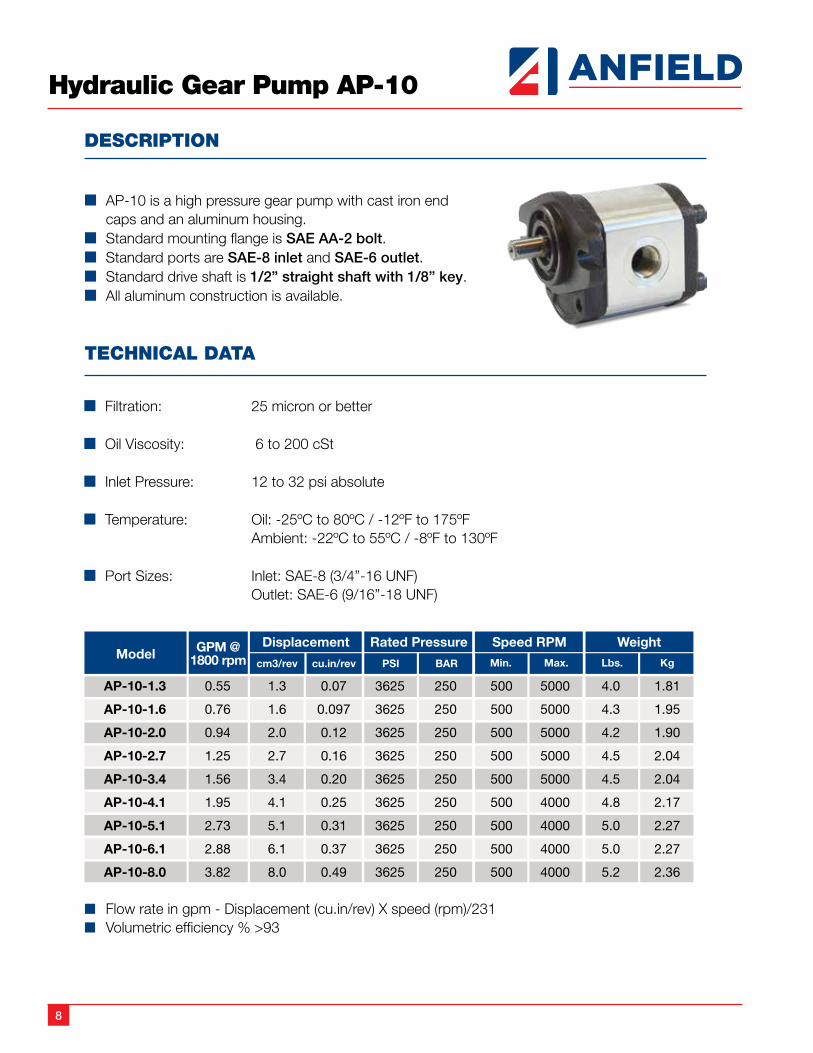
Hydraulic Gear Pump AP-10
DESCRIPTION
n AP-10 is a high pressure gear pump with cast iron end caps and an aluminum housing.
n Standard mounting flange is SAE AA-2 bolt.n Standard ports are SAE-8 inlet and SAE-6 outlet.n Standard drive shaft is 1/2” straight shaft with 1/8” key.n All aluminum construction is available.
TECHNICAL DATA
n Filtration: 25 micron or better
n Oil Viscosity: 6 to 200 cSt
n Inlet Pressure: 12 to 32 psi absolute
n Temperature: Oil: -25ºC to 80ºC / -12ºF to 175ºF Ambient: -22ºC to 55ºC / -8ºF to 130ºF
n Port Sizes: Inlet: SAE-8 (3/4”-16 UNF) Outlet: SAE-6 (9/16”-18 UNF)
n Flow rate in gpm - Displacement (cu.in/rev) X speed (rpm)/231n Volumetric efficiency % >93
9
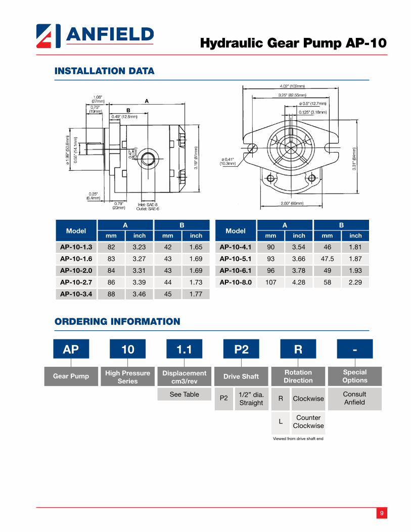
Hydraulic Gear Pump AP-10
INSTALLATION DATA
ORDERING INFORMATION
10
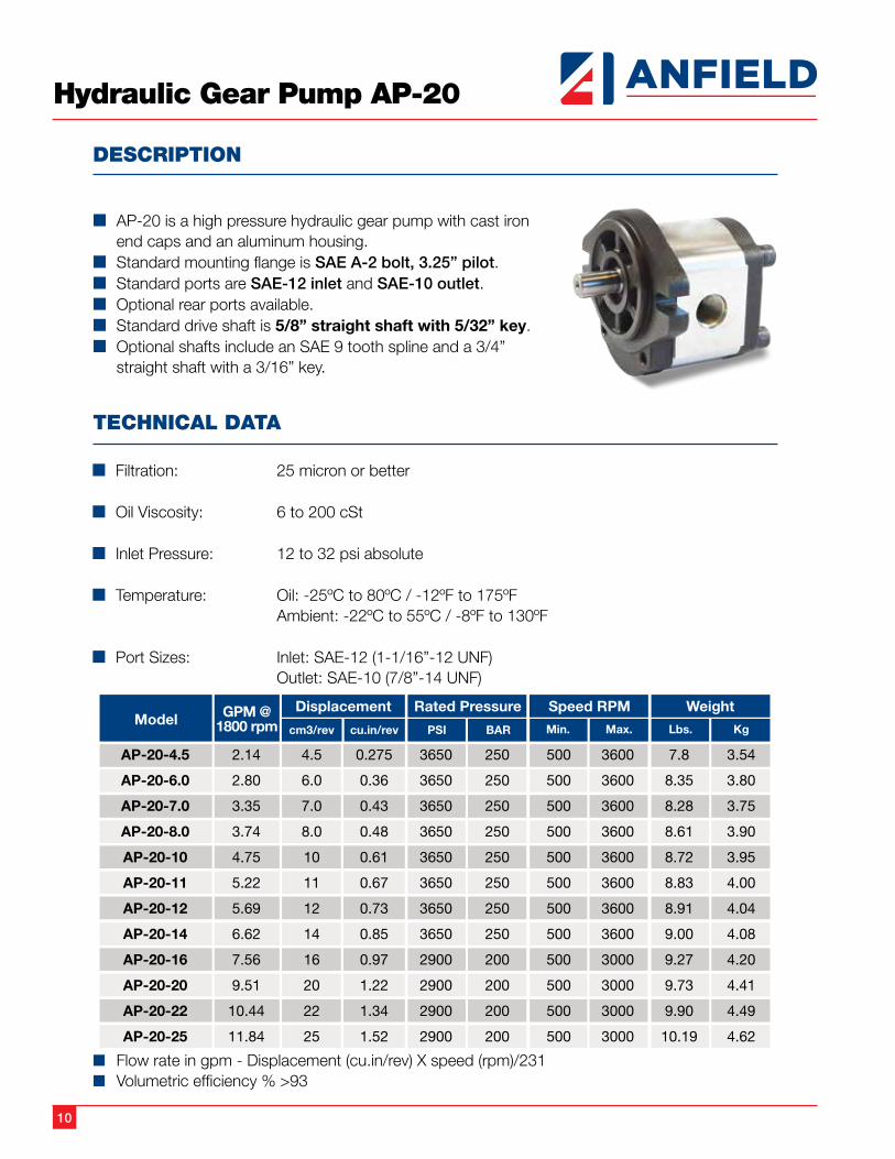
Hydraulic Gear Pump AP-20
DESCRIPTION
n AP-20 is a high pressure hydraulic gear pump with cast iron end caps and an aluminum housing.
n Standard mounting flange is SAE A-2 bolt, 3.25” pilot. n Standard ports are SAE-12 inlet and SAE-10 outlet.n Optional rear ports available.n Standard drive shaft is 5/8” straight shaft with 5/32” key.n Optional shafts include an SAE 9 tooth spline and a 3/4”
straight shaft with a 3/16” key.
TECHNICAL DATA
n Filtration: 25 micron or better
n Oil Viscosity: 6 to 200 cSt
n Inlet Pressure: 12 to 32 psi absolute
n Temperature: Oil: -25ºC to 80ºC / -12ºF to 175ºF Ambient: -22ºC to 55ºC / -8ºF to 130ºF
n Port Sizes: Inlet: SAE-12 (1-1/16”-12 UNF) Outlet: SAE-10 (7/8”-14 UNF)
n Flow rate in gpm - Displacement (cu.in/rev) X speed (rpm)/231n Volumetric efficiency % >93
11
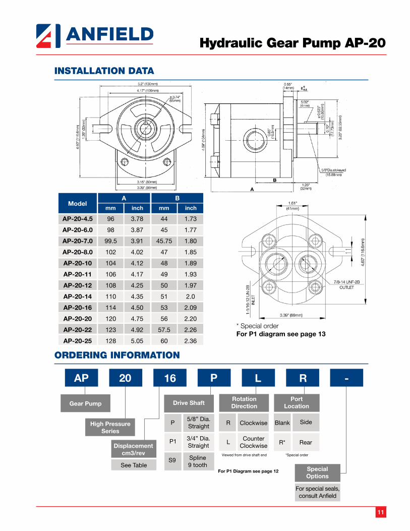
Hydraulic Gear Pump AP-20
INSTALLATION DATA
ORDERING INFORMATION
* Special orderFor P1 diagram see page 13
12
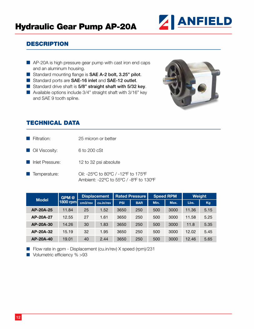
Hydraulic Gear Pump AP-20A
DESCRIPTION
n AP-20A is high pressure gear pump with cast iron end caps and an aluminum housing.
n Standard mounting flange is SAE A-2 bolt, 3.25” pilot. n Standard ports are SAE-16 inlet and SAE-12 outlet.n Standard drive shaft is 5/8” straight shaft with 5/32 key.n Available options include 3/4” straight shaft with 3/16” key
and SAE 9 tooth spline.
TECHNICAL DATA
n Filtration: 25 micron or better
n Oil Viscosity: 6 to 200 cSt
n Inlet Pressure: 12 to 32 psi absolute
n Temperature: Oil: -25ºC to 80ºC / -12ºF to 175ºF Ambient: -22ºC to 55ºC / -8ºF to 130ºF
n Flow rate in gpm - Displacement (cu.in/rev) X speed (rpm)/231n Volumetric efficiency % >93
13
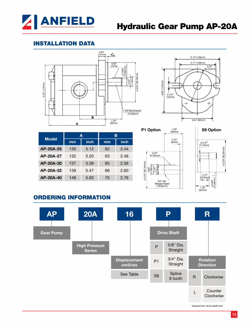
Hydraulic Gear Pump AP-20A
INSTALLATION DATA
ORDERING INFORMATION
P1 Option S9 Option
14
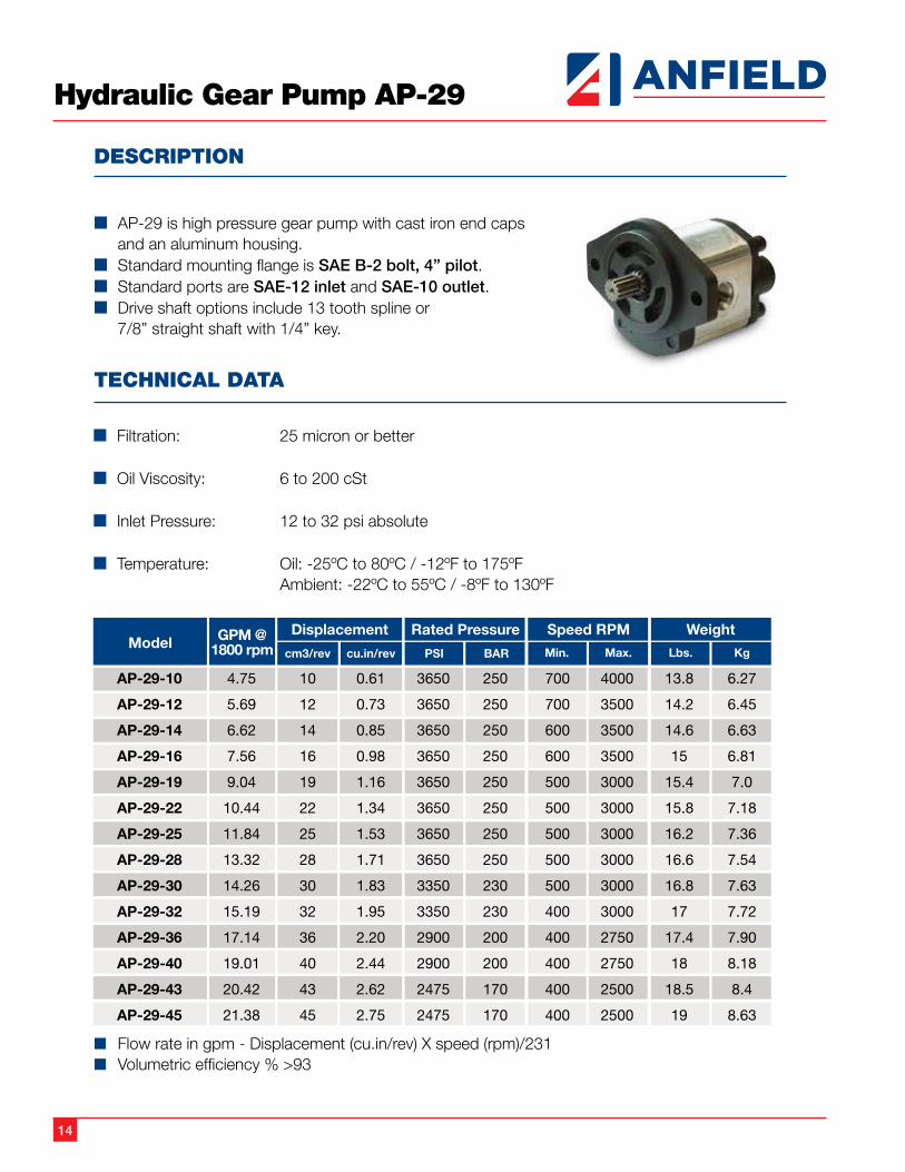
Hydraulic Gear Pump AP-29
DESCRIPTION
n AP-29 is high pressure gear pump with cast iron end caps and an aluminum housing.
n Standard mounting flange is SAE B-2 bolt, 4” pilot. n Standard ports are SAE-12 inlet and SAE-10 outlet.n Drive shaft options include 13 tooth spline or 7/8” straight shaft with 1/4” key.
TECHNICAL DATA
n Filtration: 25 micron or better
n Oil Viscosity: 6 to 200 cSt
n Inlet Pressure: 12 to 32 psi absolute
n Temperature: Oil: -25ºC to 80ºC / -12ºF to 175ºF Ambient: -22ºC to 55ºC / -8ºF to 130ºF
n Flow rate in gpm - Displacement (cu.in/rev) X speed (rpm)/231n Volumetric efficiency % >93
Model GPM @1800 rpm
Displacement Rated Pressure Speed RPM Weight
cm3/rev cu.in/rev PSI BAR Min. Max. Lbs. Kg
AP-29-10
AP-29-12
AP-29-14
AP-29-16
AP-29-19
AP-29-22
AP-29-25
AP-29-28
AP-29-30
AP-29-32
AP-29-36
AP-29-40
AP-29-43
AP-29-45
10
12
14
16
19
22
25
28
30
32
36
40
43
45
0.61
0.73
0.85
0.98
1.16
1.34
1.53
1.71
1.83
1.95
2.20
2.44
2.62
2.75
3650
3650
3650
3650
3650
3650
3650
3650
3350
3350
2900
2900
2475
2475
250
250
250
250
250
250
250
250
230
230
200
200
170
170
700
700
600
600
500
500
500
500
500
400
400
400
400
400
4000
3500
3500
3500
3000
3000
3000
3000
3000
3000
2750
2750
2500
2500
4.75
5.69
6.62
7.56
9.04
10.44
11.84
13.32
14.26
15.19
17.14
19.01
20.42
21.38
13.8
14.2
14.6
15
15.4
15.8
16.2
16.6
16.8
17
17.4
18
18.5
19
6.27
6.45
6.63
6.81
7.0
7.18
7.36
7.54
7.63
7.72
7.90
8.18
8.4
8.63
15
Hydraulic Gear Pump AP-29
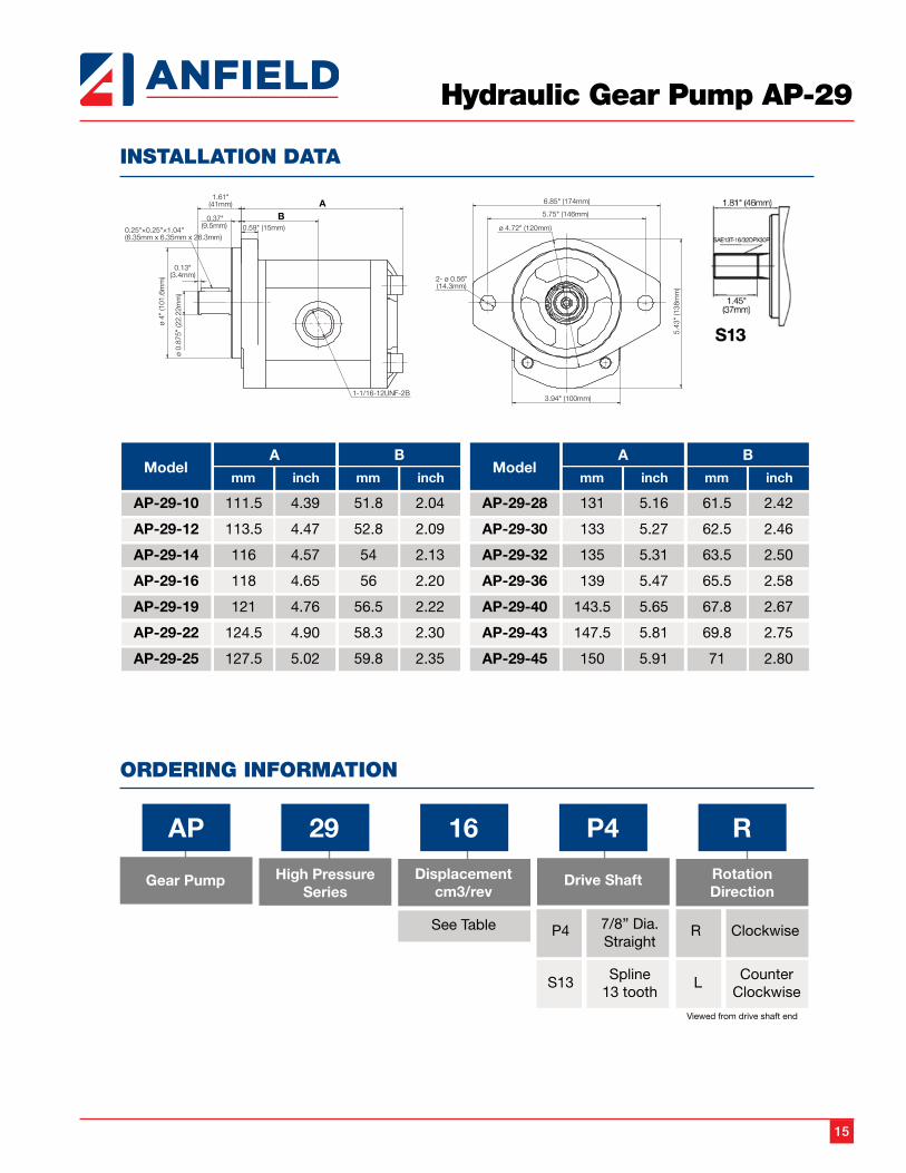
INSTALLATION DATA
ORDERING INFORMATION
Gear Pump High PressureSeries
AP 29 16 P4 R
Displacementcm3/rev
See Table
Drive Shaft
P4 7/8” Dia.Straight
S13 Spline13 tooth
RotationDirection
R Clockwise
L
Viewed from drive shaft end
CounterClockwise
6.85" (174mm)
5.75" (146mm)
2- ø 0.56"(14.3mm)
3.94" (100mm)
ø 4.72" (120mm)
5.43
" (1
38m
m)
ø 4"
(101
.6m
m)
0.37"(9.5mm)
0.59" (15mm)
AB
1.61"(41mm)
0.13"(3.4mm)
ø 0.
875"
(22.
22m
m)
1-1/16-12UNF-2B
0.25"×0.25"×1.04"(6.35mm x 6.35mm x 26.3mm)
ModelA
mm inch
B
mm inch
AP-29-10
AP-29-12
AP-29-14
AP-29-16
AP-29-19
AP-29-22
AP-29-25
111.5
113.5
116
118
121
124.5
127.5
4.39
4.47
4.57
4.65
4.76
4.90
5.02
51.8
52.8
54
56
56.5
58.3
59.8
2.04
2.09
2.13
2.20
2.22
2.30
2.35
ModelA
mm inch
B
mm inch
AP-29-28
AP-29-30
AP-29-32
AP-29-36
AP-29-40
AP-29-43
AP-29-45
131
133
135
139
143.5
147.5
150
5.16
5.27
5.31
5.47
5.65
5.81
5.91
61.5
62.5
63.5
65.5
67.8
69.8
71
2.42
2.46
2.50
2.58
2.67
2.75
2.80
16
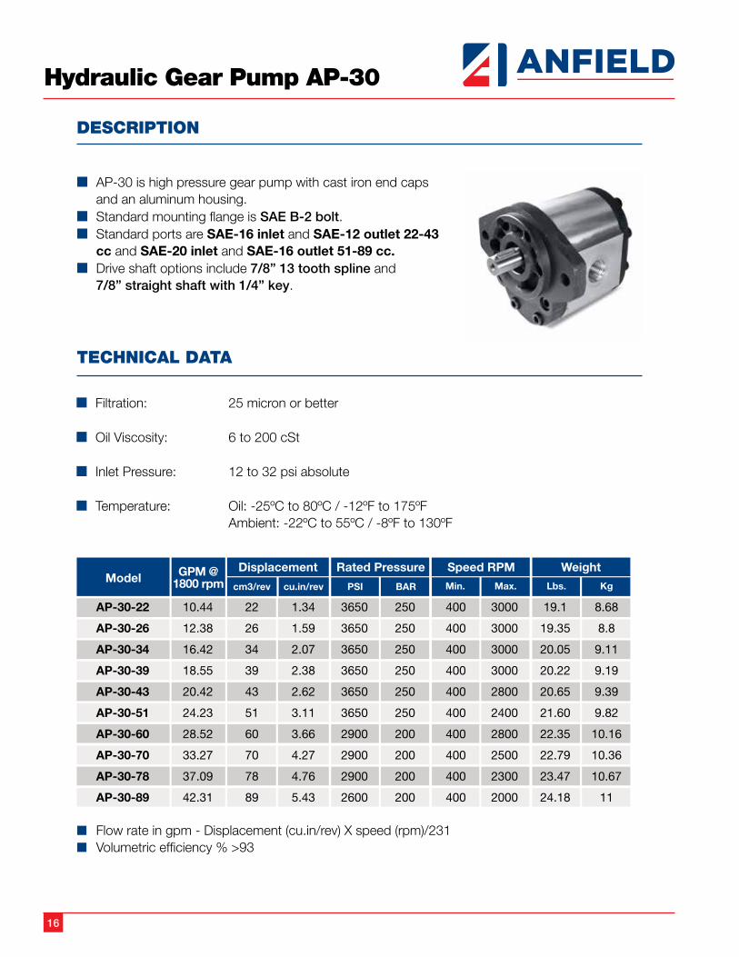
Hydraulic Gear Pump AP-30
DESCRIPTION
n AP-30 is high pressure gear pump with cast iron end caps and an aluminum housing.
n Standard mounting flange is SAE B-2 bolt. n Standard ports are SAE-16 inlet and SAE-12 outlet 22-43
cc and SAE-20 inlet and SAE-16 outlet 51-89 cc.n Drive shaft options include 7/8” 13 tooth spline and
7/8” straight shaft with 1/4” key.
TECHNICAL DATA
n Filtration: 25 micron or better
n Oil Viscosity: 6 to 200 cSt
n Inlet Pressure: 12 to 32 psi absolute
n Temperature: Oil: -25ºC to 80ºC / -12ºF to 175ºF Ambient: -22ºC to 55ºC / -8ºF to 130ºF
n Flow rate in gpm - Displacement (cu.in/rev) X speed (rpm)/231n Volumetric efficiency % >93
17
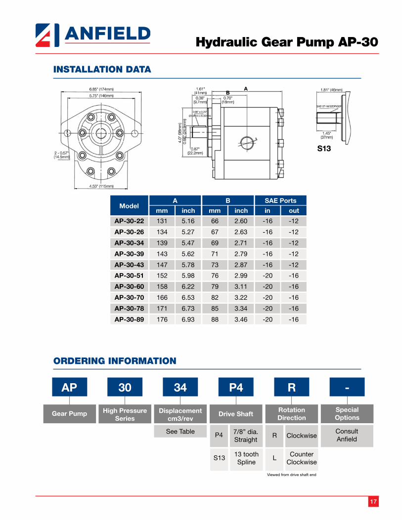
Hydraulic Gear Pump AP-30
INSTALLATION DATA
ORDERING INFORMATION

18
Hydraulic Gear Pump AP-HL
DESCRIPTION
n AP-HL is a HI/LO cast iron Hydraulic Gear Pump with a max pressure of 900 psi for the low pressure pump and 3000 psi for the high pressure pump. The change from LO to HI pressure is automatic with the LO side pressure pre set from 400 psi to 900 psi. The HI/LO section of the pump and the end plates are cast iron. Applications for the HI/LO pump are log splitters, presses etc. where rapid movement of the cylinder at low pressure is required prior to automatically switching to the high pressure mode to meet load requirements.
TECHNICAL DATA
n Filtration: 25 micron or better
n Oil Viscosity: 6 to 200 cSt
n Inlet Pressure: 12 to 32 psi absolute
n Temperature: Oil: -25ºC to 80ºC / -12ºF to 175ºF Ambient: -22ºC to 55ºC / -8ºF to 130ºF
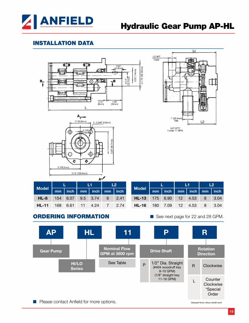
n Port Sizes: Inlet: 3/4” NPTF (8-10 GPM) 1” pipe (11-16 GPM) Outlet: 1/2” NPT Different port options available upon request
n Shaft: 1/2 straight shaft with #404 woodruff key (8-10GPM)
n More displacements available upon request.
19
Hydraulic Gear Pump AP-HL
INSTALLATION DATA
ORDERING INFORMATION
n Please contact Anfield for more options.
nSee next page for 22 and 28 GPM.
20
Hydraulic Gear Pump AP-HFL
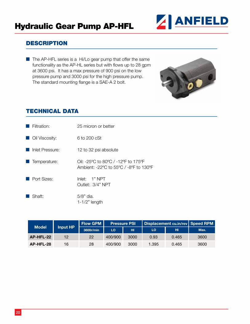
DESCRIPTION
n The AP-HFL series is a Hi/Lo gear pump that offer the same functionality as the AP-HL series but with flows up to 28 gpm at 3600 psi. It has a max pressure of 900 psi on the low pressure pump and 3000 psi for the high pressure pump. The standard mounting flange is a SAE-A 2 bolt.
TECHNICAL DATA
n Filtration: 25 micron or better
n Oil Viscosity: 6 to 200 cSt
n Inlet Pressure: 12 to 32 psi absolute
n Temperature: Oil: -25ºC to 80ºC / -12ºF to 175ºF Ambient: -22ºC to 55ºC / -8ºF to 130ºF
n Port Sizes: Inlet: 1” NPT Outlet: 3/4” NPT
n Shaft: 5/8” dia. 1-1/2” length
21
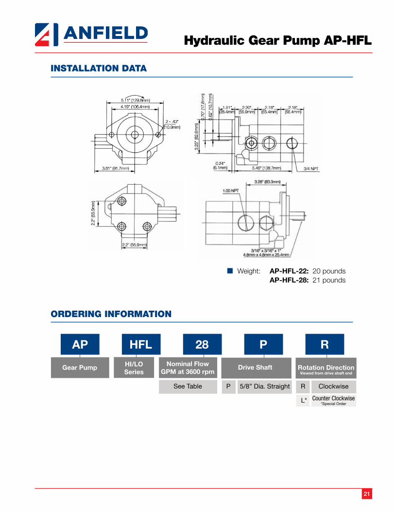
Hydraulic Gear Pump AP-HFL
ORDERING INFORMATION
INSTALLATION DATA
n Weight: AP-HFL-22: 20 pounds AP-HFL-28: 21 pounds
22
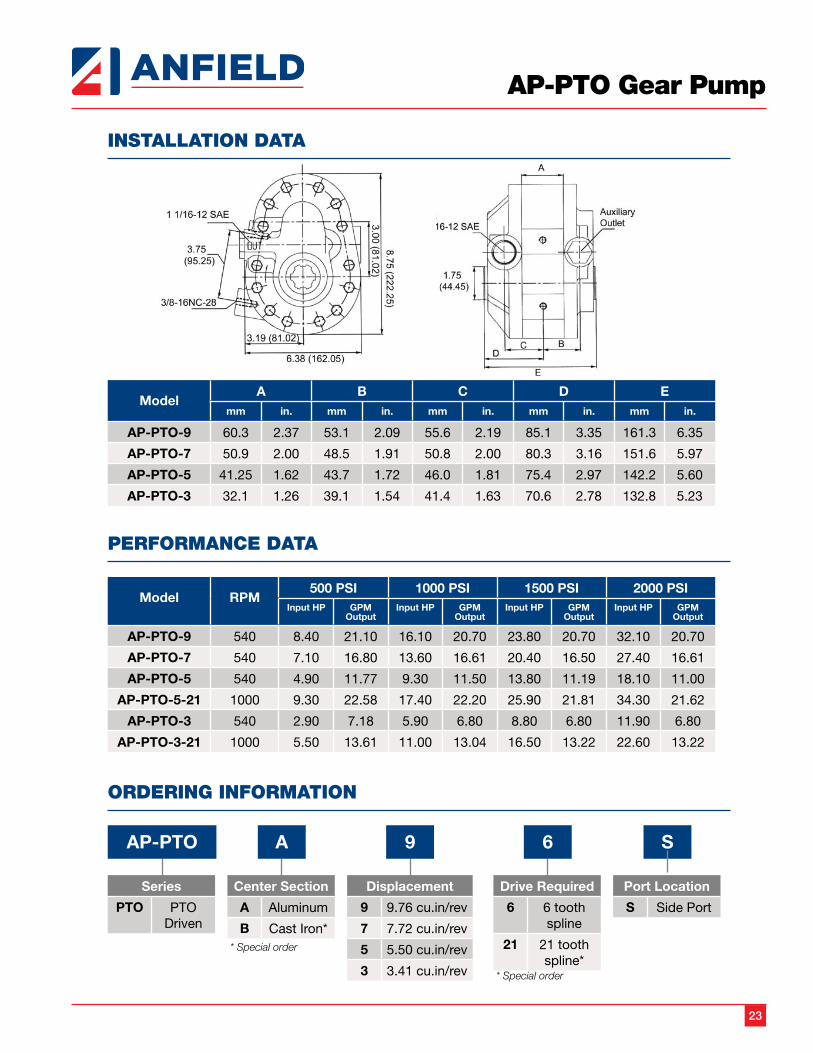
AP-PTO Gear Pump
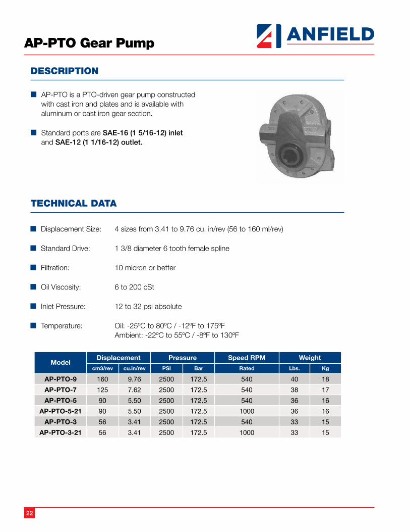
DESCRIPTION
n AP-PTO is a PTO-driven gear pump constructed with cast iron and plates and is available with aluminum or cast iron gear section.
n Standard ports are SAE-16 (1 5/16-12) inlet and SAE-12 (1 1/16-12) outlet.
TECHNICAL DATA
n Displacement Size: 4 sizes from 3.41 to 9.76 cu. in/rev (56 to 160 ml/rev)
n Standard Drive: 1 3/8 diameter 6 tooth female spline
n Filtration: 10 micron or better
n Oil Viscosity: 6 to 200 cSt
n Inlet Pressure: 12 to 32 psi absolute
n Temperature: Oil: -25ºC to 80ºC / -12ºF to 175ºF Ambient: -22ºC to 55ºC / -8ºF to 130ºF
ModelDisplacement Pressure Speed RPM Weight
cm3/rev cu.in/rev PSI Bar Rated Lbs. Kg
AP-PTO-9 160 9.76 2500 172.5 540 40 18
AP-PTO-7 125 7.62 2500 172.5 540 38 17
AP-PTO-5 90 5.50 2500 172.5 540 36 16
AP-PTO-5-21 90 5.50 2500 172.5 1000 36 16
AP-PTO-3 56 3.41 2500 172.5 540 33 15
AP-PTO-3-21 56 3.41 2500 172.5 1000 33 15
23
INSTALLATION DATA
AP-PTO Gear Pump
ModelA B C D E
mm in. mm in. mm in. mm in. mm in.
AP-PTO-9 60.3 2.37 53.1 2.09 55.6 2.19 85.1 3.35 161.3 6.35
AP-PTO-7 50.9 2.00 48.5 1.91 50.8 2.00 80.3 3.16 151.6 5.97
AP-PTO-5 41.25 1.62 43.7 1.72 46.0 1.81 75.4 2.97 142.2 5.60
AP-PTO-3 32.1 1.26 39.1 1.54 41.4 1.63 70.6 2.78 132.8 5.23
PERFORMANCE DATA
Model RPM500 PSI 1000 PSI 1500 PSI 2000 PSI
Input HP GPM Output
Input HP GPM Output
Input HP GPM Output
Input HP GPM Output
AP-PTO-9 540 8.40 21.10 16.10 20.70 23.80 20.70 32.10 20.70
AP-PTO-7 540 7.10 16.80 13.60 16.61 20.40 16.50 27.40 16.61
AP-PTO-5 540 4.90 11.77 9.30 11.50 13.80 11.19 18.10 11.00
AP-PTO-5-21 1000 9.30 22.58 17.40 22.20 25.90 21.81 34.30 21.62
AP-PTO-3 540 2.90 7.18 5.90 6.80 8.80 6.80 11.90 6.80
AP-PTO-3-21 1000 5.50 13.61 11.00 13.04 16.50 13.22 22.60 13.22
ORDERING INFORMATION
AP-PTO
Series
PTO PTO Driven
A
Center Section
A Aluminum
B Cast Iron** Special order
9
Displacement
9 9.76 cu.in/rev
7 7.72 cu.in/rev
5 5.50 cu.in/rev
3 3.41 cu.in/rev
6
Drive Required
6 6 tooth spline
21 21 tooth spline*
* Special order
S
Port Location
S Side Port
24
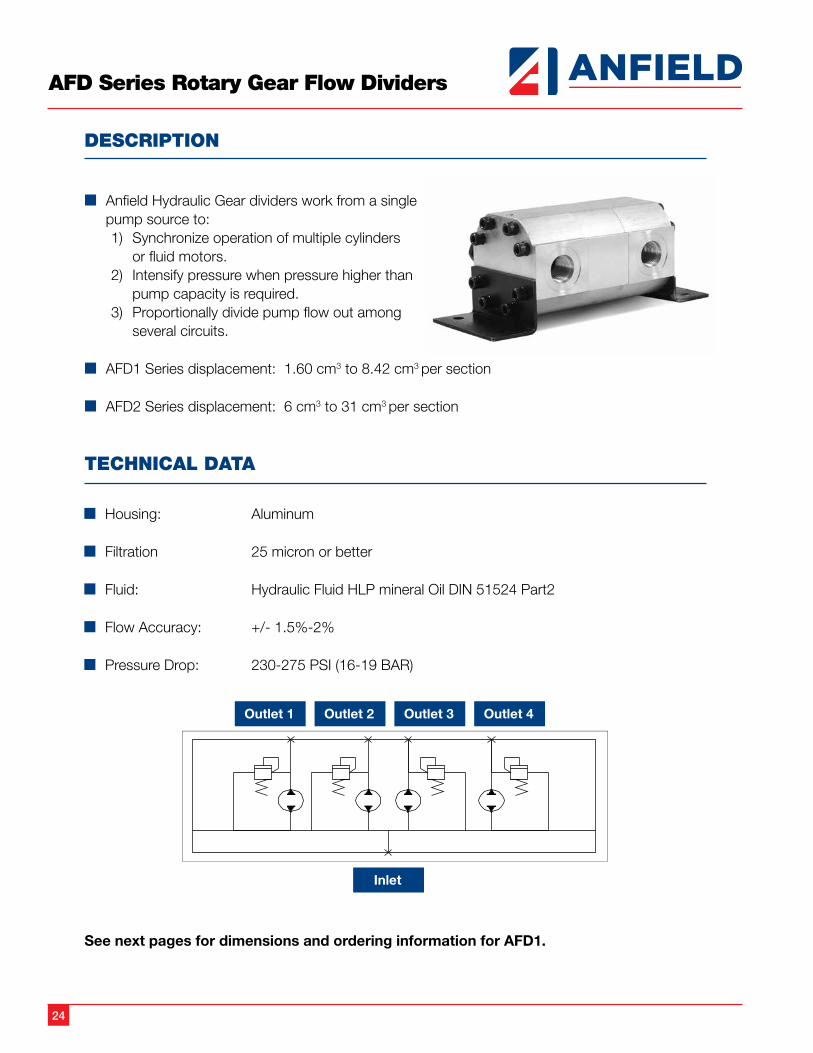
AFD Series Rotary Gear Flow Dividers
DESCRIPTION
n Anfield Hydraulic Gear dividers work from a single pump source to:1) Synchronize operation of multiple cylinders
or fluid motors.2) Intensify pressure when pressure higher than
pump capacity is required.3) Proportionally divide pump flow out among
several circuits.
n AFD1 Series displacement: 1.60 cm3 to 8.42 cm3 per section
n AFD2 Series displacement: 6 cm3 to 31 cm3 per section
TECHNICAL DATA
n Housing: Aluminum
n Filtration 25 micron or better
n Fluid: Hydraulic Fluid HLP mineral Oil DIN 51524 Part2
n Flow Accuracy: +/- 1.5%-2%
n Pressure Drop: 230-275 PSI (16-19 BAR)
See next pages for dimensions and ordering information for AFD1.
25
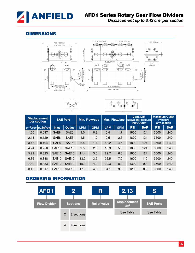
AFD1 Series Rotary Gear Flow DividersDisplacement up to 8.42 cm3 per section
DIMENSIONS
ORDERING INFORMATION
7.85" (199.5mm)
5.67" (144mm)
3.68" (93.5mm) 3.68" (93.5mm)
1.67"(42.5mm)
2.01"(51mm)
2.01"(51mm)
1.5"(38mm)
1.67"(42.5mm)
1.38" (35mm)
3.92" (99.6mm)
3.15"(80mm)
3.11
" (7
9mm
)3.
15"
(80m
m)
2.19
"(5
5.6m
m)
3.15
" (8
0mm
)
2.19
"(5
5.6m
m)
3.46" (88mm)4.76" (121mm)6.54" (166mm)
4 - ø1.38"(35mm)
4 - ø1.38"(35mm)
10.62" (269.8mm)
11.85" (301mm)
4 - ø0.31"(8mm)
26
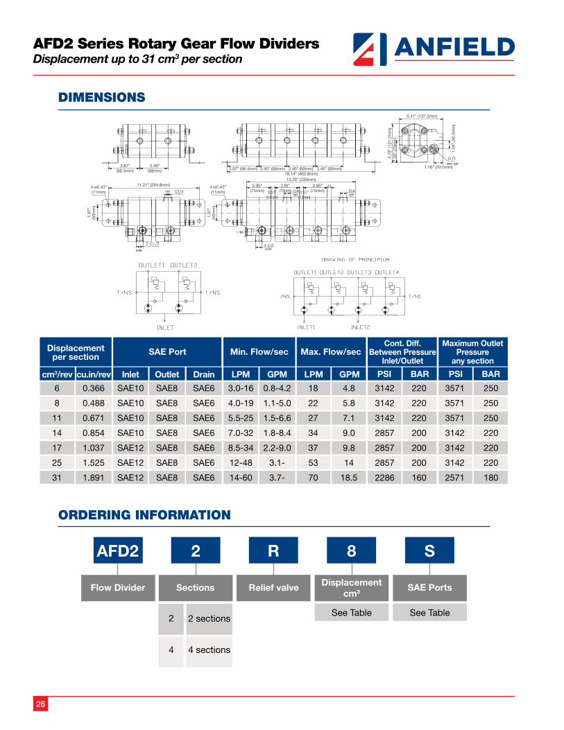
AFD2 Series Rotary Gear Flow DividersDisplacement up to 31 cm3 per section
DIMENSIONS
ORDERING INFORMATION

USAAnfield Industries Inc.375 International Park, Suite 300 Newnan, Georgia 30265Phone: (404) 530-3804Fax: (404) 530-3805Email: [email protected]: www.anfieldindustries.com
CanadaMP Filtri Canada, Inc.8831 Keele StreetConcord, OntarioL4K 2N1, CanadaPhone: (905) 303-1369Fax: (905) 303-7256Email: [email protected]: www.mpfiltricanada.com
Gear Pumps Catalog2017 R0517
Strength in Products, Strength in Service
n Pressure Switches
n Temperature Switches
n Transducers
n Gear Pumps
n Flow Dividers
n Hydraulic Motors
n Jaw Couplings
n High Pressure Ball Valves
n Flow Control and Needle Valves
n Test Points
n Gauges
n Monoblock Valves
n Sectional Valves