gear pumps group 0 and group 1 - danfoss · 2020-01-31 · skp1nn 06sa snp1nn 03ca features and...
TRANSCRIPT
Revision history Table of revisions
Date Changed Rev
October 2019 First edition 0101
Technical InformationGear Pumps Group 0 and Group 1 Technical Information
2 | © Danfoss | October 2019 BC320173499791en-000101
General InformationOverview..............................................................................................................................................................................................5Features and benefits..................................................................................................................................................................... 6
Group 0Design...................................................................................................................................................................................................7Features................................................................................................................................................................................................7Product Code..................................................................................................................................................................................... 8
Model code....................................................................................................................................................................................8A Family.....................................................................................................................................................................................8B Displacement.......................................................................................................................................................................8C Rotation................................................................................................................................................................................. 9D Project version....................................................................................................................................................................9E Mounting flange................................................................................................................................................................. 9F Drive gear.............................................................................................................................................................................. 9G Rear cover.............................................................................................................................................................................9H Inlet size; I Outlet size.......................................................................................................................................................9J Ports positions & Special body.................................................................................................................................... 10K Seals......................................................................................................................................................................................10L Screws.................................................................................................................................................................................. 10M Set valve.............................................................................................................................................................................10N Type mark.......................................................................................................................................................................... 10O Mark position....................................................................................................................................................................10
Dimensions.......................................................................................................................................................................................11TFPONN-01FA............................................................................................................................................................................ 11
Group 1Pump design....................................................................................................................................................................................12SNP1NN............................................................................................................................................................................................. 12SKP1NN..............................................................................................................................................................................................13SKP1IN................................................................................................................................................................................................13Pump displacements.................................................................................................................................................................... 14
General InformationTechnical data................................................................................................................................................................................. 15
Product CodeModel code.......................................................................................................................................................................................17
A Family........................................................................................................................................................................................17B Displacement..........................................................................................................................................................................17C Rotation....................................................................................................................................................................................17D Project version.......................................................................................................................................................................17E Mounting flange....................................................................................................................................................................18F Drive gear.................................................................................................................................................................................18G Rear cover................................................................................................................................................................................18H Inlet size; I Outlet size..........................................................................................................................................................18J Ports positions & Special body..........................................................................................................................................19K Seals........................................................................................................................................................................................... 19L Screws........................................................................................................................................................................................20M Set valve.................................................................................................................................................................................. 20N Type mark................................................................................................................................................................................20O Mark position......................................................................................................................................................................... 20
Determination of Nominal Pump SizesDetermination of nominal pump sizes.................................................................................................................................. 21
System RequirementsPressure............................................................................................................................................................................................. 22Speed..................................................................................................................................................................................................22Hydraulic fluids............................................................................................................................................................................... 23Temperature and viscosity......................................................................................................................................................... 23Filtration............................................................................................................................................................................................ 24
Technical InformationGear Pumps Group 0 and Group 1 Technical Information
Contents
© Danfoss | October 2019 BC320173499791en-000101 | 3
Filters.............................................................................................................................................................................................24Selecting a filter.........................................................................................................................................................................24Reservoir...................................................................................................................................................................................... 24
Line sizing......................................................................................................................................................................................... 25Pump drive....................................................................................................................................................................................... 25Pump drive data form.................................................................................................................................................................. 26Pump Life.......................................................................................................................................................................................... 27Sound levels.....................................................................................................................................................................................27
Pump PerformancePump performance graphs........................................................................................................................................................ 28
Product OptionsFlange, shaft and port configurations.................................................................................................................................... 31Shaft options....................................................................................................................................................................................32Inlet/Outlet port configurations............................................................................................................................................... 33Ports.................................................................................................................................................................................................... 33SNP1IN............................................................................................................................................................................................... 34Variant codes for ordering integral relief valves.................................................................................................................35Integral relief valve schematic...................................................................................................................................................37
DimensionsSNP1NN - 01BA and 01DA.......................................................................................................................................................... 38SKP1NN – 02BB and 02FA........................................................................................................................................................... 39SNP1NN – 03CA.............................................................................................................................................................................. 40SKP1NN – 06GA and 06SA.......................................................................................................................................................... 41
Technical InformationGear Pumps Group 0 and Group 1 Technical Information
Contents
4 | © Danfoss | October 2019 BC320173499791en-000101
Overview
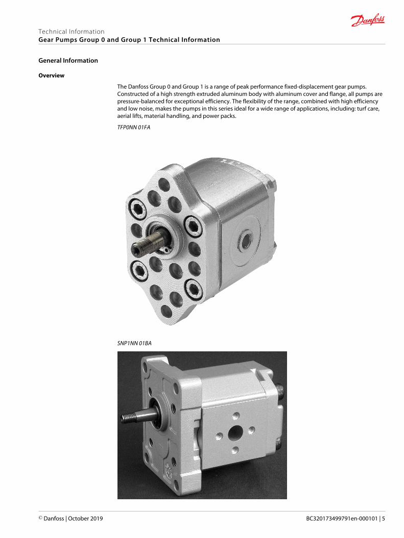
The Danfoss Group 0 and Group 1 is a range of peak performance fixed-displacement gear pumps.Constructed of a high strength extruded aluminum body with aluminum cover and flange, all pumps arepressure-balanced for exceptional efficiency. The flexibility of the range, combined with high efficiencyand low noise, makes the pumps in this series ideal for a wide range of applications, including: turf care,aerial lifts, material handling, and power packs.
TFP0NN 01FA
SNP1NN 01BA
Technical InformationGear Pumps Group 0 and Group 1 Technical Information
General Information
© Danfoss | October 2019 BC320173499791en-000101 | 5

SKP1NN 06SA
SNP1NN 03CA
Features and benefits
Gear pump attributes:
• Up to 16 displacements from 0,25 to 12 cm3/rev [from 0.015 to 0.732 in3/rev• Continuous pressure rating up to 250 bar [3625 psi]• Speeds up to 4000 min-1 (rpm)• SAE, ISO, and DIN mounting flanges and shafts• Compact, lightweight, quiet operation• Group 1 units are available as unidirectional and bi-directional motors, also with integral relief valve• You can combine groups 1, 2 and 3 to make multi-stage pump
Technical InformationGear Pumps Group 0 and Group 1 Technical Information
General Information
6 | © Danfoss | October 2019 BC320173499791en-000101
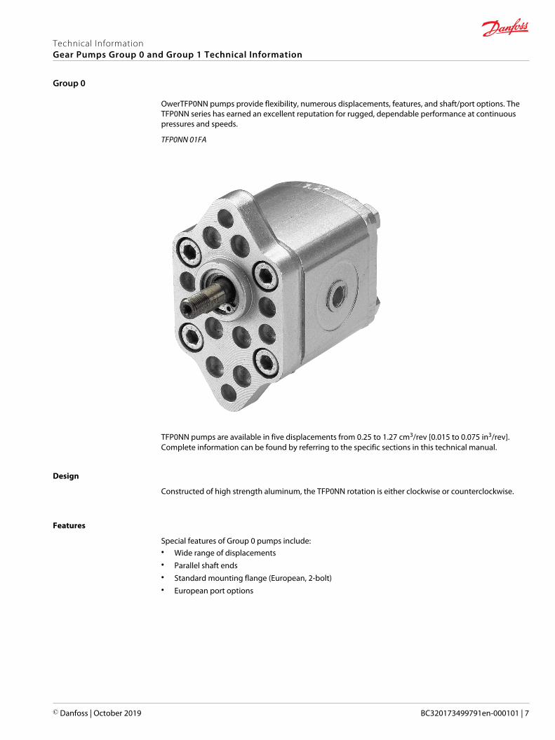
OwerTFP0NN pumps provide flexibility, numerous displacements, features, and shaft/port options. TheTFP0NN series has earned an excellent reputation for rugged, dependable performance at continuouspressures and speeds.
TFP0NN 01FA
TFP0NN pumps are available in five displacements from 0.25 to 1.27 cm3/rev [0.015 to 0.075 in3/rev].Complete information can be found by referring to the specific sections in this technical manual.
Design
Constructed of high strength aluminum, the TFP0NN rotation is either clockwise or counterclockwise.
Features
Special features of Group 0 pumps include:• Wide range of displacements• Parallel shaft ends• Standard mounting flange (European, 2-bolt)• European port options
Technical InformationGear Pumps Group 0 and Group 1 Technical Information
Group 0
© Danfoss | October 2019 BC320173499791en-000101 | 7
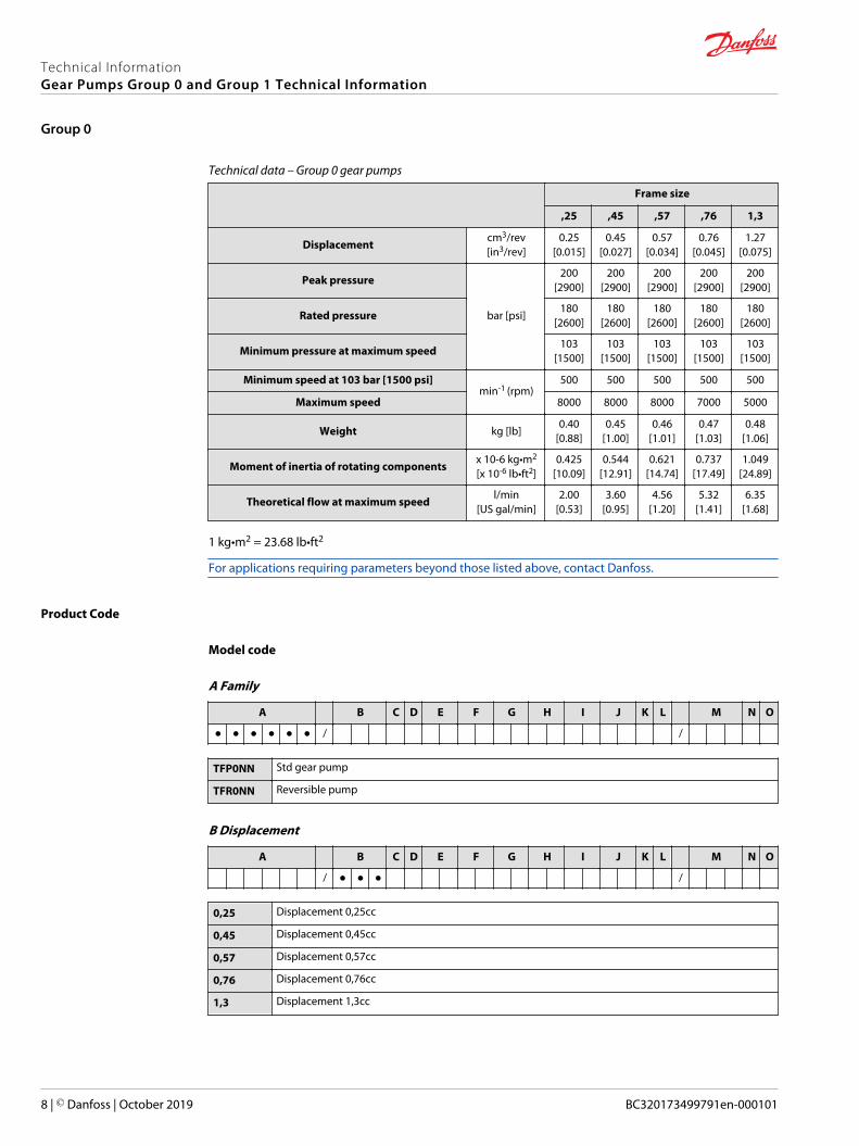
Technical data – Group 0 gear pumps
Frame size
,25 ,45 ,57 ,76 1,3
Displacementcm3/rev[in3/rev]
0.25[0.015]
0.45[0.027]
0.57[0.034]
0.76[0.045]
1.27[0.075]
Peak pressure
bar [psi]
200[2900]
200[2900]
200[2900]
200[2900]
200[2900]
Rated pressure180
[2600]180
[2600]180
[2600]180
[2600]180
[2600]
Minimum pressure at maximum speed103
[1500]103
[1500]103
[1500]103
[1500]103
[1500]
Minimum speed at 103 bar [1500 psi]min-1 (rpm)
500 500 500 500 500
Maximum speed 8000 8000 8000 7000 5000
Weight kg [lb]0.40
[0.88]0.45
[1.00]0.46
[1.01]0.47
[1.03]0.48
[1.06]
Moment of inertia of rotating componentsx 10-6 kg•m2
[x 10-6 lb•ft2]0.425
[10.09]0.544
[12.91]0.621
[14.74]0.737
[17.49]1.049
[24.89]
Theoretical flow at maximum speedl/min
[US gal/min]2.00
[0.53]3.60
[0.95]4.56
[1.20]5.32
[1.41]6.35
[1.68]
1 kg•m2 = 23.68 lb•ft2
For applications requiring parameters beyond those listed above, contact Danfoss.
Product Code
Model code
A Family
A B C D E F G H I J K L M N O
● ● ● ● ● ● / /
TFP0NN Std gear pump
TFR0NN Reversible pump
B Displacement
A B C D E F G H I J K L M N O
/ ● ● ● /
0,25 Displacement 0,25cc
0,45 Displacement 0,45cc
0,57 Displacement 0,57cc
0,76 Displacement 0,76cc
1,3 Displacement 1,3cc
Technical InformationGear Pumps Group 0 and Group 1 Technical Information
Group 0
8 | © Danfoss | October 2019 BC320173499791en-000101

C Rotation
A B C D E F G H I J K L M N O
/ ● /
L Left rotation
R Right rotation
B Reversible pump
D Project version
A B C D E F G H I J K L M N O
/ ● /
N Std gear version
E Mounting flange
A B C D E F G H I J K L M N O
/ ● ● /
Code Description (Type of flange • Type of drive gear • Preferred ports for configuration)
01 European 2-bolt flange
F Drive gear
A B C D E F G H I J K L M N O
/ ● ● /
CA Tang drive 5xØ7
FA Parallel shaft 7,0 mm [0.276 in]
G Rear cover
A B C D E F G H I J K L M N O
/ ● ● /
P1 Standard cover for pump
P3 Standard cover for reversible pump
H Inlet size; I Outlet size
A B C D E F G H I J K L M N O
/ ● ● ● ● /
Technical InformationGear Pumps Group 0 and Group 1 Technical Information
Group 0
© Danfoss | October 2019 BC320173499791en-000101 | 9
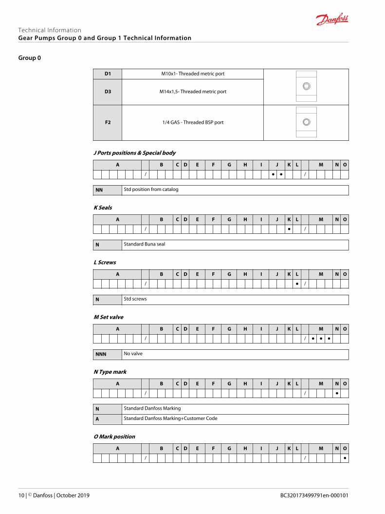
D1 M10x1- Threaded metric port
D3 M14x1,5- Threaded metric port
F2 1/4 GAS - Threaded BSP port
J Ports positions & Special body
A B C D E F G H I J K L M N O
/ ● ● /
NN Std position from catalog
K Seals
A B C D E F G H I J K L M N O
/ ● /
N Standard Buna seal
L Screws
A B C D E F G H I J K L M N O
/ ● /
N Std screws
M Set valve
A B C D E F G H I J K L M N O
/ / ● ● ●
NNN No valve
N Type mark
A B C D E F G H I J K L M N O
/ / ●
N Standard Danfoss Marking
A Standard Danfoss Marking+Customer Code
O Mark position
A B C D E F G H I J K L M N O
/ / ●
Technical InformationGear Pumps Group 0 and Group 1 Technical Information
Group 0
10 | © Danfoss | October 2019 BC320173499791en-000101

N Std Marking position (on top)
A Special Marking position on the bottom
Dimensions
TFPONN-01FA
Available 01FA configuration only.
TFP0NN dimensions
Frame size ,25 ,45 ,57 ,76 1,3
DimensionA 53.5 [2.10] 55.0 [2.16] 56.0 [2.20] 61.5 [2.42] 61.5 [2.42]
B 26.5 [1.04] 27.3 [1.07] 27.8 [1.09] 30.5 [1.20] 30.5 [1.20]
Inlet/Outlet M10 x 1
Model code examples and maximum shaft torque
Flange/drive gear Model code example Maximum shaft torque
01FA TFP0NN/,57RN01FAP1D1D1NNNN/NNNNN 4.5 N•m [39.8 lb•in]
For further details on ordering, see Product Code on page 8.
Technical InformationGear Pumps Group 0 and Group 1 Technical Information
Group 0
© Danfoss | October 2019 BC320173499791en-000101 | 11

Pump design
SNP1NN
SNP1NN pumps only include European flange and shaft configurations (code 01BA, 01DA, and 03CA).
SNP1NN 01BA (cut away)
Technical InformationGear Pumps Group 0 and Group 1 Technical Information
Group 1
12 | © Danfoss | October 2019 BC320173499791en-000101
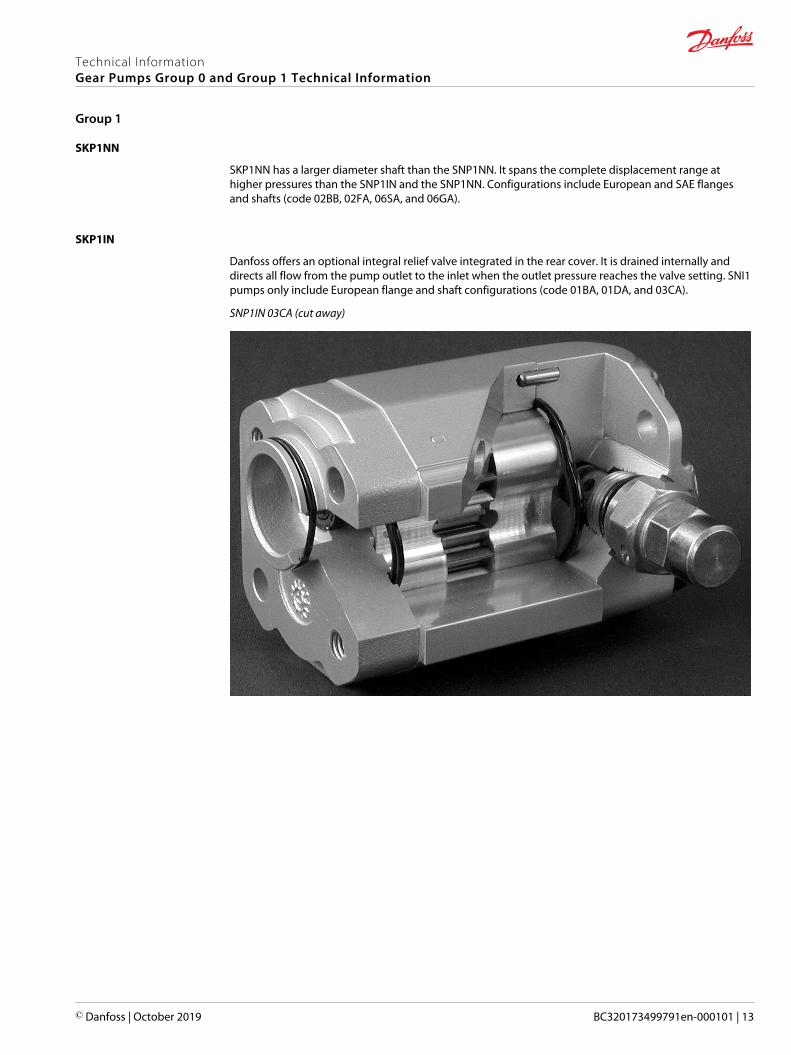
SKP1NN
SKP1NN has a larger diameter shaft than the SNP1NN. It spans the complete displacement range athigher pressures than the SNP1IN and the SNP1NN. Configurations include European and SAE flangesand shafts (code 02BB, 02FA, 06SA, and 06GA).
SKP1IN
Danfoss offers an optional integral relief valve integrated in the rear cover. It is drained internally anddirects all flow from the pump outlet to the inlet when the outlet pressure reaches the valve setting. SNI1pumps only include European flange and shaft configurations (code 01BA, 01DA, and 03CA).
SNP1IN 03CA (cut away)
Technical InformationGear Pumps Group 0 and Group 1 Technical Information
Group 1
© Danfoss | October 2019 BC320173499791en-000101 | 13
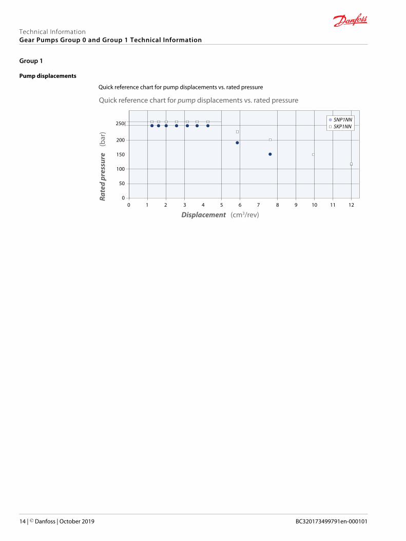
Pump displacements
Quick reference chart for pump displacements vs. rated pressure
Quick reference chart for pump displacements vs. rated pressure
Displacement (cm3/rev)
Rate
d pr
essu
re
(bar
)
200
150
100
50
0
250{
0 1 2 3 4 5 6 7 8 9 10 11 12
SNP1NNSKP1NN
Technical InformationGear Pumps Group 0 and Group 1 Technical Information
Group 1
14 | © Danfoss | October 2019 BC320173499791en-000101
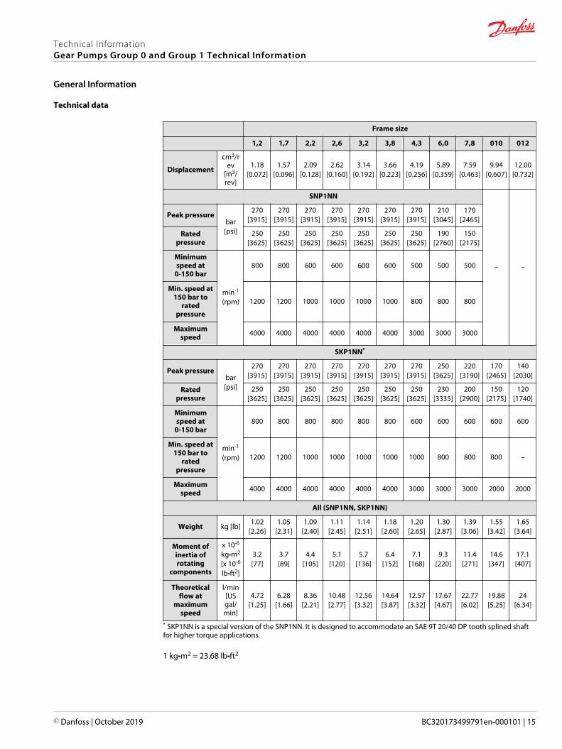
Technical data
Frame size
1,2 1,7 2,2 2,6 3,2 3,8 4,3 6,0 7,8 010 012
Displacement
cm3/rev
[in3/rev]
1.18[0.072]
1.57[0.096]
2.09[0.128]
2.62[0.160]
3.14[0.192]
3.66[0.223]
4.19[0.256]
5.89[0.359]
7.59[0.463]
9.94[0.607]
12.00[0.732]
SNP1NN
– –
Peak pressurebar[psi]
270[3915]
270[3915]
270[3915]
270[3915]
270[3915]
270[3915]
270[3915]
210[3045]
170[2465]
Ratedpressure
250[3625]
250[3625]
250[3625]
250[3625]
250[3625]
250[3625]
250[3625]
190[2760]
150[2175]
Minimumspeed at
0-150 bar
min-1
(rpm)
800 800 600 600 600 600 500 500 500
Min. speed at150 bar to
ratedpressure
1200 1200 1000 1000 1000 1000 800 800 800
Maximumspeed 4000 4000 4000 4000 4000 4000 3000 3000 3000
SKP1NN*
Peak pressurebar[psi]
270[3915]
270[3915]
270[3915]
270[3915]
270[3915]
270[3915]
270[3915]
250[3625]
220[3190]
170[2465]
140[2030]
Ratedpressure
250[3625]
250[3625]
250[3625]
250[3625]
250[3625]
250[3625]
250[3625]
230[3335]
200[2900]
150[2175]
120[1740]
Minimumspeed at
0-150 bar
min-1
(rpm)
800 800 800 800 800 800 600 600 600 600 600
Min. speed at150 bar to
ratedpressure
1200 1200 1000 1000 1000 1000 1000 800 800 800 –
Maximumspeed 4000 4000 4000 4000 4000 4000 3000 3000 3000 2000 2000
All (SNP1NN, SKP1NN)
Weight kg [lb]1.02
[2.26]1.05
[2.31]1.09
[2.40]1.11
[2.45]1.14
[2.51]1.18
[2.60]1.20
[2.65]1.30
[2.87]1.39
[3.06]1.55
[3.42]1.65
[3.64]
Moment ofinertia ofrotating
components
x 10-6
kg•m2
[x 10-6
lb•ft2]
3.2[77]
3.7[89]
4.4[105]
5.1[120]
5.7[136]
6.4[152]
7.1[168]
9.3[220]
11.4[271]
14.6[347]
17.1[407]
Theoreticalflow at
maximumspeed
l/min[USgal/min]
4.72[1.25]
6.28[1.66]
8.36[2.21]
10.48[2.77]
12.56[3.32]
14.64[3.87]
12.57[3.32]
17.67[4.67]
22.77[6.02]
19.88[5.25]
24[6.34]
* SKP1NN is a special version of the SNP1NN. It is designed to accommodate an SAE 9T 20/40 DP tooth splined shaftfor higher torque applications.
1 kg•m2 = 23.68 lb•ft2
Technical InformationGear Pumps Group 0 and Group 1 Technical Information
General Information
© Danfoss | October 2019 BC320173499791en-000101 | 15
C Caution
The rated and peak pressure mentioned are for pumps with flanged ports only. When threaded ports arerequired a derated performance has to be considered. To verify the compliance of an high pressureapplication with a threaded ports pump apply to a Danfoss representative.
Technical InformationGear Pumps Group 0 and Group 1 Technical Information
General Information
16 | © Danfoss | October 2019 BC320173499791en-000101
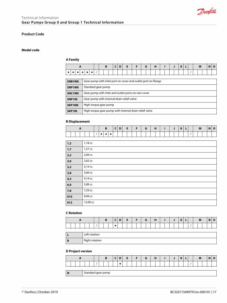
Model code
A Family
A B C D E F G H I J K L M N O
● ● ● ● ● ● / /
SNB1NN Gear pump with inlet port on cover and outlet port on flange
SNP1NN Standard gear pump
SNC1NN Gear pump with inlet and outlet ports on rear cover
SNP1IN Gear pump with internal drain relief valve
SKP1NN High torque gear pump
SKP1IN High torque gear pump with internal drain relief valve
B Displacement
A B C D E F G H I J K L M N O
/ ● ● ● /
1,2 1,18 cc
1,7 1,57 cc
2,2 2,09 cc
2,6 2,62 cc
3,2 3,14 cc
3,8 3,66 cc
4,3 4,19 cc
6,0 5,89 cc
7,8 7,59 cc
010 9,94 cc
012 12,00 cc
C Rotation
A B C D E F G H I J K L M N O
/ ● /
L Left rotation
R Right rotation
D Project version
A B C D E F G H I J K L M N O
/ ● /
N Standard gear pump
Technical InformationGear Pumps Group 0 and Group 1 Technical Information
Product Code
© Danfoss | October 2019 BC320173499791en-000101 | 17

E Mounting flange
A B C D E F G H I J K L M N O
/ ● ● /
Code Description (Type of flange • Type of drive gear • Preferred ports for configuration)
01 pilot Ø25,4+4 holes
02 pilot Ø30+4 holes
03 pilot Ø32+O-ring+2 holes through body
04 pilot Ø32+2 holes through body
06 SAE A-A pilot Ø50,8+ 2 holes
F Drive gear
A B C D E F G H I J K L M N O
/ ● ● /
AA Taper 1:5-M6-Key 2
BA Taper 1:8-M7-Key 2,41
BB Taper 1:8-M10x1-Key 3
CA Tang 5x Ø10 FR03
CE Tang 6,63x Ø11 - for SKP1xN
CM Tang 5x Ø10-type 03 + w/o coupling
DA SplinedZ15-m0,75-alfa 30°-L14 - for SNP1xx
DB SplinedZ15-m0,75-alfa 30°-L14 - for SKP1xx
FA Parallel Ø12-Thread M10x1-Key 3
GA Parallel Ø12,7-Key 3.2
G Rear cover
A B C D E F G H I J K L M N O
/ ● ● /
03 Cover 03
08 Cover 08 with Inlet port 3/8" Gas
C1 Cover pump with front GAS Thread Inlet 3/8 ; Outlet 3/8
I1 Cover pump with relief valve
I3 Cover 03 with relief valve
P1 Std Cover pump
H Inlet size; I Outlet size
A B C D E F G H I J K L M N O
/ ● ● ● ● /
Technical InformationGear Pumps Group 0 and Group 1 Technical Information
Product Code
18 | © Danfoss | October 2019 BC320173499791en-000101
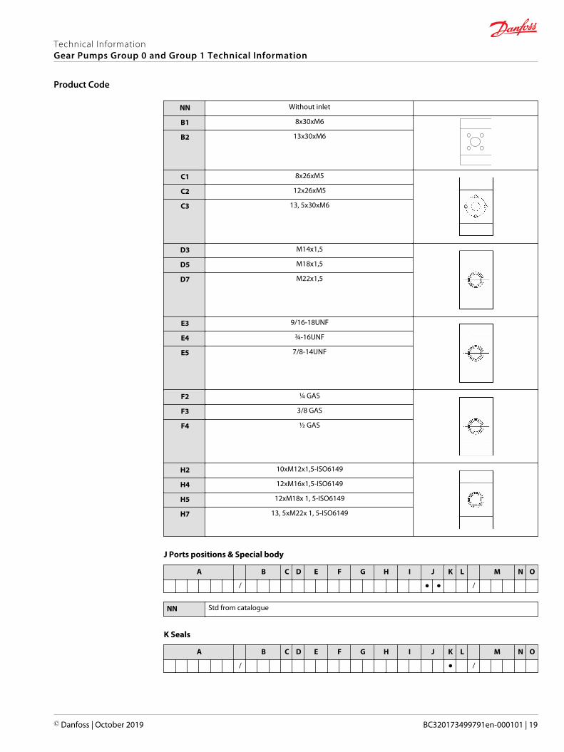
NN Without inlet
B1 8x30xM6
B2 13x30xM6
C1 8x26xM5
C2 12x26xM5
C3 13, 5x30xM6
D3 M14x1,5
D5 M18x1,5
D7 M22x1,5
E3 9/16-18UNF
E4 ¾-16UNF
E5 7/8-14UNF
F2 ¼ GAS
F3 3/8 GAS
F4 ½ GAS
H2 10xM12x1,5-ISO6149
H4 12xM16x1,5-ISO6149
H5 12xM18x 1, 5-ISO6149
H7 13, 5xM22x 1, 5-ISO6149
J Ports positions & Special body
A B C D E F G H I J K L M N O
/ ● ● /
NN Std from catalogue
K Seals
A B C D E F G H I J K L M N O
/ ● /
Technical InformationGear Pumps Group 0 and Group 1 Technical Information
Product Code
© Danfoss | October 2019 BC320173499791en-000101 | 19
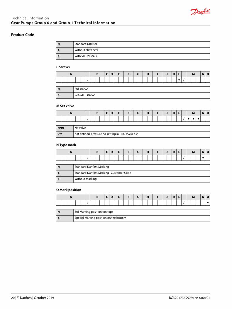
N Standard NBR seal
A Without shaft seal
B With VITON seals
L Screws
A B C D E F G H I J K L M N O
/ ● /
N Std screws
B GEOMET screws
M Set valve
A B C D E F G H I J K L M N O
/ / ● ● ●
NNN No valve
V** not defined-pressure no setting :oil ISO VG68-45°
N Type mark
A B C D E F G H I J K L M N O
/ / ●
N Standard Danfoss Marking
A Standard Danfoss Marking+Customer Code
Z Without Marking
O Mark position
A B C D E F G H I J K L M N O
/ / ●
N Std Marking position (on top)
A Special Marking position on the bottom
Technical InformationGear Pumps Group 0 and Group 1 Technical Information
Product Code
20 | © Danfoss | October 2019 BC320173499791en-000101
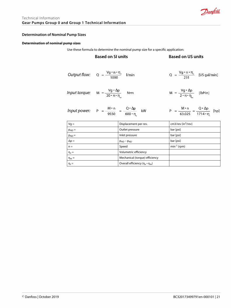
Determination of nominal pump sizes
Use these formula to determine the nominal pump size for a specific application:
Vg = Displacement per rev. cm3/rev [in3/rev]
pHD = Outlet pressure bar [psi]
pND = Inlet pressure bar [psi]
Δp = pHD – pND bar [psi]
n = Speed min-1 (rpm)
ηv = Volumetric efficiency
ηm = Mechanical (torque) efficiency
ηt = Overall efficiency (ηv • ηm)
Technical InformationGear Pumps Group 0 and Group 1 Technical Information
Determination of Nominal Pump Sizes
© Danfoss | October 2019 BC320173499791en-000101 | 21

Pressure
The inlet vacuum must be controlled in order to realize expected pump life and performance. The systemdesign must meet inlet pressure requirements during all modes of operation. Expect lower inletpressures during cold start. It should improve quickly as the fluid warms.
Max. continuous vacuum bar abs. [in. Hg] 0.8 [23.6]
Max. intermittent vacuum 0.6 [17.7]
Max. pressure 3.0 [88.5]
Peak pressure is the highest intermittent pressure allowed. The relief valve overshoot (reaction time)determines peak pressure. It is assumed to occur for less than 100 ms. The accompanying illustrationshows peak pressure in relation to rated pressure and reaction time (100 ms maximum).
Peak pressure
Rated pressure
Reaction time (100 ms max)
Time
Pres
sure
Rated pressure is the average, regularly occurring, operating pressure that should yield satisfactoryproduct life. The maximum machine load demand determines rated pressure. For all systems, the loadshould move below this pressure.
System pressure is the differential of pressure between the outlet and inlet ports. It is a dominantoperating variable affecting hydraulic unit life. High system pressure, resulting from high load, reducesexpected life. System pressure must remain at, or below, rated pressure during normal operation toachieve expected life.
Speed
Maximum speed is the limit recommended by Danfoss for a particular gear pump when operating atrated pressure. It is the highest speed at which normal life can be expected.
The lower limit of operating speed is the minimum speed. It is the lowest speed at which normal life canbe expected. The minimum speed increases as operating pressure increases. When operating underhigher pressures, a higher minimum speed must be maintained, as illustrated here.
Technical InformationGear Pumps Group 0 and Group 1 Technical Information
System Requirements
22 | © Danfoss | October 2019 BC320173499791en-000101

Speed versus pressure
Rated
P1
Pres
sure
0N MaxN2
Speed
Operatingenvelope
1
Where:
N1 = Minimum speed at 100 bar
N2 = Minimum speed at 180 bar
Hydraulic fluids
Ratings and data for SNP1NN, and SKP1NN gear pumps are based on operating with premium hydraulicfluids containing oxidation, rust, and foam inhibitors. These fluids must possess good thermal andhydrolytic stability to prevent wear, erosion, and corrosion of internal components. They include:• Hydraulic fluids following DIN 51524, part 2 (HLP) and part 3 (HVLP) specifications• API CD engine oils conforming to SAE J183• M2C33F or G automatic transmission fluids• Certain agricultural tractor fluids
Use only clean fluid in the pump and hydraulic circuit.
C Caution
Never mix hydraulic fluids.
Temperature and viscosity
Temperature and viscosity requirements must be concurrently satisfied. Use petroleum / mineral-based fluids.
High temperature limits apply at the inlet port to the pump. The pump should run at or below themaximum continuous temperature. The peak temperature is based on material properties. Don’t exceedit.
Cold oil, generally, doesn’t affect the durability of pump components. It may affect the ability of oil toflow and transmit power. For this reason, keep the temperature at 16 °C [60 °F] above the pour point ofthe hydraulic fluid.
Minimum (cold start) temperature relates to the physical properties of component materials.
Minimum viscosity occurs only during brief occasions of maximum ambient temperature and severe dutycycle operation. You will encounter maximum viscosity only at cold start. During this condition, limitspeeds until the system warms up. Size heat exchangers to keep the fluid within these limits. Testregularly to verify that these temperatures and viscosity limits aren’t exceeded. For maximum unitefficiency and bearing life, keep the fluid viscosity in the recommended viscosity range.
Technical InformationGear Pumps Group 0 and Group 1 Technical Information
System Requirements
© Danfoss | October 2019 BC320173499791en-000101 | 23
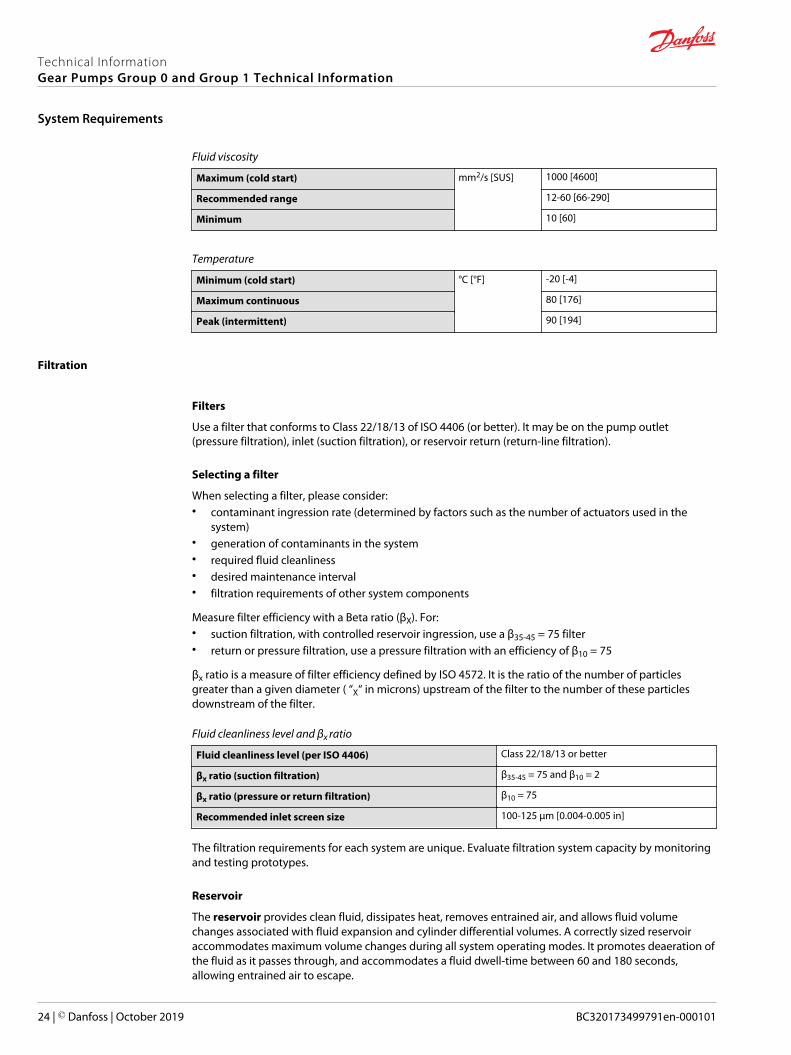
Fluid viscosity
Maximum (cold start) mm2/s [SUS] 1000 [4600]
Recommended range 12-60 [66-290]
Minimum 10 [60]
Temperature
Minimum (cold start) °C [°F] -20 [-4]
Maximum continuous 80 [176]
Peak (intermittent) 90 [194]
Filtration
Filters
Use a filter that conforms to Class 22/18/13 of ISO 4406 (or better). It may be on the pump outlet(pressure filtration), inlet (suction filtration), or reservoir return (return-line filtration).
Selecting a filter
When selecting a filter, please consider:• contaminant ingression rate (determined by factors such as the number of actuators used in the
system)• generation of contaminants in the system• required fluid cleanliness• desired maintenance interval• filtration requirements of other system components
Measure filter efficiency with a Beta ratio (βX). For:• suction filtration, with controlled reservoir ingression, use a β35-45 = 75 filter• return or pressure filtration, use a pressure filtration with an efficiency of β10 = 75
βx ratio is a measure of filter efficiency defined by ISO 4572. It is the ratio of the number of particlesgreater than a given diameter ( “X“ in microns) upstream of the filter to the number of these particlesdownstream of the filter.
Fluid cleanliness level and βx ratio
Fluid cleanliness level (per ISO 4406) Class 22/18/13 or better
βx ratio (suction filtration) β35-45 = 75 and β10 = 2
βx ratio (pressure or return filtration) β10 = 75
Recommended inlet screen size 100-125 µm [0.004-0.005 in]
The filtration requirements for each system are unique. Evaluate filtration system capacity by monitoringand testing prototypes.
Reservoir
The reservoir provides clean fluid, dissipates heat, removes entrained air, and allows fluid volumechanges associated with fluid expansion and cylinder differential volumes. A correctly sized reservoiraccommodates maximum volume changes during all system operating modes. It promotes deaeration ofthe fluid as it passes through, and accommodates a fluid dwell-time between 60 and 180 seconds,allowing entrained air to escape.
Technical InformationGear Pumps Group 0 and Group 1 Technical Information
System Requirements
24 | © Danfoss | October 2019 BC320173499791en-000101

Minimum reservoir capacity depends on the volume required to cool and hold the oil from all retractedcylinders, allowing for expansion due to temperature changes. A fluid volume of 1 to 3 times the pumpoutput flow (per minute) is satisfactory. The minimum reservoir capacity is 125% of the fluid volume.
Install the suction line above the bottom of the reservoir to take advantage of gravity separation andprevent large foreign particles from entering the line. Cover the line with a 100-125 micron screen. Thepump should be below the lowest expected fluid level. Put the return-line below the lowest expectedfluid level to allow discharge into the reservoir for maximum dwell and efficient deaeration. A baffle (orbaffles) between the return and suction lines promotes deaeration and reduces fluid surges.
Line sizing
Choose pipe sizes that accommodate minimum fluid velocity to reduce system noise, pressure drops, andoverheating. This maximizes system life and performance.
Design inlet piping that maintains continuous pump inlet pressure above 0.8 bar absolute during normaloperation. The line velocity should not exceed the values in this table:
Maximum line velocity
Inlet
m/s [ft/sec]
2.5 [8.2]
Outlet 5.0 [16.4]
Return 3.0 [9.8]
Most systems use hydraulic oil containing 10% dissolved air by volume. Under high inlet vacuumconditions the oil releases bubbles. They collapse when subjected to pressure, resulting in cavitation,causing adjacent metal surfaces to erode. Over-aeration is the result of air leaks on the inlet side of thepump, and flow-line restrictions. These include inadequate pipe sizes, sharp bends, or elbow fittings,causing a reduction of flow line cross sectional area. This problem will not occur if inlet vacuum and ratedspeed requirements are maintained, and reservoir size and location are adequate.
Pump drive
Shaft options for Group 1 gear pumps include tapered, tang, splined, or parallel shafts. They are suitablefor a wide range of direct and indirect drive applications for radial and thrust loads.
Plug-in drives, acceptable only with a splined shaft, can impose severe radial loads when the matingspline is rigidly supported. Increasing spline clearance does not alleviate this condition.
Pilot cavity
Ø 0.1 [0.004]
Mating spline
Use plug-in drives if the concentricity between the mating spline and pilot diameter is within 0.1 mm[0.004 in]. Lubricate the drive by flooding it with oil. A 3-piece coupling minimizes radial or thrust shaftloads.
Technical InformationGear Pumps Group 0 and Group 1 Technical Information
System Requirements
© Danfoss | October 2019 BC320173499791en-000101 | 25
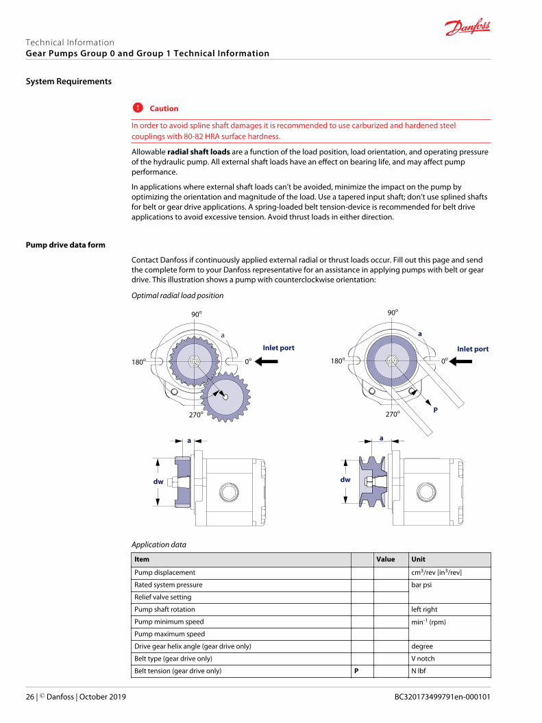
C Caution
In order to avoid spline shaft damages it is recommended to use carburized and hardened steelcouplings with 80-82 HRA surface hardness.
Allowable radial shaft loads are a function of the load position, load orientation, and operating pressureof the hydraulic pump. All external shaft loads have an effect on bearing life, and may affect pumpperformance.
In applications where external shaft loads can’t be avoided, minimize the impact on the pump byoptimizing the orientation and magnitude of the load. Use a tapered input shaft; don’t use splined shaftsfor belt or gear drive applications. A spring-loaded belt tension-device is recommended for belt driveapplications to avoid excessive tension. Avoid thrust loads in either direction.
Pump drive data form
Contact Danfoss if continuously applied external radial or thrust loads occur. Fill out this page and sendthe complete form to your Danfoss representative for an assistance in applying pumps with belt or geardrive. This illustration shows a pump with counterclockwise orientation:
Optimal radial load position
90o
a a
0o
270o
180o 0o
Inlet port Inlet port
a
dw
270o
180o
90o
dw
a
P
Application data
Item Value Unit
Pump displacement cm3/rev [in3/rev]
Rated system pressure bar psi
Relief valve setting
Pump shaft rotation left right
Pump minimum speed min-1 (rpm)
Pump maximum speed
Drive gear helix angle (gear drive only) degree
Belt type (gear drive only) V notch
Belt tension (gear drive only) P N lbf
Technical InformationGear Pumps Group 0 and Group 1 Technical Information
System Requirements
26 | © Danfoss | October 2019 BC320173499791en-000101

Application data (continued)
Item Value Unit
Angular orientation of gear or belt to inlet port ɑ degree
Pitch diameter of gear or pulley dw mm in
Distance from flange to center of gear or pulley a
Pump Life
Pump life is a function of speed, system pressure, and other system parameters (such as fluid quality andcleanliness).
All Danfoss gear pumps use hydrodynamic journal bearings that have an oil film maintained between thegear/shaft and bearing surfaces at all times. If the oil film is sufficiently sustained through proper systemmaintenance and operating within recommended limits, long life can be expected.
B10 life expectancy number is generally associated with rolling element bearings. It does not exist forhydrodynamic bearings.
High pressure, resulting from high loads, impacts pump life. When submitting an application for review,provide machine duty cycle data that includes percentages of time at various loads and speeds. Westrongly recommend a prototype testing program to verify operating parameters and their impact on lifeexpectancy before finalizing any system design.
Sound levels
Noise is unwanted sound. Fluid power systems create noise. There are many techniques available tominimize noise. Understanding how it’s generated and transmitted is necessary to apply these methodseffectively.
Noise energy is transmitted as fluid borne noise (pressure ripple) or structure borne noise. Pressureripple is the result of the number of pumping elements (gear teeth) delivering oil to the outlet and thepump’s ability to gradually change the volume of each pumping element from low to high pressure.Pressure ripple is affected by the compressibility of the oil as each pumping element discharges into theoutlet of the pump. Pressure pulsations travel along hydraulic lines at the speed of sound (about 1400m/s in oil) until there is a change in the system (as with an elbow fitting). Thus, the pressure pulsationamplitude varies with overall line length and position.
Structure borne noise may be transmitted wherever the pump casing is connected to the rest of thesystem.
The way circuit components respond to excitation depends on their size, form, and mounting. Because ofthis, a system line may actually have a greater noise level than the pump. To minimize noise, use:• flexible hoses (if you must use steel plumbing, clamp the lines).• flexible (rubber) mounts to minimize other structure borne noise.
Technical InformationGear Pumps Group 0 and Group 1 Technical Information
System Requirements
© Danfoss | October 2019 BC320173499791en-000101 | 27
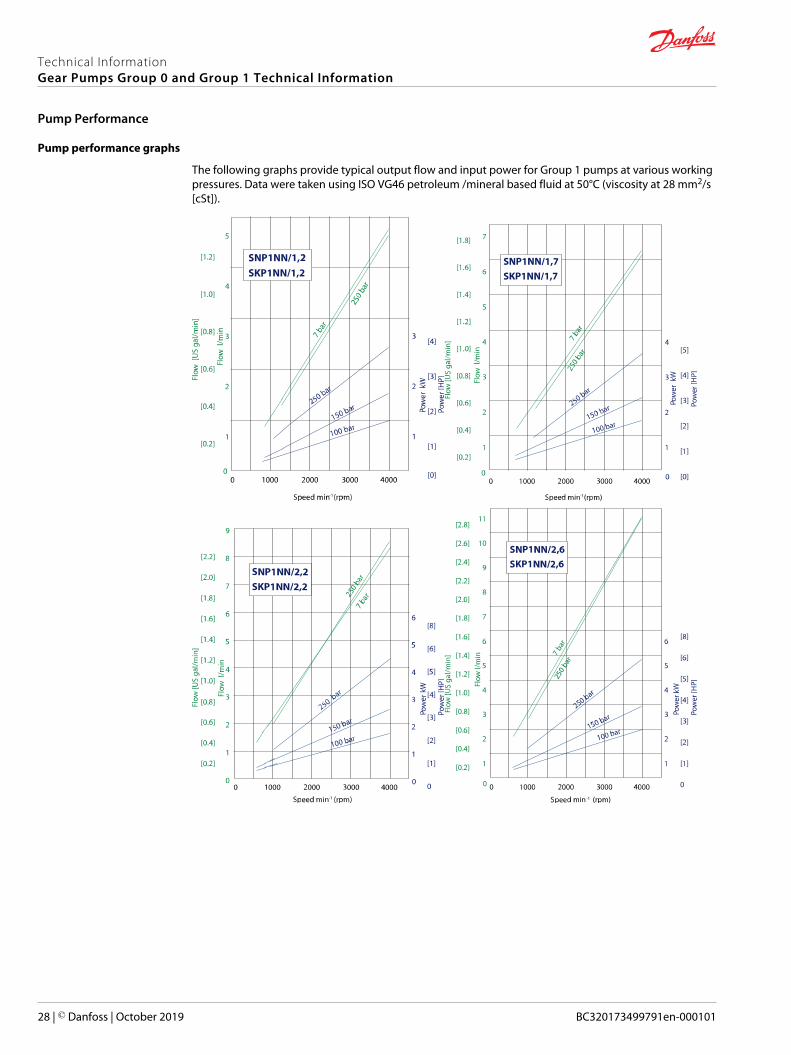
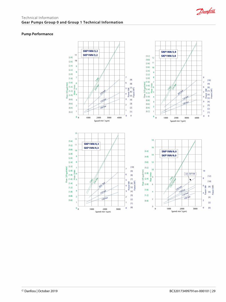
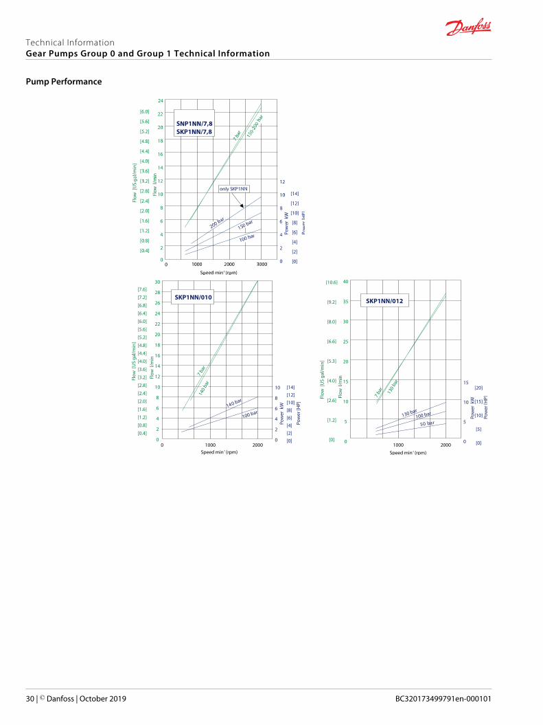
Pump performance graphs
The following graphs provide typical output flow and input power for Group 1 pumps at various workingpressures. Data were taken using ISO VG46 petroleum /mineral based fluid at 50°C (viscosity at 28 mm2/s[cSt]).
Technical InformationGear Pumps Group 0 and Group 1 Technical Information
Pump Performance
28 | © Danfoss | October 2019 BC320173499791en-000101
Technical InformationGear Pumps Group 0 and Group 1 Technical Information
Pump Performance
© Danfoss | October 2019 BC320173499791en-000101 | 29
Technical InformationGear Pumps Group 0 and Group 1 Technical Information
Pump Performance
30 | © Danfoss | October 2019 BC320173499791en-000101
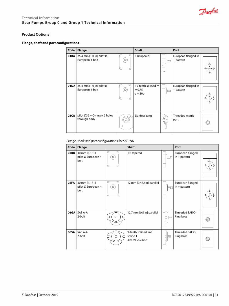
Flange, shaft and port configurations
Code Flange Shaft Port
01BA 25.4 mm [1.0 in] pilot ØEuropean 4-bolt
1:8 tapered European flanged in+ pattern
01DA 25.4 mm [1.0 in] pilot ØEuropean 4-bolt
15-teeth splined m= 0.75a = 30o
European flanged in+ pattern
03CA pilot Ø32 + O-ring + 2 holesthrough body
Danfoss tang Threaded metricport
Flange, shaft and port configurations for SKP1NN
Code Flange Shaft Port
02BB 30 mm [1.181]pilot Ø European 4-bolt
1:8 tapered European flangedin + pattern
02FA 30 mm [1.181]pilot Ø European 4-bolt
12 mm [0.472 in] parallel European flangedin + pattern
06GA SAE A-A2-bolt
12.7 mm [0.5 in] parallel Threaded SAE O-Ring boss
06SA SAE A-A2-bolt
9-teeth splined SAEspline J498-9T-20/40DP
Threaded SAE O-Ring boss
Technical InformationGear Pumps Group 0 and Group 1 Technical Information
Product Options
© Danfoss | October 2019 BC320173499791en-000101 | 31

Shaft options
Direction is viewed facing the shaft. Group 1 pumps are available with a variety of tang, splined, parallel,and tapered shaft ends. Not all shaft styles are available with all flange styles.
Shaft availability and nominal torque capability
A B C D E F G H I J K L M N O
/ ● ● /
Shaft Mounting flange code with maximum torque in Nm [lb•in]
Code Description 01 02 03 04 06 08 B1 V6
AA Taper 1:5-M6 25 [221]
BA Taper 1:8-M7 25 [221]
BB Taper 1:8-M10 50 [442]
BG Taper 1:8-M7-shaft for shortversion
25 [221]
CA Tang 5x Ø10 14 [124]
CD Tang 5x Ø11,5 distance fromgear face 47,5
17 [150]
CE Tang 6,63x Ø11 21 [186]
CF Tang 5x Ø11,5 distance fromgear face 35
21 [186]
CM Tang 5x Ø10-type 03 + w/ocoupling
14 [124]
DA Splined Z15-m0,75-alfa 30°-L14 35 [309]
DB Splined Z15-m0,75-alfa 30°-L14 35 [309]
DC Splined B12x9-L14-flangeprotrusion sb22-Z6-m1,60- alfa30°
30 [265]
DD Splined B12x9-L20-flangeprotrusion sb40-Z6-m1,75- alfa30°
30 [265]
FA Parallel Ø12-Thread M10x1 24 [212]
GA Parallel Ø12,7-Key 3.2 32 [283]
SA SAE spline J498-9T-20/40 34 [301] 34 [301]
SG SAE spline J498-8T-16/32-shaftfor short version
34 [301]
Danfoss recommends mating splines conform to SAE J498 or DIN 5482.
Danfoss external SAE splines have a flat root side fit with circular tooth thickness reduced by 0.127 mm[0.005 in] in respect to class 1 fit. Dimensions are modified to assure a clearance fit with the mating spline.
C Caution
Shaft torque capability may limit allowable pressure. Torque ratings assume no external radial loading.Applied torque must not exceed these limits, regardless of stated pressure parameters. Maximum torqueratings are based on shaft torsional fatigue strength.
Various port configurations are available on Group 1 pumps. They include:
Technical InformationGear Pumps Group 0 and Group 1 Technical Information
Product Options
32 | © Danfoss | October 2019 BC320173499791en-000101
• European standard flanged ports• German standard flanged ports• Gas threaded ports (BSPP)• O-Ring boss (following SAE J1926/1 [ISO 11926-1] UNF threads, standard)
For a table of dimensions, see Ports on page 33.
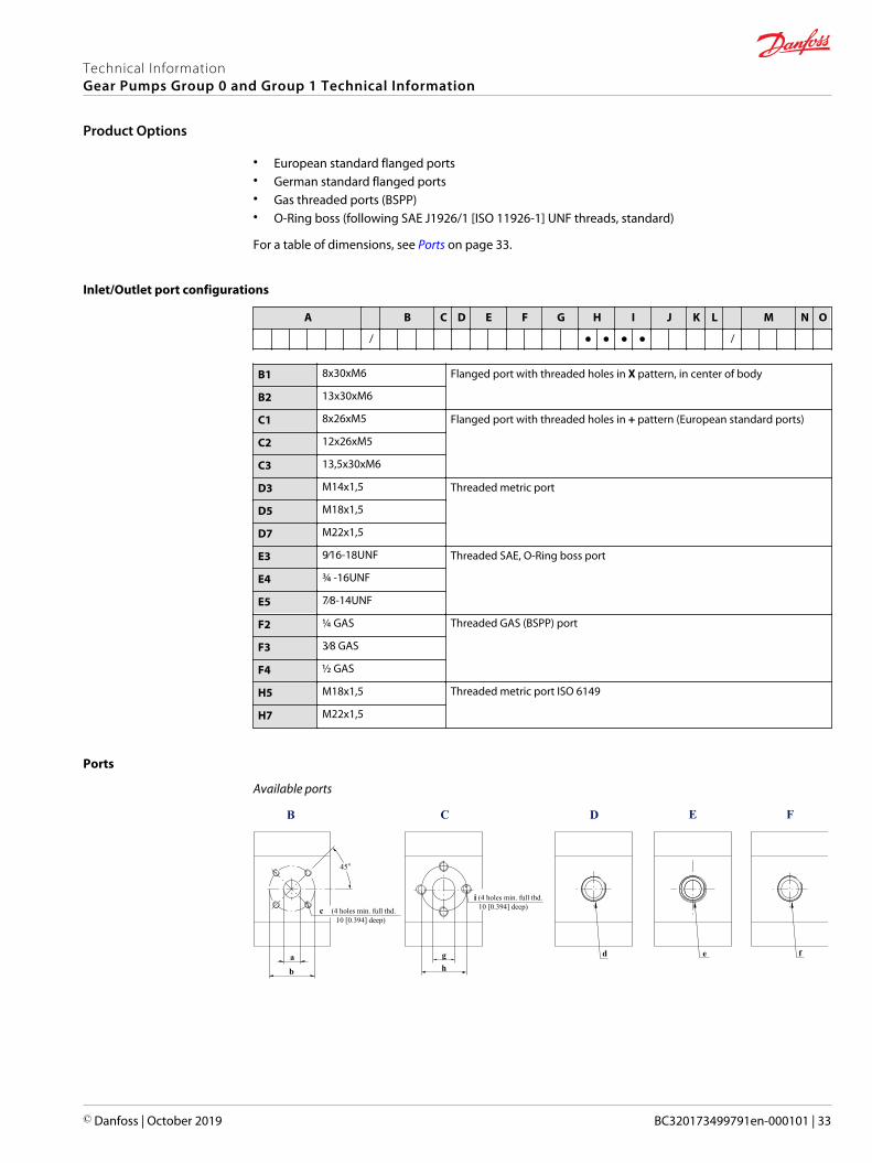
Inlet/Outlet port configurations
A B C D E F G H I J K L M N O
/ ● ● ● ● /
B1 8x30xM6 Flanged port with threaded holes in X pattern, in center of body
B2 13x30xM6
C1 8x26xM5 Flanged port with threaded holes in + pattern (European standard ports)
C2 12x26xM5
C3 13,5x30xM6
D3 M14x1,5 Threaded metric port
D5 M18x1,5
D7 M22x1,5
E3 9∕16-18UNF Threaded SAE, O-Ring boss port
E4 ¾ -16UNF
E5 7∕8-14UNF
F2 ¼ GAS Threaded GAS (BSPP) port
F3 3∕8 GAS
F4 ½ GAS
H5 M18x1,5 Threaded metric port ISO 6149
H7 M22x1,5
Ports
Available ports
g
CB D FE
h
(4 holes min. full thd.10 [0.394] deep)
a
ci
d
b
45o
(4 holes min. full thd.10 [0.394] deep)
fe
Technical InformationGear Pumps Group 0 and Group 1 Technical Information
Product Options
© Danfoss | October 2019 BC320173499791en-000101 | 33

Dimensions of Group 1 pump ports
Port type B C D E F
Port dimension a b c g h i d e f
1,2Inlet 13 [0.512] 30 [1.181] M6 12 [0.462] 26 [1.024] M5 M18x1.5 ¾–16UNF–2B 3/8 Gas (BSPP)
Outlet 8 [0.315] 30 [1.181] M6 12 [0.462] 26 [1.024] M5 M14x1.5 9/16–18UNF–2B 3/8 Gas (BSPP)
1,7Inlet 13 [0.512] 30 [1.181] M6 12 [0.462] 26 [1.024] M5 M18x1.5 ¾–16UNF–2B 3/8 Gas (BSPP)
Outlet 8 [0.315] 30 [1.181] M6 12 [0.462] 26 [1.024] M5 M14x1.5 9/16–18UNF–2B 3/8 Gas (BSPP)
2,2Inlet 13 [0.512] 30 [1.181] M6 12 [0.462] 26 [1.024] M5 M18x1.5 ¾–16UNF–2B 3/8 Gas (BSPP)
Outlet 8 [0.315] 30 [1.181] M6 12 [0.462] 26 [1.024] M5 M14x1.5 9/16–18UNF–2B 3/8 Gas (BSPP)
2,6Inlet 13 [0.512] 30 [1.181] M6 12 [0.462] 26 [1.024] M5 M18x1.5 ¾–16UNF–2B 3/8 Gas (BSPP)
Outlet 8 [0.315] 30 [1.181] M6 12 [0.462] 26 [1.024] M5 M14x1.5 9/16–18UNF–2B 3/8 Gas (BSPP)
3,2Inlet 13 [0.512] 30 [1.181] M6 12 [0.462] 26 [1.024] M5 M18x1.5 ¾–16UNF–2B 3/8 Gas (BSPP)
Outlet 8 [0.315] 30 [1.181] M6 12 [0.462] 26 [1.024] M5 M14x1.5 9/16–18UNF–2B 3/8 Gas (BSPP)
3,8Inlet 13 [0.512] 30 [1.181] M6 12 [0.462] 26 [1.024] M5 M18x1.5 ¾–16UNF–2B 3/8 Gas (BSPP)
Outlet 8 [0.315] 30 [1.181] M6 12 [0.462] 26 [1.024] M5 M18x1.5 9/16–18UNF–2B 3/8 Gas (BSPP)
4,3Inlet 13 [0.512] 30 [1.181] M6 12 [0.462] 26 [1.024] M5 M18x1.5 ¾–16UNF–2B 3/8 Gas (BSPP)
Outlet 8 [0.315] 30 [1.181] M6 12 [0.462] 26 [1.024] M5 M18x1.5 9/16–18UNF–2B 3/8 Gas (BSPP)
6,0Inlet 13 [0.512] 30 [1.181] M6 12 [0.462] 26 [1.024] M5 M18x1.5 ¾–16UNF–2B 3/8 Gas (BSPP)
Outlet 13 [0.512] 30 [1.181] M6 12 [0.462] 26 [1.024] M5 M18x1.5 9/16–18UNF–2B 3/8 Gas (BSPP)
7,8Inlet 13 [0.512] 30 [1.181] M6 12 [0.462] 26 [1.024] M5 M18x1.5 ¾–16UNF–2B 3/8 Gas (BSPP)
Outlet 13 [0.512] 30 [1.181] M6 12 [0.462] 26 [1.024] M5 M18x1.5 9/16–18UNF–2B 3/8 Gas (BSPP)
010Inlet 13 [0.512] 30 [1.181] M6 12 [0.462] 26 [1.024] M5 M18x1.5 ¾–16UNF–2B 3/8 Gas (BSPP)
Outlet 13 [0.512] 30 [1.181] M6 12 [0.462] 26 [1.024] M5 M18x1.5 9/16–18UNF–2B 3/8 Gas (BSPP)
012Inlet 13 [0.512] 30 [1.181] M6 12 [0.462] 26 [1.024] M5 M18x1.5 ¾–16UNF–2B 3/8 Gas (BSPP)
Outlet 13 [0.512] 30 [1.181] M6 12 [0.462] 26 [1.024] M5 M18x1.5 9/16–18UNF–2B 3/8 Gas (BSPP)
SNP1IN
Danfoss offers an optional integral relief valve integrated in the rear cover. It is drained internally anddirects all flow from the pump outlet to the inlet when the outlet pressure reaches the valve setting.
C Caution
When the relief valve is operating in bypass condition, rapid heat generation occurs. If this bypasscondition continues, the pump prematurely fails. The reason for this is that it is a rule, not an exception.
Technical InformationGear Pumps Group 0 and Group 1 Technical Information
Product Options
34 | © Danfoss | October 2019 BC320173499791en-000101

Valve performance graph
Dimensions
For configuration 06 (SAE A-A) dimension B and V have to be increased 4.5 mm [0.177 in].
Integral relief valve and covers dimensions
Type (displacement) 1,2 1,7 2,2 2,6 3,2 3,8 4,3 6,0 7,8 010 012
Dimensions mm[in]
B 95.5[3.760]
97[3.819]
99[3.989]
101[3.976]
103[4.055]
105[4.134]
107[4.213]
113.5[4.468]
120[4.724]
129[5.079]
137[5.394]
V 85.0[3.346]
86.5[3.406]
88.5[3.484]
90.5[3.563]
92.5[3.642]
94.5[3.720]
96.5[3.799]
103.0[4.055]
109.5[4.311]
118.5[4.665]
126.5[4.980]
Variant codes for ordering integral relief valves
These tables detail the various codes for ordering integral relief valves:
A B C D E F G H I J K L M N O
/ / ● ● ●
Technical InformationGear Pumps Group 0 and Group 1 Technical Information
Product Options
© Danfoss | October 2019 BC320173499791en-000101 | 35

CodePump speed for RV setting
min-1 (rpm)
A Not defined
C 500
E 1000
F 1250
G 1500
K 2000
I 2250
L 2500
M 2800
N 3000
O 3250
CodePressure setting
bar [psi]
A No setting
B No valve
C 18 [261]
D 25 [363]
E 30 [435]
F 35 [508]
G 40 [580]
K 50 [725]
L 60 [870]
M 70 [1015]
N 80 [1160]
O 90 [1305]
P 100 [1450]
Q 110 [1595]
R 120 [1740]
S 130 [1885]
T 140 [2030]
U 160 [2320]
V 170 [2465]
W 180 [2611]
X 210 [3045]
Y 240 [3480]
Z 250 [3626]
Technical InformationGear Pumps Group 0 and Group 1 Technical Information
Product Options
36 | © Danfoss | October 2019 BC320173499791en-000101
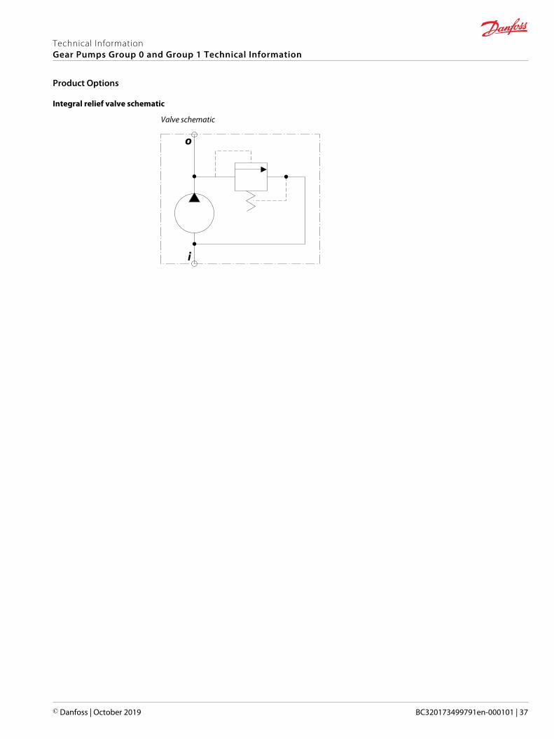
Integral relief valve schematic
Valve schematic
Technical InformationGear Pumps Group 0 and Group 1 Technical Information
Product Options
© Danfoss | October 2019 BC320173499791en-000101 | 37

SNP1NN - 01BA and 01DA
This drawing shows the standard porting for 01BA and 01DA. Available in Series SNP1NN only.
01BA 01DA
1:8
Cone
refe
renc
e di
amet
er
to cone reference diameter
Recommended tightening torque: 7-12 Nm
Distance from front flange
29 [1.14]
M7-
6g
14.4 [0.583] 5.2 [0.205]
12.4 [0.488]
X
Pilot width
-0.0
41-0
.020
16.5 [0.65]4.2 [0.165]
XØ
0.7
5 [0
.029
5]
body width
69.4 [2.73] max
52.4 [2.06]
88.1
[3.4
7] m
ax
74.5
[2.9
3] m
ax
(53.
8 [2
.12]
max
)(3
4.3
[1.3
5] m
ax)
(71.
9 [2
.83]
26.2
[1.0
3]45
.7 [1
.8]
68 ±0.25 [2.68 ±0.010]
5.5 [0.217 ]+0.15-0.25
+0.0059-0.0098
-0.00982.41 [0.0949 ] 0-0.025
0
D/d
E/e
C/c
Spline:Z=15 M=0.75 alfa=30°Circular tooth thickness: 1.028-1.068 [0.04 0-0.042] Internal spline dia: 9.8-10 [0.386-0.394]
to shoulderfront flangeDistance from
4.5 [0.177]
14 [0.551]
21.5 [0.846]
(min full thd 10 [0.394] deep)
±0.50 [0.020]
±0.20 [0.008]
B max
A
A
A
A-A
Ø 2
5.4
[1.0
]
Ø 9
.82
[0.3
87]
10.8
±0.5
0 [0
.425
±0.
020]
Ø 1
1.9
[0.4
69
]
Ø 7
.2 -
8 [0
.283
-0.3
15]
0 -0.1
100 -0
.004
-0.0
016
-0.0
008
SNP1NN – 01BA and 01DA dimensions
Frame size 1,2 1,7 2,2 2,6 3,2 3,8 4,3 6,0 7,8
Dimension A 37.75[1.486]
38.5[1.516]
39.5[1.555]
40.5[1.634]
41.5[1.634]
42.5[1.673]
43.5[1.713]
46.75[1.841]
50.0[1.969]
B 79.5[3.130]
81.0[3.189]
83.0[3.268]
85.0[3.346]
87.0[3.425]
89.0[3.504]
91.0[3.583]
97.5[3.839]
104.0[4.094]
Inlet/Outlet C/c 12 [0.472]
D/d 26 [1.024]
E/e M5
Model code examples and maximum shaft torque
Flange/drive gear Model code example Maximum shaft torque
01BA SNP1NN/3,8RN01BAP1C2C2NNNN/NNNNN 25 N•m [221 lb•in]
01DA SNP1NN/6,0LN01DAP1C2C2NNNN/NNNNN 35 N•m [310 lb•in]
For further details on ordering, see Model code.
Technical InformationGear Pumps Group 0 and Group 1 Technical Information
Dimensions
38 | © Danfoss | October 2019 BC320173499791en-000101

SKP1NN – 02BB and 02FA
This drawing shows the standard porting for 02BB and 02FA. Available in Series SKP1NN only.
12.0
[0
.472
]+0
.0
+0
.0-0
.018
-0
.001
M10
x 1
-6g
11.7 [0.461]
8.3 [0.327]Distance from front flange to shoulder
31.5 [1.240]
3.0 [0.118 ]+0.0 +0.0-0.030 -0.001
13.2 [0.520 ]+0.05 +0.002-0.20 -0.008
88.2
[3.4
72] m
ax
7.5 [0.295 ]+0.25 +0.010-0.15 -0.006
3.0 [0.118 ]0 0-0.030 -0.001
C/c
D/dE/e
A
16.5 [0.650]
7.0 [0.276]Pilot width
8.0 [0.315] Distance from front flangeto cone reference diameter
B max
M10
x1-6
g
Ø13
.95
[0.5
49]
Cone
refe
renc
e di
amet
er
10.8
[0
.425
30.0
[1
.181
]
-0.0
20
-
0.00
08-0
.041
-0.
0016
68.0 ±0.25[2.677 ±0.010]body width
74.5
[2.9
33] m
ax
56.0 [2.205]
70.9 [2.791] max
24.5
[0.9
65]
48.5
[1.9
09]
(73.
0 [2
.874
])
(32.
1 [1
.264
] max
)(5
6.1
[2.2
09] m
ax)
Ø6.
7-7.
5 [0
.264
-0.2
95]
1:8
35 [1.378]
15.75 [0.620]
15.5 [0.610]
±0.20 [±0.008]
±0.5
0
±
0.02
0]
±0.50 [±0.02]
02BB 02FA
(min full thd 10 mm [0.394] deep)
A
A
A-A
B
B
B-B
XØ
0.7
5 [0
.029
5]
X
Recommended tightening torque: 10-16 Nm
Recommended tightening torque: 10-16 Nm
SKP1NN – 02BB and 02FA dimensions
Frame size 1,2 1,7 2,2 2,6 3,2 3,8 4,3 6,0 7,8 010 012
Dimension A 37.75[1.486]
38.5[1.516]
39.5[1.555]
40.5[1.634]
41.5[1.634]
42.5[1.673]
43.5[1.713]
46.75[1.841]
50.0[1.969]
54.5[2.146]
58.5[2.303]
B 79.5[3.130]
81.0[3.189]
83.0[3.268]
85.0[3.346]
87.0[3.425]
89.0[3.504]
91.0[3.583]
97.5[3.839]
104.0[4.094]
113.0[4.449]
121.0[4.764]
Inlet/Outlet C/c 12 [0.472]
D/d 26 [1.024]
E/e M5
Model code examples and maximum shaft torque
Flange/drive gear Model code example Maximum shaft torque
02BB SKP1NN/6,0RN02BBP1C2C2NNNN/NNNNN 50 N•m [442 lb•in]
02FA SKP1NN/ 2,2LN02FAP1C2C2NNNN/NNNNN 24 N•m [212 lb•in]
For further details on ordering, see Model code.
Technical InformationGear Pumps Group 0 and Group 1 Technical Information
Dimensions
© Danfoss | October 2019 BC320173499791en-000101 | 39

SNP1NN – 03CA
This drawing shows the standard porting for 03CA.
C/c 2.5 [0.098] 22.7
5 [0
.896
] min
2.0 [0.079]
OR 28.30 x 1.78
8.5 [0.335]
22.0
[0.8
66]
body width
74.5
[2.9
33] m
ax
Ø8.5-9.0 [0.335-0.354]
40.0 [1.575]
40.
0 [1
.575
]29
.65
[1.1
67]
10.3
5 [0
.407
]
8.5 [0.335] maxA ±0.50 [±0.020]
B ±1.0 [±0.039]
10.8
±0.5
0 [0
.425
±0.0
20]
63.0 ±0.25 [2.48 ±0.01]
4.8 ±0.10 [0.189 ±0.004]
0.8 -0.30
[0.031 -0.012]
7.0 [0.276]Pilot width
5.0
-0.0
80 [0
.197
-0.0
03]
+0.0
20+0
.001
+0.040
+0.016
32.0
-0.0
50 [1
.260
-0.0
02]
-0.0
25-0
.001
XØ 0.4 [0.016]
03CA
X
SNP1NN – 03CA dimensions
Frame size 1,2 1,7 2,2 2,6 3,2 3,8 4,3 6,0 7,8
Dimension A 37.75[1.486]
38.5[1.516]
39.5[1.555]
40.5[1.634]
41.5[1.634]
42.5[1.673]
43.5[1.713]
46.75[1.841]
50[1.969]
B 70[2.756]
71.5[2.815]
73.5[2.894]
75.5[2.972]
77.5[3.051]
79.5[3.130]
81.5[3.209]
88.0[3.465]
94.5[3.720]
Inlet C M18 x 1.5 THD 12 [0.472] deep
Outlet c M14 x 1.5, THD 12 [0.472] deep M18 x 1.5, THD 12 [0.472] deep
Model code examples and maximum shaft torque
Flange/drive gear Model code example Maximum shaft torque
03CA SNP1NN/1,7RN03CA03D5D3NNNN/NNNNN 14 N•m [124 lb•in]
For further details ordering, see Model code.
Technical InformationGear Pumps Group 0 and Group 1 Technical Information
Dimensions
40 | © Danfoss | October 2019 BC320173499791en-000101
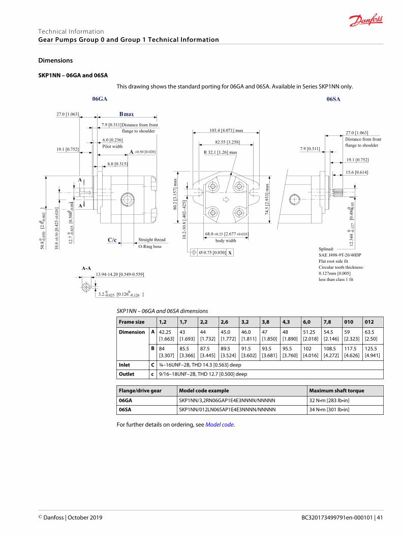
SKP1NN – 06GA and 06SA
This drawing shows the standard porting for 06GA and 06SA. Available in Series SKP1NN only.
12.3
44
[0
.486
]
0
0 0
0 -0.0
5
Splined: SAE J498-9T-20/40DPFlat root side fitCircular tooth thickness:0.127mm [0.005]less than class 1 fit
15.6 [0.614]
19.1 [0.752]
7.9 [0.311]
27.0 [1.063]
74.5
[2.9
33] m
ax
body width
R 32.1 [1.26] max
82.55 [3.258]
103.4 [4.071] max
80.2
[3.1
57] m
ax
X
10.2
-10.
8 [.4
02-.4
25]
Ø 0.75 [0.030]
3.2 [0.126 ]-0.025 -0.126
13.94-14.20 [0.549-0.559]
Straight thread O-Ring boss
8.0 [0.315]
6.0 [0.236]Pilot width
7.9 [0.311]Distance from front flange to shoulder
Distance from front flange to shoulder
19.1 [0.752]
27.0 [1.063]
12.7
[
0.50
0
]
-0.0
25
-0.0
01
10.8
±0.
50 [0
.425
±0.0
20]
68.0 ±0.25 [2.677 ±0.010]
50.8
[
2.0
]
0
0-0
.050
-0
.002
06GA 06SA
C/c
±0.50 [0.020]
B max
A
A
A
A-A
-0.1
27
00
SKP1NN – 06GA and 06SA dimensions
Frame size 1,2 1,7 2,2 2,6 3,2 3,8 4,3 6,0 7,8 010 012
Dimension A 42.25[1.663]
43[1.693]
44[1.732]
45.0[1.772]
46.0[1.811]
47[1.850]
48[1.890]
51.25[2.018]
54.5[2.146]
59[2.323]
63.5[2.50]
B 84[3.307]
85.5[3.366]
87.5[3.445]
89.5[3.524]
91.5[3.602]
93.5[3.681]
95.5[3.760]
102[4.016]
108.5[4.272]
117.5[4.626]
125.5[4.941]
Inlet C ¾–16UNF–2B, THD 14.3 [0.563] deep
Outlet c 9/16–18UNF–2B, THD 12.7 [0.500] deep
Flange/drive gear Model code example Maximum shaft torque
06GA SKP1NN/3,2RN06GAP1E4E3NNNN/NNNNN 32 N•m [283 lb•in]
06SA SKP1NN/012LN06SAP1E4E3NNNN/NNNNN 34 N•m [301 lb•in]
For further details on ordering, see Model code.
Technical InformationGear Pumps Group 0 and Group 1 Technical Information
Dimensions
© Danfoss | October 2019 BC320173499791en-000101 | 41
Danfoss Power Solutions is a global manufacturer and supplier of high-quality hydraulic andelectric components. We specialize in providing state-of-the-art technology and solutionsthat excel in the harsh operating conditions of the mobile off-highway market as well as themarine sector. Building on our extensive applications expertise, we work closely with you toensure exceptional performance for a broad range of applications. We help you and othercustomers around the world speed up system development, reduce costs and bring vehiclesand vessels to market faster.
Danfoss Power Solutions – your strongest partner in mobile hydraulics and mobileelectrification.
Go to www.danfoss.com for further product information.
We offer you expert worldwide support for ensuring the best possible solutions foroutstanding performance. And with an extensive network of Global Service Partners, we alsoprovide you with comprehensive global service for all of our components.
Local address:
Danfoss Power Solutions GmbH & Co. OHGKrokamp 35D-24539 Neumünster, GermanyPhone: +49 4321 871 0
Danfoss Power Solutions ApSNordborgvej 81DK-6430 Nordborg, DenmarkPhone: +45 7488 2222
Danfoss Power Solutions (US) Company2800 East 13th StreetAmes, IA 50010, USAPhone: +1 515 239 6000
Danfoss Power Solutions Trading(Shanghai) Co., Ltd.Building #22, No. 1000 Jin Hai RdJin Qiao, Pudong New DistrictShanghai, China 201206Phone: +86 21 2080 6201
Danfoss can accept no responsibility for possible errors in catalogues, brochures and other printed material. Danfoss reserves the right to alter its products without notice. This also applies to productsalready on order provided that such alterations can be made without subsequent changes being necessary in specifications already agreed.All trademarks in this material are property of the respective companies. Danfoss and the Danfoss logotype are trademarks of Danfoss A/S. All rights reserved.
© Danfoss | October 2019 BC320173499791en-000101
Products we offer:
• DCV directional controlvalves
• Electric converters
• Electric machines
• Electric motors
• Gear motors
• Gear pumps
• Hydrostatic motors
• Hydrostatic pumps
• Orbital motors
• PLUS+1® controllers
• PLUS+1® displays
• PLUS+1® joysticks andpedals
• PLUS+1® operatorinterfaces
• PLUS+1® sensors
• PLUS+1® software
• PLUS+1® software services,support and training
• Position controls andsensors
• PVG proportional valves
• Steering components andsystems
• Telematics
Hydro-Gearwww.hydro-gear.com
Daikin-Sauer-Danfosswww.daikin-sauer-danfoss.com