ge snp driver help - kepware technologies
TRANSCRIPT

GE SNP Driver
© 2018 PTC Inc. All Rights Reserved.

GE SNP Driver
Table of Contents
GE SNP Driver 1
Table of Contents 2
GE SNP Driver 6
Overview 6
Setup 7
Channel Properties — General 7
Channel Properties — Serial Communications 8
Channel Properties — Write Optimizations 11
Channel Properties — Advanced 12
Channel Properties — Communication Serialization 13
Device Properties — General 14
Device Properties — ScanMode 16
Device Properties — Timing 16
Device Properties — Auto-Demotion 17
Device Properties — Tag Generation 18
Device Properties - Variable Import Settings 20
Device Properties — Redundancy 20
Data Types Description 22
Automatic Tag Database Generation 23
Tag Hierarchy 23
Import File-to-Server NameConversions 23
Address Descriptions 26
GEMicro Addressing 26
311 Addressing 27
313 Addressing 28
331 Addressing 29
341 Addressing 29
350 Addressing 30
360 Addressing 31
731 Addressing 32
732 Addressing 33
771 Addressing 34
772 Addressing 35
781 Addressing 36
782 Addressing 36
www.ptc.com
2

GE SNP Driver
GEOPEN Addressing 37
Advanced Addressing 38
Error Descriptions 41
Missing address 43
Device address '<address>' contains a syntax error 43
Address '<address>' is out of range for the specified device or register 43
Device address '<address>' is not supported by model '<model name>' 44
Data Type '<type>' is not valid for device address '<address>' 44
Device address '<address>' is Read Only 44
Array size is out of range for address '<address>' 44
Array support is not available for the specified address: '<address>' 45
COMn does not exist 45
Error opening COMn 45
COMn is in use by another application 45
Unable to set comm parameters on COMn 46
Communications error on '<channel name>' [<error mask>] 46
Device '<device name>' not responding 46
Unable to write to '<address>' on device '<device name>' 47
Invalid tag in block starting at <address> on device <device name>. Block deactivated 47
Unable to write to tag '<tag address>' on device '<device name>'. The service requested is eithernot defined or not supported 47
Unable to write to tag '<tag address>' on device '<device name>'. The user does not havesufficient privileges to process the request. Minor status error code = '<hexadecimal error code>' 48
Unable to write to tag '<tag address>' on device '<device name>'. The CPU has received amessage that is out of order 48
Unable to write to tag '<tag address>' on device '<device name>'. Service request error. Minorstatus error code = '<hexadecimal error code>' 48
Unable to write to tag '<tag address>' on device '<device name>'. Service request mailbox type iseither undefined or unexpected 48
Unable to write to tag '<tag address>' on device '<device name>'. The PLC CPU's service requestqueue is full: please wait a minimum of 10 ms before sending another service request 49
Unable to write to tag '<tag address>' on device '<device name>'. A framing error has occurred 49
Unable to write to tag '<tag address>' on device '<device name>'. Device returnedmajor errorcode '<hexadecimal error code>' andminor error code '<hexadecimal error code>' 49
Unable to read '<number of bytes>' bytes starting at address '<tag address>' on device '<devicename>'. The service requested is either not defined or not supported 50
Unable to read '<number of bytes>' bytes starting at address '<tag address>' on device '<devicename>'. The user does not have sufficient privileges to process the request. Minor status errorcode = '<hexadecimal error code>' 50
Unable to read '<number of bytes>' bytes starting at address '<tag address>' on device '<devicename>'. The CPU has received a message that is out of order 50
www.ptc.com
3

GE SNP Driver
Unable to read '<number of bytes>' bytes starting at address '<tag address>' on device '<devicename>'. Service request error. Minor status error code = '<hexadecimal error code>' 50
Unable to read '<number of bytes>' bytes starting at address '<tag address>' on device '<devicename>'. Service request mailbox type is either undefined or unexpected 51
Unable to read ' <number of bytes>' bytes starting at address '<tag address>' on device '<devicename>'. The PLC CPU's service request queue is full: please wait a minimum of 10 ms beforesending another service request 51
Unable to read '<byte count>' bytes starting at address '<start tag>' on device '<device name>'. Aframing error has occurred 51
Unable to read '<number of bytes>' bytes starting at address '<tag address>' on device '<devicename>'. Device returnedmajor error code '<hexadecimal error code>' andminor error code'<hexadecimal error code>' 52
Unable to read tag '<tag address>' on device '<device name>'. The service requested is either notdefined or not supported 52
Unable to read tag '<tag address>' on device '<device name>'. The user does not have sufficientprivileges to process the request. Minor status error code = '<hexadecimal error code>' 52
Unable to read tag '<tag address>' on device '<device name>'. The CPU has received a messagethat is out of order 53
Unable to read tag '<tag address>' on device '<device name>'. Service request error. Minorstatus error code = '<hexadecimal error code>' 53
Unable to read tag '<tag address>' on device '<device name>'. Service request mailbox type iseither undefined or unexpected 53
Unable to read tag '<tag address>' on device '<device name>'. The PLC CPU's service requestqueue is full: please wait a minimum of 10 ms before sending another service request 53
Unable to read tag '<tag address>' on device '<device name>'. A framing error has occurred 54
Unable to read tag '<tag address>' on device '<device name>'. Device returnedmajor error code'<hexadecimal error code>' andminor error code '<hexadecimal error code>' 54
Unable to generate a tag database for device <device name>. Reason: Import file is invalid orcorrupt 54
Unable to generate a tag database for device <device name>. Reason: Lowmemory resources 55
Database Error: Tag '<orig. tag name>' exceeds 256 characters. Tag renamed to '<new tagname>' 55
Database Error: Array tags '<orig. tag name><dimensions>' exceed 256 characters. Tagsrenamed to '<new tag name><dimensions>' 55
Database Error: Datatype '<type>' for tag '<tag name>' not found in import file. Setting to default 56
Database Error: Datatype '<type>' for tag '<tag name>' is currently not supported. Tag notcreated 56
Database Error: Logic Developer Variable Arrays are currently not supported. Array Tag(s)'<array tag name>' not created 56
Database Error: No Reference Address found for tag '<tag name>' in import file. Tag not created 56
Database Error: Only variables with Data Source '<data source name>' are imported. DataSource '<data source name>' is not supported. Tag '<tag name>' not created 57
Database Error: Data type '<type>' arrays are currently not supported. Tag '<array tag name>' 57
www.ptc.com
4

GE SNP Driver
not created
Appendix: Creating Tag Import Files 58
Importing VersaPro Tags 59
VersaPro Import Preparation: VersaPro Steps 59
VersaPro Import Preparation: OPC Server Steps 61
Highlighting VersaPro Variables 61
VersaPro Array Tag Import 62
Importing LogicDeveloper Tags 63
LogicDeveloper Import Preparation: LogicDeveloper Steps 63
LogicDeveloper Import Preparation: OPC Server Steps 65
Highlighting LogicDeveloper Variables 66
LogicDeveloper Array Tag Import 66
Importing Proficy Logic Developer Tags 66
Proficy Logic Developer Import Preparation: Logic Developer Steps 67
Proficy Logic Developer Import Preparation: OPC Server Steps 69
Highlighting Proficy Logic Developer Variables 69
Proficy Logic Developer Array Tag Import 70
Index 71
www.ptc.com
5

GE SNP Driver
GE SNP DriverHelp version 1.032
CONTENTS
OverviewWhat is the GE SNP Driver?
Device SetupHow do I configure a device for use with this driver?
Data Types DescriptionWhat data types does this driver support?
Address DescriptionsHow do I address a data location on a GE SNP device?
Automatic Tag Database GenerationHow can I easily configure tags for the GE SNP Driver?
Error DescriptionsWhat error messages does the driver produce?
OverviewThe GE SNP Driver provides a reliable way to connect GE SNP controllers to client applications; includingHMI, SCADA, Historian, MES, ERP and countless custom applications. This driver is intended for use with GEProgrammable Logic Controllers.
www.ptc.com
6

GE SNP Driver
SetupSupported DevicesSeries GE MicroSeries 90-30 311/313, 331/341, 350, 360Series 90-70 731/732, 771/772, 781/782GE OPEN Wide range model support
Communication ProtocolGE SNP
Supported Communication ParametersBaud Rate: 300, 600, 1200, 2400, 9600 and 19200Parity: Odd, NoneData Bits: 8Stop Bits: 1
Device IDsSeries 90-30 PLCs support up to 6-character strings. For example, 1 and Ge3.Series 90-70 PLCs support up to 7-character strings. For example, 1, Ge7 and Ge.
Note: For peer-to-peer communications, an empty string is a valid Device ID.
Flow ControlWhen using an RS232/RS485 converter, the type of flow control that is required will depend upon the needsof the converter. Some converters do not require any flow control whereas others require RTS flow. Consultthe converter's documentation to determine its flow requirements. An RS485 converter that providesautomatic flow control is recommended.
Note: When using the manufacturer's supplied communications cable, it is sometimes necessary tochoose a flow control setting of RTS or RTS Always under the Channel Properties.
Automatic Tag Database GenerationFor more information, refer to GE SNP Variable Import Settings.
CablingFollow the manufacturer's suggested cabling for the communications port and communications module.
Channel Properties — GeneralThis server supports the use of simultaneous multiple communications drivers. Each protocol or driver usedin a server project is called a channel. A server project may consist of many channels with the samecommunications driver or with unique communications drivers. A channel acts as the basic building block ofan OPC link. This group is used to specify general channel properties, such as the identification attributesand operating mode.
www.ptc.com
7

GE SNP Driver
Identification
Name: User-defined identity of this channel. In each server project, each channel name must be unique.Although names can be up to 256 characters, some client applications have a limited display window whenbrowsing the OPC server's tag space. The channel name is part of the OPC browser information.For information on reserved characters, refer to "How To... Properly Name a Channel, Device, Tag, and Tag
Group" in the server help.
Description: User-defined information about this channel. Many of these properties, including Description, have an associated system tag.
Driver: Selected protocol / driver for this channel. This property specifies the device driver that was selectedduring channel creation. It is a disabled setting in the channel properties.
Note: With the server's online full-time operation, these properties can be changed at any time. Thisincludes changing the channel name to prevent clients from registering data with the server. If a client hasalready acquired an item from the server before the channel name is changed, the items are unaffected. If,after the channel name has been changed, the client application releases the item and attempts to re-acquire using the old channel name, the item is not accepted. With this in mind, changes to the propertiesshould not be made once a large client application has been developed. Utilize the User Manager to preventoperators from changing properties and restrict access rights to server features.
Diagnostics
Diagnostics Capture: When enabled, this optionmakes the channel's diagnostic information available toOPC applications. Because the server's diagnostic features require a minimal amount of overheadprocessing, it is recommended that they be utilized when needed and disabled when not. The default isdisabled.Note: This property is not available if the driver does not support diagnostics.For more information, refer to "Communication Diagnostics" in the server help.
Channel Properties — Serial CommunicationsSerial communication properties are available to serial drivers and vary depending on the driver, connectiontype, and options selected. Below is a superset of the possible properties.Click to jump to one of the sections: Connection Type, Serial Port Settings or Ethernet Settings, andOperational Behavior.
Note: With the server's online full-time operation, these properties can be changed at any time. Utilizethe User Manager to restrict access rights to server features, as changes made to these properties cantemporarily disrupt communications.
www.ptc.com
8

GE SNP Driver
Connection Type
Physical Medium: Choose the type of hardware device for data communications. Options include COMPort, None, Modem, and Ethernet Encapsulation. The default is COM Port.
l None: Select None to indicate there is no physical connection, which displays the Operation with noCommunications section.
l COM Port: Select Com Port to display and configure the Serial Port Settings section.
l Modem: Select Modem if phone lines are used for communications, which are configured in theModem Settings section.
l Ethernet Encap.: Select if Ethernet Encapsulation is used for communications, which displays theEthernet Settings section.
l Shared: Verify the connection is correctly identified as sharing the current configuration with anotherchannel. This is a read-only property.
Serial Port Settings
COM ID: Specify the Communications ID to be used when communicating with devices assigned to thechannel. The valid range is 1 to 9991 to 16. The default is 1.
Baud Rate: Specify the baud rate to be used to configure the selected communications port.
Data Bits: Specify the number of data bits per data word. Options include 5, 6, 7, or 8.
Parity: Specify the type of parity for the data. Options include Odd, Even, or None.
Stop Bits: Specify the number of stop bits per data word. Options include 1 or 2.
Flow Control: Select how the RTS and DTR control lines are utilized. Flow control is required to communicatewith some serial devices. Options are:
l None: This option does not toggle or assert control lines.
l DTR: This option asserts the DTR line when the communications port is opened and remains on.
www.ptc.com
9

GE SNP Driver
l RTS: This option specifies that the RTS line is high if bytes are available for transmission. After allbuffered bytes have been sent, the RTS line is low. This is normally used with RS232/RS485 converterhardware.
l RTS, DTR: This option is a combination of DTR and RTS.
l RTS Always: This option asserts the RTS line when the communication port is opened and remainson.
l RTS Manual: This option asserts the RTS line based on the timing properties entered for RTS LineControl. It is only available when the driver supports manual RTS line control (or when the propertiesare shared and at least one of the channels belongs to a driver that provides this support).RTS Manual adds an RTS Line Control property with options as follows:
l Raise: This property specifies the amount of time that the RTS line is raised prior to datatransmission. The valid range is 0 to 9999 milliseconds. The default is 10 milliseconds.
l Drop: This property specifies the amount of time that the RTS line remains high after datatransmission. The valid range is 0 to 9999 milliseconds. The default is 10 milliseconds.
l Poll Delay: This property specifies the amount of time that polling for communications isdelayed. The valid range is 0 to 9999. The default is 10 milliseconds.
Tip: When using two-wire RS-485, "echoes" may occur on the communication lines. Since thiscommunication does not support echo suppression, it is recommended that echoes be disabled or a RS-485converter be used.
Operational Behavior
l Report Comm. Errors: Enable or disable reporting of low-level communications errors. Whenenabled, low-level errors are posted to the Event Log as they occur. When disabled, these sameerrors are not posted even though normal request failures are. The default is Enable.
l Close Idle Connection: Choose to close the connection when there are no longer any tags beingreferenced by a client on the channel. The default is Enable.
l Idle Time to Close: Specify the amount of time that the server waits once all tags have beenremoved before closing the COM port. The default is 15 seconds.
Ethernet SettingsNote: Not all serial drivers support Ethernet Encapsulation. If this group does not appear, the functionality
is not supported.
Ethernet Encapsulation provides communication with serial devices connected to terminal servers on theEthernet network. A terminal server is essentially a virtual serial port that converts TCP/IP messages on theEthernet network to serial data. Once the message has been converted, users can connect standard devicesthat support serial communications to the terminal server. The terminal server's serial port must beproperly configured to match the requirements of the serial device to which it is attached. For moreinformation, refer to "How To... Use Ethernet Encapsulation" in the server help.
l Network Adapter: Indicate a network adapter to bind for Ethernet devices in this channel. Choose anetwork adapter to bind to or allow the OS to select the default.Specific drivers may display additional Ethernet Encapsulation properties. For more information, refer
to Channel Properties — Ethernet Encapsulation.
Modem Settings
www.ptc.com
10

GE SNP Driver
l Modem: Specify the installed modem to be used for communications.
l Connect Timeout: Specify the amount of time to wait for connections to be established beforefailing a read or write. The default is 60 seconds.
l Modem Properties: Configure the modem hardware. When clicked, it opens vendor-specific modemproperties.
l Auto-Dial: Enables the automatic dialing of entries in the Phonebook. The default is Disable. Formore information, refer to "Modem Auto-Dial" in the server help.
l Report Comm. Errors: Enable or disable reporting of low-level communications errors. Whenenabled, low-level errors are posted to the Event Log as they occur. When disabled, these sameerrors are not posted even though normal request failures are. The default is Enable.
l Close Idle Connection: Choose to close the modem connection when there are no longer any tagsbeing referenced by a client on the channel. The default is Enable.
l Idle Time to Close: Specify the amount of time that the server waits once all tags have beenremoved before closing the modem connection. The default is 15 seconds.
Operation with no Communications
l Read Processing: Select the action to be taken when an explicit device read is requested. Optionsinclude Ignore and Fail. Ignore does nothing; Fail provides the client with an update that indicatesfailure. The default setting is Ignore.
Channel Properties — Write OptimizationsAs with any server, writing data to the device may be the application's most important aspect. The serverintends to ensure that the data written from the client application gets to the device on time. Given this goal,the server provides optimization properties that can be used to meet specific needs or improve applicationresponsiveness.
Write Optimizations
Optimization Method: controls how write data is passed to the underlying communications driver. Theoptions are:
l Write All Values for All Tags: This option forces the server to attempt to write every value to thecontroller. In this mode, the server continues to gather write requests and add them to the server'sinternal write queue. The server processes the write queue and attempts to empty it by writing datato the device as quickly as possible. This mode ensures that everything written from the clientapplications is sent to the target device. This mode should be selected if the write operation order orthe write item's content must uniquely be seen at the target device.
l Write Only Latest Value for Non-Boolean Tags: Many consecutive writes to the same value canaccumulate in the write queue due to the time required to actually send the data to the device. If theserver updates a write value that has already been placed in the write queue, far fewer writes areneeded to reach the same final output value. In this way, no extra writes accumulate in the server's
www.ptc.com
11

GE SNP Driver
queue. When the user stops moving the slide switch, the value in the device is at the correct value atvirtually the same time. As the mode states, any value that is not a Boolean value is updated in theserver's internal write queue and sent to the device at the next possible opportunity. This can greatlyimprove the application performance.
Note: This option does not attempt to optimize writes to Boolean values. It allows users tooptimize the operation of HMI data without causing problems with Boolean operations, such as amomentary push button.
l Write Only Latest Value for All Tags: This option takes the theory behind the second optimizationmode and applies it to all tags. It is especially useful if the application only needs to send the latestvalue to the device. This mode optimizes all writes by updating the tags currently in the write queuebefore they are sent. This is the default mode.
Duty Cycle: is used to control the ratio of write to read operations. The ratio is always based on one read forevery one to ten writes. The duty cycle is set to ten by default, meaning that ten writes occur for each readoperation. Although the application is performing a large number of continuous writes, it must be ensuredthat read data is still given time to process. A setting of one results in one read operation for every writeoperation. If there are no write operations to perform, reads are processed continuously. This allowsoptimization for applications with continuous writes versus a more balanced back and forth data flow.
Note: It is recommended that the application be characterized for compatibility with the writeoptimization enhancements before being used in a production environment.
Channel Properties — AdvancedThis group is used to specify advanced channel properties. Not all drivers support all properties; so theAdvanced group does not appear for those devices.
Non-Normalized Float Handling: A non-normalized value is defined as Infinity, Not-a-Number (NaN), or asa Denormalized Number. The default is Replace with Zero. Drivers that have native float handling maydefault to Unmodified. Non-normalized float handling allows users to specify how a driver handles non-normalized IEEE-754 floating point data. Descriptions of the options are as follows:
l Replace with Zero: This option allows a driver to replace non-normalized IEEE-754 floating pointvalues with zero before being transferred to clients.
l Unmodified: This option allows a driver to transfer IEEE-754 denormalized, normalized, non-number, and infinity values to clients without any conversion or changes.
Note: This property is not available if the driver does not support floating point values or if it only supportsthe option that is displayed. According to the channel's float normalization setting, only real-time driver tags(such as values and arrays) are subject to float normalization. For example, EFM data is not affected by thissetting.
For more information on the floating point values, refer to "How To ... Work with Non-Normalized FloatingPoint Values" in the server help.
www.ptc.com
12

GE SNP Driver
Inter-Device Delay: Specify the amount of time the communications channel waits to send new requests tothe next device after data is received from the current device on the same channel. Zero (0) disables thedelay.
Note: This property is not available for all drivers, models, and dependent settings.
Channel Properties — Communication SerializationThe server's multi-threading architecture allows channels to communicate with devices in parallel. Althoughthis is efficient, communication can be serialized in cases with physical network restrictions (such asEthernet radios). Communication serialization limits communication to one channel at a time within a virtualnetwork.
The term "virtual network" describes a collection of channels and associated devices that use the samepipeline for communications. For example, the pipeline of an Ethernet radio is the master radio. All channelsusing the same master radio associate with the same virtual network. Channels are allowed to communicateeach in turn, in a "round-robin" manner. By default, a channel can process one transaction before handingcommunications off to another channel. A transaction can include one or more tags. If the controllingchannel contains a device that is not responding to a request, the channel cannot release control until thetransaction times out. This results in data update delays for the other channels in the virtual network.
Channel-Level Settings
Virtual Network This property specifies the channel's mode of communication serialization. Optionsinclude None and Network 1 - Network 500. The default is None. Descriptions of the options are as follows:
l None: This option disables communication serialization for the channel.
l Network 1 - Network 500: This option specifies the virtual network to which the channel isassigned.
Transactions per Cycle This property specifies the number of single blocked/non-blocked read/writetransactions that can occur on the channel. When a channel is given the opportunity to communicate, thisnumber of transactions attempted. The valid range is 1 to 99. The default is 1.
Global Settings
l Network Mode: This property is used to control how channel communication is delegated. In LoadBalanced mode, each channel is given the opportunity to communicate in turn, one at a time. InPrioritymode, channels are given the opportunity to communicate according to the following rules(highest to lowest priority):
l Channels with pending writes have the highest priority.
l Channels with pending explicit reads (through internal plug-ins or external client interfaces)
www.ptc.com
13

GE SNP Driver
are prioritized based on the read's priority.
l Scanned reads and other periodic events (driver specific).
The default is Load Balanced and affects all virtual networks and channels.
Devices that rely on unsolicited responses should not be placed in a virtual network. In situations wherecommunications must be serialized, it is recommended that Auto-Demotion be enabled.
Due to differences in the way that drivers read and write data (such as in single, blocked, or non-blockedtransactions); the application's Transactions per cycle property may need to be adjusted. When doing so,consider the following factors:
l Howmany tags must be read from each channel?
l How often is data written to each channel?
l Is the channel using a serial or Ethernet driver?
l Does the driver read tags in separate requests, or are multiple tags read in a block?
l Have the device's Timing properties (such as Request timeout and Fail after x successive timeouts)been optimized for the virtual network's communicationmedium?
Device Properties — GeneralA device represents a single target on a communications channel. If the driver supports multiple controllers,users must enter a device ID for each controller.
Identification
Name: This property specifies the name of the device. It is a logical user-defined name that can be up to256 characters long, andmay be used onmultiple channels.Note: Although descriptive names are generally a good idea, some OPC client applications may have a
limited display window when browsing the OPC server's tag space. The device name and channel namebecome part of the browse tree information as well. Within an OPC client, the combination of channel nameand device name would appear as "ChannelName.DeviceName".
For more information, refer to "How To... Properly Name a Channel, Device, Tag, and Tag Group" in serverhelp.
Description: User-defined information about this device.Many of these properties, including Description, have an associated system tag.
Channel Assignment: User-defined name of the channel to which this device currently belongs.
www.ptc.com
14

GE SNP Driver
Driver: Selected protocol driver for this device. This property specifies the driver selected during channelcreation. It is disabled in the channel properties.
Model: This property specifies the specific type of device that is associated with this ID. The contents of thedrop-downmenu depends on the type of communications driver being used. Models that are not supportedby a driver are disabled. If the communications driver supports multiple device models, the model selectioncan only be changed when there are no client applications connected to the device.
Note: If the communication driver supports multiple models, users should try to match the modelselection to the physical device. If the device is not represented in the drop-downmenu, select a model thatconforms closest to the target device. Some drivers support a model selection called "Open," which allowsusers to communicate without knowing the specific details of the target device. For more information, referto the driver help documentation.
ID: This property specifies the device's station / node / identity / address. The type of ID entered dependson the communications driver being used. For many drivers, the ID is a numeric value. Drivers that support aNumeric ID provide users with the option to enter a numeric value whose format can be changed to suit theneeds of the application or the characteristics of the selected communications driver. The ID format can beDecimal, Octal, and Hexadecimal. If the driver is Ethernet-based or supports an unconventional station ornode name, the device's TCP/IP address may be used as the device ID. TCP/IP addresses consist of fourvalues that are separated by periods, with each value in the range of 0 to 255. Some device IDs are stringbased. There may be additional properties to configure within the ID field, depending on the driver.
Operating Mode
Data Collection: This property controls the device's active state. Although device communications areenabled by default, this property can be used to disable a physical device. Communications are notattempted when a device is disabled. From a client standpoint, the data is marked as invalid and writeoperations are not accepted. This property can be changed at any time through this property or the devicesystem tags.
Simulated: This option places the device into Simulation Mode. In this mode, the driver does not attempt tocommunicate with the physical device, but the server continues to return valid OPC data. Simulated stopsphysical communications with the device, but allows OPC data to be returned to the OPC client as valid data.While in Simulation Mode, the server treats all device data as reflective: whatever is written to the simulateddevice is read back and each OPC item is treated individually. The item's memory map is based on the groupUpdate Rate. The data is not saved if the server removes the item (such as when the server is reinitialized).The default is No.
Notes:
1. This System tag (_Simulated) is read only and cannot be written to for runtime protection. The Systemtag allows this property to be monitored from the client.
2. In Simulationmode, the item's memory map is based on client update rate(s) (Group Update Rate forOPC clients or Scan Rate for native and DDE interfaces). This means that two clients that referencethe same item with different update rates return different data.
Simulation Mode is for test and simulation purposes only. It should never be used in a productionenvironment.
www.ptc.com
15

GE SNP Driver
Device Properties — Scan ModeThe ScanMode specifies the subscribed-client requested scan rate for tags that require devicecommunications. Synchronous and asynchronous device reads and writes are processed as soon aspossible; unaffected by the ScanMode properties.
Scan Mode: specifies how tags in the device are scanned for updates sent to subscribing clients.Descriptions of the options are:
l Respect Client-Specified Scan Rate: This mode uses the scan rate requested by the client.l Request Data No Faster than Scan Rate: This mode specifies the maximum scan rate to be used.
The valid range is 10 to 99999990 milliseconds. The default is 1000 milliseconds.Note: When the server has an active client and items for the device and the scan rate value is
increased, the changes take effect immediately. When the scan rate value is decreased, the changesdo not take effect until all client applications have been disconnected.
l Request All Data at Scan Rate: This mode forces tags to be scanned at the specified rate forsubscribed clients. The valid range is 10 to 99999990 milliseconds. The default is 1000 milliseconds.
l Do Not Scan, Demand Poll Only: This mode does not periodically poll tags that belong to thedevice nor perform a read to get an item's initial value once it becomes active. It is the client'sresponsibility to poll for updates, either by writing to the _DemandPoll tag or by issuing explicit devicereads for individual items. For more information, refer to "Device Demand Poll" in server help.
l Respect Tag-Specified Scan Rate: This mode forces static tags to be scanned at the rate specifiedin their static configuration tag properties. Dynamic tags are scanned at the client-specified scanrate.
Initial Updates from Cache: When enabled, this option allows the server to provide the first updates fornewly activated tag references from stored (cached) data. Cache updates can only be provided when thenew item reference shares the same address, scan rate, data type, client access, and scaling properties. Adevice read is used for the initial update for the first client reference only. The default is disabled; any time aclient activates a tag reference the server attempts to read the initial value from the device.
Device Properties — TimingThe device Timing properties allow the driver's response to error conditions to be tailored to fit theapplication's needs. In many cases, the environment requires changes to these properties for optimumperformance. Factors such as electrically generated noise, modem delays, and poor physical connectionscan influence howmany errors or timeouts a communications driver encounters. Timing properties arespecific to each configured device.
www.ptc.com
16
GE SNP Driver
Communications Timeouts
Connect Timeout: This property (which is used primarily by Ethernet based drivers) controls the amount oftime required to establish a socket connection to a remote device. The device's connection time often takeslonger than normal communications requests to that same device. The valid range is 1 to 30 seconds. Thedefault is typically 3 seconds, but can vary depending on the driver's specific nature. If this setting is notsupported by the driver, it is disabled.
Note: Due to the nature of UDP connections, the connection timeout setting is not applicable whencommunicating via UDP.
Request Timeout: This property specifies an interval used by all drivers to determine how long the driverwaits for a response from the target device to complete. The valid range is 50 to 9,999,999 milliseconds(167.6667 minutes). The default is usually 1000 milliseconds, but can vary depending on the driver. Thedefault timeout for most serial drivers is based on a baud rate of 9600 baud or better. When using a driverat lower baud rates, increase the timeout to compensate for the increased time required to acquire data.
Attempts Before Timeout: This property specifies howmany times the driver issues a communicationsrequest before considering the request to have failed and the device to be in error. The valid range is 1 to10. The default is typically 3, but can vary depending on the driver's specific nature. The number of attemptsconfigured for an application depends largely on the communications environment. This property applies toboth connection attempts and request attempts.
Timing
Inter-Request Delay: This property specifies how long the driver waits before sending the next request tothe target device. It overrides the normal polling frequency of tags associated with the device, as well asone-time reads and writes. This delay can be useful when dealing with devices with slow turnaround timesand in cases where network load is a concern. Configuring a delay for a device affects communications withall other devices on the channel. It is recommended that users separate any device that requires an inter-request delay to a separate channel if possible. Other communications properties (such as communicationserialization) can extend this delay. The valid range is 0 to 300,000 milliseconds; however, some drivers maylimit the maximum value due to a function of their particular design. The default is 0, which indicates nodelay between requests with the target device.
Note: Not all drivers support Inter-Request Delay. This setting does not appear if it is not available.
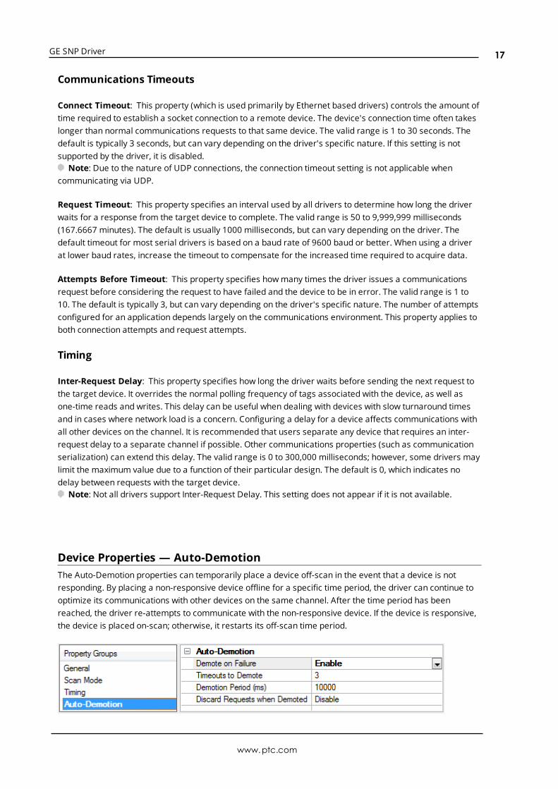
Device Properties — Auto-DemotionThe Auto-Demotion properties can temporarily place a device off-scan in the event that a device is notresponding. By placing a non-responsive device offline for a specific time period, the driver can continue tooptimize its communications with other devices on the same channel. After the time period has beenreached, the driver re-attempts to communicate with the non-responsive device. If the device is responsive,the device is placed on-scan; otherwise, it restarts its off-scan time period.
www.ptc.com
17

GE SNP Driver
Demote on Failure: When enabled, the device is automatically taken off-scan until it is responding again.Tip: Determine when a device is off-scan by monitoring its demoted state using the _AutoDemoted
system tag.
Timeouts to Demote: Specify howmany successive cycles of request timeouts and retries occur before thedevice is placed off-scan. The valid range is 1 to 30 successive failures. The default is 3.
Demotion Period: Indicate how long the device should be placed off-scan when the timeouts value isreached. During this period, no read requests are sent to the device and all data associated with the readrequests are set to bad quality. When this period expires, the driver places the device on-scan and allows foranother attempt at communications. The valid range is 100 to 3600000 milliseconds. The default is 10000milliseconds.
Discard Requests when Demoted: Select whether or not write requests should be attempted during theoff-scan period. Disable to always send write requests regardless of the demotion period. Enable to discardwrites; the server automatically fails any write request received from a client and does not post a messageto the Event Log.
Device Properties — Tag GenerationThe automatic tag database generation features make setting up an application a plug-and-play operation.Select communications drivers can be configured to automatically build a list of tags that correspond todevice-specific data. These automatically generated tags (which depend on the nature of the supportingdriver) can be browsed from the clients.
Not all devices and drivers support full automatic tag database generation and not all support the same datatypes. Consult the data types descriptions or the supported data type lists for each driver for specifics.
If the target device supports its own local tag database, the driver reads the device's tag information anduses the data to generate tags within the server. If the device does not natively support named tags, thedriver creates a list of tags based on driver-specific information. An example of these two conditions is asfollows:
1. If a data acquisition system supports its own local tag database, the communications driver uses thetag names found in the device to build the server's tags.
2. If an Ethernet I/O system supports detection of its own available I/Omodule types, thecommunications driver automatically generates tags in the server that are based on the types of I/Omodules plugged into the Ethernet I/O rack.
Note: Automatic tag database generation's mode of operation is completely configurable. For moreinformation, refer to the property descriptions below.
www.ptc.com
18

GE SNP Driver
On Property Change: If the device supports automatic tag generation when certain properties change, theOn Property Change option is shown. It is set to Yes by default, but it can be set toNo to control over whentag generation is performed. In this case, the Create tags actionmust be manually invoked to perform taggeneration.
On Device Startup: This property specifies when OPC tags are automatically generated. Descriptions of theoptions are as follows:
l Do Not Generate on Startup: This option prevents the driver from adding any OPC tags to the tagspace of the server. This is the default setting.
l Always Generate on Startup: This option causes the driver to evaluate the device for taginformation. It also adds tags to the tag space of the server every time the server is launched.
l Generate on First Startup: This option causes the driver to evaluate the target device for taginformation the first time the project is run. It also adds any OPC tags to the server tag space asneeded.
Note: When the option to automatically generate OPC tags is selected, any tags that are added to theserver's tag space must be saved with the project. Users can configure the project to automatically savefrom the Tools | Optionsmenu.
On Duplicate Tag: When automatic tag database generation is enabled, the server needs to know what todo with the tags that it may have previously added or with tags that have been added or modified after thecommunications driver since their original creation. This setting controls how the server handles OPC tagsthat were automatically generated and currently exist in the project. It also prevents automaticallygenerated tags from accumulating in the server.
For example, if a user changes the I/Omodules in the rack with the server configured to Always Generateon Startup, new tags would be added to the server every time the communications driver detected a newI/Omodule. If the old tags were not removed, many unused tags could accumulate in the server's tag space.The options are:
l Delete on Create: This option deletes any tags that were previously added to the tag space beforeany new tags are added. This is the default setting.
l Overwrite as Necessary: This option instructs the server to only remove the tags that thecommunications driver is replacing with new tags. Any tags that are not being overwritten remain inthe server's tag space.
l Do not Overwrite: This option prevents the server from removing any tags that were previouslygenerated or already existed in the server. The communications driver can only add tags that arecompletely new.
l Do not Overwrite, Log Error: This option has the same effect as the prior option, and also posts anerror message to the server's Event Log when a tag overwrite would have occurred.
Note: Removing OPC tags affects tags that have been automatically generated by thecommunications driver as well as any tags that have been added using names that match generatedtags. Users should avoid adding tags to the server using names that may match tags that areautomatically generated by the driver.
Parent Group: This property keeps automatically generated tags frommixing with tags that have beenenteredmanually by specifying a group to be used for automatically generated tags. The name of the groupcan be up to 256 characters. This parent group provides a root branch to which all automatically generatedtags are added.
www.ptc.com
19

GE SNP Driver
Allow Automatically Generated Subgroups: This property controls whether the server automaticallycreates subgroups for the automatically generated tags. This is the default setting. If disabled, the servergenerates the device's tags in a flat list without any grouping. In the server project, the resulting tags arenamed with the address value. For example, the tag names are not retained during the generation process.
Note: If, as the server is generating tags, a tag is assigned the same name as an existing tag, the systemautomatically increments to the next highest number so that the tag name is not duplicated. For example, ifthe generation process creates a tag named "AI22" that already exists, it creates the tag as "AI23" instead.
Create: Initiates the creation of automatically generated OPC tags. If the device's configuration has beenmodified, Create tags forces the driver to reevaluate the device for possible tag changes. Its ability to beaccessed from the System tags allows a client application to initiate tag database creation.
Note: Create tags is disabled if the Configuration edits a project offline.
Device Properties - Variable Import Settings
Descriptions of the properties are as follows:
l Variable Import File: This property is used to enter the exact location of the variable import file (.snfor .csv file extension) or Logic Developer variable import file (.txt or other file extension) from whichvariables will be imported. It is this file that will be used when Automatic Tag Database Generation isinstructed to create the tag database. All tags will be imported and expanded according to theirrespective data types.
l Display Descriptions: When enabled, this option will import tag descriptions. If necessary, adescription will be given to tags with long names stating the original tag name The default setting isenabled.
l Use Alias Data Type If Possible:When enabled, this option will use the data type assigned to analias tag in the import file. If the alias data type is incompatible with the source tag data type, thesource tag data type will be used instead. The default setting is disabled.
See Also: Automatic Tag Database Generation
Device Properties — Redundancy
www.ptc.com
20

GE SNP Driver
Redundancy is available with the Media-Level Redundancy Plug-In.Consult the website, a sales representative, or the user manual for more information.
www.ptc.com
21

GE SNP Driver
Data Types Description
DataType
Description
Boolean Single bit
Byte Unsigned 8 bit value
bit 0 is the low bitbit 7 is the high bit
Word Unsigned 16 bit value
bit 0 is the low bitbit 15 is the high bit
Short Signed 16 bit value
bit 0 is the low bitbit 14 is the high bitbit 15 is the sign bit
DWord Unsigned 32 bit value
bit 0 is the low bitbit 31 is the high bit
Long Signed 32 bit value
bit 0 is the low bitbit 30 is the high bitbit 31 is the sign bit
BCD Two byte packed BCD
Value range is 0-9999. Behavior is undefined for values beyond this range.
LBCD Four byte packed BCD
Value range is 0-99999999. Behavior is undefined for values beyond this range.
Float 32 bit floating point value.
The driver interprets two consecutive registers as a floating point value by making the secondregister the high word and the first register the low word.
String Null terminated ASCII string.
Support includes HiLo LoHi byte order selection.
Double 64 bit floating point value
www.ptc.com
22

GE SNP Driver
Automatic Tag Database GenerationThe GE SNP Driver generates its tags offline based on variables imported from a text file. It is offline in thesense that a connection to the device is not required to generate tags. The text file (variables to import) canoriginate from either one of the following applications:
l Cimplicity Machine Edition - Logic Developer
l VersaPro
There are two parts to Automatic Tag Database Generation: creating a variable import file from theapplication in use and generating tags based on the variable import file from the OPC server. Forinformation on creating variable import files, refer to "Importing VersaPro Tags" on page 59 or"Importing LogicDeveloper Tags" on page 63. For information on generating tags based on the importfile, refer to "Device Properties - Variable Import Settings" on page 20 and Tag Generation. It isrecommended that users become familiar with this second part before starting the first part.
Generating Tag Database While Preserving Previously Generated Tag DatabasesUnder certain circumstances, multiple imports into the server are required to import all tags of interest. Thisis the case with importing VersaPro System variables and non-System variables into the same OPC serverproject. In theTag Generation property group under Device Properties, click the property On Duplicate Tag.The options available are "Delete on create," "Overwrite as necessary," "Do not overwrite" and "Do notoverwrite, log error." After the first OPC server import/database creation is done, check that the action is setto "Do not overwrite" or "Do not overwrite, log error' for future imports. This will import tags without deletingor overwriting tags previously imported.
Tag HierarchyThe tags created via automatic tag generation follow a specific hierarchy. The root level groups (orsubgroup levels of the group specified in "Add generated tags to the following group") are determined bythe variable addresses referenced (such as R, G, M and so forth). For example, every variable that is ofaddress type "R" will be placed in a root level group called "R". Each array tag is provided in its own subgroupof the parent group. The name of the array subgroup provides a description of the array. For example, anarray R10[6] defined in the import file would have a subgroup name "R10_x". X signifies that dimension 1exists.
Tags in "R10_x" GroupTag Name Tag Address Comment
R10_x R10[6] Full array
R10_10 R10 Array element 1
R10_11 R11 Array element 2
R10_12 R12 Array element 3
R10_13 R13 Array element 4
R10_14 R14 Array element 5
R10_15 R15 Array element 6
Import File-to-Server Name ConversionsLeading Underscores, Percents, Pound, and Dollar Signs
www.ptc.com
23

GE SNP Driver
l Leading underscores (_) in tag names will be replaced withU_. This is required since the server doesnot accept tag/group names beginning with an underscore.
l Leading percents (%) in tag names will be replaced with P_. This is required since the server does notaccept tag/group names beginning with a percent sign.
l Leading pound signs (#) in tag names will be replaced with PD_. This is required since the serverdoes not accept tag/group names beginning with a pound sign.
l Leading dollar signs ($) in tag names will be replaced withD_. This is required since the server doesnot accept tag/group names beginning with a dollar sign.
Invalid Characters In NameThe only characters allowed in the server tag name are A-Z, a-z, 0-9 and underscore (_). As mentionedabove, a tag name cannot begin with an underscore. All other invalid characters encountered will beconverted to a sequence of characters that are valid. The table below lists the invalid character and thesequence of characters that it will be replaced with when encountered in the import file variable name.
Invalid Character Replaced With
$ D_
% P_
+ PL_
- M_
# PD_
@ A_
< L_
> G_
= E_
Long NamesThe GE SNP Driver is limited to 256 character group and tag names. Therefore, if a tag name exceeds 256characters, it must be clipped. Names are clipped as follows.
Non-Array
1. Determine a 5-digit Unique ID for this tag.
2. Given a tag name: ThisIsALongTagName...AndProbablyExceeds256
3. Clip tag at256: ThisIsALongTagName...AndProbablyEx
4. Room is made for the Unique ID: ThisIsALongTagName...AndProba#####
5. Insert this ID: ThisIsALongTagName...AndProba00000
Array
1. Determine a 5-digit Unique ID for this array.
2. Given an array tag name: ThisIsALongTagName...AndProbablyExceeds256_23_45_8
3. Clip tag at 256 while holding on to the element values: ThisIsALongTagName...AndPr_23_45_8
www.ptc.com
24

GE SNP Driver
4. Room is made for the Unique ID: ThisIsALongTagName...#####_23_45_8
5. Insert this ID: ThisIsALongTagName...00001_23_45_8
www.ptc.com
25

GE SNP Driver
Address DescriptionsAddress specifications vary depending on the model in use. Select a link from the following list to obtainspecific address information for the model of interest.
GE Micro311313331341350360731732771772781782GE OPENAdvanced Addressing
Note: Each topic contains tables that display the ranges that are supported by the driver for that model;however, the actual range may vary depending on the configuration of the device.
GE Micro AddressingThe default data types for dynamic tags are shown in bold.
Device Address Range Data Type* Access
Discrete Inputs I001 to I512I001 to I505 (every 8th bit)I001 to I497 (every 8th bit)
BooleanByteWord, Short, BCD
Read/Write
Discrete Outputs Q001 to Q512Q001 to Q505 (every 8th bit)Q001 to Q497 (every 8th bit)
BooleanByteWord, Short, BCD
Read/Write
Discrete Globals G0001 to G1280G0001 to G1273 (every 8th bit)G0001 to G1265 (every 8th bit)
BooleanByteWord, Short, BCD
Read/Write
Internal Coils M0001 to M1024M0001 to M1017 (every 8th bit)M0001 to M1009 (every 8th bit)
BooleanByteWord, Short, BCD
Read/Write
Temporary Coils T001 to T256T001 to T249 (every 8th bit)T001 to T241 (every 8th bit)
BooleanByteWord, Short, BCD
Read/Write
Status References
(Same for SA, SB, SC)
S01 to S32S01 to S25 (every 8th bit)S01 to S17 (every 8th bit)
BooleanByteWord, Short, BCD
Read Only
www.ptc.com
26
GE SNP Driver
Device Address Range Data Type* Access
Register References R0001 to R9999R0001 to R9998R0001 to R9996
Word, Short, BCDDWord, Long, LBCD, FloatDouble
Read/Write
Analog Inputs AI0001 to AI1024AI0001 to AI1023AI0001 to AI1021
Word, Short, BCDDWord, Long, LBCD, FloatDouble
Read/Write
Analog Outputs AQ0001 to AQ256AQ0001 to AQ255AQ0001 to AQ253
Word, Short, BCDDWord, Long, LBCD, FloatDouble
Read/Write
*Default data type of Boolean becomes Byte when an array specification is given.
Advanced AddressingDefault Data Type OverrideString Access to RegistersArray Support
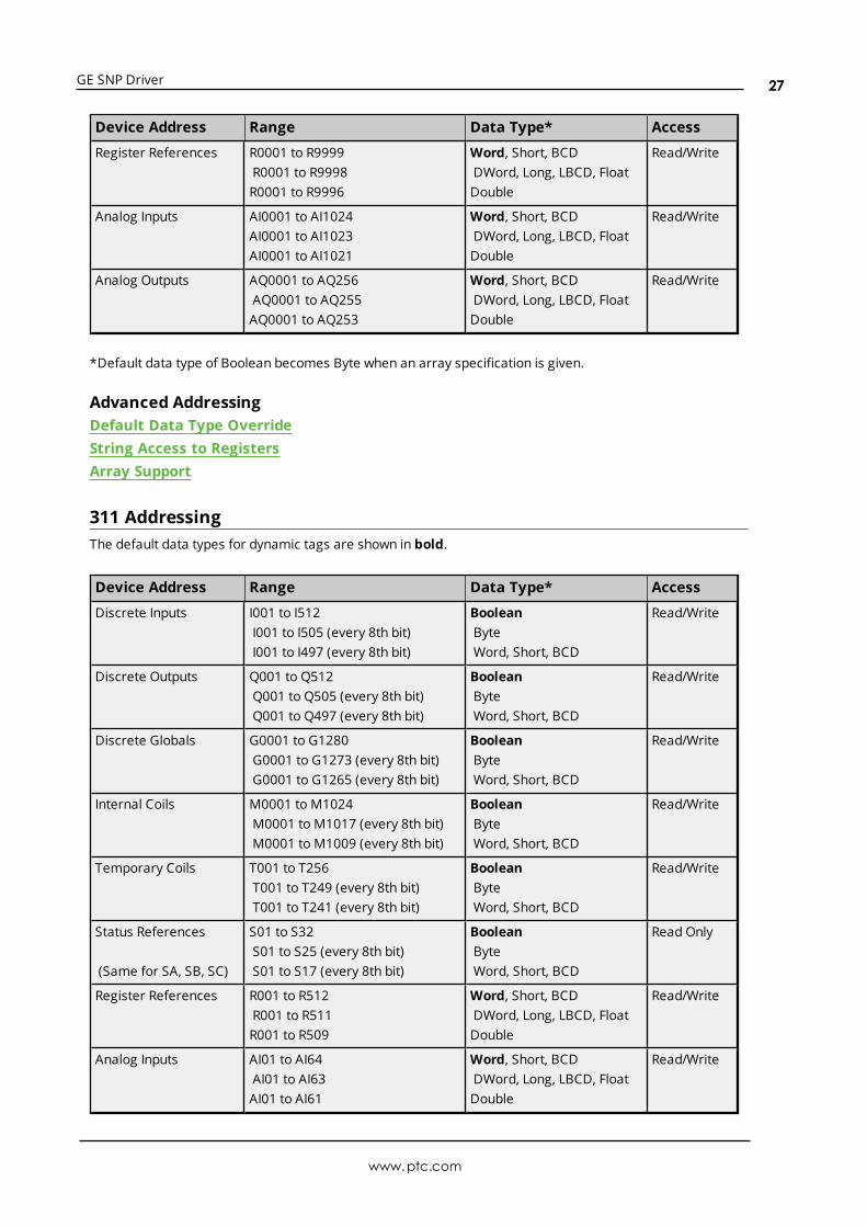
311 AddressingThe default data types for dynamic tags are shown in bold.
Device Address Range Data Type* Access
Discrete Inputs I001 to I512I001 to I505 (every 8th bit)I001 to I497 (every 8th bit)
BooleanByteWord, Short, BCD
Read/Write
Discrete Outputs Q001 to Q512Q001 to Q505 (every 8th bit)Q001 to Q497 (every 8th bit)
BooleanByteWord, Short, BCD
Read/Write
Discrete Globals G0001 to G1280G0001 to G1273 (every 8th bit)G0001 to G1265 (every 8th bit)
BooleanByteWord, Short, BCD
Read/Write
Internal Coils M0001 to M1024M0001 to M1017 (every 8th bit)M0001 to M1009 (every 8th bit)
BooleanByteWord, Short, BCD
Read/Write
Temporary Coils T001 to T256T001 to T249 (every 8th bit)T001 to T241 (every 8th bit)
BooleanByteWord, Short, BCD
Read/Write
Status References
(Same for SA, SB, SC)
S01 to S32S01 to S25 (every 8th bit)S01 to S17 (every 8th bit)
BooleanByteWord, Short, BCD
Read Only
Register References R001 to R512R001 to R511R001 to R509
Word, Short, BCDDWord, Long, LBCD, FloatDouble
Read/Write
Analog Inputs AI01 to AI64AI01 to AI63AI01 to AI61
Word, Short, BCDDWord, Long, LBCD, FloatDouble
Read/Write
www.ptc.com
27

GE SNP Driver
Device Address Range Data Type* Access
Analog Outputs AQ001 to AQ032AQ001 to AQ031AQ001 to AQ029
Word, Short, BCDDWord, Long, LBCD, FloatDouble
Read/Write
*Default data type of Boolean becomes Byte when an array specification is given.
Advanced AddressingDefault Data Type OverrideString Access to RegistersArray Support
313 AddressingThe default data types for dynamic tags are shown in bold.
Device Address Range Data Type* Access
Discrete Inputs I001 to I512I001 to I505 (every 8th bit)I001 to I497 (every 8th bit)
BooleanByteWord, Short, BCD
Read/Write
Discrete Outputs Q001 to Q512Q001 to Q505 (every 8th bit)Q001 to Q497 (every 8th bit)
BooleanByteWord, Short, BCD
Read/Write
Discrete Globals G0001 to G1280G0001 to G1273 (every 8th bit)G0001 to G1265 (every 8th bit)
BooleanByteWord, Short, BCD
Read/Write
Internal Coils M0001 to M1024M0001 to M1017 (every 8th bit)M0001 to M1009 (every 8th bit)
BooleanByteWord, Short, BCD
Read/Write
Temporary Coils T001 to T256T001 to T249 (every 8th bit)T001 to T241 (every 8th bit)
BooleanByteWord, Short, BCD
Read/Write
Status References
(Same for SA, SB, SC)
S01 to S32S01 to S25 (every 8th bit)S01 to S17 (every 8th bit)
BooleanByteWord, Short, BCD
Read Only
Register References R001 to R1024R001 to R1023R001 to R1021
Word, Short, BCDDWord, Long, LBCD, FloatDouble
Read/Write
Analog Inputs AI01 to AI64AI01 to AI63AI01 to AI61
Word, Short, BCDDWord, Long, LBCD, FloatDouble
Read/Write
Analog Outputs AQ001 to AQ032AQ001 to AQ031AQ001 to AQ029
Word, Short, BCDDWord, Long, LBCD, FloatDouble
Read/Write
*Default data type of Boolean becomes Byte when an array specification is given.
www.ptc.com
28

GE SNP Driver
Advanced AddressingDefault Data Type OverrideString Access to RegistersArray Support
331 AddressingThe default data types for dynamic tags are shown in bold.
Device Address Range Data Type* Access
Discrete Inputs I001 to I512I001 to I505 (every 8th bit)I001 to I497 (every 8th bit)
BooleanByteWord, Short, BCD
Read/Write
Discrete Outputs Q001 to Q512Q001 to Q505 (every 8th bit)Q001 to Q497 (every 8th bit)
BooleanByteWord, Short, BCD
Read/Write
Discrete Globals G0001 to G1280G0001 to G1273 (every 8th bit)G0001 to G1265 (every 8th bit)
BooleanByteWord, Short, BCD
Read/Write
Internal Coils M0001 to M1024M0001 to M1017 (every 8th bit)M0001 to M1009 (every 8th bit)
BooleanByteWord, Short, BCD
Read/Write
Temporary Coils T001 to T256T001 to T249 (every 8th bit)T001 to T241 (every 8th bit)
BooleanByteWord, Short, BCD
Read/Write
Status References
(Same for SA, SB, SC)
S01 to S32S01 to S25 (every 8th bit)S01 to S17 (every 8th bit)
BooleanByteWord, Short, BCD
Read Only
Register References R0001 to R2048R0001 to R2047R0001 to R2045
Word, Short, BCDDWord, Long, LBCD, FloatDouble
Read/Write
Analog Inputs AI001 to AI128AI001 to AI127AI001 to AI125
Word, Short, BCDDWord, Long, LBCD, FloatDouble
Read/Write
Analog Outputs AQ01 to AQ64AQ01 to AQ63AQ01 to AQ61
Word, Short, BCDDWord, Long, LBCD, FloatDouble
Read/Write
*Default data type of Boolean becomes Byte when an array specification is given.
Advanced AddressingDefault Data Type OverrideString Access to RegistersArray Support
341 AddressingThe default data types for dynamic tags are shown in bold.
www.ptc.com
29

GE SNP Driver
Device Address Range Data Type* Access
Discrete Inputs I001 to I512I001 to I505 (every 8th bit)I001 to I497 (every 8th bit)
BooleanByteWord, Short, BCD
Read/Write
Discrete Outputs Q001 to Q512Q001 to Q505 (every 8th bit)Q001 to Q497 (every 8th bit)
BooleanByteWord, Short, BCD
Read/Write
Discrete Globals G0001 to G1280G0001 to G1273 (every 8th bit)G0001 to G1265 (every 8th bit)
BooleanByteWord, Short, BCD
Read/Write
Internal Coils M0001 to M1024M0001 to M1017 (every 8th bit)M0001 to M1009 (every 8th bit)
BooleanByteWord, Short, BCD
Read/Write
Temporary Coils T001 to T256T001 to T249 (every 8th bit)T001 to T241 (every 8th bit)
BooleanByteWord, Short, BCD
Read/Write
Status References
(Same for SA, SB, SC)
S01 to S32S01 to S25 (every 8th bit)S01 to S17 (every 8th bit)
BooleanByteWord, Short, BCD
Read Only
Register References R0001 to R9999R0001 to R9998R0001 to R9996
Word, Short, BCDDWord, Long, LBCD, FloatDouble
Read/Write
Analog Inputs AI0001 to AI1024AI0001 to AI1023AI0001 to AI1021
Word, Short, BCDDWord, Long, LBCD, FloatDouble
Read/Write
Analog Outputs AQ0001 to AQ256AQ0001 to AQ255AQ0001 to AQ253
Word, Short, BCDDWord, Long, LBCD, FloatDouble
Read/Write
*Default data type of Boolean becomes Byte when an array specification is given.
Advanced AddressingDefault Data Type OverrideString Access to RegistersArray Support
350 AddressingThe default data types for dynamic tags are shown in bold.
Device Address Range Data Type* Access
Discrete Inputs I0001 to I2048I0001 to I2041 (every 8th bit)I0001 to I2033 (every 8th bit)
BooleanByteWord, Short, BCD
Read/Write
Discrete Outputs Q0001 to Q2048Q0001 to Q2041 (every 8th bit)
BooleanByte
Read/Write
www.ptc.com
30

GE SNP Driver
Device Address Range Data Type* Access
Q0001 to Q2033 (every 8th bit) Word, Short, BCD
Discrete Globals G0001 to G1280G0001 to G1273 (every 8th bit)G0001 to G1265 (every 8th bit)
BooleanByteWord, Short, BCD
Read/Write
Internal Coils M0001 to M4096M0001 to M4089 (every 8th bit)M0001 to M4081 (every 8th bit)
BooleanByteWord, Short, BCD
Read/Write
Temporary Coils T001 to T256T001 to T249 (every 8th bit)T001 to T241 (every 8th bit)
BooleanByteWord, Short, BCD
Read/Write
Status References
(Same for SA, SB, SC)
S01 to S32S01 to S25 (every 8th bit)S01 to S17 (every 8th bit)
BooleanByteWord, Short, BCD
Read Only
Register References R0001 to R9999R0001 to R9998R0001 to R9996
Word, Short, BCDDWord, Long, LBCD, FloatDouble
Read/Write
Analog Inputs AI0001 to AI2048AI0001 to AI2047AI0001 to AI2045
Word, Short, BCDDWord, Long, LBCD, FloatDouble
Read/Write
Analog Outputs AQ001 to AQ512AQ001 to AQ511AQ001 to AQ509
Word, Short, BCDDWord, Long, LBCD, FloatDouble
Read/Write
*Default data type of Boolean becomes Byte when an array specification is given.
Advanced AddressingDefault Data Type OverrideString Access to RegistersArray Support
360 AddressingThe default data types for dynamic tags are shown in bold.
Device Address Range Data Type* Access
Discrete Inputs I0001 to I2048I0001 to I2041 (every 8th bit)I0001 to I2033 (every 8th bit)
BooleanByteWord, Short, BCD
Read/Write
Discrete Outputs Q0001 to Q2048Q0001 to Q2041 (every 8th bit)Q0001 to Q2033 (every 8th bit)
BooleanByteWord, Short, BCD
Read/Write
Discrete Globals G0001 to G1280G0001 to G1273 (every 8th bit)G0001 to G1265 (every 8th bit)
BooleanByteWord, Short, BCD
Read/Write
Internal Coils M0001 to M4096M0001 to M4089 (every 8th bit)
BooleanByte
Read/Write
www.ptc.com
31

GE SNP Driver
Device Address Range Data Type* Access
M0001 to M4081 (every 8th bit) Word, Short, BCD
Temporary Coils T001 to T256T001 to T249 (every 8th bit)T001 to T241 (every 8th bit)
BooleanByteWord, Short, BCD
Read/Write
Status References
(Same for SA, SB, SC)
S01 to S32S01 to S25 (every 8th bit)S01 to S17 (every 8th bit)
BooleanByteWord, Short, BCD
Read Only
Register References R00001 to R32768R00001 to R32767R00001 to R32765
Word, Short, BCDDWord, Long, LBCD, FloatDouble
Read/Write
Analog Inputs AI0001 to AI2048AI0001 to AI2047AI0001 to AI2045
Word, Short, BCDDWord, Long, LBCD, FloatDouble
Read/Write
Analog Outputs AQ001 to AQ512AQ001 to AQ511AQ001 to AQ509
Word, Short, BCDDWord, Long, LBCD, FloatDouble
Read/Write
*Default data type of Boolean becomes Byte when an array specification is given.
Advanced AddressingDefault Data Type OverrideString Access to RegistersArray Support
731 AddressingThe default data types for dynamic tags are shown in bold.
Device Address Range Data Type* Access
Discrete Inputs I001 to I512I001 to I505 (every 8th bit)I001 to I497 (every 8th bit)
BooleanByteWord, Short, BCD
Read/Write
Discrete Outputs Q001 to Q512Q001 to Q505 (every 8th bit)Q001 to Q497 (every 8th bit)
BooleanByteWord, Short, BCD
Read/Write
Discrete Globals G0001 to G1280G0001 to G1273 (every 8th bit)G0001 to G1265 (every 8th bit)
BooleanByteWord, Short, BCD
Read/Write
Internal Coils M0001 to M2048M0001 to M2041 (every 8th bit)M0001 to M2033 (every 8th bit)
BooleanByteWord, Short, BCD
Read/Write
Temporary Coils T001 to T256T001 to T249 (every 8th bit)T001 to T241 (every 8th bit)
BooleanByteWord, Short, BCD
Read/Write
Status References S001 to S128S001 to S121 (every 8th bit)
BooleanByte
Read Only
www.ptc.com
32

GE SNP Driver
Device Address Range Data Type* Access
(Same for SA, SB, SC) S001 to S113 (every 8th bit) Word, Short, BCD
Register References R00001 to R16384R00001 to R16383R00001 to R16381
Word, Short, BCDDWord, Long, LBCD, FloatDouble
Read/Write
Analog Inputs AI0001 to AI8192AI0001 to AI8191AI0001 to AI8189
Word, Short, BCDDWord, Long, LBCD, FloatDouble
Read/Write
Analog Outputs AQ0001 to AQ8192AQ0001 to AQ8191AQ0001 to AQ8189
Word, Short, BCDDWord, Long, LBCD, FloatDouble
Read/Write
*Default data type of Boolean becomes Byte when an array specification is given.
Advanced AddressingDefault Data Type OverrideString Access to RegistersArray Support
732 AddressingThe default data types for dynamic tags are shown in bold.
Device Address Range Data Type* Access
Discrete Inputs I001 to I512I001 to I505 (every 8th bit)I001 to I497 (every 8th bit)
BooleanByteWord, Short, BCD
Read/Write
Discrete Outputs Q001 to Q512Q001 to Q505 (every 8th bit)Q001 to Q497 (every 8th bit)
BooleanByteWord, Short, BCD
Read/Write
Discrete Globals G0001 to G1280G0001 to G1273 (every 8th bit)G0001 to G1265 (every 8th bit)
BooleanByteWord, Short, BCD
Read/Write
Internal Coils M0001 to M2048M0001 to M2041 (every 8th bit)M0001 to M2033 (every 8th bit)
BooleanByteWord, Short, BCD
Read/Write
Temporary Coils T001 to T256T001 to T249 (every 8th bit)T001 to T241 (every 8th bit)
BooleanByteWord, Short, BCD
Read/Write
Status References
(Same for SA, SB, SC)
S001 to S128S001 to S121 (every 8th bit)S001 to S113 (every 8th bit)
BooleanByteWord, Short, BCD
Read Only
Register References R00001 to R16384R00001 to R16383R00001 to R16381
Word, Short, BCDDWord, Long, LBCD, FloatDouble
Read/Write
Analog Inputs AI0001 to AI8192AI0001 to AI8191
Word, Short, BCDDWord, Long, LBCD, Float
Read/Write
www.ptc.com
33

GE SNP Driver
Device Address Range Data Type* Access
AI0001 to AI8189 Double
Analog Outputs AQ0001 to AQ8192AQ0001 to AQ8191AQ0001 to AQ8189
Word, Short, BCDDWord, Long, LBCD, FloatDouble
Read/Write
*Default data type of Boolean becomes Byte when an array specification is given.
Advanced AddressingDefault Data Type OverrideString Access to RegistersArray Support
771 AddressingThe default data types for dynamic tags are shown in bold.
Device Address Range Data Type* Access
Discrete Inputs I0001 to I2048I0001 to I2041 (every 8th bit)I0001 to I2033 (every 8th bit)
BooleanByteWord, Short, BCD
Read/Write
Discrete Outputs Q0001 to Q2048Q0001 to Q2041 (every 8th bit)Q0001 to Q2033 (every 8th bit)
BooleanByteWord, Short, BCD
Read/Write
Discrete Globals G0001 to G7680G0001 to G7673 (every 8th bit)G0001 to G7665 (every 8th bit)
BooleanByteWord, Short, BCD
Read/Write
Internal Coils M0001 to M4096M0001 to M4089 (every 8th bit)M0001 to M4081 (every 8th bit)
BooleanByteWord, Short, BCD
Read/Write
Temporary Coils T001 to T256T001 to T249 (every 8th bit)T001 to T241 (every 8th bit)
BooleanByteWord, Short, BCD
Read/Write
Status References
(Same for SA, SB, SC)
S001 to S128S001 to S121 (every 8th bit)S001 to S113 (every 8th bit)
BooleanByteWord, Short, BCD
Read Only
Register References R00001 to R16384R00001 to R16383R00001 to R16381
Word, Short, BCDDWord, Long, LBCD, FloatDouble
Read/Write
Analog Inputs AI0001 to AI8192AI0001 to AI8191AI0001 to AI8189
Word, Short, BCDDWord, Long, LBCD, FloatDouble
Read/Write
Analog Outputs AQ0001 to AQ8192AQ0001 to AQ8191AQ0001 to AQ8189
Word, Short, BCDDWord, Long, LBCD, FloatDouble
Read/Write
*Default data type of Boolean becomes Byte when an array specification is given.
www.ptc.com
34

GE SNP Driver
Advanced AddressingDefault Data Type OverrideString Access to RegistersArray Support
772 AddressingThe default data types for dynamic tags are shown in bold.
Device Address Range Data Type* Access
Discrete Inputs I0001 to I2048I0001 to I2041 (every 8th bit)I0001 to I2033 (every 8th bit)
BooleanByteWord, Short, BCD
Read/Write
Discrete Outputs Q0001 to Q2048Q0001 to Q2041 (every 8th bit)Q0001 to Q2033 (every 8th bit)
BooleanByteWord, Short, BCD
Read/Write
Discrete Globals G0001 to G7680G0001 to G7673 (every 8th bit)G0001 to G7665 (every 8th bit)
BooleanByteWord, Short, BCD
Read/Write
Internal Coils M0001 to M4096M0001 to M4089 (every 8th bit)M0001 to M4081 (every 8th bit)
BooleanByteWord, Short, BCD
Read/Write
Temporary Coils T001 to T256T001 to T249 (every 8th bit)T001 to T241 (every 8th bit)
BooleanByteWord, Short, BCD
Read/Write
Status References
(Same for SA, SB, SC)
S001 to S128S001 to S121 (every 8th bit)S001 to S113 (every 8th bit)
BooleanByteWord, Short, BCD
Read Only
Register References R00001 to R16384R00001 to R16383R00001 to R16381
Word, Short, BCDDWord, Long, LBCD, FloatDouble
Read/Write
Analog Inputs AI0001 to AI8192AI0001 to AI8191AI0001 to AI8189
Word, Short, BCDDWord, Long, LBCD, FloatDouble
Read/Write
Analog Outputs AQ0001 to AQ8192AQ0001 to AQ8191AQ0001 to AQ8189
Word, Short, BCDDWord, Long, LBCD, FloatDouble
Read/Write
*Default data type of Boolean becomes Byte when an array specification is given.
Advanced AddressingDefault Data Type OverrideString Access to RegistersArray Support
www.ptc.com
35

GE SNP Driver
781 AddressingThe default data types for dynamic tags are shown in bold.
Device Address Range Data Type* Access
Discrete Inputs I00001 to I12288I00001 to I12281 (every 8th bit)I00001 to I12273 (every 8th bit)
BooleanByteWord, Short, BCD
Read/Write
Discrete Outputs Q00001 to Q12288Q00001 to Q12281 (every 8th bit)Q00001 to Q12273 (every 8th bit)
BooleanByteWord, Short, BCD
Read/Write
Discrete Globals G0001 to G7680G0001 to G7673 (every 8th bit)G0001 to G7665 (every 8th bit)
BooleanByteWord, Short, BCD
Read/Write
Internal Coils M00001 to M12288M00001 to M12281 (every 8th bit)M00001 to M12273 (every 8th bit)
BooleanByteWord, Short, BCD
Read/Write
Temporary Coils T001 to T256T001 to T249 (every 8th bit)T001 to T241 (every 8th bit)
BooleanByteWord, Short, BCD
Read/Write
Status References
(Same for SA, SB, SC)
S001 to S128S001 to S121 (every 8th bit)S001 to S113 (every 8th bit)
BooleanByteWord, Short, BCD
Read Only
Register References R00001 to R16384R00001 to R16383R00001 to R16381
Word, Short, BCDDWord, Long, LBCD, FloatDouble
Read/Write
Analog Inputs AI0001 to AI8192AI0001 to AI8191AI0001 to AI8189
Word, Short, BCDDWord, Long, LBCD, FloatDouble
Read/Write
Analog Outputs AQ0001 to AQ8192AQ0001 to AQ8191AQ0001 to AQ8189
Word, Short, BCDDWord, Long, LBCD, FloatDouble
Read/Write
*Default data type of Boolean becomes Byte when an array specification is given.
Advanced AddressingDefault Data Type OverrideString Access to RegistersArray Support
782 AddressingThe default data types for dynamic tags are shown in bold.
Device Address Range Data Type* Access
Discrete Inputs I00001 to I12288I00001 to I12281 (every 8th bit)I00001 to I12273 (every 8th bit)
BooleanByteWord, Short, BCD
Read/Write
www.ptc.com
36

GE SNP Driver
Device Address Range Data Type* Access
Discrete Outputs Q00001 to Q12288Q00001 to Q12281 (every 8th bit)Q00001 to Q12273 (every 8th bit)
BooleanByteWord, Short, BCD
Read/Write
Discrete Globals G0001 to G7680G0001 to G7673 (every 8th bit)G0001 to G7665 (every 8th bit)
BooleanByteWord, Short, BCD
Read/Write
Internal Coils M00001 to M12288M00001 to M12281 (every 8th bit)M00001 to M12273 (every 8th bit)
BooleanByteWord, Short, BCD
Read/Write
Temporary Coils T001 to T256T001 to T249 (every 8th bit)T001 to T241 (every 8th bit)
BooleanByteWord, Short, BCD
Read/Write
Status References
(Same for SA, SB, SC)
S001 to S128S001 to S121 (every 8th bit)S001 to S113 (every 8th bit)
BooleanByteWord, Short, BCD
Read Only
Register References R00001 to R16384R00001 to R16383R00001 to R16381
Word, Short, BCDDWord, Long, LBCD, FloatDouble
Read/Write
Analog Inputs AI0001 to AI8192AI0001 to AI8191AI0001 to AI8189
Word, Short, BCDDWord, Long, LBCD, FloatDouble
Read/Write
Analog Outputs AQ0001 to AQ8192AQ0001 to AQ8191AQ0001 to AQ8189
Word, Short, BCDDWord, Long, LBCD, FloatDouble
Read/Write
*Default data type of Boolean becomes Byte when an array specification is given.
Advanced AddressingDefault Data Type OverrideString Access to RegistersArray Support
GE OPEN AddressingThe GE OPEN model selection has been provided to supply support for any GE SNP compatible device that isnot currently listed in the standardmodel selectionmenu. The ranges of data for each data type have beenexpanded to allow a wide range of GE PLCs to be addressed. Although the address ranges shown here mayexceed the specific PLC's capability, the driver will respect all messages from the PLC regarding memoryrange limits.
The default data types for dynamic tags are shown in bold.
Device Address Range Data Type* Access
Discrete Inputs I0001 to I32768I0001 to I32761 (every 8th bit)I0001 to I32753 (every 8th bit)
BooleanByteWord, Short, BCD
Read/Write
www.ptc.com
37

GE SNP Driver
Device Address Range Data Type* Access
Discrete Outputs Q00001 to Q32768Q00001 to Q32761 (every 8th bit)Q00001 to Q32753 (every 8th bit)
BooleanByteWord, Short, BCD
Read/Write
Discrete Globals G00001 to G32768G00001 to G32761 (every 8th bit)G00001 to G32753 (every 8th bit)
BooleanByteWord, Short, BCD
Read/Write
Internal Coils M00001 to M32768M00001 to M32761 (every 8th bit)M00001 to M32753 (every 8th bit)
BooleanByteWord, Short, BCD
Read/Write
Temporary Coils T00001 to T32768T00001 to T32761 (every 8th bit)T00001 to T32753 (every 8th bit)
BooleanByteWord, Short, BCD
Read/Write
Status References
(Same for SA, SB, SC)
S00001 to S32768S00001 to S32761 (every 8th bit)S00001 to S32753 (every 8th bit)
BooleanByteWord, Short, BCD
Read Only
Register References R00001 to R32768R00001 to R32767R00001 to R32765
Word, Short, BCDDWord, Long, LBCD, FloatDouble
Read/Write
Analog Inputs AI00001 to AI32768AI00001 to AI32767AI00001 to AI32765
Word, Short, BCDDWord, Long, LBCD, FloatDouble
Read/Write
Analog Outputs AQ00001 to AQ32768AQ00001 to AQ32767AQ00001 to AQ32765
Word, Short, BCDDWord, Long, LBCD, FloatDouble
Read/Write
*Default data type of Boolean becomes Byte when an array specification is given.
Advanced AddressingDefault Data Type OverrideString Access to RegistersArray Support
Advanced AddressingDefault Data Type OverrideThe default data types for each device type are shown in the table below. These defaults can be overriddenby appending data type indicators to the device address. The possible data type indicators are as follows.
Indicators Data type
F Float
S Short
L Long
M String
(BCD) BCD
www.ptc.com
38

GE SNP Driver
ExamplesAddress Description
R100 F Access R100 as a floating point value
R300 L Access R300 as a long
R400–R410 M Access R400-R410 as a string with a length of 22 bytes. (LoHi byte order is assumed.)
Note: There must be a space between the register number and the data type indicator.
String Access to RegistersRegister space can be accessed as string data by appending the "M" data type indicator. The length of thestring is based on how the device address reference is entered. Each register addressed can contain twocharacters. The byte order of characters in registers can be specified by appending an optional "H" for HiLoor "L" for LoHi after the "M" data indicator. If no byte order is specified, LoHi order is assumed.
ExamplesAddress Description
R100-R150 M Access Register R100 as string with a length of 102 bytes. (LoHi byte order is assumed.)
R400 M Access Register R400 as a string with a length of 4 bytes. (LoHi byte order is assumed.)
R405-R405 M Access Register R405 as a string with a length of 2 bytes. (LoHi byte order is assumed.)
R100-R150 MH
Access Register R100 as string with a length of 102 bytes. HiLo byte order is explicitlyspecified.
R100-R150 ML
Access Register R100 as string with a length of 102 bytes. LoHi byte order is explicitlyspecified.
Note: The maximum string length is 128 bytes. For HiLo byte ordering, the string "AB" would be stored in aregister as 0x4142. For LoHi byte ordering, the string "AB" would be stored in a register as 0x4241. Theremust be a space between the "M" data type indicator and the byte order indicator.
Array SupportAn array is a collection of contiguous elements of a given data type. The maximum array size is 16 Doubles,32 DWords (Longs, Floats), 64 Words (Shorts), or 128 Bytes for a total of 1024 bits. The following data typessupport arrays: Byte, Word, Short, DWord, Long, Float, and Double.
ExamplesAddress Address Breakdown
G1 [4] includes the followingbyte addresses*
G1,G9,G17,G25
1 row implied = 4 bytes4 x 8 (byte) = 32 total bits
R16 [3][4] includes the followingword addresses:
R16,R17,R18,R19R20,R21,R22,R23R24,R25,R26,R27
3 rows x 4 columns = 12 words12 x 16 (word) = 192 total bits
P10 [5] includes the following P10, P11, P12, P13, P14
www.ptc.com
39
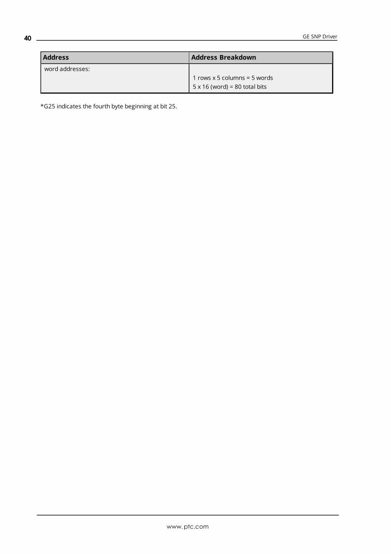
GE SNP Driver
Address Address Breakdown
word addresses:1 rows x 5 columns = 5 words5 x 16 (word) = 80 total bits
*G25 indicates the fourth byte beginning at bit 25.
www.ptc.com
40

GE SNP Driver
Error DescriptionsThe following messages may be generated. Click on the link for a description of the message.
Address ValidationMissing addressDevice address '<address>' contains a syntax errorAddress '<address>' is out of range for the specified device or registerDevice address '<address>' is not supported by model '<model name>'Data Type '<type>' is not valid for device address '<address>'Device address '<address>' is Read OnlyArray size is out of range for address '<address>'Array support is not available for the specified address: '<address>'
Serial CommunicationsCOMn does not existError opening COMnCOMn is in use by another applicationUnable to set comm parameters on COMnCommunications error on '<channel name>' [<error mask>]
Device Status MessagesDevice '<device name>' is not respondingUnable to write to '<address>' on device '<device name>'
Device-Specific MessagesInvalid tag in block starting at <address> on device <device name>. Block deactivated
Write Error MessagesUnable to write to tag '<tag address>' on device '<device name>'. The service requestedis either not defined or not supportedUnable to write to tag '<tag address>' on device '<device name>'. The user does not havesufficient privileges to process the request. Minor status error code = '<hexadecimalerror code>'Unable to write to tag '<tag address>' on device '<device name>'. The CPU has received amessage that is out of orderUnable to write to tag '<tag address>' on device '<device name>'. Service request error.Minor status error code = '<hexadecimal error code>'Unable to write to tag '<tag address>' on device '<device name>'. Service requestmailbox type is either undefined or unexpectedUnable to write to tag '<tag address>' on device '<device name>'. The PLC CPU's servicerequest queue is full: please wait a minimum of 10 ms before sending another servicerequestUnable to write to tag '<tag address>' on device '<device name>'. A framing error hasoccurred
www.ptc.com
41

GE SNP Driver
Unable to write to tag '<tag address>' on device '<device name>'. Device returned majorerror code '<hexadecimal error code>' and minor error code '<hexadecimal error code>'
Blocked Read Error MessagesUnable to read '<number of bytes>' bytes starting at address '<tag address>' on device'<device name>'. The service requested is either not defined or not supportedUnable to read '<number of bytes>' bytes starting at address '<tag address>' on device'<device name>'. The user does not have sufficient privileges to process the request.Minor status error code = '<hexadecimal error code>'Unable to read '<number of bytes>' bytes starting at address '<tag address>' on device'<device name>'. The CPU has received a message that is out of orderUnable to read '<number of bytes>' bytes starting at address '<tag address>' on device'<device name>'. Service request error. Minor status error code = '<hexadecimal errorcode>'Unable to read '<number of bytes>' bytes starting at address '<tag address>' on device'<device name>'. Service request mailbox type is either undefined or unexpectedUnable to read '<number of bytes>' bytes starting at address '<tag address>' on device'<device name>'. The PLC CPU's service request queue is full: please wait a minimum of10 ms before sending another service requestUnable to read '<byte count>' bytes starting at address '<start tag>' on device '<devicename>'. A framing error has occurredUnable to read '<number of bytes>' bytes starting at address '<tag address>' on device'<device name>'. Device returned major error code '<hexadecimal error code>' and minorerror code '<hexadecimal error code>'
Non-Blocked Error MessagesUnable to read tag '<tag address>' on device '<device name>'. The service requested iseither not defined or not supportedUnable to read tag '<tag address>' on device '<device name>'. The user does not havesufficient privileges to process the request. Minor status error code = '<hexadecimalerror code>'Unable to read tag '<tag address>' on device '<device name>'. The CPU has received amessage that is out of orderUnable to read tag '<tag address>' on device '<device name>'. Service request error.Minor status error code = '<hexadecimal error code>'Unable to read tag '<tag address>' on device '<device name>'. Service request mailboxtype is either undefined or unexpectedUnable to read tag '<tag address>' on device '<device name>'. The PLC CPU's servicerequest queue is full: please wait a minimum of 10 ms before sending another servicerequestUnable to read tag '<tag address>' on device '<device name>'. A framing error hasoccurredUnable to read tag '<tag address>' on device '<device name>'. Device returned majorerror code '<hexadecimal error code>' and minor error code '<hexadecimal error code>'
Automatic Tag Database Generation Messages
www.ptc.com
42

GE SNP Driver
Unable to generate a tag database for device <device name>. Reason: Low memoryresourcesUnable to generate a tag database for device <device name>. Reason: Import file isinvalid or corruptDatabase Error: Tag '<orig. tag name>' exceeds 256 characters. Tag renamed to '<newtag name>'Database Error: Array tags '<orig. tag name><dimensions>' exceed 256 characters. Tagsrenamed to '<new tag name><dimensions>'Database Error: Data type '<type>' for tag '<tag name>' not found in import file. Settingto defaultDatabase Error: Data type '<type>' for tag '<tag name>' is currently not supported. Tagnot createdDatabase Error: Logic Developer Variable Arrays are currently not supported. Array Tag(s) '<array tag name>' not createdDatabase Error: No Reference Address found for tag '<tag name>' in import file. Tag notcreatedDatabase Error: Only variables with Data Source '<data source name>' are imported.Data Source '<data source name>' is not supported. Tag '<tag name>' not createdDatabase Error: Data type '<type>' arrays are currently not supported. Tag '<array tagname>' not created
Missing addressError Type:Warning
Possible Cause:A tag address that has been specified statically has no length.
Solution:Re-enter the address in the client application.
Device address '<address>' contains a syntax errorError Type:Warning
Possible Cause:A tag address that has been specified statically via DDE contains one or more invalid characters.
Solution:Re-enter the address in the client application.
Address '<address>' is out of range for the specified device or registerError Type:Warning
www.ptc.com
43

GE SNP Driver
Possible Cause:A tag address that has been specified statically via DDE references a location that is beyond the range ofsupported locations for the device.
Solution:Verify the address is correct; if it is not, re-enter it in the client application.
Device address '<address>' is not supported by model '<model name>'Error Type:Warning
Possible Cause:A tag address that has been specified statically references a location that is valid for the communicationsprotocol but not supported by the target device.
Solution:Verify that the address is correct; if it is not, re-enter it in the client application. Also verify that the selectedmodel name for the device is correct.
Data Type '<type>' is not valid for device address '<address>'Error Type:Warning
Possible Cause:A tag address that has been specified statically has been assigned an invalid data type.
Solution:Modify the requested data type in the client application.
Device address '<address>' is Read OnlyError Type:Warning
Possible Cause:A tag address that has been specified statically has a requested access mode that is not compatible withwhat the device supports for that address.
Solution:Change the access mode in the client application.
Array size is out of range for address '<address>'Error Type:Warning
Possible Cause:A tag address that has been specified statically is requesting an array size that is too large for the addresstype or block size of the driver.
www.ptc.com
44

GE SNP Driver
Solution:Re-enter the address in the client application to specify a smaller value for the array or a different startingpoint.
Array support is not available for the specified address: '<address>'Error Type:Warning
Possible Cause:A tag address that has been specified statically contains an array reference for an address type that doesn'tsupport arrays.
Solution:Re-enter the address in the client application to remove the array reference or correct the address type.
COMn does not existError Type:Fatal
Possible Cause:The specified COM port is not present on the target computer.
Solution:Verify that the proper COM port has been selected.
Error opening COMnError Type:Fatal
Possible Cause:The specified COM port could not be opened due an internal hardware or software problem on the targetcomputer.
Solution:Verify that the COM port is functional andmay be accessed by other Windows applications.
COMn is in use by another applicationError Type:Fatal
Possible Cause:The serial port assigned to a device is being used by another application.
Solution:1. Verify that the correct port has been assigned to the channel.2. Verify that only one copy of the current project is running.
www.ptc.com
45

GE SNP Driver
Unable to set comm parameters on COMnError Type:Fatal
Possible Cause:The serial parameters for the specified COM port are not valid.
Solution:Verify the serial parameters andmake any necessary changes.
Communications error on '<channel name>' [<error mask>]Error Type:Serious
Error Mask Definitions:B = Hardware break detected.F = Framing error.E = I/O error.O = Character buffer overrun.R = RX buffer overrun.P = Received byte parity error.T = TX buffer full.
Possible Cause:
1. The serial connection between the device and the Host PC is bad.
2. The communications parameters for the serial connection are incorrect.
Solution:
1. Verify the cabling between the PC and the PLC device.
2. Verify that the specified communications parameters match those of the device.
Device '<device name>' not respondingError Type:Serious
Possible Cause:
1. The serial connection between the device and the Host PC is broken.
2. The communications parameters for the serial connection or incorrect.
3. The named device may have been assigned an incorrect Network ID.
4. The response from the device took longer to receive than the amount of time specified in the"Request Timeout" device setting.
www.ptc.com
46

GE SNP Driver
Solution:
1. Verify the cabling between the PC and the PLC device.
2. Verify the specified communications parameters match those of the device.
3. Verify that the Network ID given to the named device matches that of the actual device.
4. Increase the Request Timeout setting so that the entire response can be handled.
Unable to write to '<address>' on device '<device name>'Error Type:Serious
Possible Cause:
1. The serial connection between the device and the Host PC is broken.
2. The communications parameters for the serial connection or incorrect.
3. The named device may have been assigned an incorrect Network ID.
Solution:
1. Verify the cabling between the PC and the PLC device.
2. Verify the specified communications parameters match those of the device.
3. Verify that the Network ID given to the named device matches that of the actual device.
Invalid tag in block starting at <address> on device <device name>. BlockdeactivatedError Type:Serious
Possible Cause:An attempt has beenmade to reference a nonexistent location in the specified device.
Solution:Verify the tags assigned to addresses in the specified range on the device and eliminate ones that referenceinvalid locations.
Unable to write to tag '<tag address>' on device '<device name>'. Theservice requested is either not defined or not supportedError Type:Warning
Possible Cause:The requested service is either not defined or not supported.
www.ptc.com
47

GE SNP Driver
Solution:
1. Determine whether writes are supported for the tag address.
2. Verify that the device has the latest Firmware revision.
Unable to write to tag '<tag address>' on device '<device name>'. The userdoes not have sufficient privileges to process the request. Minor statuserror code = '<hexadecimal error code>'Error Type:Warning
Possible Cause:The user does not have sufficient privileges to complete the service request.
Solution:For the privilege level required to complete the service request, refer to the Minor Status field.
Unable to write to tag '<tag address>' on device '<device name>'. The CPUhas received a message that is out of orderError Type:Warning
Possible Cause:The CPU received a malformedmessage.
Solution:Resend the write request. This will automatically resend the polled tags, as well.
Unable to write to tag '<tag address>' on device '<device name>'. Servicerequest error. Minor status error code = '<hexadecimal error code>'Error Type:Warning
Possible Cause:The CPU cannot process the service request correctly.
Solution:For the specific error code, refer to the Minor Status field.
Unable to write to tag '<tag address>' on device '<device name>'. Servicerequest mailbox type is either undefined or unexpectedError Type:Warning
www.ptc.com
48

GE SNP Driver
Possible Cause:The service request mailbox is either undefined or unexpected.
Solution:Make sure that a valid mailbox type has been specified. Valid values used by master SNP implementationsare 0xC0 and 0x80. Valid values used by slave SNP implementations are 0xD4, 0x94, and 0xD1.
Unable to write to tag '<tag address>' on device '<device name>'. The PLCCPU's service request queue is full: please wait a minimum of 10 msbefore sending another service requestError Type:Warning
Possible Cause:The PLC CPU's service request queue is full.
Solution:Resend the write request at a later time. This will automatically resend the polled tags, as well.
Unable to write to tag '<tag address>' on device '<device name>'. Aframing error has occurredError Type:Warning
Possible Cause:
1. The packets are misaligned due to the connection between the PC and the device.
2. Bad cabling connects the device and is causing noise.
Solution:
1. Place the device on a less noisy network.
2. Increase the Request Timeout and/or Retry Attempts.
Unable to write to tag '<tag address>' on device '<device name>'. Devicereturned major error code '<hexadecimal error code>' and minor errorcode '<hexadecimal error code>'Error Type:Warning
Possible Cause:An unknown error has occurred.
Solution:For the meaning of the error code, refer to the manufacturer's documentation.
www.ptc.com
49

GE SNP Driver
Unable to read '<number of bytes>' bytes starting at address '<tagaddress>' on device '<device name>'. The service requested is either notdefined or not supportedError Type:Warning
Possible Cause:The requested service is either not defined or not supported.
Solution:
1. Determine whether reads are supported for the tag address.
2. Verify that the device has the latest Firmware revision.
Unable to read '<number of bytes>' bytes starting at address '<tagaddress>' on device '<device name>'. The user does not have sufficientprivileges to process the request. Minor status error code = '<hexadecimalerror code>'Error Type:Warning
Possible Cause:The user does not have sufficient privileges to complete the service request.
Solution:For the privilege level required to complete the service request, refer to the Minor Status field.
Unable to read '<number of bytes>' bytes starting at address '<tagaddress>' on device '<device name>'. The CPU has received a message thatis out of orderError Type:Warning
Possible Cause:The CPU received a malformedmessage.
Solution:Resend the read request. This will automatically resend the polled tags, as well.
Unable to read '<number of bytes>' bytes starting at address '<tagaddress>' on device '<device name>'. Service request error. Minor statuserror code = '<hexadecimal error code>'Error Type:
www.ptc.com
50

GE SNP Driver
Warning
Possible Cause:The CPU cannot process the service request correctly.
Solution:For the specific error code, refer to the Minor Status field.
Unable to read '<number of bytes>' bytes starting at address '<tagaddress>' on device '<device name>'. Service request mailbox type is eitherundefined or unexpectedError Type:Warning
Possible Cause:The service request mailbox is either undefined or unexpected.
Solution:Make sure that a valid mailbox type has been specified. Valid values used by master SNP implementationsare 0xC0 and 0x80. Valid values used by slave SNP implementations are 0xD4, 0x94, and 0xD1.
Unable to read ' <number of bytes>' bytes starting at address '<tagaddress>' on device '<device name>'. The PLC CPU's service request queueis full: please wait a minimum of 10 ms before sending another servicerequestError Type:Warning
Possible Cause:The PLC CPU's service request queue is full.
Solution:Resend the read request at a later time. This will automatically resend the polled tags, as well.
Unable to read '<byte count>' bytes starting at address '<start tag>' ondevice '<device name>'. A framing error has occurredError Type:Warning
Possible Cause:
1. The packets are misaligned due to the connection between the PC and the device.
2. Bad cabling connects the device and is causing noise.
Solution:
www.ptc.com
51

GE SNP Driver
1. Place the device on a less noisy network.
2. Increase the Request Timeout and/or Retry Attempts.
Unable to read '<number of bytes>' bytes starting at address '<tagaddress>' on device '<device name>'. Device returned major error code'<hexadecimal error code>' and minor error code '<hexadecimal errorcode>'Error Type:Warning
Possible Cause:An unknown error has occurred.
Solution:For the meaning of the error code, refer to the manufacturer's documentation.
Unable to read tag '<tag address>' on device '<device name>'. The servicerequested is either not defined or not supportedError Type:Warning
Possible Cause:The requested service is either not defined or not supported.
Solution:
1. Determine whether reads are supported for the tag address.
2. Verify that the device has the latest Firmware revision.
Unable to read tag '<tag address>' on device '<device name>'. The userdoes not have sufficient privileges to process the request. Minor statuserror code = '<hexadecimal error code>'Error Type:Warning
Possible Cause:The user does not have sufficient privileges to complete the service request.
Solution:For the privilege level required to complete the service request, refer to the Minor Status field.
www.ptc.com
52

GE SNP Driver
Unable to read tag '<tag address>' on device '<device name>'. The CPU hasreceived a message that is out of orderError Type:Warning
Possible Cause:The CPU received a malformedmessage.
Solution:Resend the read request. This will automatically resend the polled tags, as well.
Unable to read tag '<tag address>' on device '<device name>'. Servicerequest error. Minor status error code = '<hexadecimal error code>'Error Type:Warning
Possible Cause:The CPU cannot process the service request correctly.
Solution:For the specific error code, refer to the Minor Status field.
Unable to read tag '<tag address>' on device '<device name>'. Servicerequest mailbox type is either undefined or unexpectedError Type:Warning
Possible Cause:The service request mailbox is either undefined or unexpected.
Solution:Make sure that a valid mailbox type has been specified. Valid values used by master SNP implementationsare 0xC0 and 0x80. Valid values used by slave SNP implementations are 0xD4, 0x94, and 0xD1.
Unable to read tag '<tag address>' on device '<device name>'. The PLCCPU's service request queue is full: please wait a minimum of 10 msbefore sending another service requestError Type:Warning
Possible Cause:The PLC CPU's service request queue is full.
Solution:Resend the read request at a later time. This will automatically resend the polled tags, as well.
www.ptc.com
53

GE SNP Driver
Unable to read tag '<tag address>' on device '<device name>'. A framingerror has occurredError Type:Warning
Possible Cause:
1. The packets are misaligned due to the connection between the PC and the device.
2. Bad cabling connects the device and is causing noise.
Solution:
1. Place the device on a less noisy network.
2. Increase the Request Timeout and/or Retry Attempts.
Unable to read tag '<tag address>' on device '<device name>'. Devicereturned major error code '<hexadecimal error code>' and minor errorcode '<hexadecimal error code>'Error Type:Warning
Possible Cause:An unknown error has occurred.
Solution:For the meaning of the error code, refer to the manufacturer's documentation.
Unable to generate a tag database for device <device name>. Reason:Import file is invalid or corruptError Type:Warning
Possible Cause:
1. The file specified as the Tag Import File in the Variable Import Settings property group in DeviceProperties is a corrupt import file (*.snf or*.csv).
2. The file specified as the Tag Import File is an improperly formatted Logic Developer text file.
Solution:
1. Select a valid, properly formatted VersaPro/Logic Developer variable import file.
2. Retry the tag export process in the respective application to produce a new import file.
See Also:
www.ptc.com
54

GE SNP Driver
Automatic Tag Database Generation
Unable to generate a tag database for device <device name>. Reason: Lowmemory resourcesError Type:Warning
Possible Cause:Memory required for database generation could not be allocated. The process is aborted.
Solution:Close unused applications and/or increase the amount of virtual memory and try again.
Database Error: Tag '<orig. tag name>' exceeds 256 characters. Tagrenamed to '<new tag name>'Error Type:Warning
Possible Cause:The name assigned to a tag originates from the variable name in the import file. This name exceeds the256-character limitation and will be renamed to one that is valid.
Solution:None.
See Also:Import File-to-Server Name Conversions
Database Error: Array tags '<orig. tag name><dimensions>' exceed 256characters. Tags renamed to '<new tag name><dimensions>'Error Type:Warning
Possible Cause:The name assigned to an array tag originates from the variable name in the import file. This name exceedsthe 256-character limitation and will be renamed to one that is valid. <Dimensions> define the number ofdimensions for the given array tag: XXX for 1 dimension and, XXX_YYY for 2. The number of X's and Y'sapproximates the number of elements for the respective dimensions. Since such an error will occur for eachelement, generalizing with XXX and YYY implies all array elements will be affected.
Solution:None.
See Also:Import File-to-Server Name Conversions
www.ptc.com
55

GE SNP Driver
Database Error: Datatype '<type>' for tag '<tag name>' not found inimport file. Setting to defaultError Type:Warning
Possible Cause:The definition of data type '<type>', for tag <tag name> could not be found in the import file.
Solution:This tag will take on the default type for the given address type as assigned by the driver.
Database Error: Datatype '<type>' for tag '<tag name>' is currently notsupported. Tag not createdError Type:Warning
Possible Cause:The data type <type> as specified in the import file cannot be resolved or isn't natively supported by thedriver. The tag was not automatically generated.
Solution:For applicable tags, avoid using data type <type> in the VersaPro/Logic Developer projects.
Database Error: Logic Developer Variable Arrays are currently notsupported. Array Tag(s) '<array tag name>' not createdError Type:Warning
Possible Cause:Array tags of 1 or 2 dimensions originating from a Logic Developer import file are not supported at this time.The array tags were not automatically generated.
Solution:For applicable tags, avoid using arrays in the Logic Developer projects.
Database Error: No Reference Address found for tag '<tag name>' inimport file. Tag not createdError Type:Warning
Possible Cause:Variables without a reference address cannot have a tag created since the reference address determinesthe tag's address. The tag was not automatically generated.
Solution:
www.ptc.com
56

GE SNP Driver
Verify the <tag name> has a PLC as a data source and that reference address (PLC memory location) hasbeen assigned to it.
Database Error: Only variables with Data Source '<data source name>' areimported. Data Source '<data source name>' is not supported. Tag '<tagname>' not createdError Type:Warning
Possible Cause:In Logic Developer, variables can take on a data value from a number of sources. For use in the OPC server,the source must be a GE SNP PLC. The tag was not automatically generated.
Solution:Verify the <tag name> has a PLC as a data source.
Database Error: Data type '<type>' arrays are currently not supported. Tag'<array tag name>' not createdError Type:Warning
Possible Cause:Boolean or String array tags of 1 or 2 dimensions are not supported at this time.
Solution:For Boolean array tags, individual array elements of the tag will be generated if specified in the import file.The driver will also automatically create individual elements for the array tag (except for bit within word typeBoolean array tags).
Note:The String data type is not currently supported by this driver. Therefore, neither the array tag or theindividual elements will be generated for String array tags. Avoid using String data type when possible.
www.ptc.com
57
GE SNP Driver
Appendix: Creating Tag Import Files
Importing VersaPro Tags
Importing VersaPro TagsVersaPro Import Preparation: VersaPro StepsVersaPro Import Preparation: OPC Server StepsHighlighting VersaPro VariablesVersaPro Array Tag Import
Importing LogicDeveloper Tags
Importing LogicDeveloper TagsLogicDeveloper Import Preparation: LogicDeveloper StepsLogicDeveloper Import Preparation: OPC Server StepsHighlighting LogicDeveloper VariablesLogicDeveloper Array Tag Import
Importing Proficy Logic Developer Tags
Importing Proficy Logic Developer TagsProficy Logic Developer Import Preparation: Logic Developer StepsProficy Logic Developer Import Preparation: OPC Server StepsHighlighting Proficy Logic Developer VariablesProficy Logic Developer Array Tag Import
www.ptc.com
58

GE SNP Driver
Importing VersaPro TagsThe driver uses files generated from VersaPro called Shared Name Files (SNF) to generate the tag database.Certain aspects of the Automatic Tag Database Generation process are specific to the application fromwhich variables are imported. The following topics are VersaPro specific. To import tags from an applicationother than VersaPro, refer to Automatic Tag Database Generation to see if the application is supported.
How do I create a VersaPro variable import file (*.SNF)?See VersaPro Import Preparation: VersaPro Steps
How do I configure the OPC Server to use this import file for Automatic TagDatabase Generation?See VersaPro Import Preparation: OPC Server Steps
How do I import System Variables since they are not included with All Variables?See Generating Tag Database While Preserving Previously Generated Tag Databases
How do I highlight variables in VersaPro?See Highlighting VersaPro Variables
How are VersaPro array variables imported?See VersaPro Array Tag Import
VersaPro Import Preparation: VersaPro Steps
1. Open the VersaPro project containing the tags (variables) that will be ported to OPC server.
2. Open the Variable Declaration Table by clicking View | Variable Declaration Table.
3. Next, decide which group the tags of interest belong to. The default groups available are Global,Local, All, System and Temporary.
Note: All does not include the variables from the System group. To import System variables andGlobal/Local/All variables, multiple imports (that is, multiple SNF files) are required.
www.ptc.com
59

GE SNP Driver
4. Click on the group's tab to bring its variables to the front. Next, highlight the tags of interest via themouse or menu. For more information, refer toHighlighting VersaPro Variables.
5. Select Tools | Export Variables.
www.ptc.com
60

GE SNP Driver
6. When prompted, select Shared Name File (*.snf) and then specify a name. VersaPro will exportthe project's contents into this SNF file.
VersaPro Import Preparation: OPC Server Steps
1. Open up the Device Properties for the device of interest (for which tags will be generated).
2. Select the Variable Import Settings property group.
3. Enter or browse for the location of the VersaPro SNF file that was just created.
4. Select the Tage Generation property group and utilize as instructed above.
5. The OPC server will state in the event log that it is attempting to perform a tag import. When finished,it will state that the tag import has completed. All variables exported out of VersaPro will appear inthe OPC server in the layout discussed in Tag Hierarchy.
See Also: Variable Import Settings
Highlighting VersaPro VariablesHighlighting variables in VersaPro can be performed in the following ways.
www.ptc.com
61
GE SNP Driver
l Single Variable Selecting: Press the CTRL key and then left-click on the variable of interest.
l Pick-n-Choose:N/A.
l Selecting a Range of Variables: Start by left-clicking on the first variable in the range of interest.Then, press the SHIFT key while left-clicking on the last variable in the range. All variables in therange will be highlighted.
l Selecting All Variables: Start by left-clicking on a variable within the group of interest in theVariable Declaration Table. The variable chosen is irrelevant. Next, click Edit | Select All. Allvariables will be highlighted within that group.
VersaPro Array Tag ImportVariables in VersaPro have a Length specification. Length is the number of elements for the given arrayvariable. In the driver, this element count can be used to create tags in two ways. The first is to create anarray tag with data in a row x column format. The second is an expanded group of tags, Length in number.The following information applies for variables with a Length > 1.
Array TagSince VersaPro arrays are 1-dimensional, the number of columns is always 1. Thus, an array tag would havethe following syntax: <array variable>[#rows = Length]. This single array tag would retrieve Length elementsstarting at the base address defined in <array variable>. The data will return formatted in array form for usein HMIs that support arrays.
Individual ElementsElement tags are simply the base address + element number. This has the following form, where n = Length- 1.<array variable><base address + 0><array variable><base address + 1><array variable><base address + 2>...<array variable><base address + n>
These tags are not array tags; they are just the reference tags for the <array variable>. It may be thought ofas a listing of all the addresses being referenced in the <array variable>.
ExampleVariable Imported:MyArrayTag, Length = 10, Address = R1
Result as Array Tag:MyArrayTag [10]
Result as Individual Elements:R1R2R3R4R5R6R7R8
www.ptc.com
62

GE SNP Driver
R9R10
Note: Variables of type BIT array cannot be accessed as an array tag. They may only be accessed as anexpanded group of tags.
Importing LogicDeveloper TagsThe driver uses user-generated ASCII text files from Logic Developer to generate the tag database. Certainaspects of the Automatic Tag Database Generation process are specific to the application from whichvariables are imported. The following topics are LogicDeveloper specific. For information on how to importtags from an application other than LogicDeveloper, refer to Automatic Tag Database Generation to see ifthe application is supported.
How do I create a LogicDeveloper variable import file (*.TXT)?See LogicDeveloper Import Preparation: LogicDeveloper Steps
How do I configure the OPC Server to use this import file for Automatic TagDatabase Generation?See LogicDeveloper Import Preparation: OPC Server Steps
How do I highlight variables in LogicDeveloper?See Highlighting LogicDeveloper Variables
How are LogicDeveloper array variables imported?See LogicDeveloper Array Tag Import
LogicDeveloper Import Preparation: LogicDeveloper Steps
1. Open the FrameworX project containing the tags (variables) that will be ported over to OPC server.
2. Open the Navigatorwindow if it's not already open by pressing Shift-F4. Click Variables | VariableList View.
www.ptc.com
63

GE SNP Driver
Important: Each FrameworX project contains one or more targets. A target is essentially thedevice on which the application will run. Variables are created on the target-level, so in order tospecify the variables to export the target of interest must be specified. In order for the targetvariables to be imported, the variables must have GE PLC as the Data Source. This can be verifiedby left-clicking on the variable and looking at its Data Source property in the Inspectorwindow.Internal variables will not be imported.
3. Next, sort the variables by target. Right-click on the Variable List header and then click Sort |Target.
4. Highlight the tags of interest in the target of interest. For more information, refer toHighlightingLogicDeveloper Variables.
5. Select Edit | Copy to copy the variable to the Clipboard.
www.ptc.com
64

GE SNP Driver
6. Next, open a word-processing program like Notepad or Wordpad. This will be the place where thevariables will ultimately be saved for importing.
7. Click Edit | Paste.
8. The variables on the Clipboard will now be pasted to the document, TAB delimited. Do not modifythe contents. Modifications may cause the import to fail.
9. Save this text document with the text extension (*.txt) in ANSI form.
10. The variables highlighted and copied in Logic Developer are now contained within this textdocument to be imported into the OPC server.
LogicDeveloper Import Preparation: OPC Server Steps
1. Open up the Device Properties for the device of interest (for which tags will be generated).
2. Select the Variable Import Settings property group.
3. Enter or browse for the location of the Logic Developer TXT file that was just created.
www.ptc.com
65

GE SNP Driver
4. Select the Tag Generation property group and utilize as instructed above.
5. The OPC server will state in the event log that it is attempting to perform a tag import. When finished,it will state that the tag import has completed. All variables exported out of Logic Developer willappear in the OPC server in the layout discussed in Tag Hierarchy.
See Also: Variable Import Settings
Highlighting LogicDeveloper VariablesHighlighting variables in Logic Developer can be performed in the following ways.
l Single Variable Selecting: Left-click on a variable of interest.
l Pick-n-Choose: Start by left-clicking on the first variable of interest. Then, press the CTRL key whileleft-clicking on each successive variable of interest. Do this until all variables of interest arehighlighted.
l Selecting a Range of Variables: Start by left-clicking on the first variable in the range of interest.Then, press the SHIFT key while left-clicking on the last variable in the range. All variables in therange will be highlighted.
l Selecting All Variables: Start by left-clicking on a variable within the target of interest in theVariable List View. The variable chosen is irrelevant. Next, click Edit | Select All. All variables willbe highlighted within that target.
LogicDeveloper Array Tag ImportArray tags (or individual element breakdowns of array variables) are not supported when importing fromLogic Developer.
Importing Proficy Logic Developer TagsThis driver uses import files from Proficy Logic Developer to generate the tag database. Certain aspects ofthe Automatic Tag Database Generation process are specific to the application from which variables areimported. The following topics are specific to Proficy Logic Developer. To import tags from an applicationother than Proficy Logic Developer, refer to Automatic Tag Database Generation to see if the applicationis supported.
Note: This driver supports the importing of structured data types.
How do I create a Proficy Logic Developer variable import file (*.snf or*.csv)?See Proficy Logic Developer Import Preparation: Logic Developer Steps
How do I configure the OPC Server to use this import file for Automatic TagDatabase Generation?See Proficy Logic Developer Import Preparation: OPC Server Steps
How do I highlight variables in Proficy Logic Developer?See Highlighting Proficy Logic Developer Variables
www.ptc.com
66

GE SNP Driver
How are Proficy Logic Developer array variables imported?See Proficy Logic Developer Array Tag Import
Proficy Logic Developer Import Preparation: Logic Developer Steps
1. Open the Proficy Logic Developer project containing the tags (variables) that will be ported to theOPC server.
2. Open the Navigatorwindow if it's not already open by pressing Shift-F4.
3. Click on the Variables tab.
4. Select Variable List View on the left-hand side of the window.
Important: Each Logic Developer project contains one or more targets. A target is essentially thedevice on which the application will run. Variables are created on the target-level, so in order tospecify the variables to export, users must first decide the target of interest. In order for the targetvariables to be imported, the variables must have GE PLC as the Data Source. This can be verifiedby left clicking on the variable and looking at its Data Source properties in the Inspectorwindow.Internal variables will not be imported.
5. Next, sort the variables by target. To do so, right-click on the Variable List header and then selectSort | Target.
6. To export all of the variables, right-click on the Variable List tree root and then click Export….
7. To export only selected variables, highlight the tags of interest in the target of interest. For moreinformation, refer toHighlighting Proficy Logic Developer Variables.
8. Then, right-click on one of the selected variables and then click Export….
www.ptc.com
67

GE SNP Driver
9. In the Save as Type drop-down list, select the export file type: either Standard Name Form (*.snf)or Comma Separated Variable (*.csv). Both dialogs are shown below.
www.ptc.com
68

GE SNP Driver
Proficy Logic Developer Import Preparation: OPC Server Steps1. Open up the Device Properties for the device of interest (for which tags will be generated).
2. Select the Variable Import Settings property group.
3. Enter or browse for the location of the export file (*.snf or*.csv) that was just created.
4. Select the Tag Generation property group and then click Create Tags to import the variables.Alternatively, select other settings that will automatically create the database later.
5. The OPC Server will state in the event log that it is attempting to perform a tag import. When finished, itwill state that the tag import has completed. All variables exported out of Logic Developer will appear in theOPC server in the layout discussed in Tag Hierarchy.
See Also: Variable Import Settings
Highlighting Proficy Logic Developer VariablesHighlighting variables in Logic Developer can be performed in the following ways.
l Single Variable Selecting: Left-click on a variable of interest.
l Pick-n-Choose: Start by left-clicking on the first variable of interest. Then, press the CTRL key whileleft-clicking on each successive variable of interest. Do this until all variables of interest arehighlighted.
l Selecting a Range of Variables: Start by left-clicking on the first variable in the range of interest.Then, press the SHIFT key while left-clicking on the last variable in the range. All variables in therange will be highlighted.
l Selecting All Variables: Start by left-clicking on a variable within the target of interest in theVariable List View. The variable chosen is irrelevant. Next, click Edit | Select All. All variables willbe highlighted within that target.
www.ptc.com
69

GE SNP Driver
Proficy Logic Developer Array Tag ImportArrays of referenced variables and arrays of symbolic variables will be imported differently. Descriptionsare as follows:
l Referenced Variable Arrays: Arrays of referenced variables will be imported as described inVersaPro Array Tag Import. A group will be created for each array. Each group will contain a singlearray tag, plus a number of tags addressing the individual array elements.
l Symbolic Variable Arrays: A single array tag will be generated for each symbolic variable array inthe import file. All symbolic variable array tags will be places in the Symbolic group along with allother symbolic variable tags. The driver will not generate tags for Bool and String symbolic variablearrays.
www.ptc.com
70

GE SNP Driver
Index
3
311 Addressing 27
313 Addressing 28
331 Addressing 29
341 Addressing 29
350 Addressing 30
360 Addressing 31
7
731 Addressing 32
732 Addressing 33
771 Addressing 34
772 Addressing 35
781 Addressing 36
782 Addressing 36
A
Address '<address>' is out of range for the specified device or register 43
Address Descriptions 26
Advanced Addressing 38
Allow Sub Groups 20
Array size is out of range for address '<address>' 44
Array support is not available for the specified address: '<address>' 45
Attempts Before Timeout 17
Automatic Tag Database Generation 23
B
BCD 22
Boolean 22
Byte 22
www.ptc.com
71

GE SNP Driver
C
Channel Assignment 14
Communications error on '<channel name>' [<error mask>] 46
Communications Timeouts 16-17
COMn does not exist 45
COMn is in use by another application 45
Connect Timeout 17
Controller-to-Server Name Conversions 23
Create 20
D
Data Collection 15
Data Type '<type>' is not valid for device address '<address>' 44
Data Types Description 22
Database Error 55
Database Error: Array tags '<orig. tag name><dimensions>' exceed 256 characters. Tags renamed to'<new tag name><dimensions>' 55
Database Error: Data type '<type>' arrays are currently not supported. Tag '<array tag name>' notcreated 57
Database Error: Datatype '<type>' for tag '<tag name>' is currently not supported. Tag not created 56
Database Error: Datatype '<type>' for tag '<tag name>' not found in import file. Setting to Default Type'<type>' 56
Database Error: Logic Developer Variable Arrays are currently not supported. Array Tag(s) '<array tagname>' not created 56
Database Error: No Reference Address found for tag '<tag name>' in import file. Tag not created 56
Database Error: Only variables with Data Source '<data source name>' are imported. Data Source'<data source name>' is not supported 57
Database Error: Tag '<orig. tag name>' exceeds 256 characters. Tag renamed to '<new tag name>' 55
Delete 19
Demote on Failure 18
Demotion Period 18
Description 14
Device '<device name> not responding 46
Device address '<address>' contains a syntax error 43
Device address '<address>' is not supported by model '<model name>' 44
Device address '<address>' is Read Only 44
Device ID 7
www.ptc.com
72

GE SNP Driver
Device Properties — Auto-Demotion 17
Device Properties — General 14
Device Properties — Tag Generation 18
Discard Requests when Demoted 18
Do Not Scan, Demand Poll Only 16
Driver 15
DWord 22
E
Error Descriptions 41
Error opening COMn 45
F
Float 22
Framing 46
G
GE Micro Addressing 26
GE OPEN Addressing 37
Generate 19
H
Highlighting LogicDeveloper Variables 66
Highlighting Proficy Logic Developer Variables 69
Highlighting VersaPro Variables 61
I
ID 15
Importing LogicDeveloper Tags 63
Importing Proficy Logic Developer Tags 66
Importing VersaPro Tags 59
Initial Updates from Cache 16
Inter-Request Delay 17
www.ptc.com
73

GE SNP Driver
Invalid tag in block starting at <address> on device <device name>. Block deactivated 47
L
LBCD 22
LogicDeveloper Array Tag Import 66
LogicDeveloper Import Preparation Logic Developer Steps 63
LogicDeveloper Import Preparation OPC Server Steps 65
Long 22
M
Mask 46
Missing address 43
Model 15
N
Name 14
O
On Device Startup 19
On Duplicate Tag 19
On Property Change 19
Overrun 46
Overview 6
Overwrite 19
P
Parent Group 19
Parity 46
Proficy Logic Developer Array Tag Import 70
Proficy Logic Developer Import Preparation: Logic Developer Steps 67
Proficy Logic Developer Import Preparation: OPC Server Steps 69
www.ptc.com
74

GE SNP Driver
R
Redundancy 20
Request All Data at Scan Rate 16
Request Data No Faster than Scan Rate 16
Request Timeout 17
Respect Client-Specified Scan Rate 16
Respect Tag-Specified Scan Rate 16
S
ScanMode 16
Setup 7
Short 22
Simulated 15
T
Tag Generation 18
Tag Hierarchy 23
Timeouts to Demote 18
U
Unable to generate a tag database for device <device name>. Reason: Import file is invalid or corrupt 54
Unable to generate a tag database for device <device name>. Reason: Lowmemory resources 55
Unable to read '<byte count>' bytes starting at address '<start tag>' on device '<device name>'. Aframing error has occurred 51
Unable to read '<number of bytes>' bytes starting at address '<tag address>' on device '<device name>'.Device returnedmajor error code '<hexadecimal error code>' andminor error code'<hexadecimal error code>' 52
Unable to read '<number of bytes>' bytes starting at address '<tag address>' on device '<device name>'.Service request error. Minor status error code = '<hexadecimal error code>' 50
Unable to read '<number of bytes>' bytes starting at address '<tag address>' on device '<device name>'.Service request mailbox type is either undefined or unexpected 51
Unable to read '<number of bytes>' bytes starting at address '<tag address>' on device '<device name>'.The CPU has received a message that is out of order 50
Unable to read '<number of bytes>' bytes starting at address '<tag address>' on device '<device name>'.The PLC CPU's service request queue is full: please wait a minimum of 10 ms before sending
www.ptc.com
75

GE SNP Driver
another service request 51
Unable to read '<number of bytes>' bytes starting at address '<tag address>' on device '<device name>'.The service requested is either not defined or not supported 50
Unable to read '<number of bytes>' bytes starting at address '<tag address>' on device '<device name>'.The user does not have sufficient privileges to process the request. Minor status error code ='<hexadecimal error code>' 50
Unable to read tag '<tag address>' on device '<device name>'. A framing error has occurred 54
Unable to read tag '<tag address>' on device '<device name>'. Device returnedmajor error code'<hexadecimal error code>' andminor error code '<hexadecimal error code>' 54
Unable to read tag '<tag address>' on device '<device name>'. Service request error. Minor status errorcode = '<hexadecimal error code>' 53
Unable to read tag '<tag address>' on device '<device name>'. Service request mailbox type is eitherundefined or unexpected 53
Unable to read tag '<tag address>' on device '<device name>'. The CPU has received a message that isout of order 53
Unable to read tag '<tag address>' on device '<device name>'. The PLC CPU's service request queue isfull: please wait a minimum of 10 ms before sending another service request 53
Unable to read tag '<tag address>' on device '<device name>'. The service requested is either notdefined or not supported 52
Unable to read tag '<tag address>' on device '<device name>'. The user does not have sufficientprivileges to process the request. Minor status error code = '<hexadecimal error code>' 52
Unable to set comm parameters on COMn 46
Unable to write tag '<address>' on device '<device name>' 47
Unable to write to tag '<tag address>' on device '<device name>'. A framing error has occurred 49
Unable to write to tag '<tag address>' on device '<device name>'. Device returnedmajor error code'<hexadecimal error code>' andminor error code '<hexadecimal error code>' 49
Unable to write to tag '<tag address>' on device '<device name>'. Service request error. Minor statuserror code = '<hexadecimal error code>' 48
Unable to write to tag '<tag address>' on device '<device name>'. Service request mailbox type is eitherundefined or unexpected 48
Unable to write to tag '<tag address>' on device '<device name>'. The CPU has received a message thatis out of order 48
Unable to write to tag '<tag address>' on device '<device name>'. The PLC CPU's service request queueis full: please wait a minimum of 10 ms before sending another service request 49
Unable to write to tag '<tag address>' on device '<device name>'. The service requested is either notdefined or not supported 47
Unable to write to tag '<tag address>' on device '<device name>'. The user does not have sufficientprivileges to process the request. Minor status error code = '<hexadecimal error code>' 48
V
Variable Import Settings 20
www.ptc.com
76

GE SNP Driver
VersaPro Array Tag Import 62
VersaPro Import Preparation: OPC Server Steps 61
VersaPro Import Preparation: VersaPro Steps 59
W
Word 22
www.ptc.com
77