ge panametrics ultrasonic flow meter...problems with meter configuration or transducer installation...
TRANSCRIPT
2/3
1/3
Approximate Location of Flow
TransducersDirection of Flow
R
Physical Installation Requirements and Pipe Preparation1. Install the transducers on a straight run of pipe free of valves, flanges or
elbows. For best accuracy, this run of pipe should be 15 pipe diameters in length.
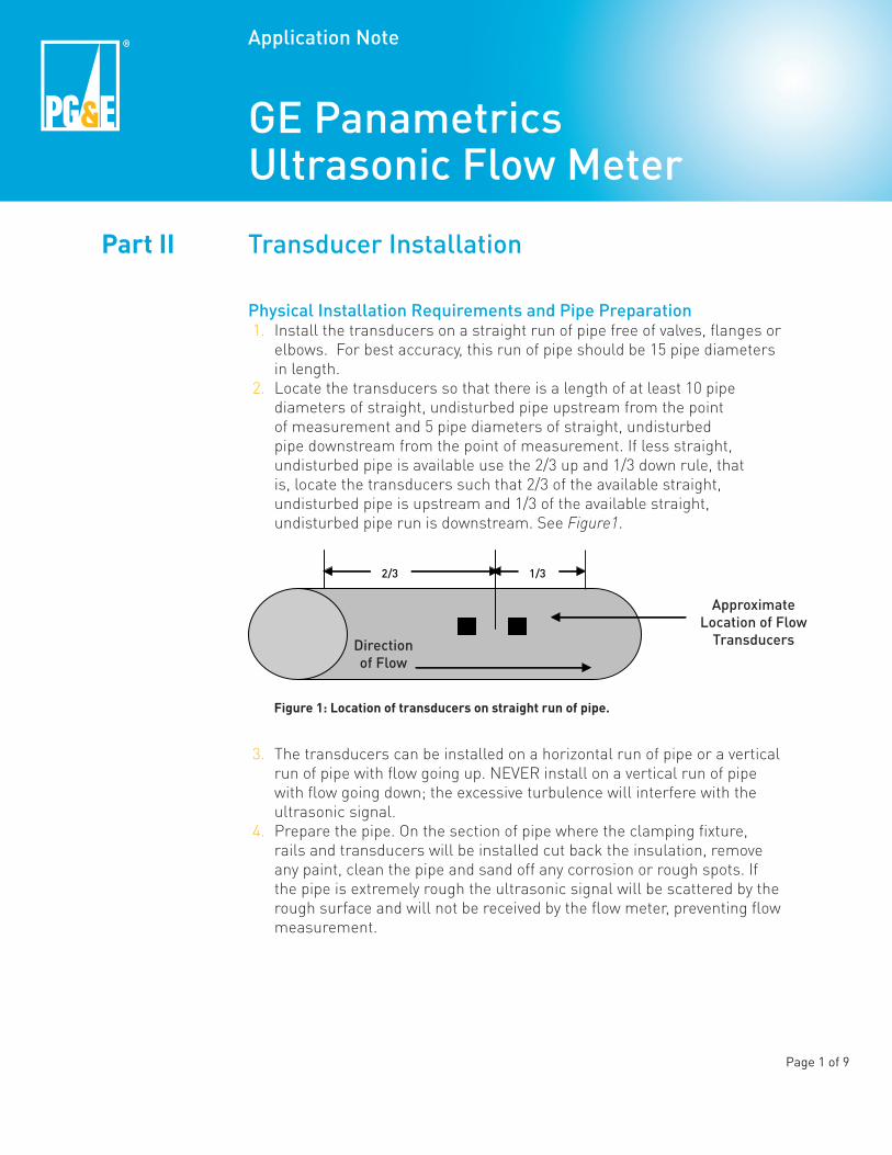
2. Locate the transducers so that there is a length of at least 10 pipe diameters of straight, undisturbed pipe upstream from the point of measurement and 5 pipe diameters of straight, undisturbed pipe downstream from the point of measurement. If less straight, undisturbed pipe is available use the 2/3 up and 1/3 down rule, that is, locate the transducers such that 2/3 of the available straight, undisturbed pipe is upstream and 1/3 of the available straight, undisturbed pipe run is downstream. See Figure1.
3. The transducers can be installed on a horizontal run of pipe or a vertical run of pipe with flow going up. NEVER install on a vertical run of pipe with flow going down; the excessive turbulence will interfere with the ultrasonic signal.
4. Prepare the pipe. On the section of pipe where the clamping fixture, rails and transducers will be installed cut back the insulation, remove any paint, clean the pipe and sand off any corrosion or rough spots. If the pipe is extremely rough the ultrasonic signal will be scattered by the rough surface and will not be received by the flow meter, preventing flow measurement.
Page 1 of 9
Application Note
GE Panametrics Ultrasonic Flow Meter
Transducer Installation
Figure 1: Location of transducers on straight run of pipe.
Part II

A
B
C
Installing #402 Transducers on Pipes Greater than 2” in DiameterFor pipes larger than 2” in diameter, #402 transducers are usually used. In this case, the two transducers are clamped to the pipe using a clamping mechanism as shown in Figure 2. The mechanism consists of two clamps connected by a pair of rails and secured to the pipe using chains and threaded hooks.
1. Before installation, make note of the Transducer Spacing value calculated by the PT878 on the Path tab, as described in Part I of this Application Note.
2. Slide the un-indexed rail into the slots on the two clamping fixtures located opposite the chain hooks, as shown in Figure 3A.
3. Slide the indexed rail into the slots on the two clamping fixtures located close to the chain hooks. Line the zero end of the indexed rail up exactly with the outside edge of one of the clamping fixtures, as shown in Figure 3B. Tighten the red screws on the marked and unmarked rails on this clamping fixture.
4. Slide the other clamping fixture along the indexed rail so that the inside edge of the fixture is lined up with the value on the rail that matches the Transducer Spacing value. See Figure 3C.
5. Tighten the remaining red screws on the clamping fixtures to secure it to the rails.
Figure 2: Transducers installed on pipe.
Page 2 of 9
Figure 3: Transducer clamp setup. A) Insert the un-indexed rail into the slots on the clamping fixtures located opposite the chain hooks. Then insert the indexed rail into the slots on the opposite side of the clamps.B) Line up the zero end of the indexed rail exactly with the outside edge of one of the clamping fixtures.C) Move the other clamping fixture along the indexed rail so that the inside edge of the fixture lines up with the value on the rail that matches the transducer spacing value. In this image the transducer spacing value is 3.55 inches.

A B C
D E
6. See Figure 4. For horizontal pipe runs, transducers should be placed within a cone 30° above and 30° below the horizontal axis of pipe to avoid signal interference from air and sediment.
7. Prepare the pipe in the areas that the transducers are to be installed as described in the Physical Installation Requirements and Pipe Preparation section above.
8. Install the clamping fixtures by wrapping each chain around the pipe and attaching it to the threaded hook. Tighten wing nuts to hold fixtures in place. Hand tighten only! See Figure 5A, 5B, and 5C.
9. Note that the transducers must be placed so that their co-axial cable connectors point away from each other, as shown in Figure 2 and Figure 5E.
10. Insert the transducers into the clamping fixtures to make sure they will fit between the set screws and the pipe. Adjust the set screws so that couplant will not be scraped off the transducers when they are inserted. Remove the transducers.
11. Spread a thick ridge of silicon grease across the center of the transducer along the line where it will contact the pipe. Reinsert the transducer into the appropriate clamping fixture. Use CPL-1 silicon grease for general applications below 150F and G-9030 silicon grease for higher temperature applications.
12. Replace transducer under set screw and tighten firmly with the large bolts located in the center of the clamping fixture. Hand tighten only! See Figure 5E.
Figure 4: Transducer placement on horizontal pipe run.
Page 3 of 9
Figure 5: Installing transducer clamps and transducers. A) Wrap each chain around the pipe. B) Attach chain to threaded hook. C) Tighten wing nut to hold clamping fixture in place. Hand tighten only! D) Insert transducers into clamping fixtures to make sure they will fit. Make adjustments as needed and remove transducers. E) Add a thick ridge of couplant to transducers. Reinsert transducers into the appropriate clamping fixture. Tighten set screws firmly with the set screws located in the center of each clamping fixture. Hand tighten only!
Table 1: Ultrasonic Couplants
Couplant Temp Range
CPL-1
G-9030
-40 - 150°F(-40 - 66°C)-40 - 445°F
(-40 - 230°C)

Direction of Flow
Upstream Transducer with RED Cable Sleeve.
Downstream Transducer with BLUE Cable Sleeve.
13. Repeat steps 11 and 12 for the second transducer.14. Attach the cables to the transducers. Make note of the color of the cable
sleeve that is attached to the upstream transducer and the downstream transducer. See Figure 6.
15. Proceed to Attaching Cables to Meter Section of this Application Note
Page 4 of 9
Figure 6: Identifying upstream and downstream cables. Note that the upstream transducer cable connector has a RED cable sleeve and the downstream transducer cable connector has a BLUE cable sleeve. On the meter-end of the cables, the connectors with the same color cable sleeves must be attached to corresponding upstream and downstream jacks on the TP878 meter.
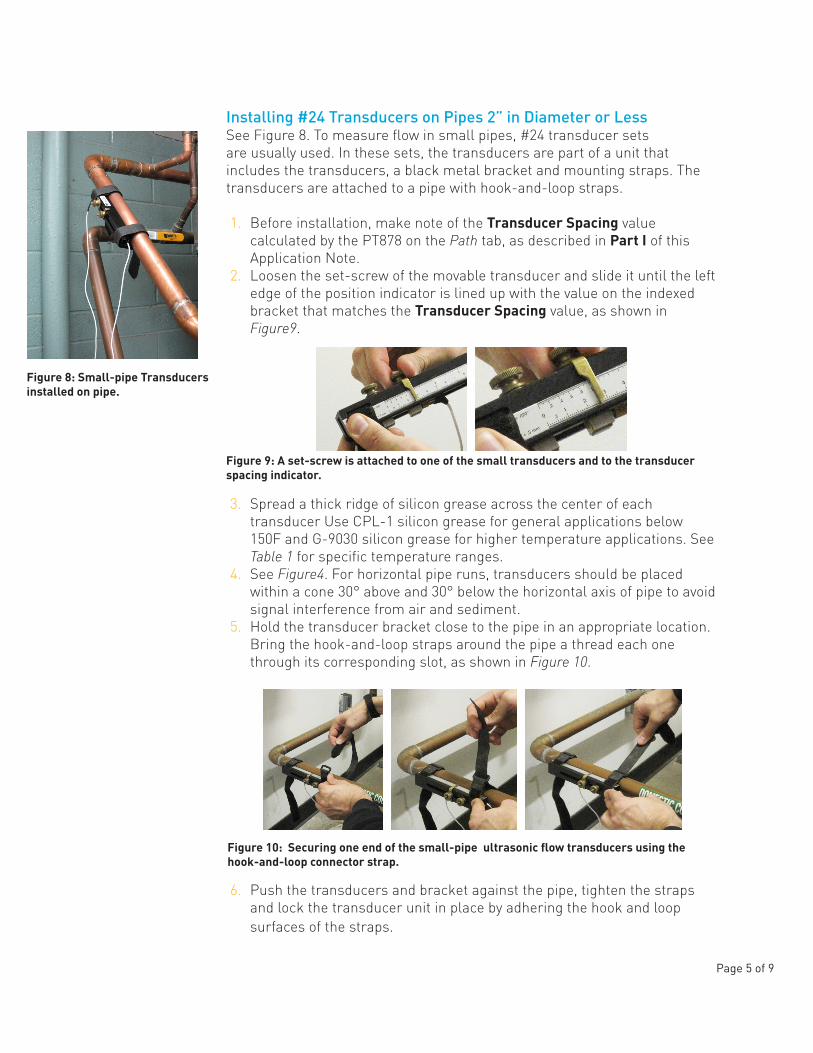
Installing #24 Transducers on Pipes 2” in Diameter or LessSee Figure 8. To measure flow in small pipes, #24 transducer sets are usually used. In these sets, the transducers are part of a unit that includes the transducers, a black metal bracket and mounting straps. The transducers are attached to a pipe with hook-and-loop straps.
1. Before installation, make note of the Transducer Spacing value calculated by the PT878 on the Path tab, as described in Part I of this Application Note.
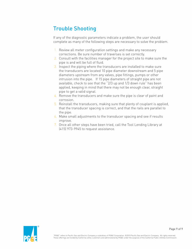
2. Loosen the set-screw of the movable transducer and slide it until the left edge of the position indicator is lined up with the value on the indexed bracket that matches the Transducer Spacing value, as shown in Figure9.
3. Spread a thick ridge of silicon grease across the center of each transducer Use CPL-1 silicon grease for general applications below 150F and G-9030 silicon grease for higher temperature applications. See Table 1 for specific temperature ranges.
4. See Figure4. For horizontal pipe runs, transducers should be placed within a cone 30° above and 30° below the horizontal axis of pipe to avoid signal interference from air and sediment.
5. Hold the transducer bracket close to the pipe in an appropriate location. Bring the hook-and-loop straps around the pipe a thread each one through its corresponding slot, as shown in Figure 10.
6. Push the transducers and bracket against the pipe, tighten the straps and lock the transducer unit in place by adhering the hook and loop surfaces of the straps.
Figure 8: Small-pipe Transducers installed on pipe.
Page 5 of 9
Figure 9: A set-screw is attached to one of the small transducers and to the transducer spacing indicator.
Figure 10: Securing one end of the small-pipe ultrasonic flow transducers using the hook-and-loop connector strap.

IR Port
Power Port
Input/Output Port
Downstream Transducer Port
Upstream Transducer Port
Installing #407 Transducers#407 transducers can be used with pipes from 1/2” to 6” in diameter. Their configuration is similar to that of #24 transducers, such that the instructions for installing #24 transducers can be used as a guide for the #407s.
Attaching Cables to Meter1. Attach the other ends of the transducer cables to the PT878 meter.
Make sure that the cable connected to the upstream transducer is inserted into the transducer cable port closer to the outside edge of the meter. Make sure the cable connected to the downstream transducer is inserted into the adjacent port. See Figure 7.
2. After the meter settles, a reasonable flow reading should be displayed on the meter. If there is a flashing Error Code Message (the letter E followed by a number flashing in the main screen’s System Tray) refer to the diagnostics section of this Application Note.
Page 6 of 9
Figure 7: PT878 ports. The upstream transducer port is closer to the outside edge of the meter. The downstream transducer port is adjacent to the upstream port. Use the cable sleeve colors to assure that the transducer cables connect the downstream and downstream ports to the corresponding transducers.

Removing Transducers
1. Remove the ultrasonic transducers before removing the clamps and rails to reduce the risk of dropping and damaging the transducer connectors.
2. Clean all couplant from transducers and other equipment before returning them to the case.
Diagnostics
PT878 provides error messages and diagnostics to alert the user to problems with meter configuration or transducer installation and to assist in trouble-shooting these problems. A set of key diagnostic parameters can be viewed on the PT878’s diagnostic test screen, or the meter can be configured to display selected diagnostic parameters on the main meter screen. In addition to this Application Note, Chapter 9 in the PT878 Operation & Installation Guide also provides information on interpreting diagnostics and trouble shooting.
1. To view the Diagnostic Tests screen (Figure 11), press F2 (Diagnostics), or press the Menu button and select Services and then Diagnostics.
Error Codes 2. If an error code other than 0x0000 appears (top left-hand corner of
Diagnostic Test screen), refer to Table 9-1 in Chapter 9 of the PT878 Operation & Installation Guide. For each error code, the table describes the problem indicated, the possible cause, and actions that may remedy the problem. Note that error codes will also appear in a box in the System Tray, located in the lower left-hand corner of the main meter screen.
Page 7 of 9
Figure 11: Diagnostics Tests screen.

Sound Speed3. If the sound speed measured by the PT878 differs significantly from the
expected sound speed for the fluid in question, it indicates a problem with meter configuration or transducer installation. For any fluid from the PT878 predefined fluid list, the PT878 displays an expected sound speed in Sound Speed field on the Fluid tab. If the measured sound speed is outside of the sound speed range indicated on the Fluid tab, and a Sound Speed (E2) Error will be displayed.
• For water, the PT878 will look up the expected sound speed based on the fluid temperature input by the user in the Temp field on the Fluid tab.
• For water-glycol mixtures, the unit defaults to 4915 f/s. If an E2 error results, try changing the fluid to Other and setting the sound speed to 5150 f/s.
4. If the user is unsure of the fluid sound speed, the PT878 can attempt to find the correct value by activating the Tracking Windows option of the Fluid tab.
5. If the measured sound speed is stable, but still results in an E2 error, on the Fluid tab, the fluid can be changed to Other and the measured sound speed entered as the expected sound speed. If the sound speed remains stable after this change, then this is the correct sound speed.
6. For sound speed data for a variety of fluids, see the Sound Speeds and Pipe Size Data Installation Reference provided with the PT878.
Signal Peak location (P#)7. Signal Peak (P#). The transducer signal peaks in a signal window that
is represented by arbitrary time units from 0 to 1000. The value of P# indicates where the peak occurs on this scale. For the most reliable signal, the peak should occur near the middle of this window or at a P# value of about 500. If the P# value is below 100 or above 900, no signal is recognized and indicates a problem with meter configuration or transducer installation.
Signal Strength (SS, or Signal)8. The table below indicates the quality of the ultrasonic signal based on its
signal strength value. The value of the upstream signal strength (SS up) should equal downstream value (SS do).
Other Parameters 9. For a complete list of diagnostic parameters, including descriptions and
guidance for interpreting their values, see Chapter 9, Table 9-2 in the Operation & Installation Guide.
Page 8 of 9
SS 40s
60-6850s
70s
Signal QualityPoor to Marginal
Very Good to ExcellentOkay to Good
Potential Signal Variation
“PG&E” refers to Pacific Gas and Electric Company, a subsidiary of PG&E Corporation. ©2010 Pacific Gas and Electric Company. All rights reserved. These offerings are funded by California utility customers and administered by PG&E under the auspices of the California Public Utilities Commission.
Trouble Shooting If any of the diagnostic parameters indicate a problem, the user should complete as many of the following steps are necessary to solve the problem.
1. Review all meter configuration settings and make any necessary corrections. Be sure number of traverses is set correctly.
2. Consult with the facilities manager for the project site to make sure the pipe is and will be full of fluid.
3. Inspect the piping where the transducers are installed to make sure the transducers are located 10 pipe diameter downstream and 5 pipe diameters upstream from any valves, pipe fittings, pumps or other intrusion into the pipe. If 15 pipe diameters of straight pipe are not available, check to see that the “2/3 up and 1/3 down rule” has been applied, keeping in mind that there may not be enough clear, straight pipe to get a valid signal.
4. Remove the transducers and make sure the pipe is clear of paint and corrosion.
5. Reinstall the transducers, making sure that plenty of couplant is applied, that the transducer spacing is correct, and that the rails are parallel to the pipe.
6. Make small adjustments to the transducer spacing and see if results improve.
7. Once all other steps have been tried, call the Tool Lending Library at (415) 973-9945 to request assistance.
Page 9 of 9