ge ethernet driver - opcturkey · environment. deviceproperties ......
TRANSCRIPT

GEEthernet Driver
© 2016 PTC Inc. All Rights Reserved.

GE Ethernet Driver
TableofContentsGE Ethernet Driver 1
Table of Contents 2
GE Ethernet Driver 5
Overview 5
Setup 6
Channel Properties 6
Channel Properties - General 6
Channel Properties - Ethernet Communications 7
Channel Properties - Write Optimizations 7
Channel Properties - Advanced 8
Device Properties 9
Device Properties - General 9
Device Properties - Scan Mode 11
Device Properties - Timing 12
Device Properties - Auto-Demotion 13
Device Properties - Tag Generation 13
Device Properties - Communications Settings 15
Device Properties - Variable Import Settings 16
Device Properties - PLC Settings 16
Device Properties - Redundancy 16
Automatic Tag Database Generation 17
Tag Hierarchy 17
Import File-to-Server NameConversions 18
Importing VersaPro Tags 19
VersaPro Import Preparation: VersaPro Steps 19
VersaPro Import Preparation: OPC Server Steps 21
Highlighting VersaPro Variables 21
VersaPro Array Tag Import 22
Importing Cimplicity Logic Developer Tags 23
Cimplicity Logic Developer Import Preparation: Logic Developer Steps 23
Cimplicity Logic Developer Import Preparation: OPC Server Steps 25
Highlighting Cimplicity Logic Developer Variables 25
Cimplicity Logic Developer Array Tag Import 25
Importing Proficy Logic Developer Tags 25
Proficy Logic Developer Import Preparation: Logic Developer Steps 26
Proficy Logic Developer Import Preparation: OPC Server Steps 28
www.kepware.com
2

GE Ethernet Driver
Highlighting Proficy Logic Developer Variables 28
Proficy Logic Developer Array Tag Import 29
Optimizing Communications 30
Data Types Description 32
Address Descriptions 33
PACSystems Addressing 33
Symbolic Variables 35
311 Addressing 38
313 Addressing 39
331 Addressing 40
341 Addressing 41
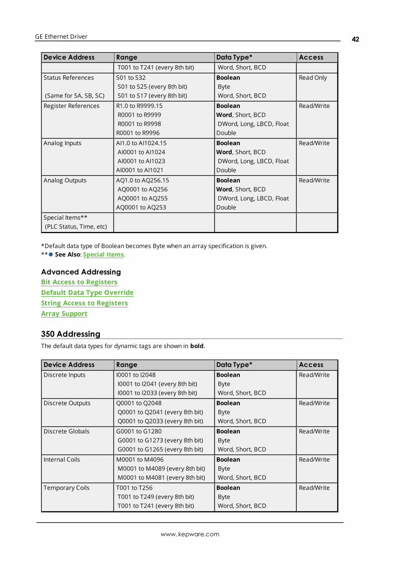
350 Addressing 42
360 Addressing 43
731 Addressing 44
732 Addressing 46
771 Addressing 47
772 Addressing 48
781 Addressing 50
782 Addressing 51
GEOPEN Addressing 53
Horner OCS Addressing 54
VersaMax Addressing 55
Advanced Addressing 56
Special Items 58
Error Descriptions 62
Address '<address>' is out of range for the specified device or register 63
Array size is out of range for address '<address>' 63
Array support is not available for the specified address: '<address>' 64
Data Type '<type>' is not valid for device address '<address>' 64
Device address '<address>' contains a syntax error 64
Device address '<address>' is not supported by model '<model name>' 64
Device address '<address>' is Read Only 64
Missing address 65
Attempting to reacquire symbolic variable mapping information for device '<device name>'.Cannot read or write symbolic variables until complete 65
Device '<device name>' not responding 65
Unable to write to '<address>' on device '<device name>' 66
www.kepware.com
3

GE Ethernet Driver
Bit access is invalid for the device data type '<native data type>' at address '<address>' in device'<device>' 66
Bit index '<bit index>' is not valid for the device data type '<native data type>' at address'<address>' in device '<device>' 66
Device '<device name>' returned error code <error num> reading n byte(s) starting at <address> 66
The address length of the symbolic variable addressed by '<tag name>' on device '<device>' isbigger than the configured block size for this device. Deactivating tag 67
The array size of address '<address>' on device '<device name>' must be the same as symbolicvariable's array size of [rows][cols] 67
The data type of the symbolic variable addressed by '<address>' on device '<device name>' is notcompatible with tag 67
The symbolic discrete array size of '<size in bytes>' bytes at address '<address>' on device'<device>' exceeds the configured '<block size>' maximum request bytes. 68
The symbolic variable name in tag address '<address>' does not exist in current configuration ofdevice '<device name>'. 68
Winsock initialization failed (OS Error = n) 69
Winsock V1.1 or higher must be installed to use the GE Ethernet device driver 69
Database Error: Array tags [orig. tag name] [dimensions] exceed 256 characters. Tags renamedto [new tag name] [dimensions] 69
Database Error: Data type '<type>' arrays are currently not supported. Tag '<array tag name>'not created 69
Database Error: Data type '<type>' for tag '<tag name>' is currently not supported. Tag notcreated. 70
Database Error: Data type '<type>' for tag '<tag name>' not found in import file. Setting to default.70
Database Error: Logic Developer Variable Arrays are currently not supported. Array Tag(s)'<array tag name>' not created 70
Database Error: No Reference Address found for tag '<tag name>' in import file. Tag not created 71
Database Error: Only variables with Data Source '<data source name>' are imported. DataSource '<data source name>' is not supported. Tag '<tag name>' not created 71
Database Error: Tag '<orig. tag name>' exceeds 256 characters. Tag renamed to '<new tagname>' 71
Unable to generate a tag database for device <device name>. Reason: Import file is invalid orcorrupt 71
Unable to generate a tag database for device <device name>. Reason: Lowmemory resources 72
Index 73
www.kepware.com
4

GE Ethernet Driver
GE Ethernet DriverHelp version 1.064
CONTENTS
OverviewWhat is the GE Ethernet Driver?
Device SetupHow do I configure a device for use with this driver?
Automatic Tag Database GenerationHow can I easily configure tags for the GE Ethernet Driver?
Optimizing Your GE Ethernet CommunicationsHow do I get the best performance from the GE Ethernet Driver?
Data Types DescriptionWhat data types does this driver support?
Address DescriptionsHow do I address a data location on a GE device?
Error DescriptionsWhat error messages does the driver produce?
OverviewThe GE Ethernet Driver provides a reliable way to connect GE Ethernet controllers to OPC Clientapplications; including HMI, SCADA, Historian, MES, ERP and countless custom applications. It is intended foruse with GE Programmable Logic Controllers that may be accessed via an Ethernet module.
www.kepware.com
5

GE Ethernet Driver
Setup
Supported DevicesSeries 90-30 311/313, 331/341, 350, 360Series 90-70 731/732, 771/772, 781/782GE OPEN (Wide Range Model Support)Horner OCS (Horner's Operator Control Stations)PACSystems RX3i and RX7iVersaMax Family
Communication ProtocolEthernet, using Winsock V1.1 or higher.
Channel PropertiesDevice Properties
Channel PropertiesThis server supports the use of simultaneous multiple communications drivers. Each protocol or driver usedin a server project is called a channel. A server project may consist of many channels with the samecommunications driver or with unique communications drivers. A channel acts as the basic building block ofan OPC link.
The properties associated with a channel are broken in to logical groupings. While some groups are specificto a given driver or protocol, the following are the common groups:
GeneralEthernet or Serial CommunicationsWrite OptimizationAdvanced
Channel Properties - GeneralThis server supports the use of simultaneous multiple communications drivers. Each protocol or driver usedin a server project is called a channel. A server project may consist of many channels with the samecommunications driver or with unique communications drivers. A channel acts as the basic building block ofan OPC link. This group is used to specify general channel properties, such as the identification attributesand operating mode.
Identification
www.kepware.com
6

GE Ethernet Driver
Name: User-defined identity of this channel. In each server project, each channel name must be unique.Although names can be up to 256 characters, some client applications have a limited display window whenbrowsing the OPC server's tag space. The channel name is part of the OPC browser information.Ã For information on reserved characters, refer to "How To... Properly Name a Channel, Device, Tag, and TagGroup" in the server help.
Description: User-defined information about this channel.Ã Many of these properties, including Description, have an associated system tag.
Driver: Selected protocol / driver for this channel. This property specifies the device driver that was selectedduring channel creation. It is a disabled setting in the channel properties.
à Note: With the server's online full-time operation, these properties can be changed at any time. Thisincludes changing the channel name to prevent clients from registering data with the server. If a client hasalready acquired an item from the server before the channel name is changed, the items are unaffected. If,after the channel name has been changed, the client application releases the item and attempts to re-acquire using the old channel name, the item is not accepted. With this in mind, changes to the propertiesshould not be made once a large client application has been developed. Utilize the User Manager to preventoperators from changing properties and restrict access rights to server features.
Diagnostics
Diagnostics Capture: When enabled, this optionmakes the channel's diagnostic information available toOPC applications. Because the server's diagnostic features require a minimal amount of overheadprocessing, it is recommended that they be utilized when needed and disabled when not. The default isdisabled.Ã For more information, refer to "Communication Diagnostics" in the server help.Ã Note: Not all drivers support diagnostics. To determine whether diagnostics are available for a particulardriver, open the driver information and locate the "Supports device level diagnostics" statement.
Channel Properties - Ethernet CommunicationsEthernet Communication can be used to communicate with devices.
Ethernet Settings
Network Adapter: Specify the network adapter to bind. When Default is selected, the operating systemselects the default adapter.
Channel Properties - Write OptimizationsAs with any OPC server, writing data to the device may be the application's most important aspect. Theserver intends to ensure that the data written from the client application gets to the device on time. Giventhis goal, the server provides optimization properties that can be used to meet specific needs or improveapplication responsiveness.
www.kepware.com
7
GE Ethernet Driver
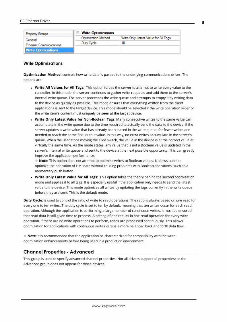
Write Optimizations
Optimization Method: controls how write data is passed to the underlying communications driver. Theoptions are:
l Write All Values for All Tags: This option forces the server to attempt to write every value to thecontroller. In this mode, the server continues to gather write requests and add them to the server'sinternal write queue. The server processes the write queue and attempts to empty it by writing datato the device as quickly as possible. This mode ensures that everything written from the clientapplications is sent to the target device. This mode should be selected if the write operation order orthe write item's content must uniquely be seen at the target device.
l Write Only Latest Value for Non-Boolean Tags: Many consecutive writes to the same value canaccumulate in the write queue due to the time required to actually send the data to the device. If theserver updates a write value that has already been placed in the write queue, far fewer writes areneeded to reach the same final output value. In this way, no extra writes accumulate in the server'squeue. When the user stops moving the slide switch, the value in the device is at the correct value atvirtually the same time. As the mode states, any value that is not a Boolean value is updated in theserver's internal write queue and sent to the device at the next possible opportunity. This can greatlyimprove the application performance.Ã Note: This option does not attempt to optimize writes to Boolean values. It allows users tooptimize the operation of HMI data without causing problems with Boolean operations, such as amomentary push button.
l Write Only Latest Value for All Tags: This option takes the theory behind the second optimizationmode and applies it to all tags. It is especially useful if the application only needs to send the latestvalue to the device. This mode optimizes all writes by updating the tags currently in the write queuebefore they are sent. This is the default mode.
Duty Cycle: is used to control the ratio of write to read operations. The ratio is always based on one read forevery one to ten writes. The duty cycle is set to ten by default, meaning that ten writes occur for each readoperation. Although the application is performing a large number of continuous writes, it must be ensuredthat read data is still given time to process. A setting of one results in one read operation for every writeoperation. If there are no write operations to perform, reads are processed continuously. This allowsoptimization for applications with continuous writes versus a more balanced back and forth data flow.
à Note: It is recommended that the application be characterized for compatibility with the writeoptimization enhancements before being used in a production environment.
Channel Properties - AdvancedThis group is used to specify advanced channel properties. Not all drivers support all properties; so theAdvanced group does not appear for those devices.
www.kepware.com
8

GE Ethernet Driver
Non-Normalized Float Handling: Non-normalized float handling allows users to specify how a driverhandles non-normalized IEEE-754 floating point data. A non-normalized value is defined as Infinity, Not-a-Number (NaN), or as a Denormalized Number. The default is Replace with Zero. Drivers that have nativefloat handling may default to Unmodified. Descriptions of the options are as follows:
l Replace with Zero: This option allows a driver to replace non-normalized IEEE-754 floating pointvalues with zero before being transferred to clients.
l Unmodified: This option allows a driver to transfer IEEE-754 denormalized, normalized, non-number, and infinity values to clients without any conversion or changes.
à Note: This property is disabled if the driver does not support floating point values or if it only supports theoption that is displayed. According to the channel's float normalization setting, only real-time driver tags(such as values and arrays) are subject to float normalization. For example, EFM data is not affected by thissetting.lin
à For more information on the floating point values, refer to "How To ... Work with Non-Normalized FloatingPoint Values" in the server help.
Device PropertiesDevice properties are organized into the following groups. Click on a link below for details about theproperties in that group.
IdentificationOperating ModeScan ModeCommunication TimeoutsAuto-DemotionRedundancy
Device Properties - GeneralA device represents a single target on a communications channel. If the driver supports multiple controllers,users must enter a device ID for each controller.
www.kepware.com
9

GE Ethernet Driver
Identification
Name: This property specifies the name of the device. It is a logical user-defined name that can be up to256 characters long, andmay be used onmultiple channels.
à Note: Although descriptive names are generally a good idea, some OPC client applications may have alimited display window when browsing the OPC server's tag space. The device name and channel namebecome part of the browse tree information as well. Within an OPC client, the combination of channel nameand device name would appear as "ChannelName.DeviceName".à For more information, refer to "How To... Properly Name a Channel, Device, Tag, and Tag Group" in serverhelp.
Description: User-defined information about this device.Ã Many of these properties, including Description, have an associated system tag.
Channel Assignment: User-defined name of the channel to which this device currently belongs.
Driver: Selected protocol driver for this device.
Model: This property specifies the specific type of device that is associated with this ID. The contents of thedrop-downmenu depends on the type of communications driver being used. Models that are not supportedby a driver are disabled. If the communications driver supports multiple device models, the model selectioncan only be changed when there are no client applications connected to the device.
à Note: If the communication driver supports multiple models, users should try to match the modelselection to the physical device. If the device is not represented in the drop-downmenu, select a model thatconforms closest to the target device. Some drivers support a model selection called "Open," which allowsusers to communicate without knowing the specific details of the target device. For more information, referto the driver help documentation.
ID: This property specifies the device's driver-specific station or node. The type of ID entered depends onthe communications driver being used. For many communication drivers, the ID is a numeric value. Driversthat support a Numeric ID provide users with the option to enter a numeric value whose format can bechanged to suit the needs of the application or the characteristics of the selected communications driver.The ID format can be Decimal, Octal, and Hexadecimal.
à Note: If the driver is Ethernet-based or supports an unconventional station or node name, the device'sTCP/IP address may be used as the device ID. TCP/IP addresses consist of four values that are separated byperiods, with each value in the range of 0 to 255. Some device IDs are string based. There may be additional
www.kepware.com
10

GE Ethernet Driver
properties to configure within the ID field, depending on the driver. For more information, refer to thedriver's help documentation.
Operating Mode
Data Collection: This property controls the device's active state. Although device communications areenabled by default, this property can be used to disable a physical device. Communications are notattempted when a device is disabled. From a client standpoint, the data is marked as invalid and writeoperations are not accepted. This property can be changed at any time through this property or the devicesystem tags.
Simulated: This option places the device into Simulation Mode. In this mode, the driver does not attempt tocommunicate with the physical device, but the server continues to return valid OPC data. Simulated stopsphysical communications with the device, but allows OPC data to be returned to the OPC client as valid data.While in Simulation Mode, the server treats all device data as reflective: whatever is written to the simulateddevice is read back and each OPC item is treated individually. The item's memory map is based on the groupUpdate Rate. The data is not saved if the server removes the item (such as when the server is reinitialized).The default is No.
à Notes:
1. This System tag (_Simulated) is read only and cannot be written to for runtime protection. The Systemtag allows this property to be monitored from the client.
2. In Simulationmode, the item's memory map is based on client update rate(s) (Group Update Rate forOPC clients or Scan Rate for native and DDE interfaces). This means that two clients that referencethe same item with different update rates return different data.
à Simulation Mode is for test and simulation purposes only. It should never be used in a productionenvironment.
Device Properties - Scan ModeThe ScanMode specifies the subscribed-client requested scan rate for tags that require devicecommunications. Synchronous and asynchronous device reads and writes are processed as soon aspossible; unaffected by the ScanMode properties.
Scan Mode: specifies how tags in the device are scanned for updates sent to subscribed clients.Descriptions of the options are:
l Respect Client-Specified Scan Rate: This mode uses the scan rate requested by the client.l Request Data No Faster than Scan Rate: This mode specifies the maximum scan rate to be used.
The valid range is 10 to 99999990 milliseconds. The default is 1000 milliseconds.Ã Note: When the server has an active client and items for the device and the scan rate value isincreased, the changes take effect immediately. When the scan rate value is decreased, the changesdo not take effect until all client applications have been disconnected.
l Request All Data at Scan Rate: This mode forces tags to be scanned at the specified rate forsubscribed clients. The valid range is 10 to 99999990 milliseconds. The default is 1000 milliseconds.
www.kepware.com
11
GE Ethernet Driver
l Do Not Scan, Demand Poll Only: This mode does not periodically poll tags that belong to thedevice nor perform a read to get an item's initial value once it becomes active. It is the client'sresponsibility to poll for updates, either by writing to the _DemandPoll tag or by issuing explicit devicereads for individual items. For more information, refer to "Device Demand Poll" in server help.
l Respect Tag-Specified Scan Rate: This mode forces static tags to be scanned at the rate specifiedin their static configuration tag properties. Dynamic tags are scanned at the client-specified scanrate.
Initial Updates from Cache: When enabled, this option allows the server to provide the first updates fornewly activated tag references from stored (cached) data. Cache updates can only be provided when thenew item reference shares the same address, scan rate, data type, client access, and scaling properties. Adevice read is used for the initial update for the first client reference only. The default is disabled; any time aclient activates a tag reference the server attempts to read the initial value from the device.
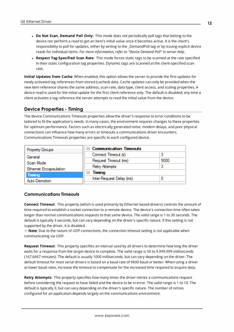
Device Properties - TimingThe device Communications Timeouts properties allow the driver's response to error conditions to betailored to fit the application's needs. In many cases, the environment requires changes to these propertiesfor optimum performance. Factors such as electrically generated noise, modem delays, and poor physicalconnections can influence howmany errors or timeouts a communications driver encounters.Communications Timeouts properties are specific to each configured device.
Communications Timeouts
Connect Timeout: This property (which is used primarily by Ethernet based drivers) controls the amount oftime required to establish a socket connection to a remote device. The device's connection time often takeslonger than normal communications requests to that same device. The valid range is 1 to 30 seconds. Thedefault is typically 3 seconds, but can vary depending on the driver's specific nature. If this setting is notsupported by the driver, it is disabled.Ã Note: Due to the nature of UDP connections, the connection timeout setting is not applicable whencommunicating via UDP.
Request Timeout: This property specifies an interval used by all drivers to determine how long the driverwaits for a response from the target device to complete. The valid range is 50 to 9,999,999 milliseconds(167.6667 minutes). The default is usually 1000 milliseconds, but can vary depending on the driver. Thedefault timeout for most serial drivers is based on a baud rate of 9600 baud or better. When using a driverat lower baud rates, increase the timeout to compensate for the increased time required to acquire data.
Retry Attempts: This property specifies howmany times the driver retries a communications requestbefore considering the request to have failed and the device to be in error. The valid range is 1 to 10. Thedefault is typically 3, but can vary depending on the driver's specific nature. The number of retriesconfigured for an application depends largely on the communications environment.
www.kepware.com
12

GE Ethernet Driver
Timing
Inter-Request Delay: This property specifies how long the driver waits before sending the next request tothe target device. It overrides the normal polling frequency of tags associated with the device, as well asone-time reads and writes. This delay can be useful when dealing with devices with slow turnaround timesand in cases where network load is a concern. Configuring a delay for a device affects communications withall other devices on the channel. It is recommended that users separate any device that requires an inter-request delay to a separate channel if possible. Other communications properties (such as communicationserialization) can extend this delay. The valid range is 0 to 300,000 milliseconds; however, some drivers maylimit the maximum value due to a function of their particular design. The default is 0, which indicates nodelay between requests with the target device.Ã Note: Not all drivers support Inter-Request Delay. This setting does not appear if it is not supported by thedriver.
Device Properties - Auto-DemotionThe Auto-Demotion properties can temporarily place a device off-scan in the event that a device is notresponding. By placing a non-responsive device offline for a specific time period, the driver can continue tooptimize its communications with other devices on the same channel. After the time period has beenreached, the driver re-attempts to communicate with the non-responsive device. If the device is responsive,the device is placed on-scan; otherwise, it restarts its off-scan time period.
Demote on Failure: When enabled, the device is automatically taken off-scan until it is responding again.Ã Tip: Determine when a device is off-scan by monitoring its demoted state using the _AutoDemotedsystem tag.
Timeouts to Demote: Specify howmany successive cycles of request timeouts and retries occur before thedevice is placed off-scan. The valid range is 1 to 30 successive failures. The default is 3.
Demotion Period: Indicate how long the device should be placed off-scan when the timeouts value isreached. During this period, no read requests are sent to the device and all data associated with the readrequests are set to bad quality. When this period expires, the driver places the device on-scan and allows foranother attempt at communications. The valid range is 100 to 3600000 milliseconds. The default is 10000milliseconds.
Discard Requests when Demoted: Select whether or not write requests should be attempted during theoff-scan period. Disable to always send write requests regardless of the demotion period. Enable to discardwrites; the server automatically fails any write request received from a client and does not post a messageto the Event Log.
Device Properties - Tag GenerationThe automatic tag database generation features make setting up the an application a plug-and-playoperation. Select communications drivers can be configured to automatically build a list of tags that
www.kepware.com
13

GE Ethernet Driver
correspond to device-specific data. These automatically generated tags (which depend on the nature of thesupporting driver) can be browsed from the clients.
If the target device supports its own local tag database, the driver reads the device's tag information anduses the data to generate tags within the server. If the device does not natively support named tags, thedriver creates a list of tags based on driver-specific information. An example of these two conditions is asfollows:
1. If a data acquisition system supports its own local tag database, the communications driver uses thetag names found in the device to build the server's tags.
2. If an Ethernet I/O system supports detection of its own available I/Omodule types, thecommunications driver automatically generates tags in the server that are based on the types of I/Omodules plugged into the Ethernet I/O rack.
à Note: Automatic tag database generation's mode of operation is completely configurable. For moreinformation, refer to the property descriptions below.
On Device StartupThis property specifies when OPC tags are automatically generated. Descriptions of the options are asfollows:
l Do Not Generate on Startup: This option prevents the driver from adding any OPC tags to the tagspace of the server. This is the default setting.
l Always Generate on Startup: This option causes the driver to evaluate the device for taginformation. It also adds tags to the tag space of the server every time the server is launched.
l Generate on First Startup: This option causes the driver to evaluate the target device for taginformation the first time the project is run. It also adds any OPC tags to the server tag space asneeded.
à Note: When the option to automatically generate OPC tags is selected, any tags that are added to theserver's tag space must be saved with the project. Users can configure the project to automatically savefrom the Tools | Optionsmenu.
On Duplicate TagWhen automatic tag database generation is enabled, the server needs to know what to do with the tags thatit may have previously added or with tags that have been added or modified after the communicationsdriver since their original creation. This setting controls how the server handles OPC tags that wereautomatically generated and currently exist in the project. It also prevents automatically generated tagsfrom accumulating in the server.
For example, if a user changes the I/Omodules in the rack with the server configured to Always Generateon Startup, new tags would be added to the server every time the communications driver detected a newI/Omodule. If the old tags were not removed, many unused tags could accumulate in the server's tag space.The options are:
www.kepware.com
14

GE Ethernet Driver
l Delete on Create: This option deletes any tags that were previously added to the tag space beforeany new tags are added. This is the default setting.
l Overwrite as Necessary: This option instructs the server to only remove the tags that thecommunications driver is replacing with new tags. Any tags that are not being overwritten remain inthe server's tag space.
l Do not Overwrite: This option prevents the server from removing any tags that were previouslygenerated or already existed in the server. The communications driver can only add tags that arecompletely new.
l Do not Overwrite, Log Error: This option has the same effect as the prior option, and also posts anerror message to the server's Event Log when a tag overwrite would have occurred.
à Note: Removing OPC tags affects tags that have been automatically generated by thecommunications driver as well as any tags that have been added using names that match generatedtags. Users should avoid adding tags to the server using names that may match tags that areautomatically generated by the driver.
Parent Group: This property keeps automatically generated tags frommixing with tags that have beenenteredmanually by specifying a group to be used for automatically generated tags. The name of the groupcan be up to 256 characters. This parent group provides a root branch to which all automatically generatedtags are added.
Allow Automatically Generated Subgroups: This property controls whether the server automaticallycreates subgroups for the automatically generated tags. This is the default setting. If disabled, the servergenerates the device's tags in a flat list without any grouping. In the server project, the resulting tags arenamed with the address value. For example, the tag names are not retained during the generation process.
à Note: If, as the server is generating tags, a tag is assigned the same name as an existing tag, the systemautomatically increments to the next highest number so that the tag name is not duplicated. For example, ifthe generation process creates a tag named "AI22" that already exists, it creates the tag as "AI23" instead.
Create: Initiates the creation of automatically generated OPC tags. If the device's configuration has beenmodified, Create tags forces the driver to reevaluate the device for possible tag changes. Its ability to beaccessed from the System tags allows a client application to initiate tag database creation.
à Note: Create tags is disabled if the Configuration edits a project offline.
Device Properties - Communications SettingsDefine the device's port number and the maximum number of bytes of data that can be received in a singlerequest.
TCP/IP Port: Specify the TCP/IP port number that the remote device is configured to use. The default settingis 18245.
www.kepware.com
15

GE Ethernet Driver
Maximum Bytes Per Request: Specify the number of bytes that may be requested from a device at onetime. To refine this driver's performance, configure the request size to one of the following settings: 32, 64,128, 256, 512, 1024, or 2048 bytes. The default value is 2048 bytes.
Device Properties - Variable Import Settings
Variable Import File: This property specifies the exact location of the variable import file (.snf or .csv fileextension) or Logic Developer variable import file (.txt or other file extension) from which variables will beimported. It is this file that will be used when Automatic Tag Database Generation is instructed to create thetag database. All tags will be imported and expanded according to their respective data types.
Display Descriptions: When enabled, this option imports tag descriptions. If necessary, a description isgiven to tags with long names that state the original tag name. Default setting is Enable.
Use Alias Data Type If Possible: Enable to use the data type assigned to an alias tag in the import file. Ifthe alias data type is incompatible with the source tag data type, the source tag data type is used instead.Default setting is Disable.
à See Also: Automatic Tag Database Generation
Device Properties - PLC Settings
CPU Slot Location: Specify the physical location of the device on the rack. Depending on the model, the CPUmay be fixed and therefore unmodifiable. For CPUs that take up two slots, the leftmost slot covered is theCPU slot. The valid range is 0 to 15. The default setting is slot 1.
Device Properties - Redundancy
Redundancy is available with the Media-Level Redundancy Plug-in.
à Consult the website, a sales representative, or the user manual for more information.
www.kepware.com
16

GE Ethernet Driver
Automatic Tag Database GenerationThe GE Ethernet Device Driver generates its tags offline based on variables imported from a text file. It isoffline in that a connection to the device is not required to generate tags. The text file (variables to import)can originate from one of the following applications:
1. Proficy Machine Edition - Logic Developer
2. Cimplicity Machine Edition - Logic Developer
3. VersaPro
There are two parts to Automatic Tag Database Generation: creating a variable import file from theapplication in use and generating tags based on the variable import file from the OPC server.Ã Resources:For information on creating variable import files, refer to Importing VersaPro Tags, Importing Proficy LogicDeveloper Tags or Importing Cimplicity Logic Developer Tags.For information on generating tags based on the import file, refer to Variable Import Settings and TagGeneration.
Generating Tag Database While Preserving Previously Generated Tag DatabasesUnder certain circumstances, multiple imports into the server are required to import all tags of interest. Thisis the case with importing VersaPro System variables and non-System variables into the same OPC serverproject. In the Tag Generation property group under Device Properties, click on the property On DuplicateTag. After the first OPC server import/database creation completes, set the action to Do not overwrite orDo not overwrite, log error for future imports. This allows tags to be imported without deleting oroverwriting tags that were previously imported.
Tag HierarchyThe tags created through Automatic Tag Generation follow a specific hierarchy. The root level groups (orsubgroup levels of the group specified in the "Add generated tags to the following group" property) aredetermined by the variable addresses referenced (such as R, G, M, and so forth). For example, everyvariable that is of address type "R" will be placed in a root level group called "R". Each array tag is providedin its own subgroup of the parent group. The name of the array subgroup provides a description of the array.For example, an array "R10[6]" defined in the import file would have a subgroup name "R10_x". X signifiesthat dimension 1 exists.
Tags in "R10_x" GroupTag Name Tag Address CommentR10_x R10[6] Full array
R10_10 R10 Array element 1
R10_11 R11 Array element 2
R10_12 R12 Array element 3
R10_13 R13 Array element 4
R10_14 R14 Array element 5
R10_15 R15 Array element 6
Symbolic Variable ArraysSymbolic variable tags (in PACSystems only) are placed in a group called Symbolic. Symbolic variable arraysare not automatically broken out into individual element tags, and will not be placed in a separate group. Asingle array tag will be generated for each symbolic variable array in the Symbolic group. For example, if a
www.kepware.com
17
GE Ethernet Driver
2x3 array of symbolic variables named "MySymbolicArray" is defined in the import file, then a single tag withname "MySymbolicArray" and address "!MySymbolicArray"[2][3] would be generated in the Symbolic group.
Although symbolic variable arrays are not automatically broken out into individual array element tags, anarray element tag will be placed in the Symbolic group if an individual array element symbolic variable islisted in the import file. For example, an import file that contains an entry for array element (0,1) of the"MySymbolicArray" would appear as "MySymbolicArray[0,1]". A tag with address "!MySymbolicArray{0}{1}"would be generated in the Symbolic group.
See Also: Symbolic Variables
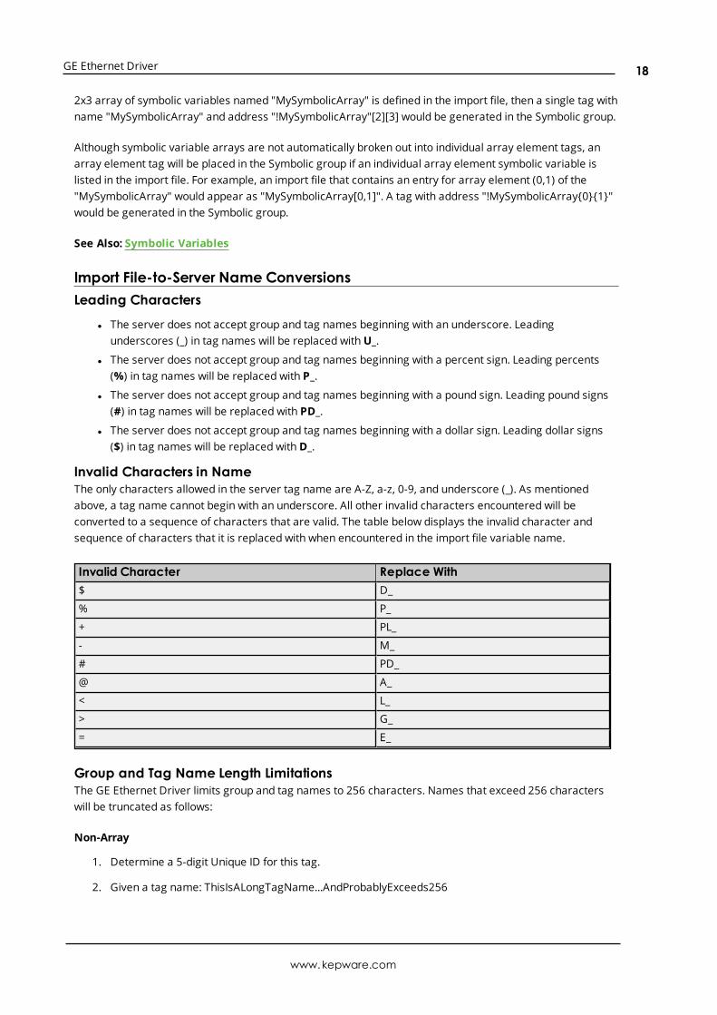
Import File-to-Server Name ConversionsLeading Characters
l The server does not accept group and tag names beginning with an underscore. Leadingunderscores (_) in tag names will be replaced withU_.
l The server does not accept group and tag names beginning with a percent sign. Leading percents(%) in tag names will be replaced with P_.
l The server does not accept group and tag names beginning with a pound sign. Leading pound signs(#) in tag names will be replaced with PD_.
l The server does not accept group and tag names beginning with a dollar sign. Leading dollar signs($) in tag names will be replaced withD_.
Invalid Characters in NameThe only characters allowed in the server tag name are A-Z, a-z, 0-9, and underscore (_). As mentionedabove, a tag name cannot begin with an underscore. All other invalid characters encountered will beconverted to a sequence of characters that are valid. The table below displays the invalid character andsequence of characters that it is replaced with when encountered in the import file variable name.
Invalid Character Replace With$ D_
% P_
+ PL_
- M_
# PD_
@ A_
< L_
> G_
= E_
Group and Tag Name Length LimitationsThe GE Ethernet Driver limits group and tag names to 256 characters. Names that exceed 256 characterswill be truncated as follows:
Non-Array
1. Determine a 5-digit Unique ID for this tag.
2. Given a tag name: ThisIsALongTagName...AndProbablyExceeds256
www.kepware.com
18
GE Ethernet Driver
3. Truncate tag at 256: ThisIsALongTagName...AndProbablyEx
4. Room is made for the Unique ID: ThisIsALongTagName...AndProba#####
5. Insert this ID: ThisIsALongTagName...AndProba00000
Array
1. Determine a 5-digit Unique ID for this array.
2. Given an array tag name: ThisIsALongTagName...AndProbablyExceeds256_23
3. Truncate tag at 256 while holding on to the element values: ThisIsALongTagNameAndPr_23
4. Room is made for the Unique ID: ThisIsALongTagName...#####_23
5. Insert this ID: ThisIsALongTagName...00001_23
Importing VersaPro TagsThis driver uses Shared Name Files (SNF) that are generated from VersaPro in order to generate the tagdatabase. Certain aspects of the Automatic Tag Database Generation process depend on the applicationfrom which variables are imported. For more information on a specific aspect of VersaPro tag import, selecta link from the list below.
VersaPro Import Preparation: VersaPro StepsVersaPro Import Preparation: OPC Server StepsHighlighting VersaPro VariablesVersaPro Array Tag Import
à Note: To import tags using a different application, refer to Automatic Tag Database Generation toverify that the application is supported.
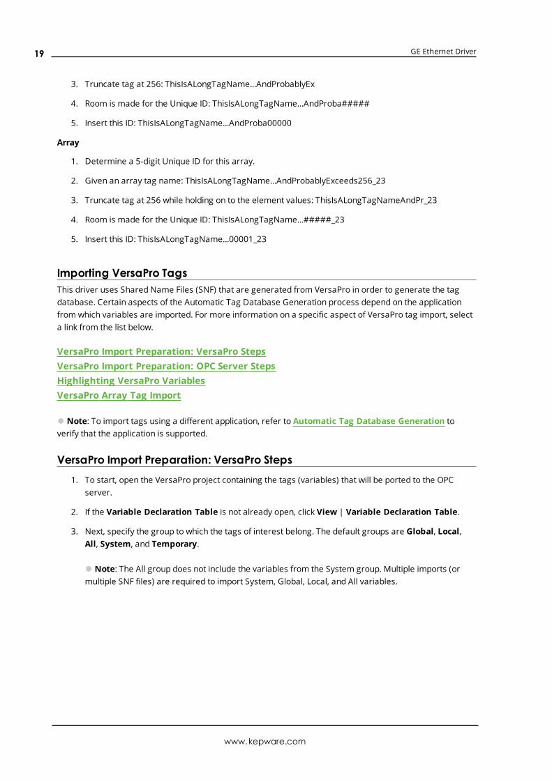
VersaPro Import Preparation: VersaPro Steps1. To start, open the VersaPro project containing the tags (variables) that will be ported to the OPC
server.
2. If the Variable Declaration Table is not already open, click View | Variable Declaration Table.
3. Next, specify the group to which the tags of interest belong. The default groups are Global, Local,All, System, and Temporary.
à Note: The All group does not include the variables from the System group. Multiple imports (ormultiple SNF files) are required to import System, Global, Local, and All variables.
www.kepware.com
19

GE Ethernet Driver
4. Next, click on the group's tab to bring its variables to the front. Then, highlight the tags of interest andclick Tools | Export Variables.
www.kepware.com
20

GE Ethernet Driver
5. When prompted, select Shared Name File (*.snf) and specify a name.
à Note: VersaPro will export the project's contents into this SNF file.
See Also: Highlighting VersaPro Variables
VersaPro Import Preparation: OPC Server Steps1. To start, right-click on the device for which tags will be generated and select Device Properties.
Then, open the Variable Import Settings property group.
2. In Variable Import File, enter or browse for the location of the VersaPro *.snf file newly created.Then, click Apply.
3. Next, select the Tag Generation property group. Then, click Create Tags.
4. The OPC server will state in the Event Log that it is attempting to perform a tag import. Whenfinished, it will state that the tag import has completed. All variables exported out of VersaPro willappear in the OPC server in the layout discussed in Tag Hierarchy.
5. Once finished, clickOK.
See Also: Variable Import Settings
Highlighting VersaPro VariablesVariables can be highlighted in VersaPro in the following ways:
www.kepware.com
21

GE Ethernet Driver
l Single Variable Selecting: To do so, left-click on a variable of interest while pressing CTRL.
l Selecting a Range of Variables: To do so, left-click on the first variable in the range of interest.Then, press SHIFT while left-clicking on the last variable in the range. All variables in the range will behighlighted.
l Selecting All Variables: To do so, left-click on a variable within the group of interest in the VariableDeclaration Table. The variable chosen is irrelevant. Then, click Edit | Select All. All variables will behighlighted with that group.
VersaPro Array Tag ImportVariables in VersaPro have a Length specification. Length is the number of elements for the given arrayvariable. In the driver, this element count can be used to create tags in the following two ways. The first is tocreate an array tag with data in a row x column format. The second is an expanded group of tags, Length innumber. The following applies for variables with a Length > 1.
Array TagSince VersaPro arrays are 1-dimensional, the number of columns is always 1. As such, an array tag wouldhave the following syntax:
<array variable>[#rows = Length]
à Note: This single array tag would retrieve Length elements starting at the base address defined in <arrayvariable>. The data will come back formatted in array form in order to be used in HMIs that support arrays.
Individual ElementsElement tags are simply the base address + element number. This has the following form, where n = Length- 1.
<array variable><base address + 0><array variable><base address + 1><array variable><base address + 2>...<array variable><base address + n>
These tags are not array tags; they are just the reference tags for the array variable. It may be thought of asa listing of all the addresses that are referenced in the array variable.
ExampleVariable Imported:MyArrayTag, Length = 10, Address = R1
Result as Array Tag:MyArrayTag [10]
Result as Individual Elements:R1R2R3R4R5R6
www.kepware.com
22
GE Ethernet Driver
R7R8R9R10
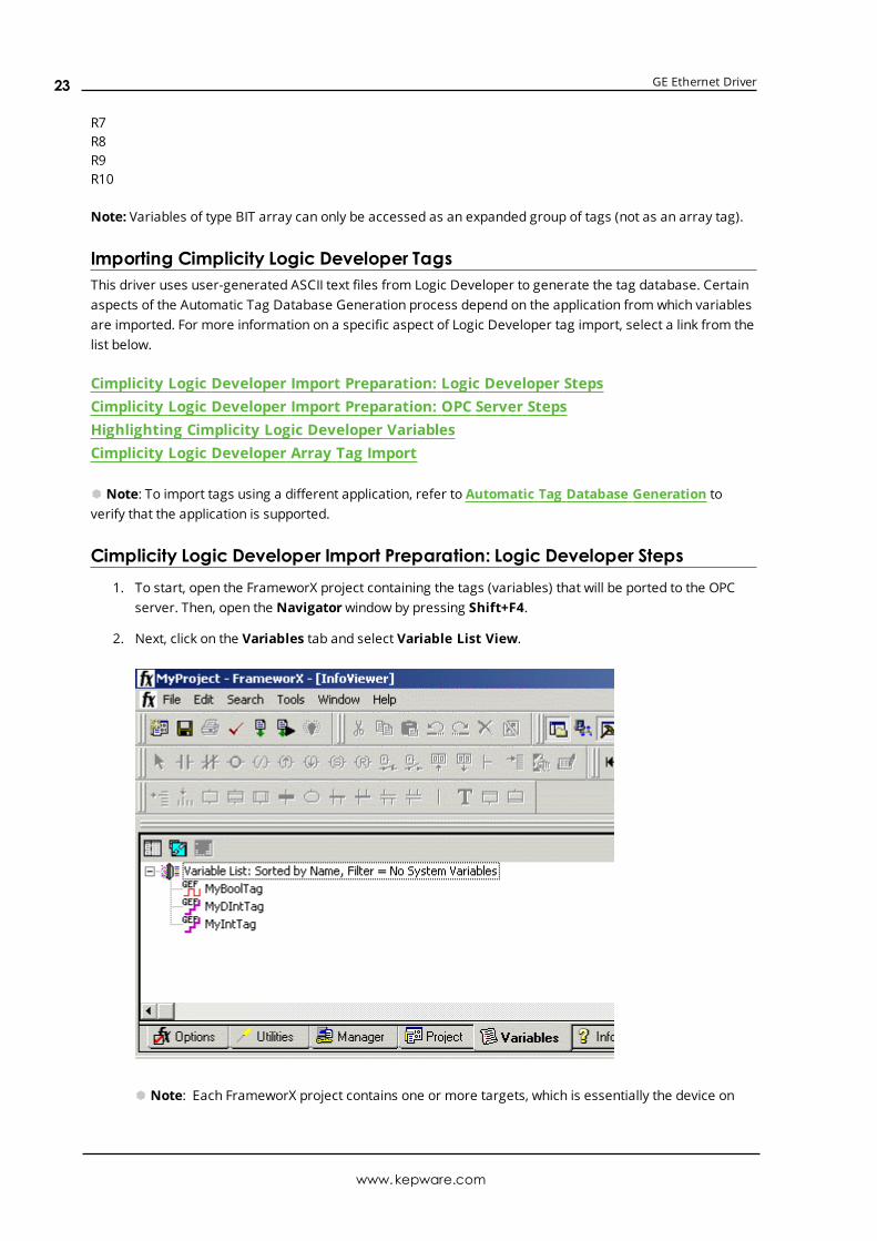
Note: Variables of type BIT array can only be accessed as an expanded group of tags (not as an array tag).
Importing Cimplicity Logic Developer TagsThis driver uses user-generated ASCII text files from Logic Developer to generate the tag database. Certainaspects of the Automatic Tag Database Generation process depend on the application from which variablesare imported. For more information on a specific aspect of Logic Developer tag import, select a link from thelist below.
Cimplicity Logic Developer Import Preparation: Logic Developer StepsCimplicity Logic Developer Import Preparation: OPC Server StepsHighlighting Cimplicity Logic Developer VariablesCimplicity Logic Developer Array Tag Import
à Note: To import tags using a different application, refer to Automatic Tag Database Generation toverify that the application is supported.
Cimplicity Logic Developer Import Preparation: Logic Developer Steps1. To start, open the FrameworX project containing the tags (variables) that will be ported to the OPC
server. Then, open the Navigatorwindow by pressing Shift+F4.
2. Next, click on the Variables tab and select Variable List View.
à Note: Each FrameworX project contains one or more targets, which is essentially the device on
www.kepware.com
23

GE Ethernet Driver
which the application will run. Because variables are created on the target level, a target of interestmust be specified before the variables that will be exportedmay be. In order for the target variablesto be imported, the variables must have GE PLC as the Data Source. To verify this, left-click on thevariable and then look at the Data Source properties in the Inspectorwindow. Internal variables willnot be imported.
3. Next, sort the variables by target by right-clicking on the Variable List and selecting Sort | Target.
4. Then, highlight the tags of interest in the target of interest and click Edit | Copy.
à Note: The highlighted variables should now be copied to the Clipboard.
5. Next, open a word processing program like Notepad or Wordpad. Then, click Edit | Paste.
à Note: The variables on the Clipboard will now be pasted to the document, TAB delimited. Do notmodify the contents: modifications may cause the import to fail.
6. Save the text document with the text extension (.txt) in ANSI form.
7. The variables are now contained within the text document and can be imported into the OPC server.
www.kepware.com
24

GE Ethernet Driver
Cimplicity Logic Developer Import Preparation: OPC Server Steps1. To start, right-click on the device for which tags will be generated and select Device Properties.
Then, open the Variable Import Settings property group.
2. In Variable Import File, enter or browse for the location of the Logic Developer *.txt file newlycreated. Then, click Apply.
3. Next, select the Tag Generation property group. Then, click Create Tags.
4. The OPC server will state in the Event Log that it is attempting to perform a tag import. Whenfinished, it will state that the tag import has completed. All variables exported out of Logic Developerwill appear in the OPC server in the layout discussed in Tag Hierarchy.
5. Once finished, clickOK.
See Also: Variable Import Settings
Highlighting Cimplicity Logic Developer VariablesVariables can be highlighted in Logic Developer in the following ways:
l Single Variable Selecting: To do so, left-click on a variable of interest.
l Pick-n-Choose: To do so, left-click on the first variable of interest. Then, press CTRL while left-clickingon each successive variable of interest. Repeat until all variables of interest are highlighted.
l Selecting a Range of Variables: To do so, left-click on the first variable in the range of interest.Then, press SHIFT while left-clicking on the last variable in the range. All variables in the range will behighlighted.
l Selecting All Variables: To do so, left-click on a variable within the target of interest in the VariableList View. The variable chosen is irrelevant. Then, click Edit | Select All. All variables will behighlighted within that target.
Cimplicity Logic Developer Array Tag ImportArray tags, or individual element breakdowns of array variables, are not supported when importing fromCimplicity Logic Developer.
Importing Proficy Logic Developer TagsThis driver uses user-generated ASCII text files from Proficy Logic Developer to generate the tag database.Certain aspects of the Automatic Tag Database Generation process depend on the application from whichvariables are imported. For more information on a specific aspect of Proficy Logic Developer tag import,select a link from the list below.
Proficy Logic Developer Import Preparation: Logic Developer StepsProficy Logic Developer Import Preparation: OPC Server StepsHighlighting Proficy Logic Developer VariablesProficy Logic Developer Array Tag Import
à Note: To import tags using a different application, refer to Automatic Tag Database Generation toverify that the application is supported.
www.kepware.com
25

GE Ethernet Driver
Proficy Logic Developer Import Preparation: Logic Developer Steps1. To start, open the Proficy Logic Developer project containing the tags (variables) that will be ported to
the OPC server. Then, open the Navigatorwindow by pressing Shift-F4.
2. Next, click on the Variables tab to bring the project's variables to the front. Then, click Variable ListView.
à Note: Each Logic Developer project contains one or more targets, which is essentially the deviceon which the application will run. Because variables are created on the target level, the target ofinterest must be specified before the variables that will be exportedmay be. For the target variablesto be imported, the variables must have GE PLC chosen as the Data Source. To verify this, left-clickon the variable and then look at the Data Source properties in the Inspectorwindow. Internalvariables will not be imported.
3. Next, sort the variables by target by right-clicking on the Variable List header and selecting Sort |Target.
4. To export all of the variables, right-click on the Variable List and click Export.
5. To export selected variables, highlight the tags of interest in the target of interest. Then, right-click onone of the selected variables and click Export.
www.kepware.com
26

GE Ethernet Driver
6. In the Save as Type drop-down list, select Standard Name Form (*.snf) or Comma SeparatedVariable (*.csv) as the export file type. The dialogs should appear as shown below.
www.kepware.com
27

GE Ethernet Driver
7. Once finished, click Save.
Proficy Logic Developer Import Preparation: OPC Server Steps1. To start, right-click on the device for which tags will be generated and select Device Properties.
Then, open the Variable Import Settings property group.
2. In Variable Import File, enter or browse for the location of the export file newly created *.snf or*.csv file. Then, click Apply.
3. Next, select the Tag Generation property group, and then click Create Tags to import variables.Alternatively, use the other settings in that property group to automatically create the database later.
4. The OPC server will state in the Event Log that it is attempting to perform a tag import. Whenfinished, it will state that the tag import has completed. All variables exported out of Logic Developerwill appear in the OPC server in the layout discussed in Tag Hierarchy.
5. Once finished, clickOK.
See Also: Variable Import Settings
Highlighting Proficy Logic Developer VariablesVariables can be highlighted in Logic Developer in the following ways:
l Single Variable Selecting: To do so, left-click on a variable of interest.
l Pick-n-Choose: To do so, left-click on the first variable of interest. Then, press CTRL while left-clickingon each successive variable of interest. Repeat until all variables of interest are highlighted.
l Selecting a Range of Variables: To do so, left-click on the first variable in the range of interest.Then, press SHIFT while left-clicking on the last variable in the range. All variables in the range will behighlighted.
l Selecting All Variables: To do so, left-click on a variable within the target of interest in the VariableList View. The variable chosen is irrelevant. Then, click Edit | Select All. All variables will behighlighted within that target.
www.kepware.com
28

GE Ethernet Driver
Proficy Logic Developer Array Tag ImportArrays of referenced variables and arrays of symbolic variables will be imported differently.
Referenced Variable ArraysArrays of referenced variables will be imported as described in VersaPro Array Tag Import. A group will becreated for each array. Each group will contain a single array tag, plus a number of tags addressing theindividual array elements.
Symbolic Variable ArraysA single array tag will be generated for each symbolic variable array in the import file. All symbolic variablearray tags will be placed in the Symbolic group along with all other symbolic variable tags. The driver will notgenerate tags for BOOL and STRING symbolic variable arrays.
Importing Array Elements (Index)When importing array elements (such as "MyArrayTag[1,2]") into the driver, the '[' and ']' characters will bereplaced with '{' and '}' respectively for internal reasons. The '[' and ']' characters are reserved by this driverfor array notation. While communicating with the PLC at Runtime, however, the replacement will be reversedby the driver to comply with the standard GE syntax.
à See Also: Symbolic Variables
www.kepware.com
29
GE Ethernet Driver
Optimizing CommunicationsThe GE Ethernet Driver has been designed to provide the best performance with the least amount of impacton the system's overall performance. While the GE Ethernet Driver is fast, there are a couple of guidelinesthat can be used in order to control and optimize the application and gain maximum performance.
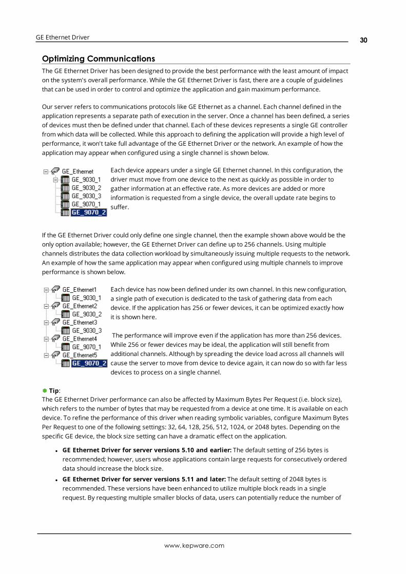
Our server refers to communications protocols like GE Ethernet as a channel. Each channel defined in theapplication represents a separate path of execution in the server. Once a channel has been defined, a seriesof devices must then be defined under that channel. Each of these devices represents a single GE controllerfrom which data will be collected. While this approach to defining the application will provide a high level ofperformance, it won't take full advantage of the GE Ethernet Driver or the network. An example of how theapplicationmay appear when configured using a single channel is shown below.
Each device appears under a single GE Ethernet channel. In this configuration, thedriver must move from one device to the next as quickly as possible in order togather information at an effective rate. As more devices are added or moreinformation is requested from a single device, the overall update rate begins tosuffer.
If the GE Ethernet Driver could only define one single channel, then the example shown above would be theonly option available; however, the GE Ethernet Driver can define up to 256 channels. Using multiplechannels distributes the data collection workload by simultaneously issuing multiple requests to the network.An example of how the same applicationmay appear when configured using multiple channels to improveperformance is shown below.
Each device has now been defined under its own channel. In this new configuration,a single path of execution is dedicated to the task of gathering data from eachdevice. If the application has 256 or fewer devices, it can be optimized exactly howit is shown here.
The performance will improve even if the application has more than 256 devices.While 256 or fewer devices may be ideal, the application will still benefit fromadditional channels. Although by spreading the device load across all channels willcause the server to move from device to device again, it can now do so with far lessdevices to process on a single channel.
à Tip:The GE Ethernet Driver performance can also be affected by Maximum Bytes Per Request (i.e. block size),which refers to the number of bytes that may be requested from a device at one time. It is available on eachdevice. To refine the performance of this driver when reading symbolic variables, configure Maximum BytesPer Request to one of the following settings: 32, 64, 128, 256, 512, 1024, or 2048 bytes. Depending on thespecific GE device, the block size setting can have a dramatic effect on the application.
l GE Ethernet Driver for server versions 5.10 and earlier: The default setting of 256 bytes isrecommended; however, users whose applications contain large requests for consecutively ordereddata should increase the block size.
l GE Ethernet Driver for server versions 5.11 and later: The default setting of 2048 bytes isrecommended. These versions have been enhanced to utilize multiple block reads in a singlerequest. By requesting multiple smaller blocks of data, users can potentially reduce the number of
www.kepware.com
30

GE Ethernet Driver
unnecessary bytes in the response (especially when the requested data is not contiguous inmemory). The Block Size property limits the number of bytes returned for all the blocks.
à See Also: Communications Settings
à Note: For PACSystemModels It is recommended that referenced (mapped) variables and symbolicvariables be placed on separate devices. For more information, refer to Symbolic Variables.
www.kepware.com
31

GE Ethernet Driver
Data Types Description
DataType Description
Boolean Single bit.
Byte Unsigned 8 bit value.
bit 0 is the low bit.bit 7 is the high bit.
Word Unsigned 16 bit value.
bit 0 is the low bit.bit 15 is the high bit.
Short Signed 16 bit value.
bit 0 is the low bit.bit 14 is the high bit.bit 15 is the sign bit.
DWord Unsigned 32 bit value.
bit 0 is the low bit.bit 31 is the high bit.
Long Signed 32 bit value.
bit 0 is the low bit.bit 30 is the high bit.bit 31 is the sign bit.
BCD Two byte packed BCD.
Value range is 0-9999. Behavior is undefined for values beyond this range.
LBCD Four byte packed BCD.
Value range is 0-99999999. Behavior is undefined for values beyond this range.
Float 32 bit floating point value.
The driver interprets two consecutive registers as a floating point value by making the secondregister the high word and the first register the low word.
Double 64 bit floating point value.
The driver interprets four consecutive registers as a floating point value.
String Null terminated ASCII string.
Support includes HiLo LoHi byte order selection.
www.kepware.com
32

GE Ethernet Driver
Address DescriptionsAddress specifications vary depending on the model in use. Select a link from the following list to obtainspecific address information for the model of interest.
PACSystems AddressingSymbolic Variables311313331341350360731732771772781782GE OPENHorner OCSVersaMax AddressingAdvanced AddressingSpecial Items
PACSystems AddressingThe default data types for dynamic tags are shown in bold.
Device Address Range Data Type AccessDiscrete Inputs I00001 to I32768
I00001 to I32761 (every 8th bit)I00001 to I32753 (every 8th bit)
BooleanByteWord, Short, BCD
Read/Write
Discrete Outputs Q00001 to Q32768Q00001 to Q32761 (every 8th bit)Q00001 to Q32753 (every 8th bit)
BooleanByteWord, Short, BCD
Read/Write
Discrete Globals G00001 to G7680G00001 to G7673 (every 8th bit)G00001 to G7665 (every 8th bit)
BooleanByteWord, Short, BCD
Read/Write
Internal Coils M00001 to M32768M00001 to M32761 (every 8th bit)M00001 to M32753 (every 8th bit)
BooleanByteWord, Short, BCD
Read/Write
Temporary Coils T0001 to T1024T0001 to T1017 (every 8th bit)T0001 to T1009 (every 8th bit)
BooleanByteWord, Short, BCD
Read/Write
Status References
(Same for SA, SB, SC)
S001 to S128S001 to S121 (every 8th bit)S001 to S113 (every 8th bit)
BooleanByteWord, Short, BCD
Read Only
www.kepware.com
33

GE Ethernet Driver
Device Address Range Data Type AccessRegister References R1.0 to R32640.15
R00001 to R32640R00001 to R32639R00001 to R32637
BooleanWord, Short, BCDDWord, Long, LBCD,FloatDouble
Read/Write
Analog Inputs AI1.0 to AI32640.15AI00001 to AI32640AI00001 to AI32639AI00001 to AI32637
BooleanWord, Short, BCDDWord, Long, LBCD,FloatDouble
Read/Write
Analog Outputs AQ1.0 to AQ32640.15AQ00001 to AQ32640AQ00001 to AQ32639AQ00001 to AQ32637
BooleanWord, Short, BCDDWord, Long, LBCD,FloatDouble
Read/Write
Program Block Registers* P1.0 to P8192.15P00001 to P8192P00001 to P8191P00001 to P8189
BooleanWord, Short, BCDDWord, Long, LBCD,FloatDouble
Read/Write
SubProgram BlockRegisters**
L00001<SUBPRGM>.0 toL8192<SUBPRGM>.15
L00001<SUBPRGM> toL8192<SUBPRGM>
L00001<SUBPRGM> toL8191<SUBPRGM>
L00001<SUBPRGM> toL8189<SUBPRGM>
Boolean
Word, Short, BCD
DWord, Long, LBCD,Float
Double
Read/Write
Bulk Memory W1.0 to W33554432.15W00001 to W33554432W00001 to W33554431W00001 to W33554429
BooleanWord, Short, BCDDWord, Long, LBCD,FloatDouble
Read/Write
*Program specified in PLC Settings.
**The SubProgram name/Block name <SUBPRGM> must match the name assigned in the PLC. This namecan be found in VersaPro under "Block Properties."
à Note: For more information, refer to "Importing Array Elements (Index)" in Proficy Logic DeveloperArray Tag Import.
à See Also: Symbolic Variables
Advanced Addressing
www.kepware.com
34
GE Ethernet Driver
Bit Access to RegistersDefault Data Type OverrideString Access to RegistersArray Support
Symbolic VariablesA variable is a named storage space for data in the PLC. There are two types of variables: Reference andSymbolic. Descriptions of the variables are as follows:
l Reference Variable: This variable is mapped to a specific I/O or internal register location in the PLC(such as I00001, R00100, and so forth).
l Symbolic Variable: This variable is not mapped to a specific register. The PLC will allocate memoryfor symbolic variables as needed from its managedmemory area. This driver has the ability to readand write to symbolic variables defined in the PLC. Symbolic variables are only available in PACSystems PLCs.
Creating a Symbolic Variable
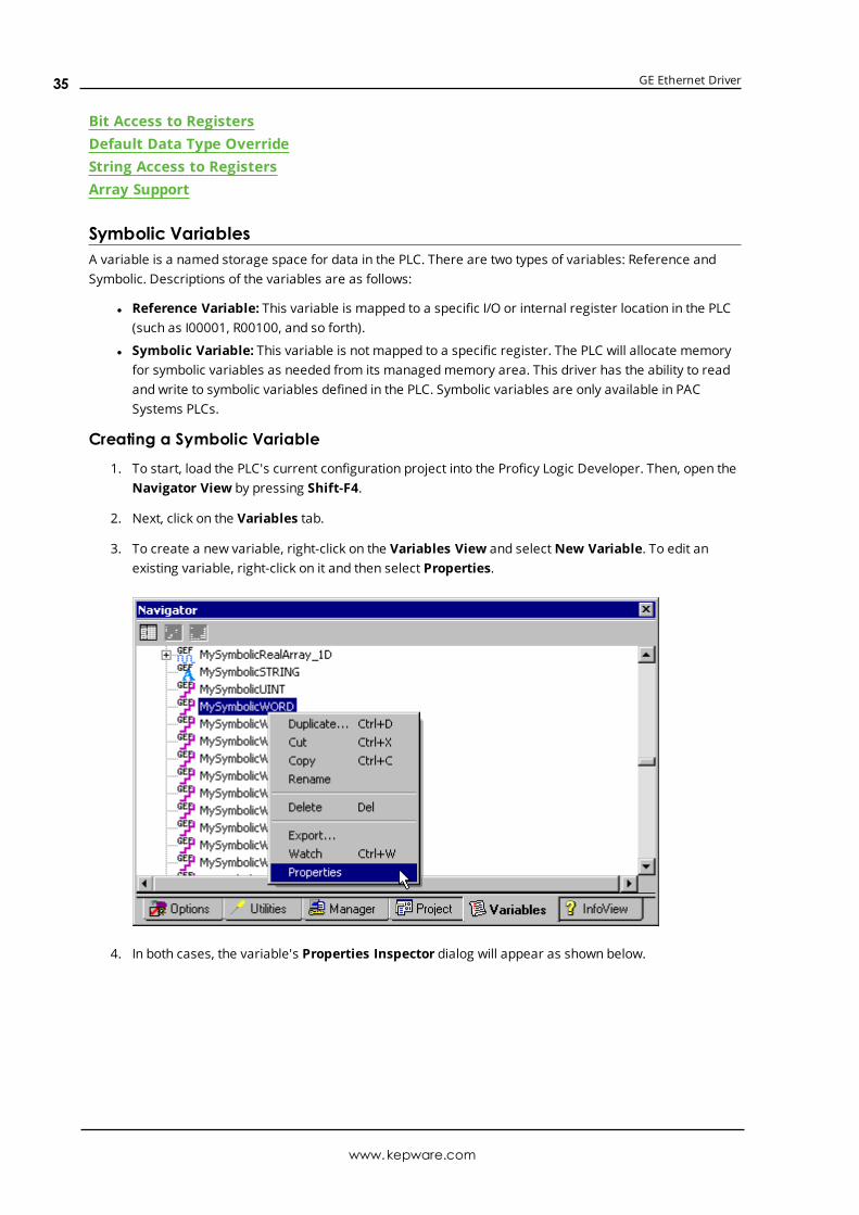
1. To start, load the PLC's current configuration project into the Proficy Logic Developer. Then, open theNavigator View by pressing Shift-F4.
2. Next, click on the Variables tab.
3. To create a new variable, right-click on the Variables View and selectNew Variable. To edit anexisting variable, right-click on it and then select Properties.
4. In both cases, the variable's Properties Inspector dialog will appear as shown below.
www.kepware.com
35

GE Ethernet Driver
à Note: The variable displayed above is symbolic because the Ref Address parameter is left blank.The variable is named "MySymbolicWORD" and has a data type of Word. An array of variables can becreated by setting the Array Dimension 1 parameter to a value greater than zero. The ArrayDimension 2 parameter will appear in the variable inspector if Array Dimension 1 is set. A singledimension array is defined when Array Dimension 2 is left at zero. The total number of arrayelements is limited by theMaximum Bytes Per Request property in Device Properties. For moreinformation, refer to Device Setup.
à For a symbolic variable to be visible to this driver, Publishmust be set to External.
5. Next, download the modified project to the PLC.
6. To access a symbolic variable with the OPC server, create a tag whose address references thevariable by name. It must be preceded by the "!" character.
ExamplesThe syntax for addressing array elements uses curly brackets. These characters are specific to this server:other servers or products may access array elements using square brackets instead. The appropriateconversion will be done internally by the driver at Runtime while communicating with the PLC. For addressingpurposes, users must utilize curly brackets: square brackets are reserved by this driver for array notation.
à Important: The tag must be assigned a data type that is compatible with the data type of the symbolicvariable; however, if the tag address references a bit of the symbolic variable, then the tag data type mustbe Boolean. Furthermore, the dimensions of the array tag must be the same as the variable. The tagproperties can only be validated during Runtime.
1. !MySymbolicArray1D [4] addresses the symbolic variable named "MySymbolicArray1D," which isassumed to have its Array Dimension 1 property set to 4.
2. !MySymbolicArray1D {3} addresses the index (3) of the above 1D symbolic array variable"MySymbolicArray1D."
www.kepware.com
36

GE Ethernet Driver
3. !MySymbolicArray2D [3][4] addresses the symbolic variable named "MySymbolicArray2D," which isassumed to have its Array Dimension 1 property set to 3, and its "Array Dimension 2" property set to4.
4. !MySymbolicArray2D {2,3} addresses the index (2,3) of the above 2D symbolic array variable"MySymbolicArray2D."
5. !MySymbolicVariable.5 addresses the bit index 5 of the symbolic variable named"MySymbolicVariable."
6. !MySymbolicVariable.30 addresses the bit index 30 of the symbolic variable named"MySymbolicVariable," which is assumed to have a native data type of Dint or DWord.
7. !MySymbolicArray{3}.8 addresses the bit index 8 of the element at index 3 of the symbolic arraynamed "MySymbolicArray," which is assumed to have a native data type of Int, Uint, Word, Dint, orDWord.
8. !MySymbolicArray{3,2}.8 addresses the bit index 8 of the element at index 2 of the fourth array of thesymbolic array named "MySymbolicArray," which is assumed to have a native data type of Int, Uint,Word, Dint, or DWord.
9. !MySymbolicUDTArray{5}.MyUDTMember.7 addresses the bit index 7 of the User Defined Type(UDT) member variable named "MyUDTMember" of the element at index 5 of the symbolic arrayvariable named "MySymbolicUDTArray."
10. !MyUDT.MyUDTMember.16 addresses the bit index 16 of the symbolic variable named"MyUDTMember" that is part of a UDT named "MyUDT." The MyUDTMember variable is assumed tohave a native data type of Dint or DWord.
Compatible Data TypesThe driver assigns a default type of Word to tags that use Symbolic Addressing; however, Boolean is thedefault data type assigned to the tags that have a bit index appended to the symbolic address.
Native Type (Device) Compatible Types (Server)Bool Bool (no arrays)
Byte Byte, Char
Int Word, Short
Uint Word, Short
Word Word, Short
Dint DWord, Long
DWord DWord, Long
Real Float, Double
LReal Double
String String (no arrays)
à Note: Users should be sure to specify an appropriate data type override for each dynamic tag. DynamicTags are only defined in the client application and are created in the server on demand by the client. Theirdata type can be specified by appending one of the following strings to the item name: @Boolean, @Byte,@Char, @Short, @Word, @Long, @DWord, @Float or @String. For more information, refer to the OPC serverhelp file.
Example
www.kepware.com
37

GE Ethernet Driver
ItemName = "Channel1.Device1.!MySymbolicWordVariable @DWord"
Performance ConsiderationsBlock SizeThis driver attempts to optimize performance by reading blocks of symbolic variable memory. For the GEEthernet Driver released in server versions 5.10 and earlier, it was generally faster to read a single largeblock of data (such as where only the first and last few bytes were needed to update two tags) than it was toperform two separate reads for the few bytes needed for each tag. The amount of symbolic variablememory read per request was limited by theMaximum Bytes Per Request property located in DeviceProperties. As such, it was typically advantageous to maximize this setting.
In some cases, however, performance would increase by reducing that setting. An example of this is whenthe variables being readmost frequently were widely scattered in the controller's managedmemory area.Users cannot control the mapping of symbolic variable data in the controller's memory: mapping largelydepends on when the variables were added to the configuration project. As such, if performance was aprimary concern for the GE Ethernet Driver in those server versions, it was recommended that usersexperiment with the Maximum Bytes Per Request property.
The GE Ethernet Driver released in server version 5.11 has been enhanced to improve performance byallowing multiple small blocks in a single request. Only the desired bytes will be requested when the data isnot contiguous, and a single request may include multiple small block requests. The Maximum Bytes PerRequest property will limit the total number of bytes in the response, but not the number of bytes in theindividual blocks. As such, using this value's maximum setting will likely improve performance.
Multi-Item WritesThis driver will also attempt to optimize performance by performing multi-item writes. The number of tagsincluded in a request is limited by the Maximum Bytes Per Request property. Unlike block reads, thevariables' location in the controller's memory is of little consequence. Writes can further be optimized withtheWrite Optimizations properties located in Channel Properties.
à Note: If the driver finds that the variable named in a tag's address does not exist in the controller (or if itdoes not match the data type or array dimension), its OPC quality will be set to Bad. The driver will continueto check the controller for the named variable should a new configuration be downloaded. It isrecommended that users do not utilize those tags in the client applications because they will remain invalid.
311 AddressingThe default data types for dynamic tags are shown in bold.
Device Address Range Data Type* AccessDiscrete Inputs I001 to I512
I001 to I505 (every 8th bit)I001 to I497 (every 8th bit)
BooleanByteWord, Short, BCD
Read/Write
Discrete Outputs Q001 to Q512Q001 to Q505 (every 8th bit)Q001 to Q497 (every 8th bit)
BooleanByteWord, Short, BCD
Read/Write
Discrete Globals G0001 to G1280G0001 to G1273 (every 8th bit)G0001 to G1265 (every 8th bit)
BooleanByteWord, Short, BCD
Read/Write
Internal Coils M0001 to M1024M0001 to M1017 (every 8th bit)
BooleanByte
Read/Write
www.kepware.com
38
GE Ethernet Driver
Device Address Range Data Type* AccessM0001 to M1009 (every 8th bit) Word, Short, BCD
Temporary Coils T001 to T256T001 to T249 (every 8th bit)T001 to T241 (every 8th bit)
BooleanByteWord, Short, BCD
Read/Write
Status References
(Same for SA, SB, SC)
S01 to S32S01 to S25 (every 8th bit)S01 to S17 (every 8th bit)
BooleanByteWord, Short, BCD
Read Only
Register References R1.0 to R512.15R001 to R512R001 to R511R001 to R509
BooleanWord, Short, BCDDWord, Long, LBCD, FloatDouble
Read/Write
Analog Inputs AI1.0 to AI64.15AI01 to AI64AI01 to AI63AI01 to AI61
BooleanWord, Short, BCDDWord, Long, LBCD, FloatDouble
Read/Write
Analog Outputs AQ1.0 to AQ032.15AQ001 to AQ032AQ001 to AQ031AQ001 to AQ029
BooleanWord, Short, BCDDWord, Long, LBCD, FloatDouble
Read/Write
Special Items**(PLC Status, Time, etc)
*Default data type of Boolean becomes Byte when an array specification is given.**Ã See Also: Special Items
Advanced AddressingBit Access to RegistersDefault Data Type OverrideString Access to RegistersArray Support
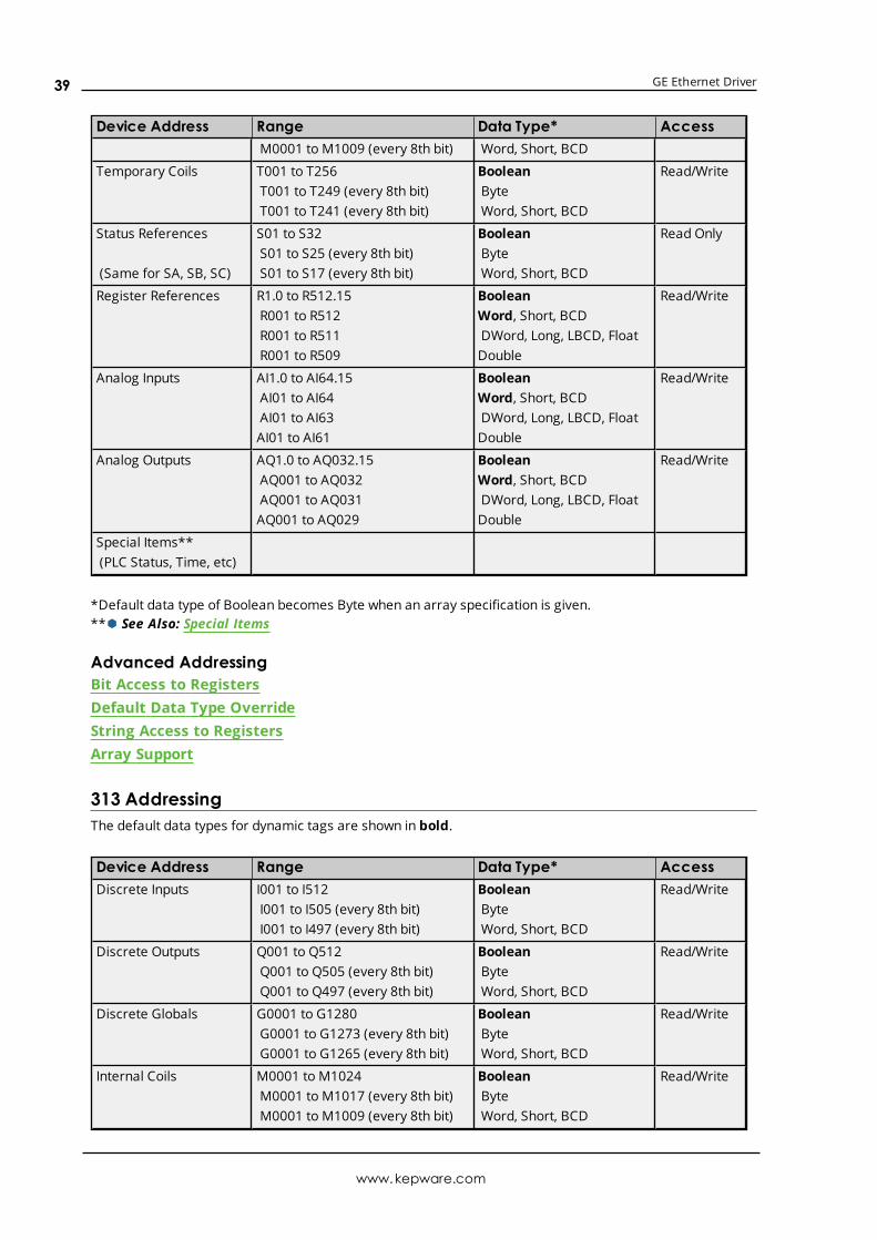
313 AddressingThe default data types for dynamic tags are shown in bold.
Device Address Range Data Type* AccessDiscrete Inputs I001 to I512
I001 to I505 (every 8th bit)I001 to I497 (every 8th bit)
BooleanByteWord, Short, BCD
Read/Write
Discrete Outputs Q001 to Q512Q001 to Q505 (every 8th bit)Q001 to Q497 (every 8th bit)
BooleanByteWord, Short, BCD
Read/Write
Discrete Globals G0001 to G1280G0001 to G1273 (every 8th bit)G0001 to G1265 (every 8th bit)
BooleanByteWord, Short, BCD
Read/Write
Internal Coils M0001 to M1024M0001 to M1017 (every 8th bit)M0001 to M1009 (every 8th bit)
BooleanByteWord, Short, BCD
Read/Write
www.kepware.com
39

GE Ethernet Driver
Device Address Range Data Type* AccessTemporary Coils T001 to T256
T001 to T249 (every 8th bit)T001 to T241 (every 8th bit)
BooleanByteWord, Short, BCD
Read/Write
Status References
(Same for SA, SB, SC)
S01 to S32S01 to S25 (every 8th bit)S01 to S17 (every 8th bit)
BooleanByteWord, Short, BCD
Read Only
Register References R1.0 to R1024.15R001 to R1024R001 to R1023R001 to R1021
BooleanWord, Short, BCDDWord, Long, LBCD, FloatDouble
Read/Write
Analog Inputs AI1.0 to AI64.15AI01 to AI64AI01 to AI63AI01 to AI61
BooleanWord, Short, BCDDWord, Long, LBCD, FloatDouble
Read/Write
Analog Outputs AQ1.0 to AQ032.15AQ001 to AQ032AQ001 to AQ031AQ001 to AQ029
BooleanWord, Short, BCDDWord, Long, LBCD, FloatDouble
Read/Write
Special Items**(PLC Status, Time, etc)
*Default data type of Boolean becomes Byte when an array specification is given.**Ã See Also: Special Items
Advanced AddressingBit Access to RegistersDefault Data Type OverrideString Access to RegistersArray Support
331 AddressingThe default data types for dynamic tags are shown in bold.
Device Address Range Data Type* AccessDiscrete Inputs I001 to I512
I001 to I505 (every 8th bit)I001 to I497 (every 8th bit)
BooleanByteWord, Short, BCD
Read/Write
Discrete Outputs Q001 to Q512Q001 to Q505 (every 8th bit)Q001 to Q497 (every 8th bit)
BooleanByteWord, Short, BCD
Read/Write
Discrete Globals G0001 to G1280G0001 to G1273 (every 8th bit)G0001 to G1265 (every 8th bit)
BooleanByteWord, Short, BCD
Read/Write
Internal Coils M0001 to M1024M0001 to M1017 (every 8th bit)M0001 to M1009 (every 8th bit)
BooleanByteWord, Short, BCD
Read/Write
Temporary Coils T001 to T256 Boolean Read/Write
www.kepware.com
40

GE Ethernet Driver
Device Address Range Data Type* AccessT001 to T249 (every 8th bit)T001 to T241 (every 8th bit)
ByteWord, Short, BCD
Status References
(Same for SA, SB, SC)
S01 to S32S01 to S25 (every 8th bit)S01 to S17 (every 8th bit)
BooleanByteWord, Short, BCD
Read Only
Register References R1.0 to R2048.15R0001 to R2048R0001 to R2047R0001 to R2045
BooleanWord, Short, BCDDWord, Long, LBCD, FloatDouble
Read/Write
Analog Inputs AI1.0 to AI128.15AI001 to AI128AI001 to AI127AI001 to AI125
BooleanWord, Short, BCDDWord, Long, LBCD, FloatDouble
Read/Write
Analog Outputs AQ1.0 to AQ64.15AQ01 to AQ64AQ01 to AQ63AQ01 to AQ61
BooleanWord, Short, BCDDWord, Long, LBCD, FloatDouble
Read/Write
Special Items**(PLC Status, Time, etc)
*Default data type of Boolean becomes Byte when an array specification is given.**Ã See Also: Special Items.
Advanced AddressingBit Access to RegistersDefault Data Type OverrideString Access to RegistersArray Support
341 AddressingThe default data types for dynamic tags are shown in bold.
Device Address Range Data Type* AccessDiscrete Inputs I001 to I512
I001 to I505 (every 8th bit)I001 to I497 (every 8th bit)
BooleanByteWord, Short, BCD
Read/Write
Discrete Outputs Q001 to Q512Q001 to Q505 (every 8th bit)Q001 to Q497 (every 8th bit)
BooleanByteWord, Short, BCD
Read/Write
Discrete Globals G0001 to G1280G0001 to G1273 (every 8th bit)G0001 to G1265 (every 8th bit)
BooleanByteWord, Short, BCD
Read/Write
Internal Coils M0001 to M1024M0001 to M1017 (every 8th bit)M0001 to M1009 (every 8th bit)
BooleanByteWord, Short, BCD
Read/Write
Temporary Coils T001 to T256T001 to T249 (every 8th bit)
BooleanByte
Read/Write
www.kepware.com
41
GE Ethernet Driver
Device Address Range Data Type* AccessT001 to T241 (every 8th bit) Word, Short, BCD
Status References
(Same for SA, SB, SC)
S01 to S32S01 to S25 (every 8th bit)S01 to S17 (every 8th bit)
BooleanByteWord, Short, BCD
Read Only
Register References R1.0 to R9999.15R0001 to R9999R0001 to R9998R0001 to R9996
BooleanWord, Short, BCDDWord, Long, LBCD, FloatDouble
Read/Write
Analog Inputs AI1.0 to AI1024.15AI0001 to AI1024AI0001 to AI1023AI0001 to AI1021
BooleanWord, Short, BCDDWord, Long, LBCD, FloatDouble
Read/Write
Analog Outputs AQ1.0 to AQ256.15AQ0001 to AQ256AQ0001 to AQ255AQ0001 to AQ253
BooleanWord, Short, BCDDWord, Long, LBCD, FloatDouble
Read/Write
Special Items**(PLC Status, Time, etc)
*Default data type of Boolean becomes Byte when an array specification is given.**Ã See Also: Special Items.
Advanced AddressingBit Access to RegistersDefault Data Type OverrideString Access to RegistersArray Support
350 AddressingThe default data types for dynamic tags are shown in bold.
Device Address Range Data Type* AccessDiscrete Inputs I0001 to I2048
I0001 to I2041 (every 8th bit)I0001 to I2033 (every 8th bit)
BooleanByteWord, Short, BCD
Read/Write
Discrete Outputs Q0001 to Q2048Q0001 to Q2041 (every 8th bit)Q0001 to Q2033 (every 8th bit)
BooleanByteWord, Short, BCD
Read/Write
Discrete Globals G0001 to G1280G0001 to G1273 (every 8th bit)G0001 to G1265 (every 8th bit)
BooleanByteWord, Short, BCD
Read/Write
Internal Coils M0001 to M4096M0001 to M4089 (every 8th bit)M0001 to M4081 (every 8th bit)
BooleanByteWord, Short, BCD
Read/Write
Temporary Coils T001 to T256T001 to T249 (every 8th bit)T001 to T241 (every 8th bit)
BooleanByteWord, Short, BCD
Read/Write
www.kepware.com
42
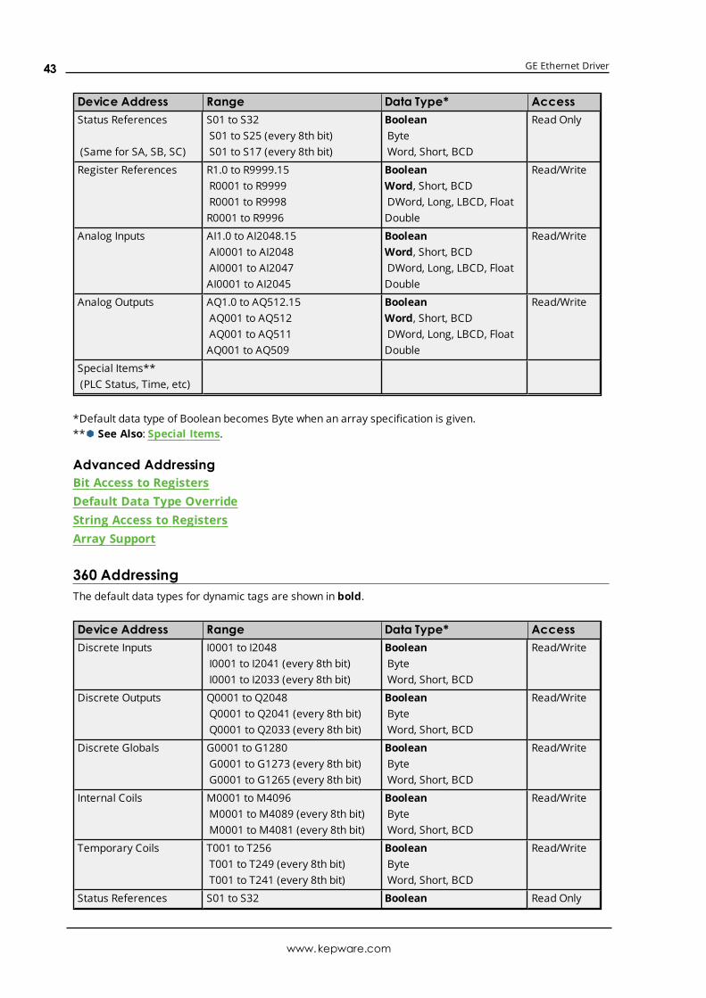
GE Ethernet Driver
Device Address Range Data Type* AccessStatus References
(Same for SA, SB, SC)
S01 to S32S01 to S25 (every 8th bit)S01 to S17 (every 8th bit)
BooleanByteWord, Short, BCD
Read Only
Register References R1.0 to R9999.15R0001 to R9999R0001 to R9998R0001 to R9996
BooleanWord, Short, BCDDWord, Long, LBCD, FloatDouble
Read/Write
Analog Inputs AI1.0 to AI2048.15AI0001 to AI2048AI0001 to AI2047AI0001 to AI2045
BooleanWord, Short, BCDDWord, Long, LBCD, FloatDouble
Read/Write
Analog Outputs AQ1.0 to AQ512.15AQ001 to AQ512AQ001 to AQ511AQ001 to AQ509
BooleanWord, Short, BCDDWord, Long, LBCD, FloatDouble
Read/Write
Special Items**(PLC Status, Time, etc)
*Default data type of Boolean becomes Byte when an array specification is given.**Ã See Also: Special Items.
Advanced AddressingBit Access to RegistersDefault Data Type OverrideString Access to RegistersArray Support
360 AddressingThe default data types for dynamic tags are shown in bold.
Device Address Range Data Type* AccessDiscrete Inputs I0001 to I2048
I0001 to I2041 (every 8th bit)I0001 to I2033 (every 8th bit)
BooleanByteWord, Short, BCD
Read/Write
Discrete Outputs Q0001 to Q2048Q0001 to Q2041 (every 8th bit)Q0001 to Q2033 (every 8th bit)
BooleanByteWord, Short, BCD
Read/Write
Discrete Globals G0001 to G1280G0001 to G1273 (every 8th bit)G0001 to G1265 (every 8th bit)
BooleanByteWord, Short, BCD
Read/Write
Internal Coils M0001 to M4096M0001 to M4089 (every 8th bit)M0001 to M4081 (every 8th bit)
BooleanByteWord, Short, BCD
Read/Write
Temporary Coils T001 to T256T001 to T249 (every 8th bit)T001 to T241 (every 8th bit)
BooleanByteWord, Short, BCD
Read/Write
Status References S01 to S32 Boolean Read Only
www.kepware.com
43

GE Ethernet Driver
Device Address Range Data Type* Access
(Same for SA, SB, SC)S01 to S25 (every 8th bit)S01 to S17 (every 8th bit)
ByteWord, Short, BCD
Register References R1.0 to R32768.15R00001 to R32768R00001 to R32767R00001 to R32765
BooleanWord, Short, BCDDWord, Long, LBCD, FloatDouble
Read/Write
Analog Inputs AI1.0 to AI2048.15AI0001 to AI2048AI0001 to AI2047AI0001 to AI2045
BooleanWord, Short, BCDDWord, Long, LBCD, FloatDouble
Read/Write
Analog Outputs AQ1.0 to AQ512.15AQ001 to AQ512AQ001 to AQ511AQ001 to AQ509
BooleanWord, Short, BCDDWord, Long, LBCD, FloatDouble
Read/Write
Special Items**(PLC Status, Time, etc)
*Default data type of Boolean becomes Byte when an array specification is given.**Ã See Also: Special Items.
Advanced AddressingBit Access to RegistersDefault Data Type OverrideString Access to RegistersArray Support
731 AddressingThe default data types for dynamic tags are shown in bold.
Device Address Range Data Type* AccessDiscrete Inputs I001 to I512
I001 to I505 (every 8th bit)I001 to I497 (every 8th bit)
BooleanByteWord, Short, BCD
Read/Write
Discrete Outputs Q001 to Q512Q001 to Q505 (every 8th bit)Q001 to Q497 (every 8th bit)
BooleanByteWord, Short, BCD
Read/Write
Discrete Globals G0001 to G1280G0001 to G1273 (every 8th bit)G0001 to G1265 (every 8th bit)
BooleanByteWord, Short, BCD
Read/Write
Internal Coils M0001 to M2048M0001 to M2041 (every 8th bit)M0001 to M2033 (every 8th bit)
BooleanByteWord, Short, BCD
Read/Write
Temporary Coils T001 to T256T001 to T249 (every 8th bit)T001 to T241 (every 8th bit)
BooleanByteWord, Short, BCD
Read/Write
Status References S001 to S128S001 to S121 (every 8th bit)
BooleanByte
Read Only
www.kepware.com
44

GE Ethernet Driver
Device Address Range Data Type* Access(Same for SA, SB, SC) S001 to S113 (every 8th bit) Word, Short, BCD
Register References R1.0 to R16384.15R00001 to R16384R00001 to R16383R00001 to R16381
BooleanWord, Short, BCDDWord, Long, LBCD,FloatDouble
Read/Write
Program BlockRegisters***
P1.0 to P16384.15P00001 to P16384P00001 to P16383P00001 to P16381
BooleanWord, Short, BCDDWord, Long, LBCD,FloatDouble
Read/Write
SubProgram BlockRegisters**
L00001<SUBPRGM>.0 toL16384<SUBPRGM>.15
L00001<SUBPRGM> toL16384<SUBPRGM>
L00001<SUBPRGM> toL16383<SUBPRGM>
L00001<SUBPRGM> toL16381<SUBPRGM>
Boolean
Word, Short, BCD
DWord, Long, LBCD,Float
Double
Read/Write
Analog Inputs AI1.0 to AI8192.15AI0001 to AI8192AI0001 to AI8191AI0001 to AI8189
BooleanWord, Short, BCDDWord, Long, LBCD,FloatDouble
Read/Write
Analog Outputs AQ1.0 to AQ8192.15AQ0001 to AQ8192AQ0001 to AQ8191AQ0001 to AQ8189
BooleanWord, Short, BCDDWord, Long, LBCD,FloatDouble
Read/Write
Special Items****(PLC Status, Time, etc)
*Default data type of Boolean becomes Byte when an array specification is given.**The SubProgram name/Block name <SUBPRGM> must match the name assigned in the PLC. This namecan be found in VersaPro under Block Properties.***Program specified in PLC Settings.****Ã See Also: Special Items.
Advanced AddressingBit Access to RegistersDefault Data Type OverrideString Access to RegistersArray Support
www.kepware.com
45

GE Ethernet Driver
732 AddressingThe default data types for dynamic tags are shown in bold.
Device Address Range Data Type* AccessDiscrete Inputs I001 to I512
I001 to I505 (every 8th bit)I001 to I497 (every 8th bit)
BooleanByteWord, Short, BCD
Read/Write
Discrete Outputs Q001 to Q512Q001 to Q505 (every 8th bit)Q001 to Q497 (every 8th bit)
BooleanByteWord, Short, BCD
Read/Write
Discrete Globals G0001 to G1280G0001 to G1273 (every 8th bit)G0001 to G1265 (every 8th bit)
BooleanByteWord, Short, BCD
Read/Write
Internal Coils M0001 to M2048M0001 to M2041 (every 8th bit)M0001 to M2033 (every 8th bit)
BooleanByteWord, Short, BCD
Read/Write
Temporary Coils T001 to T256T001 to T249 (every 8th bit)T001 to T241 (every 8th bit)
BooleanByteWord, Short, BCD
Read/Write
Status References
(Same for SA, SB, SC)
S001 to S128S001 to S121 (every 8th bit)S001 to S113 (every 8th bit)
BooleanByteWord, Short, BCD
Read Only
Register References R1.0 to R16384.15R00001 to R16384R00001 to R16383R00001 to R16381
BooleanWord, Short, BCDDWord, Long, LBCD,FloatDouble
Read/Write
Program BlockRegisters***
P1.0 to P16384.15P00001 to P16384P00001 to P16383P00001 to P16381
BooleanWord, Short, BCDDWord, Long, LBCD,FloatDouble
Read/Write
SubProgram BlockRegisters**
L00001<SUBPRGM>.0 toL16384<SUBPRGM>.15
L00001<SUBPRGM> toL16384<SUBPRGM>
L00001<SUBPRGM> toL16383<SUBPRGM>
L00001<SUBPRGM> toL16381<SUBPRGM>
Boolean
Word, Short, BCD
DWord, Long, LBCD,Float
Double
Read/Write
Analog Inputs AI1.0 to AI8192.15AI0001 to AI8192AI0001 to AI8191AI0001 to AI8189
BooleanWord, Short, BCDDWord, Long, LBCD,FloatDouble
Read/Write
www.kepware.com
46
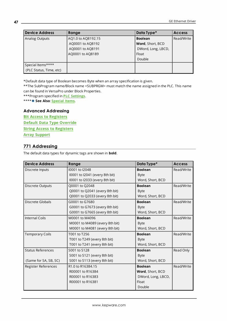
GE Ethernet Driver
Device Address Range Data Type* AccessAnalog Outputs AQ1.0 to AQ8192.15
AQ0001 to AQ8192AQ0001 to AQ8191AQ0001 to AQ8189
BooleanWord, Short, BCDDWord, Long, LBCD,FloatDouble
Read/Write
Special Items****(PLC Status, Time, etc)
*Default data type of Boolean becomes Byte when an array specification is given.**The SubProgram name/Block name <SUBPRGM> must match the name assigned in the PLC. This namecan be found in VersaPro under Block Properties.***Program specified in PLC Settings.****Ã See Also: Special Items.
Advanced AddressingBit Access to RegistersDefault Data Type OverrideString Access to RegistersArray Support
771 AddressingThe default data types for dynamic tags are shown in bold.
Device Address Range Data Type* AccessDiscrete Inputs I0001 to I2048
I0001 to I2041 (every 8th bit)I0001 to I2033 (every 8th bit)
BooleanByteWord, Short, BCD
Read/Write
Discrete Outputs Q0001 to Q2048Q0001 to Q2041 (every 8th bit)Q0001 to Q2033 (every 8th bit)
BooleanByteWord, Short, BCD
Read/Write
Discrete Globals G0001 to G7680G0001 to G7673 (every 8th bit)G0001 to G7665 (every 8th bit)
BooleanByteWord, Short, BCD
Read/Write
Internal Coils M0001 to M4096M0001 to M4089 (every 8th bit)M0001 to M4081 (every 8th bit)
BooleanByteWord, Short, BCD
Read/Write
Temporary Coils T001 to T256T001 to T249 (every 8th bit)T001 to T241 (every 8th bit)
BooleanByteWord, Short, BCD
Read/Write
Status References
(Same for SA, SB, SC)
S001 to S128S001 to S121 (every 8th bit)S001 to S113 (every 8th bit)
BooleanByteWord, Short, BCD
Read Only
Register References R1.0 to R16384.15R00001 to R16384R00001 to R16383R00001 to R16381
BooleanWord, Short, BCDDWord, Long, LBCD,FloatDouble
Read/Write
www.kepware.com
47

GE Ethernet Driver
Device Address Range Data Type* AccessProgram BlockRegisters***
P1.0 to P16384.15P00001 to P16384P00001 to P16383P00001 to P16381
BooleanWord, Short, BCDDWord, Long, LBCD,FloatDouble
Read/Write
SubProgram BlockRegisters**
L00001<SUBPRGM>.0 toL16384<SUBPRGM>.15
L00001<SUBPRGM> toL16384<SUBPRGM>
L00001<SUBPRGM> toL16383<SUBPRGM>
L00001<SUBPRGM> toL16381<SUBPRGM>
Boolean
Word, Short, BCD
DWord, Long, LBCD,Float
Double
Read/Write
Analog Inputs AI1.0 to AI8192.15AI0001 to AI8192AI0001 to AI8191AI0001 to AI8189
BooleanWord, Short, BCDDWord, Long, LBCD,FloatDouble
Read/Write
Analog Outputs AQ1.0 to AQ8192.15AQ0001 to AQ8192AQ0001 to AQ8191AQ0001 to AQ8189
BooleanWord, Short, BCDDWord, Long, LBCD,FloatDouble
Read/Write
Special Items****(PLC Status, Time, etc)
*Default data type of Boolean becomes Byte when an array specification is given.**The SubProgram name/Block name <SUBPRGM> must match the name assigned in the PLC. This namecan be found in VersaPro under Block Properties.***Program specified in PLC Settings.****Ã See Also: Special Items.
Advanced AddressingBit Access to RegistersDefault Data Type OverrideString Access to RegistersArray Support
772 AddressingThe default data types for dynamic tags are shown in bold.
Device Address Range Data Type* AccessDiscrete Inputs I0001 to I2048
I0001 to I2041 (every 8th bit)I0001 to I2033 (every 8th bit)
BooleanByteWord, Short, BCD
Read/Write
www.kepware.com
48
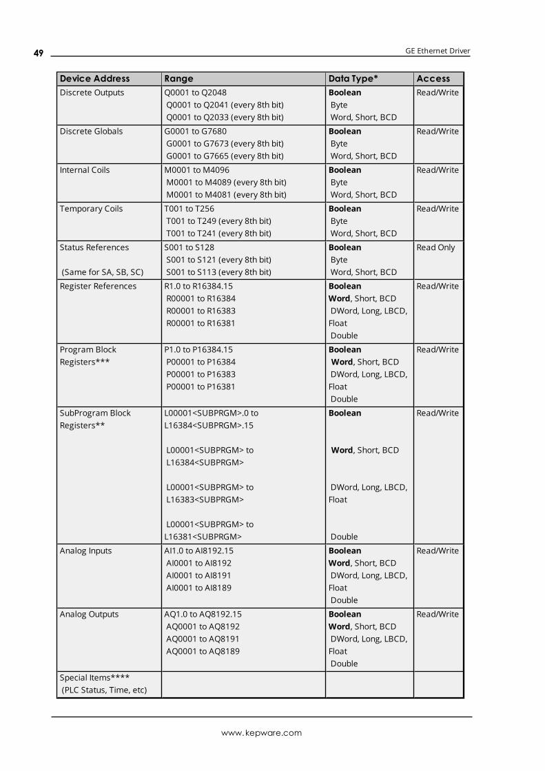
GE Ethernet Driver
Device Address Range Data Type* AccessDiscrete Outputs Q0001 to Q2048
Q0001 to Q2041 (every 8th bit)Q0001 to Q2033 (every 8th bit)
BooleanByteWord, Short, BCD
Read/Write
Discrete Globals G0001 to G7680G0001 to G7673 (every 8th bit)G0001 to G7665 (every 8th bit)
BooleanByteWord, Short, BCD
Read/Write
Internal Coils M0001 to M4096M0001 to M4089 (every 8th bit)M0001 to M4081 (every 8th bit)
BooleanByteWord, Short, BCD
Read/Write
Temporary Coils T001 to T256T001 to T249 (every 8th bit)T001 to T241 (every 8th bit)
BooleanByteWord, Short, BCD
Read/Write
Status References
(Same for SA, SB, SC)
S001 to S128S001 to S121 (every 8th bit)S001 to S113 (every 8th bit)
BooleanByteWord, Short, BCD
Read Only
Register References R1.0 to R16384.15R00001 to R16384R00001 to R16383R00001 to R16381
BooleanWord, Short, BCDDWord, Long, LBCD,FloatDouble
Read/Write
Program BlockRegisters***
P1.0 to P16384.15P00001 to P16384P00001 to P16383P00001 to P16381
BooleanWord, Short, BCDDWord, Long, LBCD,FloatDouble
Read/Write
SubProgram BlockRegisters**
L00001<SUBPRGM>.0 toL16384<SUBPRGM>.15
L00001<SUBPRGM> toL16384<SUBPRGM>
L00001<SUBPRGM> toL16383<SUBPRGM>
L00001<SUBPRGM> toL16381<SUBPRGM>
Boolean
Word, Short, BCD
DWord, Long, LBCD,Float
Double
Read/Write
Analog Inputs AI1.0 to AI8192.15AI0001 to AI8192AI0001 to AI8191AI0001 to AI8189
BooleanWord, Short, BCDDWord, Long, LBCD,FloatDouble
Read/Write
Analog Outputs AQ1.0 to AQ8192.15AQ0001 to AQ8192AQ0001 to AQ8191AQ0001 to AQ8189
BooleanWord, Short, BCDDWord, Long, LBCD,FloatDouble
Read/Write
Special Items****(PLC Status, Time, etc)
www.kepware.com
49

GE Ethernet Driver
*Default data type of Boolean becomes Byte when an array specification is given.**The SubProgram name/Block name <SUBPRGM> must match the name assigned in the PLC. This namecan be found in VersaPro under Block Properties.***Program specified in PLC Settings.****Ã See Also: Special Items.
Advanced AddressingBit Access to RegistersDefault Data Type OverrideString Access to RegistersArray Support
781 AddressingThe default data types for dynamic tags are shown in bold.
Device Address Range Data Type* AccessDiscrete Inputs I00001 to I12288
I00001 to I12281 (every 8th bit)I00001 to I12273 (every 8th bit)
BooleanByteWord, Short, BCD
Read/Write
Discrete Outputs Q00001 to Q12288Q00001 to Q12281 (every 8th bit)Q00001 to Q12273 (every 8th bit)
BooleanByteWord, Short, BCD
Read/Write
Discrete Globals G0001 to G7680G0001 to G7673 (every 8th bit)G0001 to G7665 (every 8th bit)
BooleanByteWord, Short, BCD
Read/Write
Internal Coils M00001 to M12288M00001 to M12281 (every 8th bit)M00001 to M12273 (every 8th bit)
BooleanByteWord, Short, BCD
Read/Write
Temporary Coils T001 to T256T001 to T249 (every 8th bit)T001 to T241 (every 8th bit)
BooleanByteWord, Short, BCD
Read/Write
Status References
(Same for SA, SB, SC)
S001 to S128S001 to S121 (every 8th bit)S001 to S113 (every 8th bit)
BooleanByteWord, Short, BCD
Read Only
Register References R1.0 to R16384.15R00001 to R16384R00001 to R16383R00001 to R16381
BooleanWord, Short, BCDDWord, Long, LBCD,FloatDouble
Read/Write
Program BlockRegisters***
P1.0 to P16384.15P00001 to P16384P00001 to P16383P00001 to P16381
BooleanWord, Short, BCDDWord, Long, LBCD,FloatDouble
Read/Write
SubProgram BlockRegisters**
L00001<SUBPRGM>.0 toL16384<SUBPRGM>.15
Boolean Read/Write
www.kepware.com
50

GE Ethernet Driver
Device Address Range Data Type* AccessL00001<SUBPRGM> toL16384<SUBPRGM>
L00001<SUBPRGM> toL16383<SUBPRGM>
L00001<SUBPRGM> toL16381<SUBPRGM>
Word, Short, BCD
DWord, Long, LBCD,Float
Double
Analog Inputs AI1.0 to AI8192.15AI0001 to AI8192AI0001 to AI8191AI0001 to AI8189
BooleanWord, Short, BCDDWord, Long, LBCD,FloatDouble
Read/Write
Analog Outputs AQ1.0 to AQ8192.15AQ0001 to AQ8192AQ0001 to AQ8191AQ0001 to AQ8189
BooleanWord, Short, BCDDWord, Long, LBCD,FloatDouble
Read/Write
Special Items****(PLC Status, Time, etc)
*Default data type of Boolean becomes Byte when an array specification is given.**The SubProgram name/Block name <SUBPRGM> must match the name assigned in the PLC. This namecan be found in VersaPro under Block Properties.***Program specified in PLC Settings.****Ã See Also: Special Items.
Advanced AddressingBit Access to RegistersDefault Data Type OverrideString Access to RegistersArray Support
782 AddressingThe default data types for dynamic tags are shown in bold.
Device Address Range Data Type* AccessDiscrete Inputs I00001 to I12288
I00001 to I12281 (every 8th bit)I00001 to I12273 (every 8th bit)
BooleanByteWord, Short, BCD
Read/Write
Discrete Outputs Q00001 to Q12288Q00001 to Q12281 (every 8th bit)Q00001 to Q12273 (every 8th bit)
BooleanByteWord, Short, BCD
Read/Write
Discrete Globals G0001 to G7680G0001 to G7673 (every 8th bit)G0001 to G7665 (every 8th bit)
BooleanByteWord, Short, BCD
Read/Write
Internal Coils M00001 to M12288 Boolean Read/Write
www.kepware.com
51
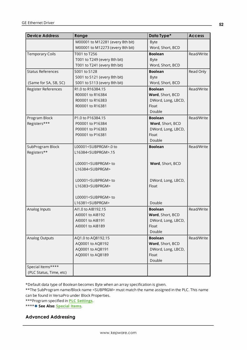
GE Ethernet Driver
Device Address Range Data Type* AccessM00001 to M12281 (every 8th bit)M00001 to M12273 (every 8th bit)
ByteWord, Short, BCD
Temporary Coils T001 to T256T001 to T249 (every 8th bit)T001 to T241 (every 8th bit)
BooleanByteWord, Short, BCD
Read/Write
Status References
(Same for SA, SB, SC)
S001 to S128S001 to S121 (every 8th bit)S001 to S113 (every 8th bit)
BooleanByteWord, Short, BCD
Read Only
Register References R1.0 to R16384.15R00001 to R16384R00001 to R16383R00001 to R16381
BooleanWord, Short, BCDDWord, Long, LBCD,FloatDouble
Read/Write
Program BlockRegisters***
P1.0 to P16384.15P00001 to P16384P00001 to P16383P00001 to P16381
BooleanWord, Short, BCDDWord, Long, LBCD,FloatDouble
Read/Write
SubProgram BlockRegisters**
L00001<SUBPRGM>.0 toL16384<SUBPRGM>.15
L00001<SUBPRGM> toL16384<SUBPRGM>
L00001<SUBPRGM> toL16383<SUBPRGM>
L00001<SUBPRGM> toL16381<SUBPRGM>
Boolean
Word, Short, BCD
DWord, Long, LBCD,Float
Double
Read/Write
Analog Inputs AI1.0 to AI8192.15AI0001 to AI8192AI0001 to AI8191AI0001 to AI8189
BooleanWord, Short, BCDDWord, Long, LBCD,FloatDouble
Read/Write
Analog Outputs AQ1.0 to AQ8192.15AQ0001 to AQ8192AQ0001 to AQ8191AQ0001 to AQ8189
BooleanWord, Short, BCDDWord, Long, LBCD,FloatDouble
Read/Write
Special Items****(PLC Status, Time, etc)
*Default data type of Boolean becomes Byte when an array specification is given.**The SubProgram name/Block name <SUBPRGM> must match the name assigned in the PLC. This namecan be found in VersaPro under Block Properties.***Program specified in PLC Settings.****Ã See Also: Special Items.
Advanced Addressing
www.kepware.com
52

GE Ethernet Driver
Bit Access to RegistersDefault Data Type OverrideString Access to RegistersArray Support
GE OPEN AddressingThe GE OPEN model selection has been provided to supply support for any GE SRTP compatible device thatis not currently listed in the standardmodel selectionmenu. The ranges of data for each data type havebeen expanded to allow a wide range of GE PLCs to be addressed. Although the address ranges shown heremay exceed the specific PLC's capability, the driver will respect all messages from the PLC regardingmemory range limits.
à Note: The default data types for dynamic tags are shown in bold.
Device Address Range Data Type* AccessDiscrete Inputs I0001 to I32768
I0001 to I32761 (every 8th bit)I0001 to I32753 (every 8th bit)
BooleanByteWord, Short, BCD
Read/Write
Discrete Outputs Q00001 to Q32768Q00001 to Q32761 (every 8th bit)Q00001 to Q32753 (every 8th bit)
BooleanByteWord, Short, BCD
Read/Write
Discrete Globals G00001 to G32768G00001 to G32761 (every 8th bit)G00001 to G32753 (every 8th bit)
BooleanByteWord, Short, BCD
Read/Write
Internal Coils M00001 to M32768M00001 to M32761 (every 8th bit)M00001 to M32753 (every 8th bit)
BooleanByteWord, Short, BCD
Read/Write
Temporary Coils T00001 to T32768T00001 to T32761 (every 8th bit)T00001 to T32753 (every 8th bit)
BooleanByteWord, Short, BCD
Read/Write
Status References
(Same for SA, SB, SC)
S00001 to S32768S00001 to S32761 (every 8th bit)S00001 to S32753 (every 8th bit)
BooleanByteWord, Short, BCD
Read Only
Register References R1.0 to R32768.15R00001 to R32768R00001 to R32767R00001 to R32765
BooleanWord, Short, BCDDWord, Long, LBCD,FloatDouble
Read/Write
Program BlockRegisters***
P00001 to P32768P00001 to P32767P00001 to P32765
Word, Short, BCDDWord, Long, LBCD,FloatDouble
Read/Write
SubProgram BlockRegisters**
L00001<SUBPRGM>.0 toL32768<SUBPRGM>.15
L00001<SUBPRGM> toL32768<SUBPRGM>
Boolean
Word, Short, BCD
Read/Write
www.kepware.com
53

GE Ethernet Driver
Device Address Range Data Type* AccessL00001<SUBPRGM> toL32767<SUBPRGM>
L00001<SUBPRGM> toL32765<SUBPRGM>
DWord, Long, LBCD,Float
Double
Analog Inputs AI1.0 to AI32768.15AI00001 to AI32768AI00001 to AI32767AI00001 to AI32765
BooleanWord, Short, BCDDWord, Long, LBCD,FloatDouble
Read/Write
Analog Outputs AQ1.0 to AQ32768.15AQ00001 to AQ32768AQ00001 to AQ32767AQ00001 to AQ32765
BooleanWord, Short, BCDDWord, Long, LBCD,FloatDouble
Read/Write
Special Items****(PLC Status, Time, etc)
Bulk Memory W1.0 to W65536.15W00001 to W65536W00001 to W65535W00001 to W65533
BooleanWord, Short, BCDDWord, Long, LBCD,FloatDouble
Read/Write
*Default data type of Boolean becomes Byte when an array specification is given.**The SubProgram name/Block name <SUBPRGM> must match the name assigned in the PLC. This namecan be found in VersaPro under Block Properties.***Program specified in PLC Settings.****See Also: Special Items.
Advanced AddressingBit Access to RegistersDefault Data Type OverrideString Access to RegistersArray Support
Horner OCS AddressingThe Horner OCS model selection has been provided to supply support for Horner Operator Control Stations.The ranges of data for each data type have been expanded to allow a wide range of Horner OCS devices tobe addressed. Although the address ranges shown here may exceed the specific device's capability, thedriver will respect all messages from the OCS regarding memory range limits.
à Note: The default data types for dynamic tags are bold.
Device Address Range Data Type* AccessDiscrete Inputs I0001 to I2048
I0001 to I2041 (every 8th bit)I0001 to I2033 (every 8th bit)
BooleanByteWord, Short, BCD
Read/Write
www.kepware.com
54
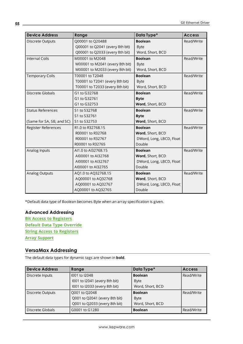
GE Ethernet Driver
Device Address Range Data Type* AccessDiscrete Outputs Q00001 to Q20488
Q00001 to Q2041 (every 8th bit)Q00001 to Q2033 (every 8th bit)
BooleanByteWord, Short, BCD
Read/Write
Internal Coils M00001 to M2048M00001 to M2041 (every 8th bit)M00001 to M2033 (every 8th bit)
BooleanByteWord, Short, BCD
Read/Write
Temporary Coils T00001 to T2048T00001 to T2041 (every 8th bit)T00001 to T2033 (every 8th bit)
BooleanByteWord, Short, BCD
Read/Write
Discrete Globals G1 to G32768G1 to G32761G1 to G32753
BooleanByteWord, Short, BCD
Read/Write
Status References
(Same for SA, SB, and SC)
S1 to S32768S1 to S32761S1 to S32753
BooleanByteWord, Short, BCD
Read/Write
Register References R1.0 to R32768.15R00001 to R32768R00001 to R32767R00001 to R32765
BooleanWord, Short, BCDDWord, Long, LBCD, FloatDouble
Read/Write
Analog Inputs AI1.0 to AI32768.15AI00001 to AI32768AI00001 to AI32767AI00001 to AI32765
BooleanWord, Short, BCDDWord, Long, LBCD, FloatDouble
Read/Write
Analog Outputs AQ1.0 to AQ32768.15AQ00001 to AQ32768AQ00001 to AQ32767AQ00001 to AQ32765
BooleanWord, Short, BCDDWord, Long, LBCD, FloatDouble
Read/Write
*Default data type of Boolean becomes Byte when an array specification is given.
Advanced AddressingBit Access to RegistersDefault Data Type OverrideString Access to RegistersArray Support
VersaMax AddressingThe default data types for dynamic tags are shown in bold.
Device Address Range Data Type* AccessDiscrete Inputs I001 to I2048
I001 to I2041 (every 8th bit)I001 to I2033 (every 8th bit)
BooleanByteWord, Short, BCD
Read/Write
Discrete Outputs Q001 to Q2048Q001 to Q2041 (every 8th bit)Q001 to Q2033 (every 8th bit)
BooleanByteWord, Short, BCD
Read/Write
Discrete Globals G0001 to G1280 Boolean Read/Write
www.kepware.com
55
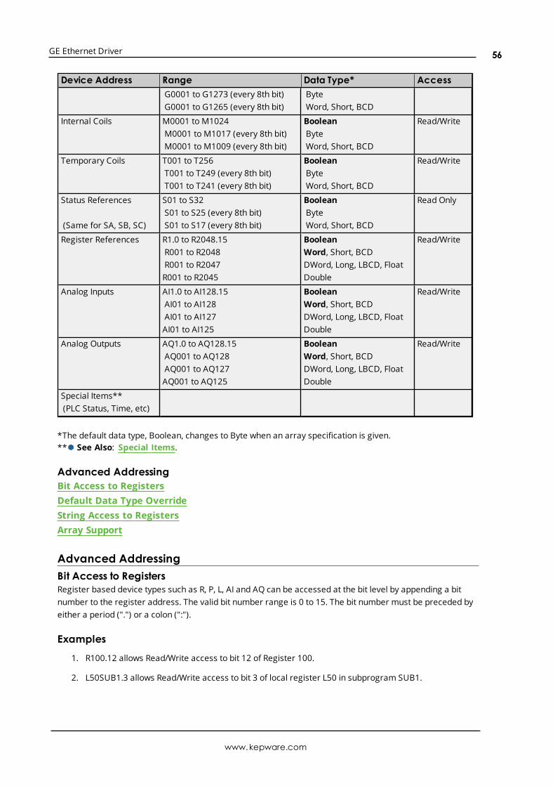
GE Ethernet Driver
Device Address Range Data Type* AccessG0001 to G1273 (every 8th bit)G0001 to G1265 (every 8th bit)
ByteWord, Short, BCD
Internal Coils M0001 to M1024M0001 to M1017 (every 8th bit)M0001 to M1009 (every 8th bit)
BooleanByteWord, Short, BCD
Read/Write
Temporary Coils T001 to T256T001 to T249 (every 8th bit)T001 to T241 (every 8th bit)
BooleanByteWord, Short, BCD
Read/Write
Status References
(Same for SA, SB, SC)
S01 to S32S01 to S25 (every 8th bit)S01 to S17 (every 8th bit)
BooleanByteWord, Short, BCD
Read Only
Register References R1.0 to R2048.15R001 to R2048R001 to R2047R001 to R2045
BooleanWord, Short, BCDDWord, Long, LBCD, FloatDouble
Read/Write
Analog Inputs AI1.0 to AI128.15AI01 to AI128AI01 to AI127AI01 to AI125
BooleanWord, Short, BCDDWord, Long, LBCD, FloatDouble
Read/Write
Analog Outputs AQ1.0 to AQ128.15AQ001 to AQ128AQ001 to AQ127AQ001 to AQ125
BooleanWord, Short, BCDDWord, Long, LBCD, FloatDouble
Read/Write
Special Items**(PLC Status, Time, etc)
*The default data type, Boolean, changes to Byte when an array specification is given.**Ã See Also: Special Items.
Advanced AddressingBit Access to RegistersDefault Data Type OverrideString Access to RegistersArray Support
Advanced AddressingBit Access to RegistersRegister based device types such as R, P, L, AI and AQ can be accessed at the bit level by appending a bitnumber to the register address. The valid bit number range is 0 to 15. The bit number must be preceded byeither a period (".") or a colon (":").
Examples
1. R100.12 allows Read/Write access to bit 12 of Register 100.
2. L50SUB1.3 allows Read/Write access to bit 3 of local register L50 in subprogram SUB1.
www.kepware.com
56

GE Ethernet Driver
à Note: All device addresses can be prefixed with a % sign if needed, such as %R100. This can aid inconverting from other OPC servers or communications drivers.
Default Data Type OverrideThe default data types for each device type are shown in PACSystems Addressing. The defaults can beoverridden by appending data type indicators to the device address. The possible data type indicators are asfollows.
Indicators Data TypeF Float
S Short
L Long
M String
(BCD) BCD
ExamplesAddress DescriptionR100 F Access R100 as a floating point value
R300 L Access R300 as a long
R400–R410 M Access R400-R410 as a string with a length of 22 bytes.(LoHi byte order is assumed.)
P100 S Access P100 as a short
L200SUB1-L210SUB1 M
Access L200-L210 in subprogram SUB1 as a string with a length of 22 bytes. (LoHibyte order is assumed.)
à Note: There must be a space between the register number and the data type indicator.
String Access to RegistersRegister space can be accessed as string data by appending the "M" data indicator. The length of the stringis based on how the device address reference is entered. Each register addressed can contain twocharacters. The byte order of characters in registers can be specified by appending an optional "H" for HiLoor "L" for LoHi after the "M" data indicator. If no byte order is specified, LoHi order is assumed.
ExamplesAddress DescriptionR100-R200 M Access Register R100 as string with a length of 202 bytes. (LoHi byte order is
assumed.)
R400 M Access Register R400 as a string with a length of 4 bytes. (LoHi byte order isassumed.)
R405-R405 M Access Register R405 as a string with a length of 2 bytes. (LoHi byte order isassumed.)
L100SUB1-L100SUB1 M
Access local register L100 in subprogram SUB1 as a string with a length of 2 bytes.(LoHi byte order is assumed.)
R100-R200 M H Access Register R100 as string with a length of 202 bytes. HiLo byte order is explicitlyspecified.
R100-R200 M L Access Register R100 as string with a length of 202 bytes. LoHi byte order is explicitlyspecified.
www.kepware.com
57

GE Ethernet Driver
à Notes: The maximum string length is 255 bytes. For HiLo byte ordering, the string "AB" would be stored ina register as 0x4142. For LoHi byte ordering, the string "AB" would be stored in a register as 0x4241. Theremust be a space between the "M" data type indicator and the byte order indicator.
Array SupportAn array is a collection of contiguous elements of a given data type. Arrays are supported by the followingdata types: byte, word, short, DWord, long, float and char. The maximum array size is determined by the"Maximum Bytes Per Request" property in Device Properties. If it is set at its maximum value, arrays can bespecified up to 1024 elements for 16 bit data types and 512 elements for 32 bit data types. For moreinformation, refer toMaximum Bytes Per Request.
Maximum Array Size forReferencedor Mapped Variables
512 DWords (longs, floats), 1024 words (shorts) or 2048 bytes andchars for a total of 16384 bits
Maximum Array Size forSymbolic Variables
512 DWords (longs, floats), 1024 words (shorts) or 1024 bytes andchars for a total of 16384 bits
à Note: The number of usable bytes is directly reflective of the block size.
ExamplesAddress Address BreakdownG1 [4] includes the following byte addresses
à Note:G25 indicates the fourth byte beginning atbit 25.
G1, G9, G17, G251 row implied = 4 bytes4 x 8 (byte) = 32 total bits
R16 [3][4] includes the following Word addresses: R16, R17, R18, R19, R20, R21, R22, R23, R24, R25,R26, R273 rows x 4 columns = 12 words12 x 16 (word) = 192 total bits
P10 [5] includes the following Word addresses: P10, P11, P12, P13, P141 rows x 5 columns = 5 words5 x 16 (word) = 80 total bits
Special ItemsThough not visible in the server configuration, dynamic tags with these addresses are automatically createdand can be browsed by the OPC client. They will be found under the <Channel Name>.<Device Name>._InternalTags group. If the OPC client does not support browsing or a non-OPC client is being used, users cancreate their own static and dynamic tags using these addresses. The default data types for dynamic tags areshown in bold.
DeviceAddress Range Data
Type Access
_OVERSWEEP Oversweep flag. This is meaningful only when constant sweepmodeis active.
1 = Constant Sweep value exceeded0 = No oversweep condition exists
Boolean ReadOnly
_CONSWEEP Constant sweepmode. Boolean ReadOnly
www.kepware.com
58

GE Ethernet Driver
DeviceAddress Range Data
Type Access
1 = Constant SweepMode active0 = Constant SweepMode not active
_NEWFT PLC Fault entry since last read.
1 = PLC Fault Table has changed since last read by the server0 = PLC Fault Table is unchanged since last read by the server
Boolean ReadOnly
_NEWIOFT IO Fault entry since last read.
1 = IO Fault Table has changed since last read by the server0 = IO Fault Table is unchanged since last read by the server
Boolean ReadOnly
_FTSTATUS PLC Fault entry present
1 = One or more fault entries in PLC Fault Table0 = PLC Fault table is empty
Boolean ReadOnly
_IOSTATUS IO Fault entry present
1 = One or more fault entries in IO Fault Table0 = IO Fault Table is empty
Boolean ReadOnly
_PROGATTACH
Programmer attachment in system flag.
1 = Programmer attachment found in system0 = No programmer attachment found in system
Boolean ReadOnly
_ENSWITCH Front panel ENABLED/DISABLED switch setting.
1 = Outputs disabled0 = Outputs enabled
Boolean ReadOnly
_RUN Front panel RUN/STOP switch setting.
1 = Run0 = Stop
_OEMPROT OEM protected bit.
1 = OEM protection in effect0 = No OEM protection
Boolean ReadOnly
_SPRGCHG Program changed flag.
1 = Program changed0 = No program change(90-70 release 2.x and later)
Boolean ReadOnly
_STATE Current PLC State
0 = Run I/O enabled1 = Run I/O disabled2 = Stop I/O disabled3 = CPU stop faulted4 = CPU halted5 = CPU suspended
Byte,Char
ReadOnly
www.kepware.com
59

GE Ethernet Driver
DeviceAddress Range Data
Type Access
6 = Stop I/O enabled
_PROGNUM Control program number SRTP Master is currently logged into.
-1 = SRTP Master is not logged into a task0 = SRTP Master is logged into task 0
Byte,Char
ReadOnly
_PRIVLEVEL Current privilege level of server for accessing memory in PLC CPU(0-4)
Byte,Char
ReadOnly
_SWEEPTIME Time taken by the last complete sweep for the main controlprogram task.
The value returned is a whole number representing the number oftenths of a millisecond. The Sweep Time in milliseconds is 1/10 ofthis value. For example, if _SWEEPTIME is 123, the actual SweepTime is 12.3 milliseconds.
Word,Short
ReadOnly
_SNPID CPU Controller ID. String ReadOnly
_PROGNAME Name of control program task in the PLC CPU. String ReadOnly
_SNUM_PROGS
Number of control program tasks defined for the PLC CPU. Byte,Char
ReadOnly
_SPROG_FLAGS
Bit flags indicating which control programs tasks haveprogrammers attached. Bit 0 = control program 1.
Byte,Char
ReadOnly
_TIME Internal time and date of the PLC CPU. Format:
SSMMHHDDMoYYDwwhere
SS = Seconds (0-59)MM == Minutes (0-59)HH = Hours (0-23)DD = Day (1- 31)Mo = Month (1-12)YY = Year (0-99)Wd = Day of week (1-Sunday, 2-Monday, etc)
String ReadOnly
_SECOND PLC Time: Seconds (0-59) Byte,Char
ReadOnly
_MINUTE PLC Time: Minutes (0-59) Byte,Char
ReadOnly
_HOUR PLC Time: Hours (0-23) Byte,Char
ReadOnly
_DAY PLC Date: Day (1- 31) Byte,Char
ReadOnly
_MONTH PLC Date: Month (1-12) Byte,Char
ReadOnly
_YEAR PLC Date: Year (0-99) Byte,Char
ReadOnly
_DOW PLC Date: Day of week (1-Sunday, 2-Monday, etc) Byte, Read
www.kepware.com
60

GE Ethernet Driver
DeviceAddress Range Data
Type Access
Char Only
www.kepware.com
61
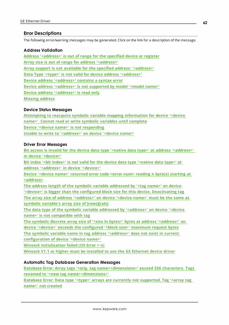
GE Ethernet Driver
Error DescriptionsThe following error/warning messages may be generated. Click on the link for a description of the message.
Address ValidationAddress '<address>' is out of range for the specified device or registerArray size is out of range for address '<address>'Array support is not available for the specified address: '<address>'Data Type '<type>' is not valid for device address '<address>'Device address '<address>' contains a syntax errorDevice address '<address>' is not supported by model '<model name>'Device address '<address>' is read onlyMissing address
Device Status MessagesAttempting to reacquire symbolic variable mapping information for device '<devicename>'. Cannot read or write symbolic variables until completeDevice '<device name>' is not respondingUnable to write to '<address>' on device '<device name>'
Driver Error MessagesBit access is invalid for the device data type '<native data type>' at address '<address>'in device '<device>'Bit index '<bit index>' is not valid for the device data type '<native data type>' ataddress '<address>' in device '<device>'Device '<device name>' returned error code <error num> reading n byte(s) starting at<address>The address length of the symbolic variable addressed by '<tag name>' on device'<device>' is bigger than the configured block size for this device. Deactivating tagThe array size of address '<address>' on device '<device name>' must be the same assymbolic variable's array size of [rows][cols]The data type of the symbolic variable addressed by '<address>' on device '<devicename>' is not compatible with tagThe symbolic discrete array size of '<size in bytes>' bytes at address '<address>' ondevice '<device>' exceeds the configured '<block size>' maximum request bytesThe symbolic variable name in tag address '<address>' does not exist in currentconfiguration of device '<device name>'Winsock initialization failed (OS Error = n)Winsock V1.1 or higher must be installed to use the GE Ethernet device driver
Automatic Tag Database Generation MessagesDatabase Error: Array tags '<orig. tag name><dimensions>' exceed 256 characters. Tagsrenamed to '<new tag name><dimensions>'Database Error: Data type '<type>' arrays are currently not supported. Tag '<array tagname>' not created
www.kepware.com
62

GE Ethernet Driver
Database Error: Data type '<type>' for tag '<tag name>' is currently not supported. Tagnot createdDatabase Error: Data type '<type>' for tag '<tag name>' not found in import file. Settingto defaultDatabase Error: Logic Developer Variable Arrays are currently not supported. Array Tag(s) '<array tag name>' not createdDatabase Error: No Reference Address found for tag '<tag name>' in import file. Tag notcreatedDatabase Error: Only variables with Data Source '<data source name>' are imported.Data Source '<data source name>' is not supported. Tag '<tag name>' not createdDatabase Error: Tag '<orig. tag name>' exceeds 256 characters. Tag renamed to '<newtag name>'Unable to generate a tag database for device <device name>. Reason: Import file isinvalid or corruptUnable to generate a tag database for device <device name>. Reason: Low memoryresources
Address '<address>' is out of range for the specified device or registerError Type:Warning
Possible Cause:
1. A tag address that has been specified statically via DDE references a location that is beyond therange of supported locations for the device.
2. A tag address has been assigned a bit index that is out of range (greater than or equal to 32).
Solution:
1. Verify the address is correct; if it is not, re-enter it in the client application.
2. Remove the bit index syntax from the tag address or change it to one that is in range for the datatype.
Array size is out of range for address '<address>'Error Type:Warning
Possible Cause:
1. The number of elements in an array definition exceeds the range of elements supported by theaddress type.
2. The number of elements in an array definition exceeds the maximum number of data values thatmay be obtained from the device in a single request.
Solution:Reduce the number of referenced elements in the array definition.
www.kepware.com
63

GE Ethernet Driver
Array support is not available for the specified address: '<address>'Error Type:Warning
Possible Cause:A tag address that has been specified statically contains an array reference for an address type that doesn'tsupport arrays.
Solution:Re-enter the address in the client application to remove the array reference or correct the address type.
Data Type '<type>' is not valid for device address '<address>'Error Type:Warning
Possible Cause:A tag address that has been specified statically has been assigned an invalid data type.
Solution:Modify the requested data type in the client application.
Device address '<address>' contains a syntax errorError Type:Warning
Possible Cause:A tag address that has been specified statically contains one or more invalid characters.
Solution:Re-enter the address in the client application.
Device address '<address>' is not supported by model '<model name>'Error Type:Warning
Possible Cause:A tag address that has been specified statically references a location that is valid for the communicationsprotocol but not supported by the target device.
Solution:Verify that the address is correct; if it is not, re-enter it in the client application. Also verify that the selectedmodel name for the device is correct.
Device address '<address>' is Read OnlyError Type:Warning
Possible Cause:
www.kepware.com
64

GE Ethernet Driver
A tag address that has been specified statically has a requested access mode that is not compatible withwhat the device supports for that address.
Solution:Change the access mode in the client application.
Missing addressError Type:Warning
Possible Cause:A tag address that has been specified statically has no length.
Solution:Re-enter the address in the client application.
Attempting to reacquire symbolic variable mapping information for device'<device name>'. Cannot read or write symbolic variables until completeError Type:Warning
Possible Cause:A new configuration is being downloaded to the device or the configuration has been lost (possibly due topower failure).
Solution:The driver should automatically recover once a new device configuration has been restored.
Device '<device name>' not respondingError Type:Serious
Possible Cause:
1. The connection between the device and the Host PC is broken.
2. The IP address assigned to the device is incorrect.
3. The response from the device took longer to receive than the amount of time specified in the"Request Timeout" device setting.
Solution:
1. Verify the cabling between the PC and the PLC device.
2. Verify that the IP address given to the named device matches that of the actual device.
3. Increase the Request Timeout setting so that the entire response can be handled.
www.kepware.com
65

GE Ethernet Driver
Unable to write to '<address>' on device '<device name>'Error Type:Serious
Possible Cause:
1. The connection between the device and the Host PC is broken.
2. The named device may have been assigned an incorrect IP address.
Solution:
1. Verify the cabling between the PC and the PLC device.
2. Verify that the IP address given to the named device matches that of the actual device.
Bit access is invalid for the device data type '<native data type>' at address'<address>' in device '<device>'Error Type:Warning
Possible Cause:A tag address has been assigned a bit index that is invalid for its native data type.
Solution:Remove the bit index syntax from the tag address or modify the symbolic variable in the controller to one ofthe following native data types: Byte, Int, Uint, Word, Dint, or DWord.
Bit index '<bit index>' is not valid for the device data type '<native datatype>' at address '<address>' in device '<device>'Error Type:Warning
Possible Cause:A tag address has been assigned a bit index that is out of range for its native data type.
Solution:Correct the tag address's bit index to be within the native data type's range.
The native data type ranges are as follows:
l Byte: 0-7.
l Int, Uint, Word: 0-15.
l Dint and DWord: 0-31.
Device '<device name>' returned error code <error num> reading n byte(s)starting at <address>Error Type:Error
www.kepware.com
66
GE Ethernet Driver
Possible Cause:An attempt has beenmade to read a location that does not exist.
Solution:Review the address map for the device in question andmake necessary adjustments in the clientapplication.
The address length of the symbolic variable addressed by '<tag name>' ondevice '<device>' is bigger than the configured block size for this device.Deactivating tagError Type:Error
Possible Cause:The requested tag is larger than the configured block size for this device. This can be caused by the namebeing too big or requested packet being too big.
Solution:Increase the block size or change name size.
The array size of address '<address>' on device '<device name>' must be thesame as symbolic variable's array size of [rows][cols]Error Type:Warning
Possible Cause:The array dimensions given in the tag address, if any, are not the same as the array size of the referencedsymbolic variable.
Solution:Determine the array dimensions of the variable as currently defined in the device. Adjust the tag address tomatch.
The data type of the symbolic variable addressed by '<address>' on device'<device name>' is not compatible with tagError Type:Warning
Possible Cause:The native data type of the symbolic variable, as currently defined in the device, is not compatible with thedata type of the tag.
Solution:Adjust the data type of the tag to match the variable's native data type.
See Also:Symbolic Variables
www.kepware.com
67
GE Ethernet Driver
The symbolic discrete array size of '<size in bytes>' bytes at address'<address>' on device '<device>' exceeds the configured '<block size>'maximum request bytes.Error Type:Warning
Possible Cause:The number of bytes required to obtain a symbolic discrete array in a single request exceeds the maximumconfigured block size.
Solution:
1. Increase the Maximum Bytes Per Request property (located inDevice Properties |Communications Settings) to accommodate the actual size of the array.
2. If the symbolic discrete array is larger than 2048 bytes, reconfigure the controller to assign thesymbolic array to non-discrete memory. For example, a response containing a symbolic non-discreteDWord array of 64 elements contains 256 bytes (64 elements * 4 bytes per DWord).
3. Separate the array into smaller arrays in order to reduce the number of referenced elements in eacharray definition.
4. Read the individual array elements in separate requests (instead of reading the array itself).
Notes:
1. Symbolic variables assigned to discrete memory consume one byte per bit. For example, a bytevariable actually requires eight bytes to obtain the data for each bit. Therefore, a responsecontaining a symbolic discrete DWord array of 64 elements contains 2048 bytes (64 elements * 4bytes per DWord * 8 bytes per byte).
2. For more information, refer to "Importing Array Elements (Index)" in Proficy Logic Developer ArrayTag Import.
See Also:Communications Settings
The symbolic variable name in tag address '<address>' does not exist incurrent configuration of device '<device name>'.Error Type:Warning
Possible Cause:The named variable does not exist in the current device configuration.
Solution:
1. Verify that variable is defined in current device configuration.
2. Check the spelling of the variable name.
www.kepware.com
68

GE Ethernet Driver
à Note: To optimize driver performance, it is recommended that all tags with invalid symbolic variableaddresses be removed from the server configuration or not be used by a client application.
Winsock initialization failed (OS Error = n)Error Type:Fatal
OSError: Indication Possible Solution
10091 Indicates that the underlying network subsystem isnot ready for network communication.
Wait a few seconds and restart the driver.
10067 Limit on the number of tasks supported by theWindows Sockets implementation has beenreached.
Close one or more applications that maybe using Winsock and restart the driver.
Winsock V1.1 or higher must be installed to use the GE Ethernet device driverError Type:Fatal
Possible Cause:The version number of the Winsock DLL found on the system is less than 1.1.
Solution:Upgrade Winsock to version 1.1 or higher.
Database Error: Array tags [orig. tag name] [dimensions] exceed 256characters. Tags renamed to [new tag name] [dimensions]Error Type:Warning
Possible Cause:The name assigned to an array tag originates from the variable name in the import file. This name exceedsthe 256-character limitation and will be renamed to one that is valid. [Dimensions] define the number ofdimensions for the given array tag. XXX for 1 Dimension, XXX_YYY for 2 Dimensions. The number of X's andY's approximates the number of elements for the respective dimensions. Since such an error will occur foreach element, generalizing with XXX and YYY implies all array elements will be affected.
Solution:None.
See Also:Import File-to-Server Name Conversions
Database Error: Data type '<type>' arrays are currently not supported. Tag'<array tag name>' not createdError Type:Warning
www.kepware.com
69

GE Ethernet Driver
Possible Cause:Boolean or String array tags of 1 or 2 dimensions are not supported at this time.
Solution:For Boolean array tags, individual array elements of the tag if specified in the import file will be generated.Furthermore, the driver will also automatically create individual elements for the array tag (except for bitwithin word type Boolean array tags).
à Note: For String array tags, neither the array tag or the individual elements will be generated. String datatype is currently not supported by the driver. Thus, avoid using String data type if possible.
Database Error: Data type '<type>' for tag '<tag name>' is currently notsupported. Tag not created.Error Type:Warning
Possible Cause:The data type <type> as specified in the import file cannot be resolved or isn't natively supported by thedriver. The tag was not automatically generated.
Solution:For applicable tags, avoid using data type <type> in the VersaPro/Logic Developer projects.
Database Error: Data type '<type>' for tag '<tag name>' not found in importfile. Setting to default.Error Type:Warning
Possible Cause:The definition of data type '<type>', for tag <tag name>, could not be found in the import file.
Solution:This tag will take on the default type for the given address type as assigned by the driver.
Database Error: Logic Developer Variable Arrays are currently not supported.Array Tag(s) '<array tag name>' not createdError Type:Warning
Possible Cause:Array tags of 1 or 2 dimensions originating from a Logic Developer import file are not supported at this time.The array tags were not automatically generated.
Solution:For applicable tags, avoid using arrays in the Logic Developer projects.
www.kepware.com
70

GE Ethernet Driver
Database Error: No Reference Address found for tag '<tag name>' in importfile. Tag not createdError Type:Warning
Possible Cause:Variables without a reference address cannot have a tag created since the reference address determinesthe tag's address. The tag was not automatically generated.
Solution:Verify the <tag name> has a PLC as a data source and that reference address (PLC memory location) hasbeen assigned to it.
Database Error: Only variables with Data Source '<data source name>' areimported. Data Source '<data source name>' is not supported. Tag '<tagname>' not createdError Type:Warning
Possible Cause:In Logic Developer, variables can take on a data value from a number of sources. For use in the OPC server,the source must be a GE Ethernet PLC. The tag was not automatically generated.
Solution:Verify the <tag name> has a PLC as a data source.
Database Error: Tag '<orig. tag name>' exceeds 256 characters. Tag renamedto '<new tag name>'Error Type:Warning
Possible Cause:The name assigned to a tag originates from the variable name in the import file. This name exceeds the 256character limitation and will be renamed to one that is valid.
Solution:None.
See Also:Import File-to-Server Name Conversions
Unable to generate a tag database for device <device name>. Reason:Import file is invalid or corruptError Type:Warning
Possible Cause:
www.kepware.com
71

GE Ethernet Driver
The file specified as the Tag Import File (in the Variable Import Settings property group) is a corrupt importfile (*.snf or*.csv) or improperly formatted Logic Developer text file.
Solution:Select a valid, properly formatted VersaPro/Logic Developer variable import file or retry the tag exportprocess in the respective application to produce a new import file.
See Also:Automatic Tag Database Generation
Unable to generate a tag database for device <device name>. Reason: Lowmemory resourcesError Type:Warning
Possible Cause:Memory required for database generation could not be allocated. The process is aborted.
Solution:Close any unused applications and/or increase the amount of virtual memory. Then, try again.
www.kepware.com
72

GE Ethernet Driver
Index
3
311 Addressing 38
313 Addressing 39
331 Addressing 40
341 Addressing 41
350 Addressing 42
360 Addressing 43
7
731 Addressing 44
732 Addressing 46
771 Addressing 47
772 Addressing 48
781 Addressing 50
782 Addressing 51
A
Address '<address>' is out of range for the specified device or register 63
Address Descriptions 33
Advanced Addressing 56
Advanced Channel Properties 8
Allow Sub Groups 15
Array size is out of range for address '<address>' 63
Array support is not available for the specified address: '<address>' 64
Attempting to reacquire symbolic variable mapping information for device '<device name>'. Cannot reador write symbolic variables until complete 65
Automatic Tag Database Generation 17
B
BCD 32
Bit access is invalid for the device data type '<native data type>' at address '<address>' in device'<device>' 66
Bit index '<bit index>' is not valid for the device data type '<native data type>' at address '<address>' in
www.kepware.com
73
GE Ethernet Driver
device '<device>' 66
Boolean 32
Byte 32
C
Channel Assignment 10
Channel Properties 6
Channel Properties - Ethernet Communications 7
Channel Properties - General 6
Channel Properties - Write Optimizations 7
Cimplicity Logic Developer Array Tag Import 25
Cimplicity Logic Developer Import Preparation: Logic Developer Steps 23
Cimplicity Logic Developer Import Preparation: OPC Server Steps 25
Communications Settings 15
Communications Timeouts 12-13
Connect Timeout 12
Create 15
D
Data Collection 11
Data Type '<type>' is not valid for device address '<address>' 64
Data Types Description 32
Database Error
Data type '<type>' arrays are currently not supported. Tag '<array tag name>' not created 69
Database Error: Array tags [orig. tag name] [dimensions] exceed 256 characters. Tags renamed to [newtag name] [dimensions] 69
Database Error: Data type '<type>' for tag '<tag name>' is currently not supported. Tag not created 70
Database Error: Data type '<type>' for tag '<tag name>' not found in import file. Setting to Default Type'<type>' 70
Database Error: Logic Developer Variable Arrays are currently not supported. Array Tag(s) '<array tagname>' not created 70
Database Error: No Reference Address found for tag '<tag name>' in import file. Tag not created 71
Database Error: Only variables with Data Source '<data source name>' are imported. Data Source '<datasoure name>' is not.. 71
Database Error: Tag '<orig. tag name>' exceeds 256 characters. Tag renamed to '<new tag name>' 71
Delete 15
Demote on Failure 13
Demotion Period 13
www.kepware.com
74
GE Ethernet Driver
Description 10
device 62
Device '<device name>' returned error code <error num> reading in byte(s) starting at <address> 66
Device '<device name> not responding 65
Device address '<address>' contains a syntax error 64
Device address '<address>' is not supported by model '<model name>' 64
Device address '<address>' is Read Only 64
Device Properties 9
Device Properties - Auto-Demotion 13
Device Properties - General 9
Device Properties - Tag Generation 13
Diagnostics 7
Discard Requests when Demoted 13
Do Not Scan, Demand Poll Only 12
Driver 7, 10
Duty Cycle 8
DWord 32
E
Error Descriptions 62
F
Float 32
G
GE OPEN Addressing 53
Generate 14
H
Highlighting LogicDeveloper Variables 25
Highlighting Proficy Logic Developer Variables 28
Highlighting VersaPro Variables 21
Horner OCS Addressing 54
www.kepware.com
75

GE Ethernet Driver
I
ID 10
IEEE-754 floating point 9
Import File-to-Server Name Conversions 18
Importing LogicDeveloper Tags 23
Importing Proficy Logic Developer Tags 25
Importing VersaPro Tags 19
Initial Updates from Cache 12
Inter-Request Delay 13
L
LBCD 32
Long 32
M
Missing address 65
Model 10
N
Name 10
Network Adapter 7
Non-Normalized Float Handling 9
O
On Device Startup 14
On Duplicate Tag 14
Optimization Method 8
Optimizing GE Ethernet Communications 30
Overview 5
Overwrite 15
www.kepware.com
76

GE Ethernet Driver
P
PACSystems Addressing 33
Parent Group 15
PLC Settings 16
Proficy Logic Developer Array Tag Import 29
Proficy Logic Developer Import Preparation: Logic Developer Steps 26
Proficy Logic Developer Import Preparation: OPC Server Steps 28
protocol 6
R
Redundancy 16
Request All Data at Scan Rate 11
Request Data No Faster than Scan Rate 11
Request Timeout 12
Respect Client-Specified Scan Rate 11
Respect Tag-Specified Scan Rate 12
Retry Attempts 12
S
ScanMode 11
Setup 6
Short 32
Simulated 11
Special Items 58
Symbolic Variables 35
T
Tag Generation 13
Tag Hierarchy 17
The address length of the symbolic variable addressed by '<tag name>' on device '<device>' is bigger 67
The array size of address '<address>' on device '<device name>' must be the same as symbolicvariable's array size of [rows][cols] 67
The data type of the symbolic variable addressed by '<address>' on device '<device name>' is notcompatible with tag 67
www.kepware.com
77
GE Ethernet Driver
The symbolic discrete array size of '<size in bytes>' bytes at address '<address>' on device '<device>'exceeds the configured '<block size>' maximum request bytes 68
The symbolic variable name in tag address '<address>' does not exist in current configuration of device'<device name>' 68
Timeouts to Demote 13
U
Unable to generate a tag database for device <device name>. Reason 71
Unable to generate a tag database for device <device name>. Reason: Import file is invalid or corrupt 71
Unable to generate a tag database for device <device name>. Reason: Lowmemory resources 72
Unable to write tag '<address>' on device '<device name>' 66
V
Variable Import Settings 16
VersaMax Addressing 55
VersaPro Array Tag Import 22
VersaPro Import Preparation: VersaPro Steps 19
VersaPro Import Preparation: OPC Server Steps 21
W
Winsock initialization failed (OS Error = n) 69
Winsock V1.1 or higher must be installed to use the GE Ethernet device driver 69
Word 32
Write All Values for All Tags 8
Write Only Latest Value for All Tags 8
Write Only Latest Value for Non-Boolean Tags 8
Write Optimizations 8
www.kepware.com
78