ge 360104
DESCRIPTION
Ge 360102TRANSCRIPT

BLIGHT, G. E. (1986). Gkmxhnique 36, No. 1,13346
Pressures exerted by materials stored part I, coarse materials
G. E. BLIGHT*
Silos are usually designed on the basis of simple theory which is used to predict horizontal pressures on the walls. The pressures generated depend on many factors, including the pattern of flow within the contained material, the method of operating the silo and also the mechanical characteristics of the material. This Paper compares pressures measured in a number of full-scale silos containing coarse materials with the predictions of commonly accepted design theory. It shows that, although the silo arching theory gives an acceptable estimate of the average pressure on a silo wall, it does not always provide an adequate design envelope. It is preferable to use a simple straight line variation of pressures with depth for design.
Les silos sont generalement calcult sur la base d’une theorie tres simple utilisee pour prevoir les pressions horizontales sur les mum. Les pressions reellement exer- &es dependent de plusieurs facteurs, dont la forme de l’ecoulement a l’interieur de la mat&e, le principe du fonctionement du silo et aussi les caracteristiques mtca- niques de la mat&e ensilee. L’article compare les press- ions mesurees dans quelques grands silos contenant des matieres a gros grains avec les previsions de la theorie classique. Bien que la thtorie de I’effet de votite dans un silo donne une evaluation acceptable de la pression moyenne sur la paroi mm, cette theorie ne fournit pas toujours une enveloppe acceptable. II parait preferable d’utiliser pour les calculs des pressions proportionelles a la profondeur.
KEYWORDS: case history; design; earth pressures; field instrumentation; granular materials; silos.
INTRODUCTION Storage silos form a class of structure that is subject to an unusually high rate of structural and functional failure. The extent of structural failure varies from cracking of the walls of rein- forced concrete silos to localized denting or buck- ling of the walls of steel silos and to complete splitting or collapse of the walls. Functional failure may be represented by the inability to extract the contents of the silo, spoiling of the contents by leakage of rain-water through cracks in the walls, excessive vibration leading to crack- ing and a variety of similar shortcomings. Foun- dation problems may also result in either
Discussion on this Paper closes on 1 July 1986. For further details see inside back cover. * University of the Witwatersrand.
in silos :
functional or structural problems arising from dif- ferential settlement or, in several recorded instances, in toppling of the structure.
Theimer (1969) described failure by toppling or partial or complete collapse experienced by 14 reinforced concrete grain silo complexes and records less spectacular, but equally serious, problems that arose in eight other cases. Sadler (1980) described 15 cases of partial or complete collapse of silos built in the US to store materials as diverse as raw or washed coal, polyethylene pellets, grain, silage and coke.
An extensive inventory of failures in steel, rein- forced brickwork and reinforced concrete silos in Europe has also been given by Ravenet (1981).
The denting of steel silos has been described by Jenike (1967). In a recent survey of grain storage silos in Scandinavia (Wigram, 1980), 34% of the reinforced concrete silos examined were found to have suffered vertical cracking of the walls.
Most functional failures of silos arise because they will not empty or because they empty in an unforeseen way. Functional failure may lead to structural failure. For example, Sadler (1980) described how emptying of a steel silage silo caused a void to form at the base of the silo while the material above arched across the void. As a result of the increased axial load in the walls, the walls buckled and the silo collapsed.
The frequent and continuing problems experi- enced with silos of all types may be ascribed to the following: silos are one of the few classes of structure that are subjected to their full or more than full design load over most of their life-span; the estimation of loads and pressures is uncertain because
(a) pressures are dependent on the flow pattern that develops in the silo, which may be diffi- cult to determine at the design stage, or may not be appreciated by the designer: the flow pattern may also be affected by the way in which a silo is operated
(b) pressures depend on the characteristics of the stored material: very often, silos have to be designed before the material they are to store is available or has been produced; conse- quently, the design must be based on assumed
33

34 BLIGH-I
(4
(4
(4
rather than measured material properties; also, the properties of stored materials may (and probably will) vary to an unpredictable extent during the operating life of the silo relatively slight deviations during construc- tion from the designed form and dimensions of a silo may have unexpectedly large effects on the pressures (Jenike, 1980; Nielsen & Kristiansen, 1980), e.g. a localized internal ridge may cause a substantial pressure increase at that point slight variations in material properties, mois- ture content, storage time, etc. may result in the formation of arches in a silo: it is imposs- ible to predict the positions at which arches will form and almost impossible to predict the pressure concentrations that will result from the arch action, and most importantly it is uneconomic to design a silo to resist either the arching pressures or the shock loading that may result when an arch collapses the accuracy of theories from which silo press- ures can be calculated is limited by the assumptions on which they are based: the situations to which the theories are applied frequently do not match up to these assump- tions, and it is because of the uncertainties that there has been a steady increase over the years in the design pressures called for by various authorities, e.g. the 1980 draft revision of the German design standard, DIN 1055, required design pressures about 18% in excess of those of the 1964 version (Martens, 1980).
Because of the complexities and uncertainties involved, it is not generally considered to be worthwhile to attempt to apply sophisticated theory or analysis to the estimation of wall loads in silos and hoppers. Silo design,codes, of which the most widely used are the German DIN 1055 (Martens, 1980) and that of the American Con- crete Institute (1975), are based on relatively simple theories-those of Janssen (1895), Reim- bert & Reimbert (1956) and Walker (1966).
The object of this Paper is to present the results of a series of cases in which pressures have been measured in full-scale operating silos and to compare the measured pressures with the predic- tions of simple theory. This comparison will show whether currently accepted theory, when used in conjunction with realistic materials parameters, is adequate to predict pressures in operating silos. Some of the measurements have previously been published (e.g. Hartlen, Nielsen & Ljunggren, 1984; Blight, 1983a; Blight & Midgley, 1980) but others have not.
The use of the term ‘coarse materials’ in the title indicates that the Paper will be concerned
Material feeding off top ot fill
I I I I I I LK ?
P I I = 0 I I f e I I
I I 1 I I I ! I /
Fig. 1. Four principal types of flow occurring in silos
entirely with materials in which pore air pressures will not develop during filling, and compressed air is not used as an aid to emptying, i.e. total and effective stresses become synonymous throughout the Paper.
A companion paper (Blight, 1986) will deal with horizontal pressures exerted by fine powders stored in silos.
THEORETICAL BACKGROUND Patterns ofjow within silos
In designing a silo, at least two operational conditions must be considered-those of filling and emptying. It is apparently during the empty- ing phase that most problems develop, and many silo collapses have reportedly occurred at the first attempt to empty the structure.
With most materials a ‘first in, first out’ sequence of flow is desirable. This is particularly so with materials that spoil with time, e.g. food- stuffs, cement and coal (which may become subject to spontaneous combustion if stored undisturbed for a lengthy period). With other materials, e.g. ores, sand, etc., it may not matter whether a storage structure contains extensive zones of ‘dead’ material that will not emerge until the structure is completely emptied.
Figure 1 illustrates the four principal types of flow occurring in a silo. The first in, first out sequence is best obtained by mass flow in which the entire body of material contained within the parallel-sided portion of the silo moves through as a mass.
In order for the contents to emerge from the silo, flow must converge towards the outlet, resulting in a funnel flow. Depending on the con- figuration of the bottom of the silo, the boundary of the convergent flow will either coincide with the solid hopper wall of the silo, or else ‘live’ material will slide over ‘dead’ material at the base of the silo.
Plug flow usually occurs when the outlet to a silo is eccentric. Within the boundaries of the

PRESSURES OF MATERIALS IN SILOS 35
’ silo
Fig. 2. Basis of the Janssen arching theory for pressure in parallel-sided silos
plug, mass flow occurs, but the plug is fed off the top of the stored material, resulting in a ‘first in, last out’ flow sequence. At the boundary of the plug, live material again slides over dead material. Plug flow is a special case of funnel flow. In some silos funnel flow will extend up to the top surface of the fill and may be fed off the top. Rat holing is a special case of plug flow in which the diameter of the plug is approximately the same size as the silo outlet. A rat hole may be fed off the top of the fill, or in cohesive material may become a stable empty hole, in which case the silo will not further empty. Multiple rat hole flow is some- times designed for in blending silos in which the silo is first completely filled and then emptied in such a way that the successive layers that occupy a potential rat hole emerge in quick succession into a blending chamber.
Simple theory of silo pressures Jnnssen arching theory (1895). Fig. 2 represents
an element of fill of density y in the parallel-sided portion of a cylindrical silo. The element is moving down relative to the silo wall. It can be imagined that as the depth z of the element increases the shear stresses on the boundaries of the element will increase until the weight of the fill element is balanced by the boundary shear force. At this stage
or
rCD2 4 y dz = ITDT dz
DY T=- 4
Writing t = Ku, tan 6
where K = O&J,
DY u = ~ = cr,(max)
’ 4K tan 6 (1)
This represents the maximum vertical stress in the silo fill. If the element shown in Fig. 2 is sliding relative to the solid walls of the silo 6 will represent the angle of wall friction between the silo wall and the filling. If the element is sliding relative to dead fill (as in plug flow) 6 = 4, the angle of shearing resistance of the fill. At lesser depths, the vertical stress will be governed by the requirement for vertical equilibrium of the element which is
This can be integrated to give
0 v= 1 -exp[-&] c,(max)
(2b)
Also o,,= Ku ” (W
This is the simple Janssen theory on which most silo design codes are based. The alternative common theory, due to Reimbert & Reimbert (1956) recognizes the existence of o,(max) and then postulates that the pressure increases hyper- bolically from zero at the surface of the fill to the cr,(max).
It should be noted that Janssen’s and Reim- berts’ theories apply strictly only to parallel-sided silos of infinite depth.
The value of K in equation (2~) has so far not been defined. Janssen’s original theory defines K as K,, the active pressure coefficient. When a granular fill is poured into a silo, it forms a conical pile in which conditions are probably active. As the fill deposited at a particular level is buried, it becomes subject to one-dimensional consolidation. It is therefore reasonable to expect the pressure coefficient to increase and approach K, , the coefficient of earth pressure at rest for the normally consolidated material.
Walker theory (1966). The basis of Walker’s theory is illustrated in Fig. 3.
The requirement for equilibrium of the element of fill at height h above the apex of the conical hopper is
which can be integrated for the boundary condi- tion
a,=0 ath-0

36 BLIGHT
boundary of onical hopper
Fig. 3. Basis of the Walker arching theory for pressures in convergent hoppers
to give
2K tan 6 C=-
tan u
Because of the imposed boundary condition, equations (4) apply to emptying of the hopper. It
stress condition
stress condition 01 WOII
is implicit that the pressure will decrease to zero at the outlet.
Once again, K has not been defined. Because the vertical stress must decrease as the material moves towards the outlet, material in a hopper becomes overconsolidated. K must therefore, increase and can be expected to approach K, for the overconsolidated material.
Filling and emptying conditions The theory outlined above assumes that the fill
has settled relative to its boundaries sufficiently to mobilize full wall shear (for a solid boundary) or full internal shear (when sliding over dead material). Wall shear can be fully mobilized by a shear displacement of 2-5 mm. Full internal shear can be fully mobilized by a shear displacement of 5-10 mm. The contents of a large silo will com- press by at least 1% (10 mm per metre). Hence, when a silo is filled without interruption, it must be expected that boundary shear stresses such as those shown in Figs 2 and 3 will be fully devel- oped.
When a silo is filled without interruption, the trajectories of major principal stress or will be as shown in Fig. 4. On the axis of the silo, the major
angle between direction of 0, and silo or hopper wall
trajectories Of major principal
stress
UNINTERRUPTED FILLING START OF EMPTYING
Fig. 4. Expected trajectories of major principal stress and distributions of horizontal pressure in silos
PRESSURES OF MATERIALS IN SILOS 31
ca = 40”
d-28”
a= 14’
D=cl965rn
x =174 kN,lW
Normal Wall Stress: kPa Normal Wall Stress kPa
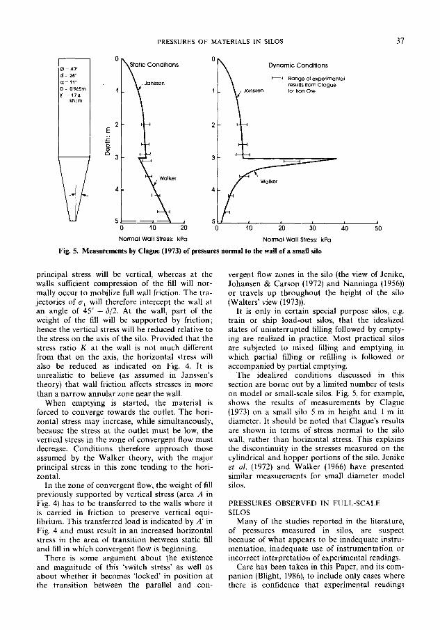
Fig. 5. Measurements by Clague (1973) of pressures normal to the wall of a small silo
principal stress will be vertical, whereas at the walls sufficient compression of the fill will nor- mally occur to mobilize full wall friction. The tra- jectories of (rl will therefore intercept the wall at an angle of 4.5” + 6/2. At the wall, part of the weight of the fill will be supported by friction; hence the vertical stress will be reduced relative to the stress on the axis of the silo. Provided that the stress ratio K at the wall is not much different from that on the axis, the horizontal stress will also be reduced as indicated on Fig. 4. It is unrealistic to believe (as assumed in Janssen’s theory) that wall friction affects stresses in more than a narrow annular zone near the wall.
When emptying is started, the material is forced to converge towards the outlet. The hori- zontal stress may increase, while simultaneously, because the stress at the outlet must be low, the vertical stress in the zone of convergent flow must decrease. Conditions therefore approach those assumed by the Walker theory, with the major principal stress in this zone tending to the hori- zontal.
In the zone of convergent flow, the weight of fill previously supported by vertical stress (area A in Fig. 4) has to be transferred to the walls where it is carried in friction to preserve vertical equi- librium. This transferred load is indicated by A’ in Fig. 4 and must result in an increased horizontal stress in the area of transition between static fill and fill in which convergent flow is beginning.
There is some argument about the existence and magnitude of this ‘switch stress’ as well as about whether it becomes ‘locked’ in position at the transition between the parallel and con-
vergent flow zones in the silo (the view of Jenike, Johansen & Carson (1972) and Nanninga (1956)) or travels up throughout the height of the silo (Walters’ view (1973)).
It is only in certain special purpose silos, e.g. train or ship load-out silos, that the idealized states of uninterrupted filling followed by empty- ing are realized in practice. Most practical silos are subjected to mixed filling and emptying in which partial filling or refilling is followed or accompanied by partial emptying.
The idealized conditions discussed in this section are borne out by a limited number of tests on model or small-scale silos. Fig. 5, for example, shows the results of measurements by Clague (1973) on a small silo 5 m in height and 1 m in diameter. It should be noted that Clague’s results are shown in terms of stress normal to the silo wall, rather than horizontal stress. This explains the discontinuity in the stresses measured on the cylindrical and hopper portions of the silo. Jenike et al. (1972) and Walker (1966) have presented similar measurements for small diameter model silos.
PRESSURES OBSERVED IN FULL-SCALE SILOS
Many of the studies reported in the literature, of pressures measured in silos, are suspect because of what appears to be inadequate instru- mentation, inadequate use of instrumentation or incorrect interpretation of experimental readings.
Care has been taken in this Paper, and its com- panion (Blight, 1986), to include only cases where there is confidence that experimental readings
38 BLIGHT
bh = MEASURED HORIZONTAL PRESSJRE:kPa
300
350
d (Cd on concrete) = 36”
K, = 0.55 KA=0.22 100
150
200
250
300
350
c
0
\\ l \
\ l
4 \ \ 0.4m
\ wall
Lt
\
l A
L
50 100 150 200
stmt 01 centric filling by
belt conveyor and st.Wte~ emPtying
-+ 20m DIA
rrching KO
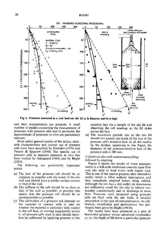
Fig. 6. Pressures measured in a coal load-out silo 20 m in diameter and 54 m high
and their interpretation are accurate. A small number of studies concerning the measurement of pressures with pressure cells and in particular the measurement of pressures in silos are particularly relevant.
sensitive face via a sample of the silo fill and observing the cell readings as the fill slides across the face.
(4
Most useful general studies of the action, desir- able characteristics and correct use of pressure cells have been described by Hvorslev (1976) and Peattie & Sparrow (1954). The specific use of pressure cells to measure pressures in silos has been studied by Askegaard (1963) and by Blight (1983).
The maximum particle size in the silo fill should not exceed one-tenth of the size of the pressure cell’s sensitive face: in all the studies by the Author, appearing in this Paper, the diameter of the pressure-sensitive face of the pressure cells is 200 mm.
Cylindrical silos with uninterruptedfilling followed by emptying
The following are particularly important points.
Figure 6 shows the results of stress measure- ments in a full-scale reinforced concrete mass flow coal silo used to load trains with export coal. This is one of the special purpose silos referred to earlier which is filled without interruption and then completely emptied before being refilled. Although the silo has a slot outlet, its dimensions are sufficiently small for the silo to behave rea- sonably concentrically and to discharge in mass flow. Pressures were measured using pressure cells set flush with the silo walls. A detailed description of the type of instrumentation, its cali- bration, installation and performance has pre- viously been given by Blight (1983b).
(4
(b)
(4
The face of the pressure cell should be as coplanar as possible with the inside of the silo wall and should have a similar surface texture to that of the wall. The stiffness of the cell should be as close to that of the wall as possible: in practice this means that the pressure cell should be as incompressible as possible. The calibration of a pressure cell depends on the material in contact with it, and on whether the material is stationary with respect to the cell face, or moving tangentially across it: all pressure cells used in silos should there- fore be calibrated by applying pressure to the
The results have been presented as a plot of horizontal pressure versus calculated overburden yz, i.e. the depth of fill above a particular pressure

PRESSURES OF MATERIALS IN SILOS
MEASURED HORIZONTAL PRESSUREkPa
39
centnc filling by belt conveyor
160 L’pressife
to;:::~,et 9 9 52 2
Fig. 7. Pressures measured in a coal load-out silo 20 m in diameter and 32 m high
cell times the bulk density of the fill. The param- eters y, C#J, 6 and K, were determined using estab- lished soil mechanics test methods (Blight & Ofer, 1984).
It will be seen that the results exhibit a con- siderable scatter corresponding to a slight varia- bility in the coal, segregation of particle sizes, etc. For design, therefore, it would be desirable to seek a relationship between overburden and hori- zontal pressure that provides a containing envelope to the measurements. For uninterrupted filling, the arching theory (Janssen’s theory with K = K,) fits the mean of the measurements rea- sonably well. A significant number of measured pressures are large enough to fall outside the envelope defined by
0h = K,yz (5a)
Only two, however, fall outside the envelope defined by
rJh = K,yz (5b)
This confirms the expectation, noted earlier, that stress conditions in a silo will approach the at-rest state during filling.
Turning to conditions at the start of emptying, it will be seen that the scatter of observations increases, but similar conclusions apply-the Janssen theory with K = K, gives a good fit to
the observations but equation (5b) gives a better containing envelope.
It should be noted from Fig. 6 that horizontal pressures generally increase moderately at the start of emptying. However, there is no dramatic increase such as might result in the failure of an otherwise adequately designed silo.
Figure 7 shows similar data for a second rein- forced concrete coal load-out bin. (This bin and its instrumentation have been fully described by Blight & Midgley (1980)). The bin is more complex than the first because, although it is filled concentrically, it has two outlets, only one of which can be used at a time. The silo therefore discharges in funnel or core flow with some of the flowing material bounded by the silo wall and the rest by dead material.
The pattern of the results is very similar to that of Fig. 6, with Janssen’s theory for K = K, giving a good fit to the observations and equation (5b) providing an adequate containing envelope.
Again, there is a moderate increase in pressure at the start of emptying. Also, at the start of emptying, horizontal pressures are reduced by the proximity of the outlet and modified by the onset of funnel flow, as indicated in Fig. 7.
Figure 8 shows a set of measurements for a third reinforced concrete silo subjected to unin- terrupted filling followed by emptying. It is an

40 BLIGHT
MEASURED HORIZONTAL PRESSUREXPa
20 MATERIAL: ASBESTOS ORE
80
no arching
1 6o i,chaup arching
C5 yo
0 20 40 60 eccentric filling by
belt conveyor
probable limit - Oflive
material
2m wide
I- diom&al slot opening
Fig. 8. Pressure measured in an asbestos ore silo 7 m in diameter and 24 m high
asbestos storage silo that is filled eccentrically because the head pulley of the filling conveyor is located concentrically and no allowance was made for the trajectory of the falling ore. It is also emptied eccentrically by means of a diametral slot across the whole of its flat bottom. In this case, the instrumentation consisted of strain gauges mounted on the hoop reinforcing of the silo. The pressures shown in Fig. 8 were calculated from the measured hoop strains. This procedure has previously been justified experimentally (Blight, Schaffner & Gilbert, 1982). The results for this silo are similar to those for the first two cases. The arching theory with K = K, provides a line of good fit to the data for uninterrupted filling, while equation (5a) provides a reasonable con- taining envelope. At the start of emptying the arching theory again provides a line of good fit (with K having a value between K, and K,), but equation (5b) provides a reasonable containing envelope.
Figure 9 refers to the fourth case of uninter- rupted filling followed by emptying. The data have been abstracted from Hartlen et al. (1984). This reinforced concrete silo, used for storing barley and wheat grain, has a much larger ratio of height to diameter than in the previous cases, and arching of the fill could therefore be expected to have a greater influence on lateral pressures.
This was certainly so for uninterrupted filling, although equation (5a) provides a good contain- ing envelope to the data. The pressures at the start of emptying obviously increased. The arching envelopes do not fit the data well, but equation (5b) contains it. In this case, it should be noted that the large pressures recorded at a calcu- lated overburden of 220 kPa probably coincide with the start of funnel flow to the outlet. Here, the increase in lateral pressure coefficient caused by convergent flow has more than offset the pressure-reducing effect of the outlet.
Cylindrical silo subjected to mixedJilling and emptying
Many silos are daily subjected to partial filling or emptying or simultaneous filling and emptying. Therefore stress states in the silo cannot be neatly divided into filling and emptying categories. Results for one such silo, a 20 m dia. steel maize grain storage facility, are shown in Fig. 10. The silo, its instrumentation and performance have been described by Blight (1983a).
The measured pressures are subject to far more scatter than in the previous cases, although the Janssen theory with K = K, again provides a line of good average fit to the data.
Being a steel silo which responds rapidly to changes in ambient temperature, the pressures are

PRESSURES OF MATERIALS IN SILOS 41
MEASURED HORIZONTAL PRESSUREIkPa
50 IW 150 200 1 8 O0 50 100 150 200
unintenupted filling
MAIERIAL: WHEAT
\ AND BARLEV
\ 5 = 7.8 kN/“V
I \ 4= 31” (taley)
\ \ 0 = 24” (wheat)
d(tieat on concrete) = 24”
‘b start ot
\’ emptying
50 - \\
\’
&\
100 - \’
\’ \
’ \
ISO- ” \ \
\ \
\ \
200 - o---o\ \
\ \
0 \ b
\ \ pipe
250 - o d ‘\ \
’ +
dec gra,n
Fig. 9. Measurements by Hartlen et al. (1984) of pressures in a grain silo 7 m in diameter and 46 m higb
MEASURED HORIZONTAL PRESSURE:kPa
50
0 mixed filling and emptying
MATERW: MAIZE GRAIN @ 8 = 7.5 kNInI
d= (maize on steel) = 16” a KA = 0.33 KJNC) = 0.6
@,Q \ \“, ‘, /’ plate thickness varies I2mm at _ base to 5”Im
43.2m
ot ttt material
1 o//b \ h ---iv
/ “; reduction ot
\ \ \ \ \
.\ I \ \ \ \ l-- Outlet
central grain
presure I” \
tunnel flow \ arching
k
.\
zO”e KO
)_
/$‘ no arching i
d S
10. Pressures measured in a maize storage silo 20 m in diameter and 432 m high
46m
42 BLIGHT
line 2
IJ WJges
!j ! upper limit
“hung ” COOI
positions 0
pressure
C&IS
I 5m
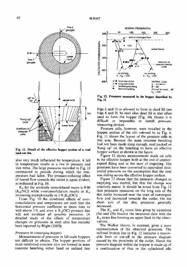
Fig. 11. Detail of the effective hopper section of a coal load-out bin.
also very much influenced by temperature. A fall in temperature results in a rise in pressure and vice versa. The large pressures recorded in Fig. 10 correspond to periods during which the tem- perature had fallen. The pressure-reducing effect of funnel flow towards the outlet is again evident, as indicated in Fig. 10.
K, for the normally consolidated maize is 0.60 (K&NC)) while overconsolidation results in K, increasing asymptotically to 1.0 (K,(OC)).
From Fig. 10 the combined effects of over- consolidation and temperature are such that the horizontal pressure coefficient at times rises to well above 1.0, and even a K,(OC) pressure line will not envelope all possible pressures. (A detailed study of the effects of temperature changes on pressures in steel silos has recently been reported by Blight (1985)).
Pressures in converging hoppers Measurements of pressures in full-scale hoppers
are difficult to obtain. The hopper portions of most reinforced concrete silos are formed in mass concrete benching either lined or unlined (see
NORMAL PRESSURE:kPa
PalO 50 100 150 200 250
_ _t~+???zYgY”ow - - - -qy?a l h
Fig. 12. Pressures measured in the hopper described by Fig. 11
Figs 6 and 7) or allowed to form in dead fill (see Figs 8 and 9). In steel silos dead fill is also often used to form the hopper (Fig. 10). Hence it is difficult or impossible to install pressure- measuring devices.
Pressure cells, however, were installed in the hopper section of the silo referred to in Fig. 6. Fig. 11 shows the layout of the pressure cells in this area. Because the mass concrete benching had not been made steep enough, coal packed or ‘hung up’ on the benching to form an effective hopper surface as shown in the figure.
Figure 12 shows measurements made on cells in the effective hopper both at the end of uninter- rupted filling and at the start of emptying. The pressures have been converted to equivalent hori- zontal pressures on the assumption that the coal was sliding across the effective hopper surface.
Figure 12 shows that the pressures changed as emptying was started, but that the change was relatively minor. It should be noted from Fig. 12 that pressures measured on the long axis of the slot outlet increased near the start of convergent flow and decreased towards the outlet. On the short axis of the slot, pressures generally decreased.
The K, and K, stress lines given by equations (5a) and (5b) bracket the measured data with the K, stress line forming an upper limit to the obser- vations.
The Walker theory, in contrast, gives a poor representation of the observed pressures. The inclined broken line in Fig. 12 indicates a reason- able limit or cut-off to the pressure diagram caused by the proximity of the outlet. Hence the pressure diagram within the hopper is made up of a continuation of that in the cylindrical silo
PRESSURES OF MATERIALS IN SILOS
limits of drawdown cone
43
drawoff only throug
7m MATERIAL: COAL Y = 0.5 kN/m’ @ = 39” d= (Coal on concrete) = KA = 0.23 Ko = 0.6
HORIZONTAL PREWJRE:kPa
reduction of pressure
towards outlet
29”
measurements (filling and
emptving)
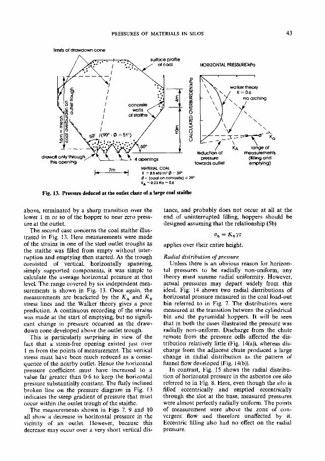
Fig. 13. Pressure deduced at the outlet chute of a large coal stnithe
above, terminated by a sharp transition over the tance, and probably does not occur at all at the lower 1 m or so of the hopper to near zero press- end of uninterrupted filling, hoppers should be ure at the outlet. designed assuming that the relationship (5b)
The second case concerns the coal staithe illus- trated in Fig. 13. Here measurements were made of the strains in one of the steel outlet troughs as the staithe was filled from empty without inter- ruption and emptying then started. As the trough consisted of vertical, horizontally spanning, simply supported components, it was simple to calculate the average horizontal pressure at that level. The range covered by six independent mea- surements is shown in Fig. 13. Once again, the measurements are bracketed by the K, and K, stress lines and the Walker theory gives a poor prediction. A continuous recording of the strains was made at the start of emptying, but no signifi- cant change in pressure occurred as the draw- down cone developed above the outlet trough.
r7h = K,yz
applies over their entire height.
Radial distribution of pressure
This is particularly surprising in view of the fact that a stress-free opening existed just over 1 m from the points of measurement. The vertical stress must have been much reduced as a conse- quence of the nearby outlet. Hence the horizontal pressure coefficient must have increased to a value far greater than 0.6 to keep the horizontal pressure substantially constant. The flatly inclined broken line on the pressure diagram in Fig. 13 indicates the steep gradient of pressure that must occur within the outlet trough of the staithe.
Unless there is an obvious reason for horizon- tal pressures to be radially non-uniform, any theory must assume radial uniformity. However, actual pressures may depart widely from this ideal. Fig. 14 shows two radial distributions of horizontal pressure measured in the coal load-out bin referred to in Fig. 7. The distributions were measured at the transition between the cylindrical bin and the pyramidal hoppers. It will be seen that in both the cases illustrated the pressure was radially non-uniform. Discharge from the chute remote from the pressure cells affected the dis- tribution relatively little (Fig. 14(a)), whereas dis- charge from the adjacent chute produced a large change in radial distribution as the pattern of funnel flow developed (Fig. 14(b)).
The measurements shown in Figs 7, 9 and 10 all show a decrease in horizontal pressure in the vicinity of an outlet. However, because this decrease may occur over a very short vertical dis-
In contrast, Fig. 15 shows the radial distribu- tion of horizontal pressure in the asbestos ore silo referred to in Fig. 8. Here, even though the silo is filled eccentricahy and emptied eccentrically through the slot at the base, measured pressures were almost perfectly radially uniform. The points of measurement were above the zone of con- vergent flow and therefore unaffected by it. Eccentric filling also had no effect on the radial pressure.

44 BLIGHT
I 50 kPa 1
-----_
L North chute discharging
5OkPa I
start of emptying
) South chute discharging
(b)
Fig. 14. Radial distribution of horizontal pressure in a coal storage silo
Effects of eccentricjow Funnel flow, such as that which takes place in
the coal load-out bin referred to in Figs 7 and 14, or plug flow (see Fig. l), results in a radial non- uniformity of horizontal pressure. The simplest mechanistic explanation of this phenomenon is that given by Jenike (1967): Fig. 16 represents a silo of internal diameter D in which plug or funnel flow is taking place over a diameter d. The flow zone impinges on the silo wall. Applying equation (1) to the static and flowing zones of fill
Hence
DY a --
hD - 4 tan 6
ahd d -=_ D OhD
(64
Thus the horizontal pressure in the flowing fill will be less than that in the static fill and addi- tional forces Q will have to be generated by hori- zontal friction along the walls of the silo to maintain horizontal equilibrium.
Turning again to the silo illustrated in Fig. 7, when the silo is emptied through one chute, the
MEASURED HORIZONTAL PRESSUREkPa
Fig. 15. Radial distribution of horizontal pressure in an asbestos ore silo
horizontal pressure on the wall adjacent to that chute should decrease. This effect is shown in Fig. 17. Pressure cells Al-A4 are mounted on line A (see Fig. 7) adjacent to the south chute. Line A fell within the zone of funnel flow and pressures would therefore be expected to decrease. Line B fell just outside the funnel flow zone so that press- ures would not be expected to change by much.
In Fig. 17 the numbers 1-3 each represent one series of measurements. As the figure shows, the expectations expressed above were realized, except at gauge A4, where there was an unex- plained slight increase in pressure. Although there is qualitative agreement with the predictions of equation (5c), it is difficult to check on the quanti- tative agreement. However, the diameter of the funnel flow zone must decrease with increasing depth z and therefore the decrease in pressure along line A should increase with z. As Fig. 17 shows, this was so.
Occurrence of switch pressures Clague’s (1973) model test data (Fig. 5) as well
as those of Jenike et nl. (1972) (and others) show what appear to be clearly defined and relatively
\ fill static
Fig. 16. Effects of funnel or plug flow on horizontal pressure in a silo
PRESSURES OF MATERIALS IN SILOS 45
CHANGE OF PRESSURE AT START OF EMPTYING FROM SOUTH CHUTE A p/KoXZ
Decrease Increase -50 , i +5i” li i +5q
N
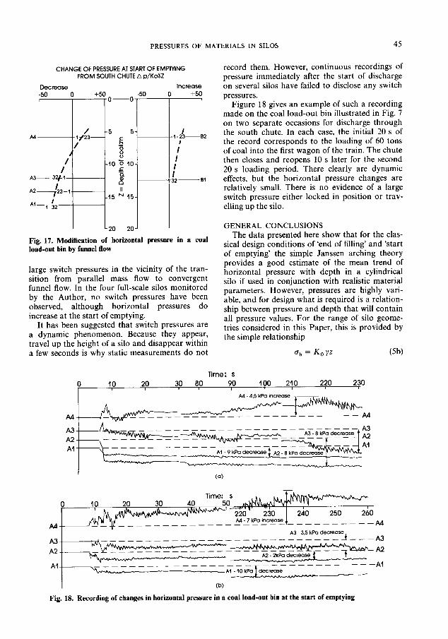
Fig. 17. Modification of horizontal pressure in a coal load-out bin by funnel flow
large switch pressures in the vicinity of the tran- sition from parallel mass flow to convergent funnel flow. In the four full-scale silos monitored by the Author, no switch pressures have been observed, although horizontal pressures do increase at the start of emptying.
It has been suggested that switch pressures are a dynamic phenomenon. Because they appear, travel up the height of a silo and disappear within a few seconds is why static measurements do not
record them. However, continuous recordings of pressure immediately after the start of discharge on several silos have failed to disclose any switch pressures.
Figure 18 gives an example of such a recording made on the coal load-out bin illustrated in Fig. 7 on two separate occasions for discharge through the south chute. In each case, the initial 20 s of the record corresponds to the loading of 60 tons of coal into the first wagon of the train. The chute then closes and reopens 10 s later for the second 20 s loading period. There clearly are dynamic effects, but the horizontal pressure changes are relatively small. There is no evidence of a large switch pressure either locked in position or trav- elling up the silo.
GENERAL CONCLUSIONS The data presented here show that for the clas-
sical design conditions of ‘end of filling’ and ‘start of emptying’ the simple Janssen arching theory provides a good estimate of the mean trend of horizontal pressure with depth in a cylindrical silo if used in conjunction with realistic material parameters. However, pressures are highly vari- able, and for design what is required is a relation- ship between pressure and depth that will contain all pressure values. For the range of silo geome- tries considered in this Paper, this is provided by the simple relationship
Oh = K,yz (5b)
0 10 20 lime: S
30 80 90 100 210 220 230 I
AA 4.5 kPa increase
--. -- ----
(b)
Fig. 18. Recording of changes in horizontal pressure in a coal load-out bin at the start of emptying

46 BLIGHT
in which K, is the at-rest pressure coefhcient for the normally consolidated til.
This relationship provides an envelope to the pressures that are likely to occur in hoppers and the hopper portions of silos. The Walker arching theory for convergent containers has not been found to fit observed pressures.
In silos subjected to mixed filling and empty- ing, horizontal pressures may far exceed those experienced at the start of emptying after uninter- rupted filling. This is particularly so for steel silos in which pressures are much affected by tem- perature cycles. Here equation (Sb), in which K, is the at-rest pressure coefticient for the over- consolidated fill, will contain most, but not neces- sarily all, expected pressures.
Horizontal pressures in silos are not necessarily radially uniform as assumed in theory. If non- uniformity is caused by a predictable flow condi- tion, e.g. funnel flow to an eccentric outlet, the effects of the flow on pressure can be predicted, at least qualitatively.
Horizontal pressures generally increase at the start of emptying. However, the increase is mod- erate and significant switch pressures have not, as far as is known, been observed in full-scale silos.
These conclusions are essentially the same as those reached for silos used to store fine powders (Blieht. 1986).
REFERENCES American Concrete Institute Committee 313 (1975).
Recommended practice for design and construction of concrete bins, silos and bunkers for storing granu- lar materials. Am. Concr. Inst. .I. 71, Oct. 529-565.
Askegaard, V. (1963). Measurement of pressure in solids by means of pressure cells. Bulletin 17, Structural Research Laboratory, Technical University of Denmark.
Blight, G. E. (1983a). Performance of a 20 m diameter steel maize storage bin. Proc. 2nd Int. Co@ Design ofSilosfor Strength and Flow, pp. 179-191. London: Powder Advisory Centre.
Blight, G. E. (1983b). Measuring pressures in silos with pressure cells. Proc. 2nd Int. Conf Design of Silos for Strength and Flow, pp. 217-229. London: Powder Advisory Centre.
Blight, G. E. (1985). Temperature changes affect press- ures in steel bins. Int. J. Bulk Solids Stor. Silos 1, NO. 4.
Blight. G. E. (1986). Pressures exerted by materials stored in silos: part II, fine powders. &otechnique 36, No. 1, 47756.
Blight, G. E. & Midgley, D. (1980). Pressure measured in a 20 m diameter coal load-out bin. Proc. Int. ConiI Desian of Silos for Strength and Flow 1. London: Powder Advisory Centre:
Blight, G. E. & Ofer, Z. (1984). Laboratory determi- nation of K, and comparison with prototype silo
observations. Proc. 4th Aust.-N.Z. Con& Geo- mechanics, Perth 1, 83-87.
Blight, G. E., Schaffner, R. H. & Gilbert, B. (1982). Strains in a reinforced concrete silo during rapid filling. with a fine powder. J. Powd. Bulk Solids Tech;oi. 6, 17-27. _
Clague, K. (1973) The effects of stresses in bunkers. PhD thesis, University of Nottingham.
Hartlen, J., Nielsen, J. & Ljunggren, L. (1984). The wall pressure in large grain silos. Stockholm: Swedish Council for Building Research.
Hvorslev, M. J. (1976). The changeable interaction between soils and pressure cells: tests and reviews at the Waterways Experiment Station. Technical Report S-76-7, US Army Engineer Waterways Experiment Station.
Janssen, H. A. (1895). Versuche iiber Getreidedruck in Silozellen. Z. Ver. Dt. Ing., 1045-1050.
Jenike, A. W. (1967). Denting of circular bins with eccentric drawpoints. J. Strut. Div. Am. Sot. Cio. Engrs 93, STl, 27-35.
Jenike, A. W. (1980). Effect of solids flow properties and the hopper-feeder unit on silo loads. Proc. Int. Conf Design of Silos for Strength and Flow 1. London: Powder Advisory Centre.
Jenike, A. W., Johansen, J. R. & Carson, J. W. (1972). Bin loads part 3: mass-flow bins. J. Engng Ind. Am. Sot. Mech. Engrs, l-7.
Martens, P. (1980). DIN 1055 part 6: The performance of the old norm and a progress report on the revised edition. Proc. Int. Co& Design of Silos for Strength and Flow 1. London: Powder Advisory Centre.
Nanninga, K. (1956). Gibt die iibliche Berechnungsart der Driicke auf die Wande und den Boden von Silo- bauten sichere Ergebenisse. Ingenieur, Nov.
Nielsen, J. & Kristiansen, N. 0. (1980). Related mea- surements of pressure and conditions in full-scale barley silo and in model silo. Proc. Int. Con& Design of Silos for Strength and Flow 1, 22. London: Powder Advisory Centre.
Peattie, K. R. & Sparrow, R. R. (1954). The fundamen- tal action of earth pressure cells. J. Mech. Phys. Solids 2, 141-155.
Ravenet, J. (1981). Silo problems. Bulk Solids Handl. 1, No. 4,667-679.
Reimbert, M. & Reimbert, A. (1956). Silos, traiti thCo- rique et pratique. Paris: Eyrolles.
Sadler, J. S. (1980). Silo problems. Proc. Int. Con& Design of Silos for Strength and Flow. 1, 2. London: Powder Advisory Centre.
Theimer, 0. F. (1969). Failures of reinforced concrete grain silos. Trans. Am. Sot. Mech. Enyrs, 46&477.
Walker, D. M. (1966). An approximate theory for press- ures and arching in hoppers. Chem. Enyng Sci. 21, 975-997.
Walters, J. K. (1973). A theoretical analysis of stresses in axially-symmetric hoppers and bunkers. Chem. Enyng Sci. 28, 13-20.
Wigram, S. (1980). Report on an inventory of Swedish grain silos. Proc. Int. Conf. Design of Silos for Strength and Flow 1. London: Powder Advisory Centre.