ge 10 lsx - mosaenergia.com electrogenos/ge_10_… · nome e indirizzo della persona autorizzata a...
TRANSCRIPT

© MOSA 12/10/10 34010M00preparato da UPTapprovato da DITE
USE AND MAINTENANCE MANUAL SPARE PARTS CATALOG
340109003 - GB1 0 1 2
GE 10 LSX

GE 10 LSXDESCRIPTION OF THE MACHINEM0
REV.1-10/12
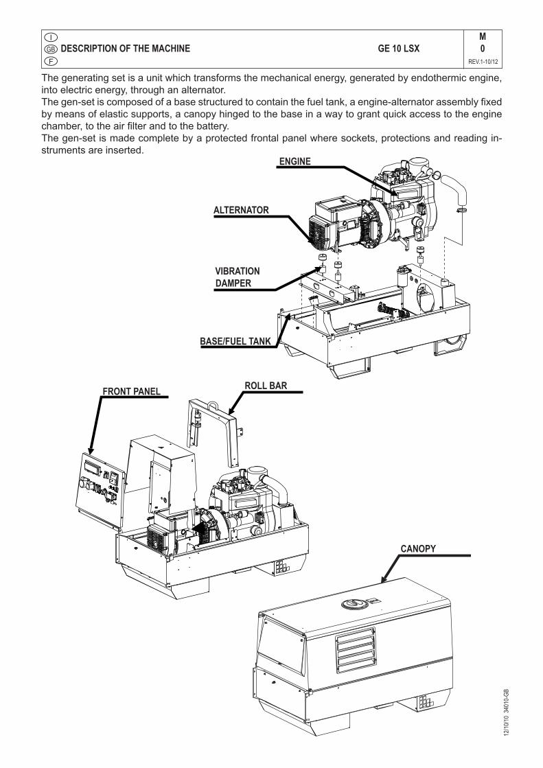
The generating set is a unit which transforms the mechanical energy, generated by endothermic engine, into electric energy, through an alternator.The gen-set is composed of a base structured to contain the fuel tank, a engine-alternator assembly fixed by means of elastic supports, a canopy hinged to the base in a way to grant quick access to the engine chamber, to the air filter and to the battery.The gen-set is made complete by a protected frontal panel where sockets, protections and reading in-struments are inserted.
12/10
/10 3
4010
-GB
ROLL BAR
CANOPY
FRONT PANEL
BASE/FUEL TANK
VIBRATIONDAMPER
ALTERNATOR
ENGINE

Quality systemM01
REV.4-03/12
UNI EN ISO 9001 : 2008
10/1
0/02
M01
-GB
MOSA has certified its quality system according to UNI EN ISO 9001:2008 to ensure a constant, highquality of its products. This certification covers thedesign, production and servicing of engine dri-venwelders and generating sets.
The certifying institute, ICIM, which is a member ofthe International Certification Network IQNet, awarded the official approval to MOSA after an-examination of its operations at the head office andplant in Cusago (MI), Italy.
This certification is not a point of arrival but a pledgeon the part of the entire company to maintain a levelof quality of both its products and services whichwill continue to satisfy the needs of its clients, aswell as to improve the transparency and thecom-munications regarding all the company’s activesin accordance with the official procedures and inhar-mony with the MOSA Manual of Quality.
The advantages for MOSA clients are:·Constant quality of products and services at thehigh level which the client expects;· Continuous efforts to improve the products andtheir performance at competitive conditions;
· Competent support in the solution of problems;· Information and training in the correct applicatio-nand use of the products to assure the security ofthe operator and protect the environment;
· Regular inspections by ICIM to confirm that the-requirements of the company’s quality systemand ISO 9001 are being respected.
All these advantages are guaranteed by the CER-TIFICATE OF QUALITY SYSTEM No.0192 issued by ICIM S.p.A. - Milano (Italy ) - www.icim.it
12/10
/10 3
4010
-GB
GE 10 LSXM1
REV.0-10/10
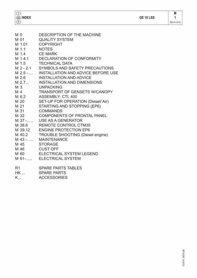
INDEX
M 0 DESCRIPTION OF THE MACHINEM 01 QUALITY SYSTEMM 1.01 COPYRIGHTM 1.1 NOTESM 1.4 CE MARKM 1.4.1 DECLARATION OF CONFORMITYM 1.5 TECHNICAL DATAM 2 - 2.1 SYMBOLS AND SAFETY PRECAUTIONSM 2.5 -…. INSTALLATION AND ADVICE BEFORE USEM 2.6 INSTALLATION AND ADVICEM 2.7... INSTALLATION AND DIMENSIONSM 3 UNPACKINGM 4 TRANSPORT OF GENSETS w/CANOPYM 6.2 ASSEMBLY: CTL 400M 20 SET-UP FOR OPERATION (Diesel/ Air)M 21 STARTING AND STOPPING (EP6)M 31 COMMANDSM 32 COMPONENTS OF FRONTAL PANELM 37 -….. USE AS A GENERATORM 38.6 REMOTE CONTROL CTM35M 39.12 ENGINE PROTECTION EP6M 40.2 TROUBLE SHOOTING (Diesel engine)M 43 -….. MAINTENANCEM 45 STORAGEM 46 CUST OFFM 60 ELECTRICAL SYSTEM LEGENDM 61-….. ELECTRICAL SYSTEM
R1 SPARE PARTS TABLESHK ... SPARE PARTSK... ACCESSORIES
CopyrightM1.01
REV.0-10/02
All rights are reserved to said Company.
It is a property logo of MOSA division of B.C.S. S.p.A. All other possible logos contained in the documen-tation are registered by the respective owners.
+ The reproduction and total or partial use, in any form and/or with any means, of the documen-tation is allowed to nobody without a written permission by MOSA division of B.C.S. S.p.A.
To this aim is reminded the protection of the author’s right and the rights connected to the creation and design for communication, as provided by the laws in force in the matter.
In no case MOSA division of B.C.S. S.p.A. will be held responsible for any damaga, direct or indirect, in relation with the use of the given information.
MOSA division of B.C.S. S.p.A. does not take any responsibility about the shown information on firms or individuals, but keeps the right to refuse services or information publication which it judges discutible, unright or illegal.
10/1
0/02
M1-
01-G
B
This use and maintenance manual is an important part of the machines in question.The assistance and maintenance personel must keep said manual at disposal, as well as that for the engine and alternator (if the machine is synchronous) and all other documentation about the machine.
We advise you to pay attention to the pages concerning the security (see page M1.1).
ATTENTION!
INFORMATION
Dear Customer,We wish to thank you for having bought a high quality set.
Our sections for Technical Service and Spare Parts will work at best to help you if it were necessary.
To this purpose we advise you, for all control and over-haul operations, to turn to the nearest authorized Service Centre, where you will obtain a prompt and specialized intervention.
+ In case you do not profit on these Services and some arts are replaced, please ask and be sure that are used exclusively original parts; this to guarantee that the performances and the initial safety prescribed by the norms in force are re-established.
+The use of non original spare parts will cancel immediately any guarantee and Technical Service obligation.
NOTES ABOUT THE MANUALBefore actioning the machine please read this manual attentively. Follow the instructions contained in it, in this way you will avoid inconveniences due to negligence, mistakes or incorrect maintenance. The manual is for qualified personnel, who knows the rules: about safety and health, installation and use of sets movable as well as fixed.
You must remember that, in case you have difficulties for use or installation or others, our Technical Service is always at your disposal for explanations or interventions.
The manual for Use Maintenance and Spare Parts is an integrant part of the product. It must be kept with care during all the life of the product.In case the machine and/or the set should be yielded to another user, this manual must also given to him.Do not damage it, do not take parts away, do not tear pages and keep it in places protected from dampness and heat.
You must take into account that some figures contained in it want only to identify the described parts and therefore might not correspond to the machine in your possession.
INFORMATION OF GENERAL TYPEIn the envelope given together with the machine and/or set you will find: the manual for Use Maintenance and Spare Parts, the manual for use of the engine and the tools (if included in the equipment), the guarantee (in the countries where it is prescribed by law).
Our products have been designed for the use of gene-ration for welding, electric and hydraulic system; ANY OTHER DIFFERENT USE NOT INCLUDED IN THE ONE INDICATED, relieves the manufacturer from the risks which could happen or, anyway, from that which was agreed when selling the machine. The manufacturer excludes any responsibility for damages to the machine, to the things or to persons in this case.
Our products are made in conformity with the safety norms in force, for which it is advisable to use all these devices or information so that the use does not bring damage to persons or things.
While working it is advisable to keep to the personal safety norms in force in the countries to which the product is destined (clothing, work tools, etc.).
Do not modify for any motive parts of the machine (faste-nings, holes, electric or mechanical devices, others..) if not duly authorized in writing: the responsibility coming from any potential intervention will fall on the executioner as in fact he becomes maker of the machine.
NotesM1-1
REV.0-10/02
+ Notice: this manual does not engage the manufacturer, who keeps the faculty, apart the essential characte-ristics of the model here described and illustrated, to bring betterments and modifications to parts and accessories, without putting this manual uptodate immediately.
10/1
0/02
M 1
-1 G
B_N
EU
TRO
CE MARKM
1.4 REV.5-03/11
10/1
0/02
M1-
4 G
B
Any of our product is labelled with CE marking attesting its conformity to appliable directives and also the fulfillment of safety requirements of the product itself; the list of these directives is part of the declaration of conformity included in any machine standard equipment. Here below the adopted symbol:
CE marking is clearly readable and unerasable and it can be either part of the data-plate.
Furthermore, on each model it is shown the noise level value; the symbol used is the following:
The indication is shown in a clear, readable and indeleble way on a sticker.
04/06
/10 M
1.4.1
Dichiarazione conformitàDeclaration of conformityDéclaration de conformité
M1.4.1
REV.0-06/10
MM 083.0
BCS S.p.A. Sede legale: Via Marradi 1
20123 Milano - Italia
Stabilimento di Cusago, 20090 (MI) - Italia
V.le Europa 59 Tel.: +39 02 903521
Fax: +39 02 90390466
DICHIARAZIONE DI CONFORMITA'
Déclaration de Conformité – Declaration of Conformity – Konformitätserklärung Conformiteitsverklaring – Declaración de Conformidad
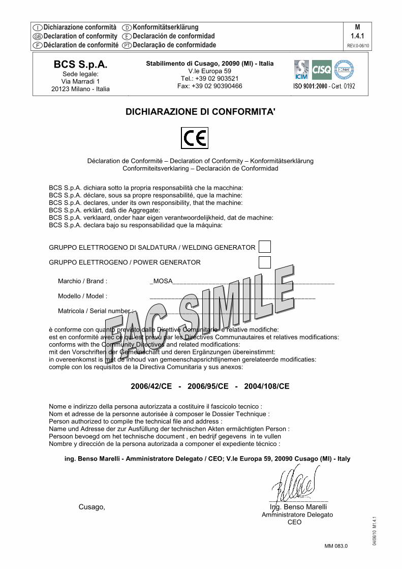
BCS S.p.A. dichiara sotto la propria responsabilità che la macchina: BCS S.p.A. déclare, sous sa propre responsabilité, que la machine: BCS S.p.A. declares, under its own responsibility, that the machine: BCS S.p.A. erklärt, daß die Aggregate: BCS S.p.A. verklaard, onder haar eigen verantwoordelijkheid, dat de machine: BCS S.p.A. declara bajo su responsabilidad que la máquina:
GRUPPO ELETTROGENO DI SALDATURA / WELDING GENERATOR GRUPPO ELETTROGENO / POWER GENERATOR
Marchio / Brand : _MOSA_____________________________________________
Modello / Model : ______________________________________________ Matricola / Serial number : ______________________________
è conforme con quanto previsto dalle Direttive Comunitarie e relative modifiche: est en conformité avec ce qui est prévu par les Directives Communautaires et relatives modifications: conforms with the Community Directives and related modifications: mit den Vorschriften der Gemeinschaft und deren Ergänzungen übereinstimmt: in overeenkomst is met de inhoud van gemeenschapsrichtlijnemen gerelateerde modificaties: comple con los requisítos de la Directiva Comunitaria y sus anexos:
2006/42/CE - 2006/95/CE - 2004/108/CE
Nome e indirizzo della persona autorizzata a costituire il fascicolo tecnico : Nom et adresse de la personne autorisée à composer le Dossier Technique : Person authorized to compile the technical file and address : Name und Adresse der zur Ausfüllung der technischen Akten ermächtigten Person : Persoon bevoegd om het technische document , en bedrijf gegevens in te vullen Nombre y dirección de la persona autorizada a componer el expediente técnico :
ing. Benso Marelli - Amministratore Delegato / CEO; V.le Europa 59, 20090 Cusago (MI) - Italy
_______________
Cusago, Ing. Benso Marelli Amministratore Delegato
CEO
02/0
1/97
DC
CN
FC
E1.
DO
C
KonformitätserklärungDeclaración de conformidadDeclaração de conformidade
12/10
/10 3
4010
-GB
Technical Data GE 10 LSXM
1.5REV.1-10/12
2000 / 14 / CE
2000 / 14 / CE
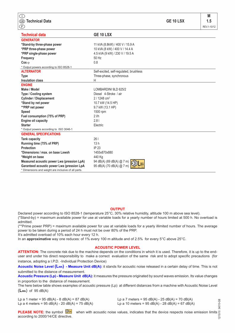
OUTPUTDeclared power according to ISO 8528-1 (temperature 25°C, 30% relative humidity, altitude 100 m above sea level).(*Stand-by) = maximum available power for use at variable loads for a yearly number of hours limited at 500 h. No overload is admitted. (**Prime power PRP) = maximum available power for use at variable loads for a yearly illimited number of hours. The average power to be taken during a period of 24 h must not be over 80% of the PRP. It’s admitted overload of 10% each hour every 12 h.In an approximative way one reduces: of 1% every 100 m altitude and of 2.5% for every 5°C above 25°C.
ACOUSTIC POWER LEVELATTENTION: The concrete risk due to the machine depends on the conditions in which it is used. Therefore, it is up to the end-user and under his direct responsibility to make a correct evaluation of the same risk and to adopt specific precautions (for instance, adopting a I.P.D. -Individual Protection Device)Acoustic Noise Level (LWA) - Measure Unit dB(A): it stands for acoustic noise released in a certain delay of time. This is not submitted to the distance of measurement.Acoustic Pressure (Lp) - Measure Unit dB(A): it measures the pressure originated by sound waves emission. Its value changes in proportion to the distance of measurement.The here below table shows examples of acoustic pressure (Lp) at different distances from a machine with Acoustic Noise Level (LWA) of 95 dB(A)
Lp a 1 meter = 95 dB(A) - 8 dB(A) = 87 dB(A) Lp a 7 meters = 95 dB(A) - 25 dB(A) = 70 dB(A)Lp a 4 meters = 95 dB(A) - 20 dB(A) = 75 dB(A) Lp a 10 meters = 95 dB(A) - 28 dB(A) = 67 dB(A)
PLEASE NOTE: the symbol when with acoustic noise values, indicates that the device respects noise emission limits according to 2000/14/CE directive.
Technical data GE 10 LSXGENERATOR*Stand-by three-phase power 11 kVA (8.8kW) / 400 V / 15.9 A*PRP three-phase power 10 kVA (8 kW) / 400 V / 14.4 A*PRP single-phase power 4.5 kVA (9 kW) / 230 V / 19.5 AFrequecy 50 HzCos ϕ 0.8* Output powers according to ISO 8528-1ALTERNATOR Self-excited, self-regulated, brushlessType Three-phase, synchronousInsulation class HENGINEMake / Model LOMBARDINI 9LD 625/2Type / Cooling system Diesel 4-Stroke / air Cylinder / Displacement 2 / 1248 cm3
*Stand by net power 10.7 kW (14.5 HP)**PRP net power 9.7 kW (13.1 HP)Speed 1500 rpmFuel consumption (75% of PRP) 2 l/hEngine oil capacity 2.8 lStarter Electric* Output powers according to ISO 3046-1
GENERAL SPECIFICATIONSTank capacity 26 lRunning time (75% of PRP) 13 hProtection IP 23*Dimensions / max. on base Lxwxh 1455x870x880*Weight on base 440 KgMeasured acoustic power Lwa (pression LpA) 94 dB(A) (69 dB(A) @ 7 m)Garanteed acoustic power Lwa (pression LpA 95 dB(A) (70 dB(A) @ 7 m)* Dimensions and weight are inclusive of all parts.
SYMBOLS AND SAFETY PRECAUTIONSM2
REV.0-11/99
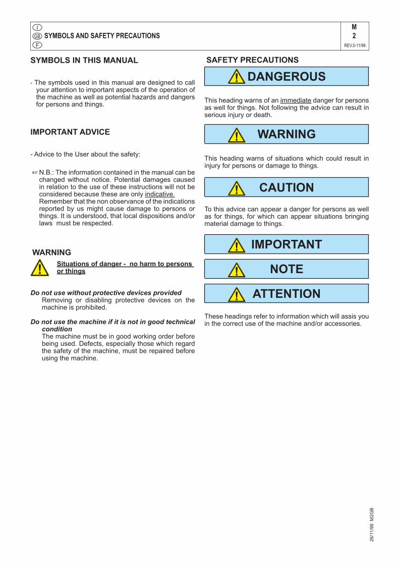
SYMBOLS IN THIS MANUAL
- The symbols used in this manual are designed to call your attention to important aspects of the operation of the machine as well as potential hazards and dangers for persons and things.
IMPORTANT ADVICE
- Advice to the User about the safety:
+ N.B.: The information contained in the manual can be changed without notice. Potential damages caused in relation to the use of these instructions will not be considered because these are only indicative.
Remember that the non observance of the indications reported by us might cause damage to persons or things. It is understood, that local dispositions and/or laws must be respected.
WARNINGSituations of danger - no harm to persons or things
Do not use without protective devices provided Removing or disabling protective devices on the
machine is prohibited.
Do not use the machine if it is not in good technical condition
The machine must be in good working order before being used. Defects, especially those which regard the safety of the machine, must be repaired before using the machine.
SAFETY PRECAUTIONS
This heading warns of an immediate danger for persons as well for things. Not following the advice can result in serious injury or death.
This heading warns of situations which could result in injury for persons or damage to things.
To this advice can appear a danger for persons as well as for things, for which can appear situations bringing material damage to things.
These headings refer to information which will assis you in the correct use of the machine and/or accessories.
!
26/1
1/99
M2G
B
WARNING
DANGEROUS
CAUTION
IMPORTANT
NOTE
ATTENTION
!
!
!
!
!
!

SYMBOLS AND SAFETY PRECAUTIONSM
2-1REV.2-06/10
SYMBOLS
STOP - Read absolutely and be duly attentive
Read and pay due attention
GENERAL ADVICE - If the advice is not respected damage can happen to persons or things.
HIGH VOLTAGE - Attention High Voltage.There can be parts in voltage, dangerous to touch. The non observance of the advice implies life danger.
FIRE - Danger of flame or fire. If the advice is not respected fires can happen.
HEAT - Hot surfaces. If the advice is not respected burns or damage to things can be caused.
EXPLOSION - Explosive material or danger of explosion. in general. If the advice is not respected there can be explosions.
WATER - Danger of shortcircuit. If the advice is not respected fires or damage to persons can be caused.
SMOKING - The cigarette can cause fire or explosion. If the advice is not respected fires or explosions can be caused.
ACIDS - Danger of corrosion. If the advice is not respected the acids can cause corrosions with damage to persons or things.
WRENCH - Use of the tools. If the advice is not respected damage can be caused to things and even to persons.
PRESSION - Danger of burns caused by the expulsion of hot liquids under pressure.
PROHIBITIONS No harm for persons Use only with safety clothing -
It is compulsory to use the personal protection means given in equip-ment.
Use only with safety clothing - It is compulsory to use the personal protection means given in equipment.
Use only with safety protections - It is a must to use protection means suitable for the different welding works.
Use with only safety material - It is prohibited to use water to quench fires on the electric machines.
Use only with non inserted voltage - It is prohibited to make interventions before having disinserted the voltage.
No smoking - It is prohibited to smoke while filling the tank with fuel.
No welding - It is forbidden to weld in rooms containing explosive gases.
ADVICE No harm for persons and things
Use only with safety tools, adapted to the specific use - It is advisable to use tools adapted to the various maintenance works.
Use only with safety protections, specifically suitable It is advisable to use protections suitable for the different welding works.
Use only with safety protections - It is advisable to use protections suitable for the different daily checking works.
Use only with safety protections - It is advisable to use all protections while shifting the machine.
Use only with safety protections -It is advisable to use protections suitable for the different daily checking works.and/or of maintenance.
!
26/1
1/99
M2-
1GB
ACCES FORBIDDEN to non authorizad peaple.

INSTALLATION AND ADVICE BEFORE USEM
2-5REV.0-06/00
The installation and the general advice concerning the operations, are finalized to the correct use of the ma-chine, in the place where it is used as generator group and/or welder.
!
+ FIRSTAID. In case the operator shold be sprayed by accident, from corrosive liquids a/o hot toxic gas or whatever event which may cause serious injuries or death, predispose the first aid in accordance with the ruling labour accident standards or of local instructions.
+ FIREPREVENTION. In case the working zone,for whatsoever cause goes on fire with flames liable to cause severe wounds or death, follow the first aid as described by the ruling norms or local ones.
10/0
6/00
M2-
5I
ENGINE
Stop engine when fueling
CHEC
KINGBOARD
Do not touch electric devices if you are barefoot or with wet clothes.Do not smoke, avoid flames, sparks or electric tools when fueling.
Unscrew the cap slowly to let out the fuel vapours. Always keep off leaning sur-faces during work operations.Slowly unscrew the cooling liquid tap if the liquid must be topped up.
The vapor and the heated cooling liquid under pressure can burn face, eyes, skin. Static electricity can demage the parts on the circuit.Do not fill tank completely.
Wipe up spilled fuel before starting engine. An electric shock can kill
Shut off fuel of tank when moving machine (where it is assembled).Avoid spilling fuel on hot engine.Sparks may cause the explosion of battery vapours
Skin contact Wash with water and soapEyes contact Irrigate with plenty of water, if the irritation persists contact a specialistIngestion Do not induce vomit as to avoid the intake of vomit into the lungs, send for a doctorSuction of liquids from lungs
If you suppose that vomit has entered the lungs (as in case of spontaneous vomit) take the subject to the hospital with the utmost urgency
Inhalation In case of exposure to high concentration of vapours take immediately to a non polluted zone the person involved
EXTINCTIONMEANSAppropriated Carbonate anhydride (or carbon dioxyde) powder, foam, nebulized waterNot to be used Avoid the use of water jetsOther indications Cover eventual shedding not on fire with foam or sand, use water jets to cool off the surfaces close to the fireParticular protection Wear an autorespiratory mask when heavy smoke is presentUseful warnings Avoid, by appropriate means to have oil sprays over metallic hot surfaces or over electric contacts
(switches,plugs,etc.). In case of oil sprinkling from pressure circuits, keep in mind that the inflamability point is very low.
WARNINGTHE MACHINE MUST NOT BE USED IN AREAS WITH EX-
PLOSIVE ATMOSPHERE
WARNING CAUTION
DANG
EROUS
!
!
!!

INSTALLATION AND ADVICEM
2.6REV.1-06/07
INSTALLATION AND ADVICE BEFORE USE
GASOLINE ENGINES+Use in open space, air swept or vent exhaust gases,
which contain the deathly carbone oxyde, far from the work area.
DIESEL ENGINES+ Use in open space, air swept or vent exhaust gases
far from the work area.
POSITIONPlace the machine on a level surface at a distance of at least 1,5 m from buildings or other plants.
Check that the air gets changed completely and the hot air sent out does not come back inside the set so as to cause a dangerous increase of the temperature.
+ Make sure that the machine does not move during the work: block it possibly with tools and/or devices made to this purpose.
Maximum leaning of the machine (in case of dislevel)
10°
10°� = 20° max
10°
10°� = 20° max
26/1
1/99
M2-
6GB
1,5 m
1,5 m
1,5m
GAS DI SCARICO
EXHAUST OUTPUT
MOVES OF THE MACHINE + At any move check that the engine is off, that there are
no connections with cables which impede the moves.
PLACE OF THE MACHINE
ATTENTIONFor a safer use from the operator DO NOT fit the machine in locations with high risk of flood.Please do not use the machine in weather conditions which are beyond IP protection shown both in the data plate and on page named "technical data" in this same manual.
!

InstallazioneInstallationInstallation
GE 20000 LS/GSGE 10 LSX
M2.7
REV.2-09/12
LuftzirkulationInstalación
17/0
9/07
250
20-I
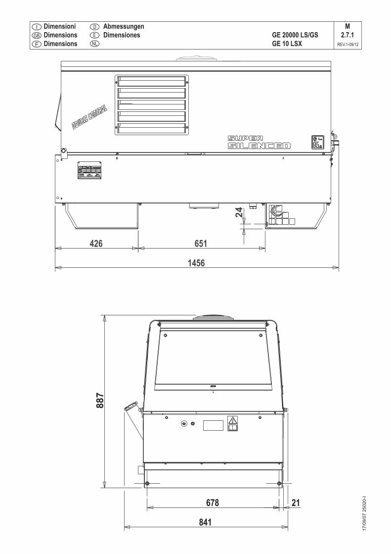
DimensioniDimensionsDimensions
AbmessungenDimensiones GE 20000 LS/GS
GE 10 LSX
M2.7.1
REV.1-09/12
17/0
9/07
250
20-I
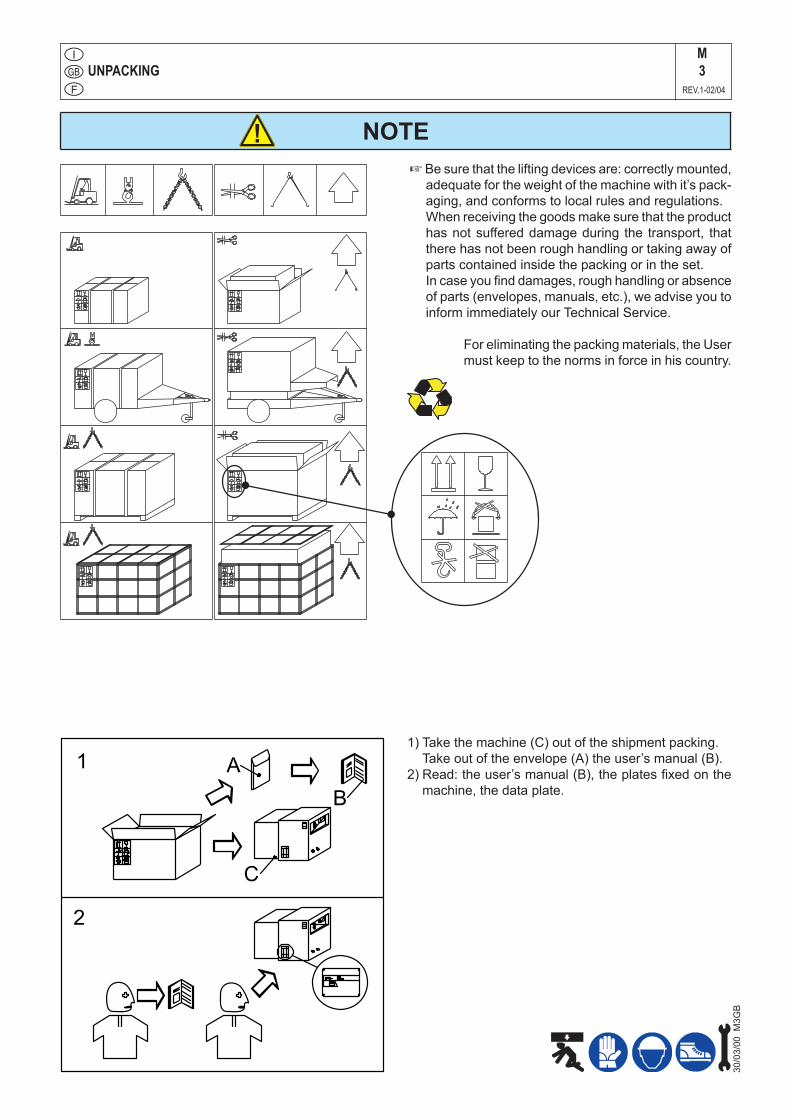
NOTE
UNPACKINGM3
REV.1-02/04
!+ Be sure that the lifting devices are: correctly mounted,
adequate for the weight of the machine with it’s pack-aging, and conforms to local rules and regulations.
When receiving the goods make sure that the product has not suffered damage during the transport, that there has not been rough handling or taking away of parts contained inside the packing or in the set.
In case you find damages, rough handling or absence of parts (envelopes, manuals, etc.), we advise you to inform immediately our Technical Service.
For eliminating the packing materials, the User must keep to the norms in force in his country.
1) Take the machine (C) out of the shipment packing. Take out of the envelope (A) the user’s manual (B).
2) Read: the user’s manual (B), the plates fixed on the machine, the data plate.
30/0
3/00
M3G
B
2
B
A1
C
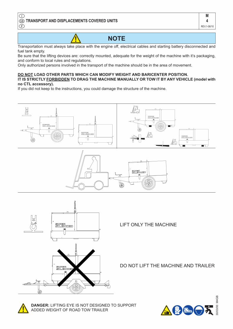
TRANSPORT AND DISPLACEMENTS COVERED UNITSM4
REV.1-06/10
NOTE!Transportation must always take place with the engine off, electrical cables and starting battery disconnected and fuel tank empty.Be sure that the lifting devices are: correctly mounted, adequate for the weight of the machine with it’s packaging, and conform to local rules and regulations.Only authorized persons involved in the transport of the machine should be in the area of movement.
DO NOT LOAD OTHER PARTS WHICH CAN MODIFY WEIGHT AND BARICENTER POSITION.IT IS STRICTLY FORBIDDEN TO DRAG THE MACHINE MANUALLY OR TOW IT BY ANY VEHICLE (model with no CTL accessory).If you did not keep to the instructions, you could damage the structure of the machine.
DANGER: LIFTING EYE IS NOT DESIGNED TO SUPPORTADDED WEIGHT OF ROAD TOW TRAILER
DO NOT LIFT THE MACHINE AND TRAILER
LIFT ONLY THE MACHINE
!
30/0
3/00
M4G
B
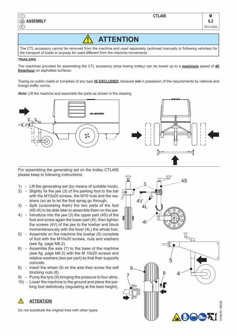
ASSEMBLYCTL400 M
6.2REV.0-06/00
Nota: Lift the machine and assemble the parts as shown in the drawing
For assembling the generating set on the trolley CTL400 please keep to following instructions:
1) - Lift the generating set (by means of suitable hook).2) - Slightly fix the jaw (3) of the parking foot to the bar
with the M10x20 screws, the M10 nuts and the wa-shers (so as to let the foot sprag go through.
3) - Split (unscrewing them) the two parts of the foot (4S-4I) to be able later to assemble them on the jaw.
4) - Introduce into the jaw (3) the upper part (4S) of the foot and screw again the lower part (4I), then tighten the screws (4V) of the jaw to the towbar and block momentaneously with the lever (4L) the whole foot.
5) - Assemble on the machine the towbar (5) complete of foot with the M10x20 screws, nuts and washers (see fig. page M6.2).
6) - Assemble the axle (7) to the base of the machine (see fig. page M6.2) with the M 10x20 screws and relative washers (two per part) so that their supports coincide.
8) - Insert the wheel (9) on the axle then screw the self blocking nuts (8).
9) - Pump the tyre (9) bringing the pressure to four atms.10) - Lower the machine to the ground and place the par-
king foot definitively (regulating at the best height).
ATTENTION
Do not substitute the original tires with other types.
!
4
5
34S
4I
4L
4V
78
9
TRAILERS
The machines provided for assembling the CTL accessory (slow towing trolley) can be towed up to a maximum speed of 40 Kms/hour on asphalted surfaces.
Towing on public roads or turnpikes of any type IS EXCLUDED, because not in possesion of the requirements by national and foreign traffic norms.
10/0
6/00
M6G
B
ATTENTIONThe CTL accessory cannot be removed from the machine and used separately (actioned manually or following vehicles) for the transport of loads or anyway for used different from the machine movements.
!
Set-up for operation (Engine diesel) Air cooled systemsM20
REV.1-09/05
16/0
7/03
M20
-R-A
-GB
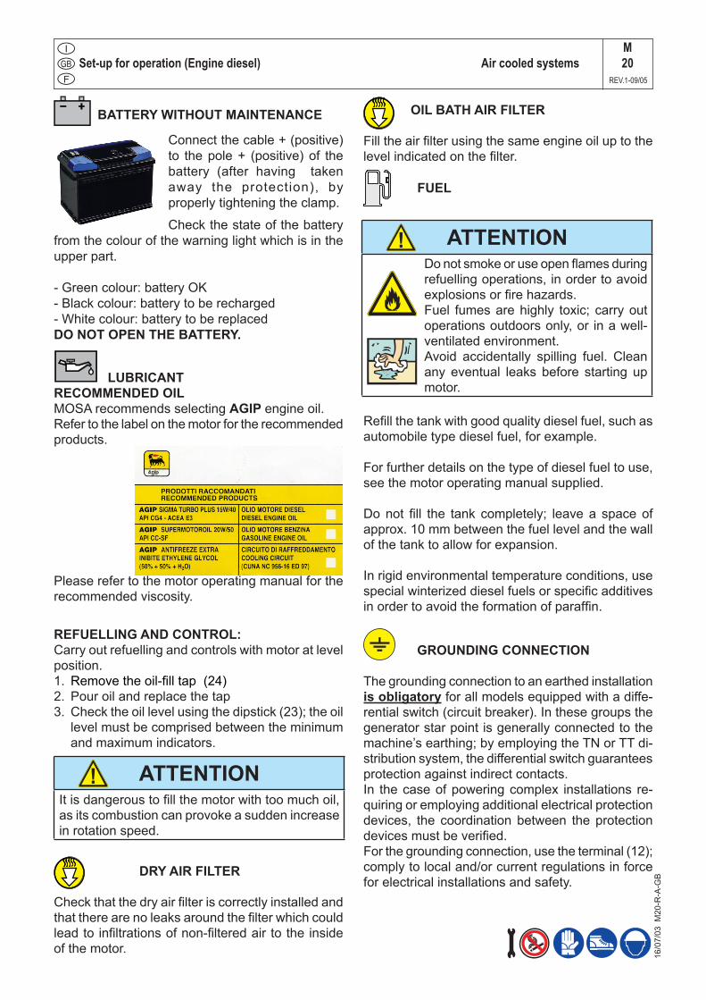
BATTERY WITHOUT MAINTENANCE
Connect the cable + (positive) to the pole + (positive) of the battery (after having taken away the protection), by properly tightening the clamp.
Check the state of the battery from the colour of the warning light which is in the upper part.
- Green colour: battery OK- Black colour: battery to be recharged- White colour: battery to be replacedDO NOT OPEN THE BATTERY.
LUBRICANTRECOMMENDED OILMOSA recommends selecting AGIP engine oil.Refer to the label on the motor for the recommended products.
Please refer to the motor operating manual for the recommended viscosity.
FUEL
Refill the tank with good quality diesel fuel, such as automobile type diesel fuel, for example.
For further details on the type of diesel fuel to use, see the motor operating manual supplied.
Do not fill the tank completely; leave a space of approx. 10 mm between the fuel level and the wall of the tank to allow for expansion.
In rigid environmental temperature conditions, use special winterized diesel fuels or specific additives in order to avoid the formation of paraffin.
GROUNDING CONNECTION
The grounding connection to an earthed installation is obligatory for all models equipped with a diffe-rential switch (circuit breaker). In these groups the generator star point is generally connected to the machine’s earthing; by employing the TN or TT di-stribution system, the differential switch guarantees protection against indirect contacts.In the case of powering complex installations re-quiring or employing additional electrical protection devices, the coordination between the protection devices must be verified.For the grounding connection, use the terminal (12); comply to local and/or current regulations in force for electrical installations and safety.
REFUELLING AND CONTROL:Carry out refuelling and controls with motor at level position.1. Remove the oil-fill tap (24)2. Pour oil and replace the tap3. Check the oil level using the dipstick (23); the oil
level must be comprised between the minimum and maximum indicators.
DRY AIR FILTER
Check that the dry air filter is correctly installed and that there are no leaks around the filter which could lead to infiltrations of non-filtered air to the inside of the motor.
OIL BATH AIR FILTER
Fill the air filter using the same engine oil up to the level indicated on the filter.
ATTENTIONDo not smoke or use open flames during refuelling operations, in order to avoid explosions or fire hazards.Fuel fumes are highly toxic; carry out operations outdoors only, or in a well-ventilated environment. Avoid accidentally spilling fuel. Clean any eventual leaks before starting up motor.
ATTENTIONIt is dangerous to fill the motor with too much oil, as its combustion can provoke a sudden increase in rotation speed.
!
!

NOTEDo not alter the primary conditions of regulation and do not touch the sealed parts.
NOTEFor safety reason the key must be kept by qualified personel.
CAUTIONRUNNING-INDuring the first 50 hours of operation, do not use more than 60% of the maximum output power of the unit and check the oil level frequently, in any case please stick to the rules given in the engine use manual.
CAUTIONMACHINE WITH EMERGENCY BUTTON
Pressing the button the engine will stop im-mediately in any working condition.
Turn clockwise to reset the button.
!
!
!
!
M21
REV.0-02/06
START AND STOP (EP6)
02/0
2/06
M21
_EP
6-G
B
The starting of the unit can be effected in 3 different modes:
1) Start with EP6 key (Engine Control) Put the “Local/Remote” selector on Local. Turn the
key on “ON”, the EP6 display shows, only on the machines with mounted glow plugs for 5 secs, the symbol “UUUU”, then the message “Sta” appears the engine can be started, for then turn the key on “start” and start the engine.
On the display the word “Sta” remains for about 20 sec then automatically disappears; the engine must be started within 20 secs, otherwise the EP6 blocks the starting and on the display the word “fail” appears. Turning the key on “OFF” the EP6 is reset and a new starting cycle can be fixed.
Stop: it is COMPULSORY to disconnect the load first,
then to stop the engine turn the key on “OFF”.
2) Remote starting with TCM35 Put the “Local/Remote” selector on Local. Con-
nect TCM35 to the plug on the front panel and put the switch on “0”.
Turn the key on ON in the EP6, wait for the various signals to go out then press the button “AUTO” in the EP6 until the led “AUTO” flashes.
Shift the switch on “I” in the TCM35 and automati-cally the starting cycle will start. On the machines with mounted glow plugs appears in the display EP6 (for about 5 secs), the symbol “UUUU“; the starting cycle includes 3 starting trials.
When the engine starts the led “AUTO” remains lit continuously and simultaneously the red warning light will light in the TCM35.
Stop: it is COMPULSORY to disconnect the load first,
then shift the switch of the TCM35 on “0”, the engine will stop immediately.
3) Start with Automatic start unit (EAS) Put the “Local/Remote” selector on Remote. Connect the EAS to unit.
The EAS controls the starting as well as the stop of the engine.
Follow attentively the instructions reported in the EAS manual. In these conditions the EP6 has the only function to measure the electric values, hour-meter, etc.
Check daily
CONTROLS LEGENDEM30
REV.2-07/08
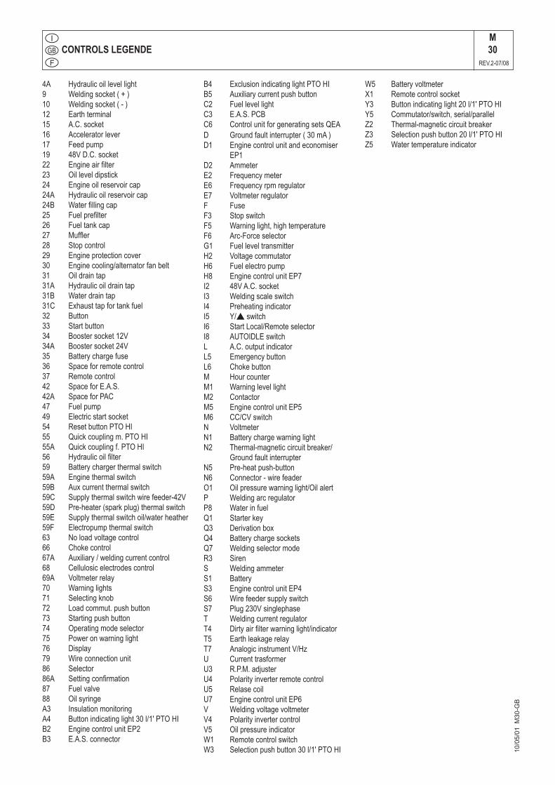
4A Hydraulicoillevellight9 Weldingsocket(+)10 Weldingsocket(-)12 Earthterminal15 A.C.socket16 Acceleratorlever17 Feedpump19 48VD.C.socket22 Engineairfilter23 Oilleveldipstick24 Engineoilreservoircap24A Hydraulicoilreservoircap24B Waterfillingcap25 Fuelprefilter26 Fueltankcap27 Muffler28 Stopcontrol29 Engineprotectioncover30 Enginecooling/alternatorfanbelt31 Oildraintap31A Hydraulicoildraintap31B Waterdraintap31C Exhausttapfortankfuel32 Button33 Startbutton34 Boostersocket12V34A Boostersocket24V35 Batterychargefuse36 Spaceforremotecontrol37 Remotecontrol42 SpaceforE.A.S.42A SpaceforPAC47 Fuelpump49 Electricstartsocket54 ResetbuttonPTOHI55 Quickcouplingm.PTOHI55A Quickcouplingf.PTOHI56 Hydraulicoilfilter59 Batterychargerthermalswitch59A Enginethermalswitch59B Auxcurrentthermalswitch59C Supplythermalswitchwirefeeder-42V59D Pre-heater(sparkplug)thermalswitch59E Supplythermalswitchoil/waterheather59F Electropumpthermalswitch63 Noloadvoltagecontrol66 Chokecontrol67A Auxiliary/weldingcurrentcontrol68 Cellulosicelectrodescontrol69A Voltmeterrelay70 Warninglights71 Selectingknob72 Loadcommut.pushbutton73 Startingpushbutton74 Operatingmodeselector75 Poweronwarninglight76 Display79 Wireconnectionunit86 Selector86A Settingconfirmation87 Fuelvalve88 OilsyringeA3 InsulationmonitoringA4 Buttonindicatinglight30l/1'PTOHIB2 EnginecontrolunitEP2B3 E.A.S.connector
B4 ExclusionindicatinglightPTOHIB5 AuxiliarycurrentpushbuttonC2 FuellevellightC3 E.A.S.PCBC6 ControlunitforgeneratingsetsQEAD Groundfaultinterrupter(30mA)D1 Enginecontrolunitandeconomiser
EP1D2 AmmeterE2 FrequencymeterE6 FrequencyrpmregulatorE7 VoltmeterregulatorF FuseF3 StopswitchF5 Warninglight,hightemperatureF6 Arc-ForceselectorG1 FuelleveltransmitterH2 VoltagecommutatorH6 FuelelectropumpH8 EnginecontrolunitEP7I2 48VA.C.socketI3 WeldingscaleswitchI4 PreheatingindicatorI5 Y/switchI6 StartLocal/RemoteselectorI8 AUTOIDLEswitchL A.C.outputindicatorL5 EmergencybuttonL6 ChokebuttonM HourcounterM1 WarninglevellightM2 ContactorM5 EnginecontrolunitEP5M6 CC/CVswitchN VoltmeterN1 BatterychargewarninglightN2 Thermal-magneticcircuitbreaker/
GroundfaultinterrupterN5 Pre-heatpush-buttonN6 Connector-wirefeaderO1 Oilpressurewarninglight/OilalertP WeldingarcregulatorP8 WaterinfuelQ1 StarterkeyQ3 DerivationboxQ4 BatterychargesocketsQ7 WeldingselectormodeR3 SirenS WeldingammeterS1 BatteryS3 EnginecontrolunitEP4S6 WirefeedersupplyswitchS7 Plug230VsinglephaseT WeldingcurrentregulatorT4 Dirtyairfilterwarninglight/indicatorT5 EarthleakagerelayT7 AnalogicinstrumentV/HzU CurrenttrasformerU3 R.P.M.adjusterU4 PolarityinverterremotecontrolU5 RelasecoilU7 EnginecontrolunitEP6V WeldingvoltagevoltmeterV4 PolarityinvertercontrolV5 OilpressureindicatorW1 RemotecontrolswitchW3 Selectionpushbutton30l/1'PTOHI 10
/05/
01 M
30-G
B
W5 BatteryvoltmeterX1 RemotecontrolsocketY3 Buttonindicatinglight20l/1'PTOHIY5 Commutator/switch,serial/parallelZ2 Thermal-magneticcircuitbreakerZ3 Selectionpushbutton20l/1'PTOHIZ5 Watertemperatureindicator
ComandiControlsCommandes
BedienelementeMandos GE 10 LSX
12/10
/10 3
4010
-I
M31
REV.1-10/12

Components of frontal panel GE 10 LSXM32
REV.0-10/10
12/10
/10 3
4010
-GB
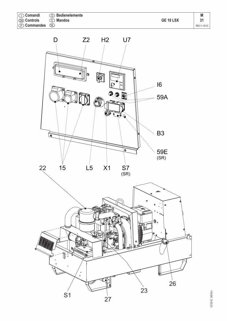
Z2 Thermal-magnetic circuit breaker General switch for the gen-set.It protects both gen-set and related electrical circuit from over current /short circuit.
D Ground fault interrupter ( 30 mA ) Device for protection against not-direct contacts for TN and TT systems (neutral grounded to frame)
12 Earth terminal Ground connection point for gen-set.15 A.C. socket AUX sockets for load connection.U7 Engine control unit EP6 Engine control unit.
Genset stop/ start.Handling of generator alarms.display of alarms, Voltage, Hz, hour counter, Amps, battery vol-tage, operation messages.
I6 Start Local/Remote selector Selection of engine control in use.Local start: control on board, EP6 operated.Remote start: external control, EAS operated.
H2 Voltage commutator Selection of visualized line voltage.59A Engine thermal switch Protection against over-currents and short circuits in the engine
electrical system.L5 Emergency button To be pushed in case of danger.
Immediate stop of the gen-set.X1 Remote control socket Connection for TCM35 remote control or for a NO clean contact,
both operating only if EP6 is set to AUTO.B3 E.A.S. connector Connection for automatic intervention unit (AMF + ATS).
16 pin connector.S7 (SR) Plug 230V singlephase External supply for engine heater (mains).
59E Supply thermal switch oil/water heather Protection against over-current & short circuit of the engine he-ater.
R3 Siren Gen-set acoustic alarm.E7 (SR) Voltage regulator / potentiometer Regulation of output voltage.
Using the generator
12/0
6/03
M37
GB
_150
0G_G
E
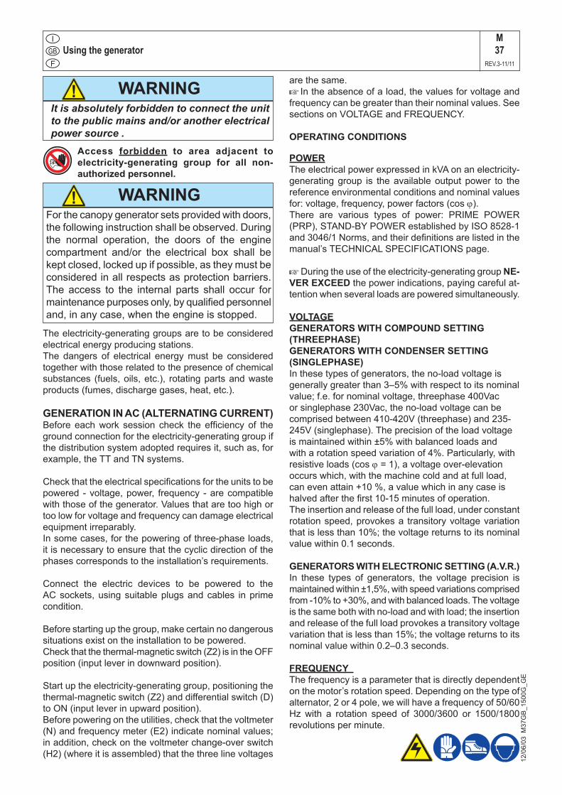
WARNING!
Access forbidden to area adjacent to electricity-generating group for all non-authorized personnel.
It is absolutely forbidden to connect the unit to the public mains and/or another electrical power source .
M 37
REV.3-11/11
The electricity-generating groups are to be considered electrical energy producing stations.The dangers of electrical energy must be considered together with those related to the presence of chemical substances (fuels, oils, etc.), rotating parts and waste products (fumes, discharge gases, heat, etc.).
GENERATION IN AC (ALTERNATING CURRENT)Before each work session check the efficiency of the ground connection for the electricity-generating group if the distribution system adopted requires it, such as, for example, the TT and TN systems.
Check that the electrical specifications for the units to be powered - voltage, power, frequency - are compatible with those of the generator. Values that are too high or too low for voltage and frequency can damage electrical equipment irreparably.In some cases, for the powering of three-phase loads, it is necessary to ensure that the cyclic direction of the phases corresponds to the installation’s requirements.
Connect the electric devices to be powered to the AC sockets, using suitable plugs and cables in prime condition.
Before starting up the group, make certain no dangerous situations exist on the installation to be powered.Check that the thermal-magnetic switch (Z2) is in the OFF position (input lever in downward position).
Start up the electricity-generating group, positioning the thermal-magnetic switch (Z2) and differential switch (D) to ON (input lever in upward position). Before powering on the utilities, check that the voltmeter (N) and frequency meter (E2) indicate nominal values; in addition, check on the voltmeter change-over switch (H2) (where it is assembled) that the three line voltages
are the same.+
In the absence of a load, the values for voltage and
frequency can be greater than their nominal values. See sections on VOLTAGE and FREQUENCY.
OPERATING CONDITIONS
POWERThe electrical power expressed in kVA on an electricity-generating group is the available output power to the reference environmental conditions and nominal values for: voltage, frequency, power factors (cos ϕ).There are various types of power: PRIME POWER (PRP), STAND-BY POWER established by ISO 8528-1 and 3046/1 Norms, and their definitions are listed in the manual’s TECHNICAL SPECIFICATIONS page.
+ During the use of the electricity-generating group NE-VER EXCEED the power indications, paying careful at-tention when several loads are powered simultaneously.
VOLTAGEGENERATORS WITH COMPOUND SETTING (THREEPHASE)GENERATORS WITH CONDENSER SETTING (SINGLEPHASE)In these types of generators, the no-load voltage is generally greater than 3–5% with respect to its nominal value; f.e. for nominal voltage, threephase 400Vac or singlephase 230Vac, the no-load voltage can be comprised between 410-420V (threephase) and 235-245V (singlephase). The precision of the load voltage is maintained within ±5% with balanced loads and with a rotation speed variation of 4%. Particularly, with resistive loads (cos ϕ = 1), a voltage over-elevation occurs which, with the machine cold and at full load, can even attain +10 %, a value which in any case is halved after the first 10-15 minutes of operation. The insertion and release of the full load, under constant rotation speed, provokes a transitory voltage variation that is less than 10%; the voltage returns to its nominal value within 0.1 seconds.
GENERATORS WITH ELECTRONIC SETTING (A.V.R.)In these types of generators, the voltage precision is maintained within ±1,5%, with speed variations comprised from -10% to +30%, and with balanced loads. The voltage is the same both with no-load and with load; the insertion and release of the full load provokes a transitory voltage variation that is less than 15%; the voltage returns to its nominal value within 0.2–0.3 seconds.
FREQUENCY The frequency is a parameter that is directly dependent on the motor’s rotation speed. Depending on the type of alternator, 2 or 4 pole, we will have a frequency of 50/60 Hz with a rotation speed of 3000/3600 or 1500/1800 revolutions per minute.
WARNING!For the canopy generator sets provided with doors, the following instruction shall be observed. During the normal operation, the doors of the engine compartment and/or the electrical box shall be kept closed, locked up if possible, as they must be considered in all respects as protection barriers. The access to the internal parts shall occur for maintenance purposes only, by qualified personnel and, in any case, when the engine is stopped.
Using the generator
The frequency, and therefore the number of motor revolutions, is maintained constant by the motor’s speed regulation system.Generally, this regulator is of a mechanical type and presents a droop from no-load to nominal load which is less than 5 % (static or droop), while under static conditions precision is maintained within ±1%.Therefore, for generators at 50Hz the no-load frequency can be 52–52.5 Hz, while for generators at 60Hz the no-load frequency can be 62.5-63Hz.In some motors or for special requirements the speed regulator is electronic; in these cases, precision under static operating conditions attains ±0.25%, and the frequency is maintained constant in operation from no-load to load (isochronal operation).
POWER FACTOR - COS ϕThe power factor is a value which depends on the load’s electrical specifications; it indicates the ratio between the Active Power (kW) and Apparent Power (kVA). The apparent power is the total power necessary for the load, achieved from the sum of the active power supplied by the motor (after the alternator has transformed the mechanical power into electrical power), and the Reactive Power (kVAR) supplied by the alternator. The nominal value for the power factor is cos ϕ = 0,8; for different values comprised between 0.8 and 1 it is important during usage not to exceed the declared active power (kW), so as to not overload the electricity-generating group motor; the apparent power (kVA) will diminish proportionally to the increase of cos ϕ.For cos ϕ values of less than 0.8 the alternator must be downgraded, since at equal apparent power the alternator should supply a greater reactive power. For reduction coefficients, contact the Technical Service Department.
START-UP OF ASYNCHRONOUS MOTORSThe start-up of asynchronous motors from an electricity-generating group can prove critical because of high start-up currents the asynchronous motor requires (I start-up = up to 8 times the nominal current In.). The start-up current must not exceed the alternator’s admissible overload current for brief periods, generally in the order of 250–300% for 10–15 seconds.To avoid a group oversize, we recommend following these precautionary measures:- in the case of a start-up of several motors, subdivide the
motors into groups and set up their start-up at intervals of 30–60 seconds.
- when the operating machine coupled to the motor allows it, see to a start-up with reduced voltage, star point/triangle start-up or with autotransformer, or use a soft-start system.
In all cases, when the user circuit requires the start-up of an asynchronous motor, it is necessary to check that there are no utilities inserted into the installation, which in the case of a voltage droop can cause more or less serious disservices (opening of contact points, temporary lack of power to control and command systems, etc.).
12/0
6/03
M37
GB
_150
0G_G
E
SINGLE-PHASE LOADS Power to monophase utilities by means of three-phase generators requires some operating limitations.- In single-phase operation, the declared voltage
tolerance can no longer be maintained by the regulator (compound or electronic regulator), since the system becomes highly unbalanced. The voltage variation on the phases not affected by the power can prove dangerous; we recommend sectioning the other loads eventually connected.
- The maximum power which can be drawn between Neutral and Phase (start connection) is generally 1/3 of the nominal three-phase power; some types of alternators even allow for 40%. Between two Phases (triangle connection) the maximum power cannot exceed 2/3 of the declared three-phase power.
- In electricity-generating groups equipped with monophase sockets, use these sockets for connecting the loads. In other cases, always use the "R" phase and Neutral.
ELECTRIC PROTECTIONS
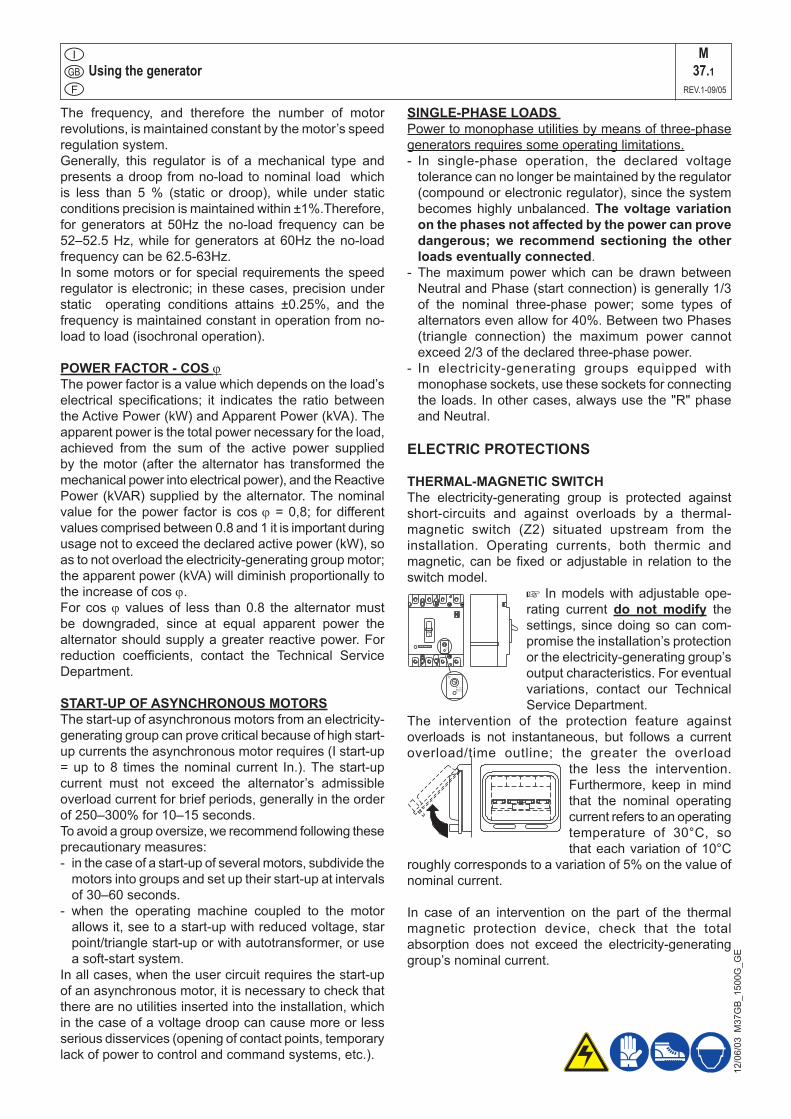
THERMAL-MAGNETIC SWITCHThe electricity-generating group is protected against short-circuits and against overloads by a thermal-magnetic switch (Z2) situated upstream from the installation. Operating currents, both thermic and magnetic, can be fixed or adjustable in relation to the switch model.
+ In models with adjustable ope-rating current do not modify the settings, since doing so can com-promise the installation’s protection or the electricity-generating group’s output characteristics. For eventual variations, contact our Technical Service Department.
The intervention of the protection feature against overloads is not instantaneous, but follows a current overload/time outline; the greater the overload
the less the intervention. Furthermore, keep in mind that the nominal operating current refers to an operating temperature of 30°C, so that each variation of 10°C
roughly corresponds to a variation of 5% on the value of nominal current.
In case of an intervention on the part of the thermal magnetic protection device, check that the total absorption does not exceed the electricity-generating group’s nominal current.
M37.1
REV.1-09/05
Using the generator
12/0
6/03
M37
GB
_150
0G_G
E
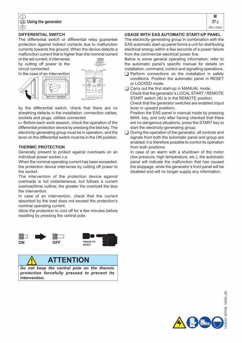
DIFFERENTIAL SWITCHThe differential switch or differential relay guarantee protection against indirect contacts due to malfunction currents towards the ground. When the device detects a malfunction current that is higher than the nominal current or the set current, it intervenes by cutting off power to the circuit connected. In the case of an intervention
by the differential switch, check that there are no sheathing defects in the installation: connection cables, sockets and plugs, utilities connected.+ Before each work session, check the operation of the differential protection device by pressing the test key. The electricity-generating group must be in operation, and the lever on the differential switch must be in the ON position.
THERMIC PROTECTIONGenerally present to protect against overloads on an individual power socket c.a. When the nominal operating current has been exceeded, the protection device intervenes by cutting off power to the socket. The intervention of the protection device against overloads is not instantaneous, but follows a current overload/time outline; the greater the overload the less the intervention.In case of an intervention, check that the current absorbed by the load does not exceed the protection’s nominal operating current.Allow the protection to cool off for a few minutes before resetting by pressing the central pole.
ON OFF PRESS TORESET
Do not keep the central pole on the thermic protection forcefully pressed to prevent its intervention.
ATTENTION!
USAGE WITH EAS AUTOMATIC START-UP PANELThe electricity-generating group in combination with the EAS automatic start-up panel forms a unit for distributing electrical energy within a few seconds of a power failure from the commercial electrical power line.Below is some general operating information; refer to the automatic panel’s specific manual for details on installation, command, control and signalling operations. Perform connections on the installation in safety
conditions. Position the automatic panel in RESET or LOCKED mode.
Carry out the first start-up in MANUAL mode. Check that the generator’s LOCAL START / REMOTE
START switch (I6) is in the REMOTE position. Check that the generator switches are enabled (input
lever in upward position). Position the EAS panel in manual mode by pressing
MAN. key, and only after having checked that there are no dangerous situations, press the START key to start the electricity-generating group.
During the operation of the generator, all controls and signals from both the automatic panel and group are enabled; it is therefore possible to control its operation from both positions.
In case of an alarm with a shutdown of the motor (low pressure, high temperature, etc.), the automatic panel will indicate the malfunction that has caused the stoppage, while the generator’s front panel will be disabled and will no longer supply any information.
T5.4
T5.1
T5.3
T5.2
T5.10
T5.6 T5.7
T5.8
T5.9
TRIPON
TESTRESET
0.25 2.5
20.5
1.51
0.02
0.1
0.2
0.5
0.3
0.4
RESET
I° (A) t (s)
RESETA M
tx10 tx1x1x10
x0.1I°I°
x10
tx10x1
I°
Mtx1
x0.1I°
A
1 c 0
1 d 0
1 b 0
1 a 0
T5.5
M37.2
REV.1-09/05
TCM 35 REMOTE CONTROLM
38.6REV.0-03/06
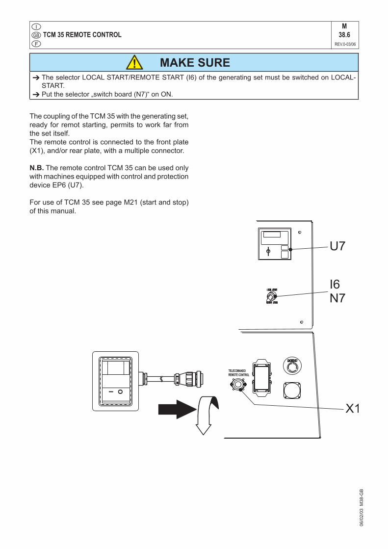
The coupling of the TCM 35 with the generating set, ready for remot starting, permits to work far from the set itself.The remote control is connected to the front plate (X1), and/or rear plate, with a multiple connector.
N.B. The remote control TCM 35 can be used only with machines equipped with control and protection device EP6 (U7).
For use of TCM 35 see page M21 (start and stop) of this manual.
06/0
2/03
M38
-GB
MAKE SURE The selector LOCAL START/REMOTE START (I6) of the generating set must be switched on LOCAL-
START. Put the selector „switch board (N7)“ on ON.
!

PROTECTIONS EP6 ENGINE PROTECTIONM
39.12REV.1-03/11
12/1
0/05
M39
GB
FRONT PANEL
1.0 INTRODUCTIONThe EP6 features Engine and Generating Set control and monitoring. The EP6 provides visual indication by means of LEDs (solid state lamps) and a Display (see section 10.0). It features OFF, MAN and AUTO operating modes. The display gives Messages for alarms and Measurement indications.
EP6 has programmable parameters. Please con-tact the producer of the generating set to receive instructions related to programming.
2.0 OPERATING MODE selectionThe EP6 features AUTO (section 2.1), MANUAL (section 2.2) and OFF (section 2.3) operating modes. When the power supply is switched on, the EP6 behaves as follow:A) if the KEY-SWITCH is in the OFF position, the
EP6 enters the OFF operating mode. B) if the KEY-SWITCH is in the ON position, the EP6
enters the AUTO operating mode. That is, if the EP6 was in AUTO prior to the supply removal. If not, the EP6 enters the MANUAL operating mode.
2.1 AUTO operating modeTo enter the "AUTO" operating mode use the follow-ing instructions:A) - Turn ON the key switch: the Display and LEDs
illuminate for 1 second.B) - Wait for the end of the LAMP test, then push the
AUTO pushbutton after the [UUUU] (Pre-glow) or [Sta-] (Start prompt) has been displayed. Af-ter this, the yellow Led AUTO will illuminate. If the REMOTE START input is not operative, the LED will flash. If operative, the LED illuminates continuously and a start cycle will take place (NOTE: the EP6 shuts down the display during the crank).
C) - In order to cancel the AUTO operating mode, push the AUTO pushbutton (the yellow Led will turn OFF) or turn the KEY-SWITCH to OFF.
Once in AUTO, the EP6 waits for a REMOTE START activation (see section 7.0).
In case of an Automatic Periodic Test (A.P.T.), the display will show the message [tESt].
2.2 MANUAL operating mode To start the engine follow the instructions:A) - Turn ON the KEY-SWITCH; the EP6 illuminates
the LEDs and Display.B) - If the display shows the message [uuuu], the EP6
is counting the PRE-GLOW time; wait until the message disappears.
C) - After the display shows the flashing message [StA-] (NOTE), turn the Key to START position (momentary position with spring-loaded return) until the engine starts. The message [ . . . .] in-dicates a MANUAL start.
D) - To stop the engine, turn the KEY SWITCH to OFF.
NOTE: EP6 shows the blinking [StA-] message for 20 seconds. After this time, if the engine does not start, the EP6 displays the message [FAIL] (Fail to start, see section 4.07).To clear the alarm, turn the KEY-SWITCH to OFF.
2.3 OFF operating mode This function is obtained by turning the KEY SWITCH to OFF. The OFF operating mode clears the fault alarms and shuts down the Display after 5 seconds. A blinking dot indicates the presence of the power supply. Press one of the pushbuttons to energize the display. In OFF operating mode, the EP6 allows reading of the parameters (see section 6.0). 3.0 DISPLAY featuresThe EP6 features a 4 Digit Display (section10.0) to show measurements, settings and error messages. The [UP-DOWN] pushbutton selects one of the fol-lowing menus:
[AXXX] (*) Generator Current measurement [UXXX] The Voltage of the Generating Set [rPM] [XXXX] Speed of the engine [HXX.X] Frequency of the Generator[bXX.X] Battery Voltage[cXX.X] Charger Alternator Voltage [ h ] [XXXX] HOUR METER (the message [h] ap-pears for a moment, and then, the counter will be displayed continuously).
(*): the symbol "X" means a numerical field.
4 digits DISPLAY
Ideograms
Button[F1]
Button[ENTER] (*)
Key(OFF-ON-START)
Button [+](*)
Button [-] (*)
Button[AUTO]
AUTO (YellowLed)
[UP DOWN]Button
Green LED engine on
(*) The use of these buttons is reserved only to the manufacturer of the generating set.
PROTECTIONS EP6 ENGINE PROTECTIONM
39.12.1REV.1-03/11
12/1
0/05
M39
GB
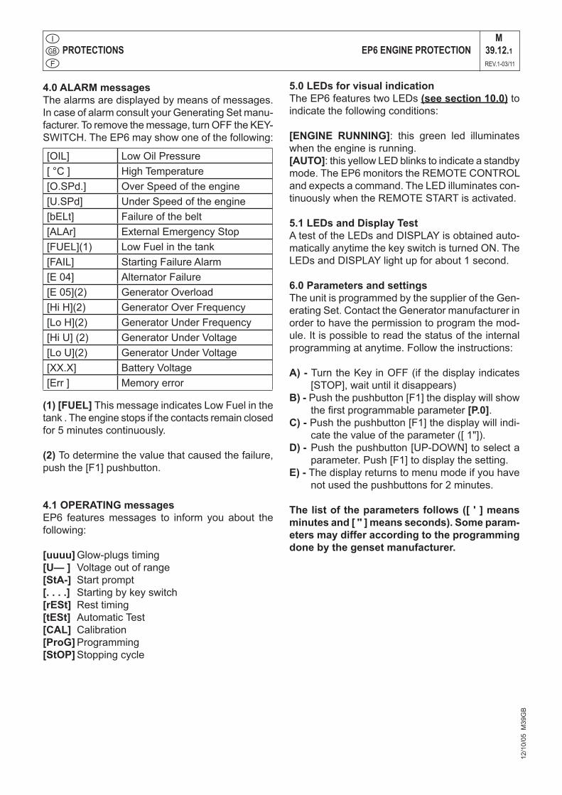
4.0 ALARM messagesThe alarms are displayed by means of messages. In case of alarm consult your Generating Set manu-facturer. To remove the message, turn OFF the KEY-SWITCH. The EP6 may show one of the following:
(1) [FUEL] This message indicates Low Fuel in the tank . The engine stops if the contacts remain closed for 5 minutes continuously.
(2) To determine the value that caused the failure, push the [F1] pushbutton.
4.1 OPERATING messagesEP6 features messages to inform you about the following:
[uuuu] Glow-plugs timing[U— ] Voltage out of range[StA-] Start prompt[. . . .] Starting by key switch[rESt] Rest timing[tESt] Automatic Test[CAL] Calibration[ProG] Programming[StOP] Stopping cycle
5.0 LEDs for visual indicationThe EP6 features two LEDs (see section 10.0) to indicate the following conditions:
[ENGINE RUNNING]: this green led illuminates when the engine is running.[AUTO]: this yellow LED blinks to indicate a standby mode. The EP6 monitors the REMOTE CONTROL and expects a command. The LED illuminates con-tinuously when the REMOTE START is activated.
5.1 LEDs and Display Test A test of the LEDs and DISPLAY is obtained auto-matically anytime the key switch is turned ON. The LEDs and DISPLAY light up for about 1 second.
6.0 Parameters and settings The unit is programmed by the supplier of the Gen-erating Set. Contact the Generator manufacturer in order to have the permission to program the mod-ule. It is possible to read the status of the internal programming at anytime. Follow the instructions:
A) - Turn the Key in OFF (if the display indicates [STOP], wait until it disappears)
B) - Push the pushbutton [F1] the display will show the first programmable parameter [P.0].
C) - Push the pushbutton [F1] the display will indi-cate the value of the parameter ([ 1"]).
D) - Push the pushbutton [UP-DOWN] to select a parameter. Push [F1] to display the setting.
E) - The display returns to menu mode if you have not used the pushbuttons for 2 minutes.
The list of the parameters follows ([ ' ] means minutes and [ '' ] means seconds). Some param-eters may differ according to the programming done by the genset manufacturer.
[OIL] Low Oil Pressure[ °C ] High Temperature [O.SPd.] Over Speed of the engine[U.SPd] Under Speed of the engine[bELt] Failure of the belt[ALAr] External Emergency Stop [FUEL](1) Low Fuel in the tank[FAIL] Starting Failure Alarm[E 04] Alternator Failure[E 05](2) Generator Overload[Hi H](2) Generator Over Frequency[Lo H](2) Generator Under Frequency[Hi U] (2) Generator Under Voltage[Lo U](2) Generator Under Voltage[XX.X] Battery Voltage[Err ] Memory error
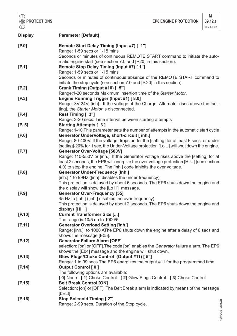
Display Parameter [Default]
[P.0] Remote Start Delay Timing (Input #7) [ 1"] Range: 1-59 secs or 1-15 mins Seconds or minutes of continuous REMOTE START command to initiate the auto-
matic engine start (see section 7.0 and [P20] in this section).[P.1] Remote Stop Delay Timing (Input #7) [ 1"] Range: 1-59 secs or 1-15 mins Seconds or minutes of continuous absence of the REMOTE START command to
initiate the stop cycle (see section 7.0 and [P.20] in this section).[P.2] Crank Timing (Output #10) [ 5"] Range:1-20 seconds Maximum insertion time of the Starter Motor. [P.3] Engine Running Trigger (Input #1) [ 8.0] Range: 3V-24V, [inh]. If the voltage of the Charger Alternator rises above the [set-
ting], the Starter Motor is disconnected.[P.4] Rest Timing [ 3"] Range: 3-20 secs. Time interval between starting attempts[P. 5] Starting Attempts [ 3 ] Range: 1-10 This parameter sets the number of attempts in the automatic start cycle[P.6] Generator UnderVoltage, short-circuit [ inh.] Range: 80-400V. If the voltage drops under the [setting] for at least 6 secs, or under
[setting]-20% for 1 sec, the Under-Voltage protection [Lo U] will shut down the engine.[P.7] Generator Over-Voltage [500V] Range: 110-550V or [inh.]. If the Generator voltage rises above the [setting] for at
least 2 seconds, the EP6 will energize the over voltage protection [Hi U] (see section 4.0) to stop the engine. The [inh.] code inhibits the over voltage.
[P.8] Generator Under-Frequency [Inh.] [inh.] 1 to 99Hz ([inh]=disables the under frequency) This protection is delayed by about 6 seconds. The EP6 shuts down the engine and
the display will show the [Lo H] message. [P.9] Generator Over-Frequency [55] 45 Hz to [inh.] ([inh.] disables the over frequency) This protection is delayed by about 2 seconds. The EP6 shuts down the engine and
displays [Hi H][P.10] Current Transformer Size [...] The range is 10/5 up to 1000/5[P.11] Generator Overload Setting [inh.] Range: [inh.] to 1000 AThe EP6 shuts down the engine after a delay of 6 secs and
shows the message [E05].[P.12] Generator Failure Alarm [OFF] selection: [on] or [OFF].The code [on] enables the Generator failure alarm. The EP6
shows the [E04] message and the engine will shut down.[P.13] Glow Plugs/Choke Control (Output #11) [ 5"] Range: 1 to 99 secs.The EP6 energizes the output #11 for the programmed time.[P.14] Output Control [ 0 ] The following options are available: [ 0] None - [ 1] Choke Control - [ 2] Glow Plugs Control - [ 3] Choke Control [P.15] Belt Break Control [ON] Selection: [on] or [OFF]. The Belt Break alarm is indicated by means of the message
[bELt][P.16] Stop Solenoid Timing [ 2"] Range: 2-99 secs. Duration of the Stop cycle.
PROTECTIONS EP6 ENGINE PROTECTIONM
39.12.2REV.0-10/05
12/1
0/05
M39
GB
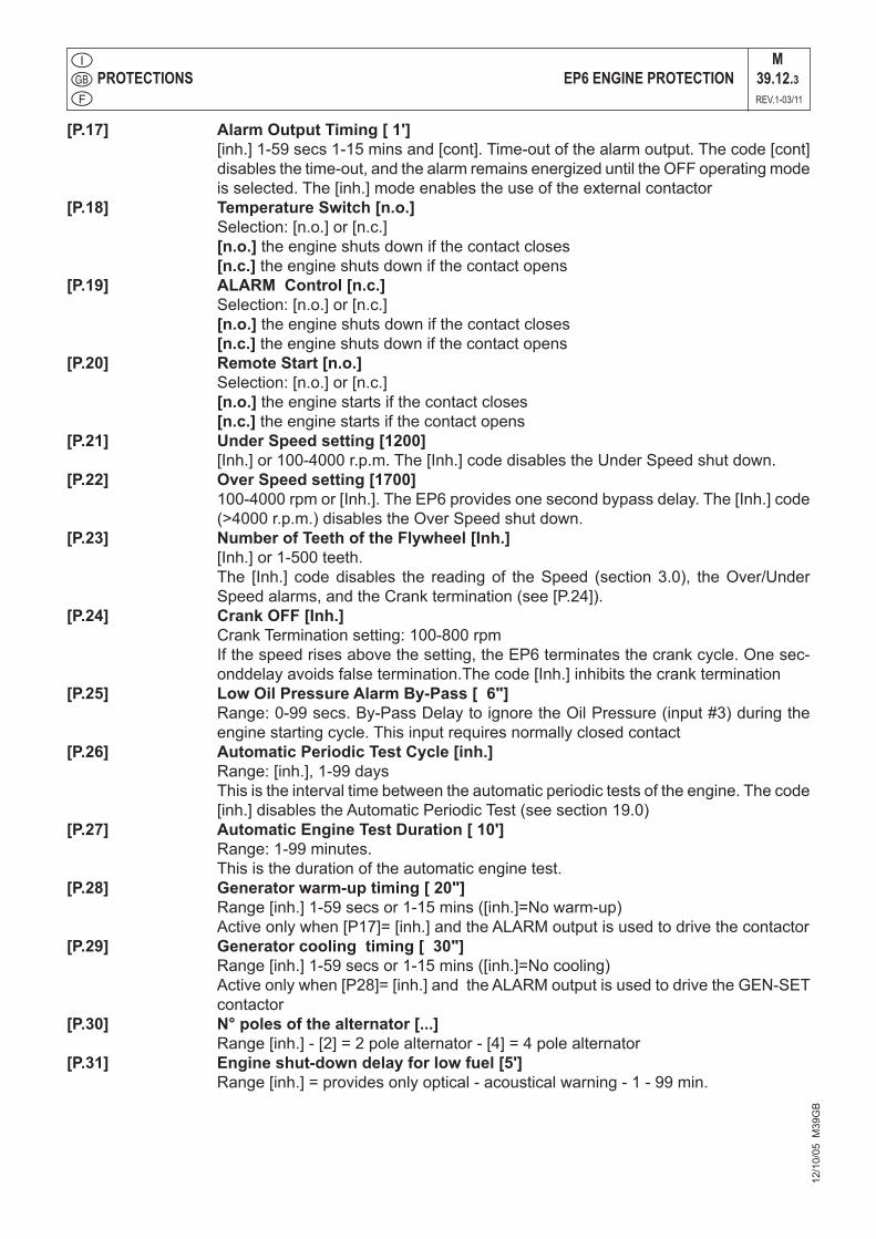
[P.17] Alarm Output Timing [ 1'] [inh.] 1-59 secs 1-15 mins and [cont]. Time-out of the alarm output. The code [cont]
disables the time-out, and the alarm remains energized until the OFF operating mode is selected. The [inh.] mode enables the use of the external contactor
[P.18] Temperature Switch [n.o.] Selection: [n.o.] or [n.c.] [n.o.] the engine shuts down if the contact closes [n.c.] the engine shuts down if the contact opens[P.19] ALARM Control [n.c.] Selection: [n.o.] or [n.c.] [n.o.] the engine shuts down if the contact closes [n.c.] the engine shuts down if the contact opens[P.20] Remote Start [n.o.] Selection: [n.o.] or [n.c.] [n.o.] the engine starts if the contact closes [n.c.] the engine starts if the contact opens[P.21] Under Speed setting [1200] [Inh.] or 100-4000 r.p.m. The [Inh.] code disables the Under Speed shut down.[P.22] Over Speed setting [1700] 100-4000 rpm or [Inh.]. The EP6 provides one second bypass delay. The [Inh.] code
(>4000 r.p.m.) disables the Over Speed shut down.[P.23] Number of Teeth of the Flywheel [Inh.] [Inh.] or 1-500 teeth. The [Inh.] code disables the reading of the Speed (section 3.0), the Over/Under
Speed alarms, and the Crank termination (see [P.24]).[P.24] Crank OFF [Inh.] Crank Termination setting: 100-800 rpm If the speed rises above the setting, the EP6 terminates the crank cycle. One sec-
onddelay avoids false termination.The code [Inh.] inhibits the crank termination[P.25] Low Oil Pressure Alarm By-Pass [ 6"] Range: 0-99 secs. By-Pass Delay to ignore the Oil Pressure (input #3) during the
engine starting cycle. This input requires normally closed contact[P.26] Automatic Periodic Test Cycle [inh.] Range: [inh.], 1-99 days This is the interval time between the automatic periodic tests of the engine. The code
[inh.] disables the Automatic Periodic Test (see section 19.0)[P.27] Automatic Engine Test Duration [ 10'] Range: 1-99 minutes. This is the duration of the automatic engine test.[P.28] Generator warm-up timing [ 20"] Range [inh.] 1-59 secs or 1-15 mins ([inh.]=No warm-up) Active only when [P17]= [inh.] and the ALARM output is used to drive the contactor[P.29] Generator cooling timing [ 30"] Range [inh.] 1-59 secs or 1-15 mins ([inh.]=No cooling) Active only when [P28]= [inh.] and the ALARM output is used to drive the GEN-SET
contactor[P.30] N° poles of the alternator [...] Range [inh.] - [2] = 2 pole alternator - [4] = 4 pole alternator[P.31] Engine shut-down delay for low fuel [5'] Range [inh.] = provides only optical - acoustical warning - 1 - 99 min.
PROTECTIONS EP6 ENGINE PROTECTIONM
39.12.3REV.1-03/11
12/1
0/05
M39
GB

7.0 REMOTE STARTThe EP6 features REMOTE START only in AUTO operating mode. To operate the REMOTE START, follow the instruc-tions.
A) - Turn the KEY-SWITCH to the ON position; the Display and LEDs illuminate for 1 sec.
B) - Wait until the end of the LEDs test.C) - Push the AUTO pushbutton as soon as possible
(otherwise, after 20 seconds the EP6 enters the STARTING FAILURE); the [AUTO] yellow LED will illuminate as described in the section 4.
REMOTE START SWITCH:If the REMOTE START input is activated, the [AUTO] yellow LED illuminates continuously and the display will indicate the count down of the internal start delay timer. The engine will start after the pro-grammed start delay time. If the REMOTE START is deactivated, the EP6 drives the stop delay time. The display will indicate the count down and the [AUTO] yellow LED will flash. The engine will stop after the programmed stop delay time.
8.0 SAFETY
9.0 Automatic periodic TEST
The EP6 does not use a clock to count the pro-grammed days ([P.26] setting, section 6.0). The maximum error and drift of the counter is +/-0,5%. The user may experiment with shifting the periodic tests. To avoid error accumulation, and in case your unit is programmed to allow Automatic Periodic Test, we recommend the following procedures.- disconnect the power supply of the EP6 (consult your genset supplier)
- wait for the desired start time (external clock ref-erence)
- apply the power supply to the EP6 (consult your genset supplier)
- select the "AUTO" operating mode
High voltage is present inside the EP6. To avoid electric-shock hazard, operating personnel must not remove the protective cover. Do not discon-nect the grounding connection. Any interruption of the grounding connection can create an electric shock hazard. Before making external connec-tions, always ground the PANEL first by connect-ing the control panel to ground.
NOTE!
The EP6 will start the engine after the programmed number of days and the engine will run for the pro-grammed time. To determine how the Automatic Periodic Test is programmed enter the Reading Mode (section 6.0 parameter [P.26] and [P.27]).
IMPORTANT NOTES If the supply (battery voltage) is removed, the EP6 loses the counts and timings. If the sup-ply restores, the EP6 starts to count the A.P.T. according to the programmed parameters [P.26] and [P.27]. It is important to synchronize the power on sequence with the desired Automatic Periodic Test.
PROTECTIONS EP6 ENGINE PROTECTIONM
39.12.4REV.1-03/11
12/1
0/05
M39
GB
Troubleshooting Diesel engine
28/0
1/03
M40
I_15
00G
_GE
M40.2
REV.3-07/06
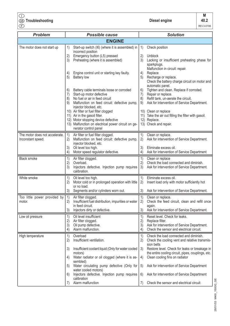
Problem Possible cause SolutionENGINE
The motor does not start up 1) Start-up switch (I6) (where it is assembled) in incorrect position
2) Emergency button (L5) pressed3) Preheating (where it is assembled)
4) Engine control unit or starting key faulty. 5) Battery low
6) Battery cable terminals loose or corroded7) Start-up motor defective8) No fuel or air in feed circuit9) Malfunction on feed circuit: defective pump,
injector blocked, etc.10) Air filter or fuel filter clogged11) Air in the gasoil filter. 12) Motor stopping device defective13) Malfunction on electrical power circuit on ge-
nerator control panel
1) Check position
2) Unblock3) Lacking or insufficient preheating phase for
sparkplugs. Malfunction in circuit: repair.4) Replace5) Recharge or replace. Check the battery charge circuit on motor and
automatic panel.6) Tighten and clean. Replace if corroded.7) Repair or replace.8) Refill tank, un-aerate the circuit.9) Ask for intervention of Service Department.
10) Clean or replace11) Take the air out filling the filter with gasoil.12) Replace.13) Check and repair.
The motor does not accelerate. Inconstant speed.
1) Air filter or fuel filter clogged.2) Malfunction on feed circuit: defective pump,
injector blocked, etc.3) Oil level too high.4) Motor speed regulator defective.
1) Clean or replace.2) Ask for intervention of Service Department.
3) Eliminate excess oil.4) Ask for intervention of Service Department
Black smoke 1) Air filter clogged.2) Overload.3) Injectors defective. Injection pump requires
calibration.
1) Clean or replace2) Check the load connected and diminish.3) Ask for intervention of Service Department.
White smoke 1) Oil level too high.2) Motor cold or in prolonged operation with little
or no load.3) Segments and/or cylinders worn out.
1) Eliminate excess oil.2) Insert load only with motor sufficiently hot
3) Ask for intervention of Service Department.Too little power provided by motor.
1) Air filter clogged.2) Insufficient fuel distribution, impurities or water
in feed circuit.3) Injectors dirty or defective.
1) Clean or replace.2) Check the feed circuit, clean and refill once
again.3) Ask for intervention of Service Department.
Low oil pressure 1) Oil level insufficient2) Air filter clogged.3) Oil pump defective.4) Alarm malfunction.
1) Reset level. Check for leaks.2) Replace filter.3) Ask for intervention of Service Department.4) Check the sensor and electrical circuit.
High temperature 1) Overload2) Insufficient ventilation.
3) Insufficient coolant liquid (Only for water cooled motors)
4) Water radiator or oil clogged (where it is as-sembled)
5) Water circulating pump defective (Only for water cooled motors)
6) Injectors defective. Injection pump requires calibration
7) Alarm malfunction
1) Check the load connected and diminish.2) Check the cooling vent and relative transmis-
sion belts3) Restore level. Check for leaks or breakage in
the entire cooling circuit, pipes, couplings, etc.4) Clean cooling fins on radiator
5) Ask for intervention of Service Department
6) Ask for intervention of Service Department
7) Check the sensor and electrical circuit
Troubleshooting Diesel engine
12/0
6/03
M40
GB
_150
0G_G
E
M40.2.1
REV.4-03/11
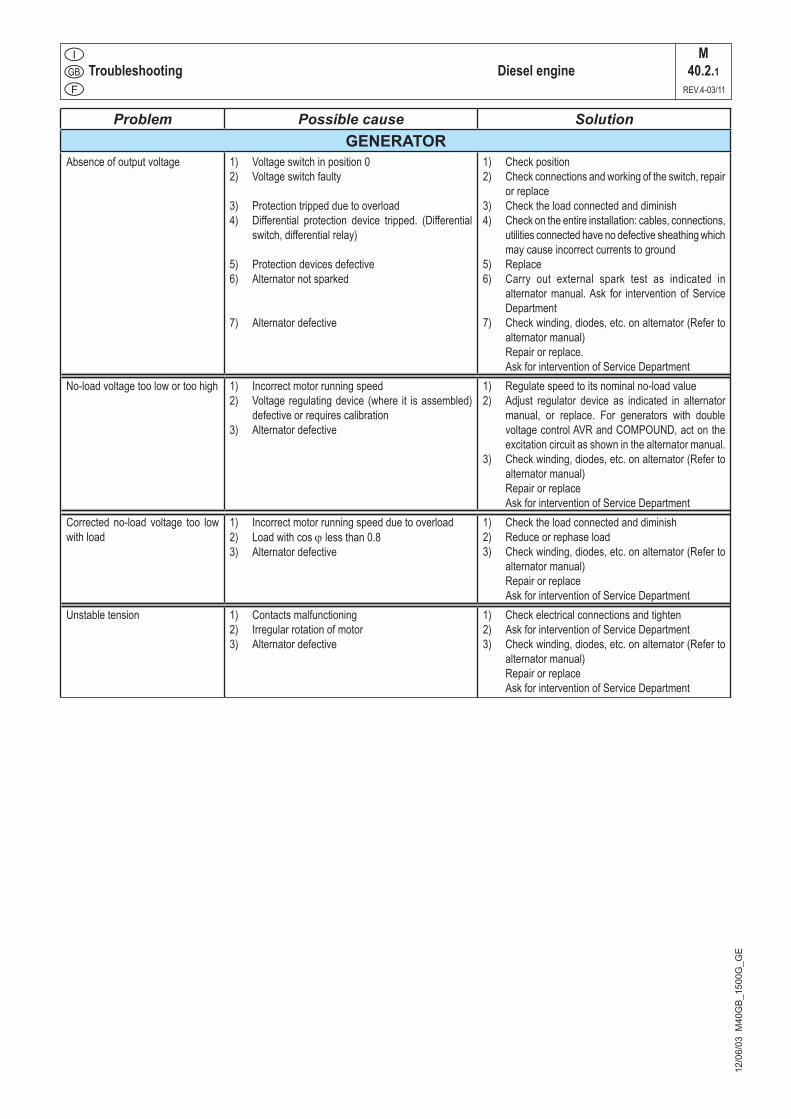
Problem Possible cause SolutionGENERATOR
Absence of output voltage 1) Voltage switch in position 02) Voltage switch faulty
3) Protection tripped due to overload4) Differential protection device tripped. (Differential
switch, differential relay)
5) Protection devices defective6) Alternator not sparked
7) Alternator defective
1) Check position2) Check connections and working of the switch, repair
or replace3) Check the load connected and diminish4) Check on the entire installation: cables, connections,
utilities connected have no defective sheathing which may cause incorrect currents to ground
5) Replace6) Carry out external spark test as indicated in
alternator manual. Ask for intervention of Service Department
7) Check winding, diodes, etc. on alternator (Refer to alternator manual)
Repair or replace. Ask for intervention of Service Department
No-load voltage too low or too high 1) Incorrect motor running speed2) Voltage regulating device (where it is assembled)
defective or requires calibration3) Alternator defective
1) Regulate speed to its nominal no-load value2) Adjust regulator device as indicated in alternator
manual, or replace. For generators with double voltage control AVR and COMPOUND, act on the excitation circuit as shown in the alternator manual.
3) Check winding, diodes, etc. on alternator (Refer to alternator manual)
Repair or replace Ask for intervention of Service Department
Corrected no-load voltage too low with load
1) Incorrect motor running speed due to overload2) Load with cos j less than 0.83) Alternator defective
1) Check the load connected and diminish2) Reduce or rephase load3) Check winding, diodes, etc. on alternator (Refer to
alternator manual) Repair or replace Ask for intervention of Service Department
Unstable tension 1) Contacts malfunctioning2) Irregular rotation of motor3) Alternator defective
1) Check electrical connections and tighten2) Ask for intervention of Service Department3) Check winding, diodes, etc. on alternator (Refer to
alternator manual) Repair or replace Ask for intervention of Service Department

MAINTENANCEM43
REV.0-06/10
05/0
9/05
M43
GB
NOTE
By maintenance at care of the utilizer we intend all the operatios concerning the verification of mechanical parts, electrical parts and of the fluids subject to use or consumption during the normal operation of the machine.
For what concerns the fluids we must consider as main-tenance even the periodical change and or the refills eventually necessary.
Maintenance operations also include machine cleaning operations when carried out on a periodic basis outside of the normal work cycle.
The repairs cannot be considered among the mainte-nance activities, i.e. the replacement of parts subject to occasional damages and the replacement of electric and mechanic components consumed in normal use, by the Assistance Authorized Center as well as by manufacturer.
The replacement of tires (for machines equipped with trolleys) must be considered as repair since it is not de-livered as standard equipment any lifting system.
The periodic maintenance should be performed accor-ding to the schedule shown in the engine manual. An optional hour counter (M) is available to simplify the determination of the working hours.
ENGINE and ALTERNATOR
PLEASE REFER TO THE SPECIFIC MANUALS PROVIDED.
Every engine and alternator manufacturer has
maintenance intervals and specific checks for each model: it is necessary to consult the specific engine or alternator USER AND MAINTENANCE manual.
VENTILATIONMake certain there are no obstructions (rags, leaves or other) in the air inlet and outlet openings on the machine, alternator and motor.
ELECTRICAL PANELSCheck condition of cables and connections daily.Clean periodically using a vacuum cleaner, DO NOT USE COMPRESSED AIR.
DECALS AND LABELSAll warning and decals should be checked once a year and replaced if missing or unreadable.
STRENUOUS OPERATING CONDITIONSUnder extreme operating conditions (frequent stops and starts, dusty environment, cold weather,extended periods of no load operation, fuel with over 0.5% sulphur content) do maintenance more frequently.
BATTERY WITHOUT MAINTENANCEDO NOT OPEN THE BATTERY
The battery is charged automatically from the battery charger circuit suppplied with the engine.
Check the state of the battery from the colour of the warning light which is in the upper part.
- Green colour: battery OK- Black colour: battery to be recharged- White colour: battery to be replaced
NOTETHE ENGINE PROTECTION NOT WORK WHEN THE OIL IS OF LOW QUALITY BECAUSE NOT CHARGED REGULARLY AT INTERVALS AS PRESCRIBED IN THE OWNER’S ENGINE MANUAL.
IMPORTANTIn the maintenance operations avoid that polluting substances, liquids, exhausted oils, etc. bring damage to people or things or can cause negative effects to surroindings, health or safety respecting completely the laws and/or dispositions in force in the place.
!
!
WARNING ● Have qualified personnel do maintenance and troubleshooting work. ● Stop the engine before doing any work inside the machine. If for any reason the machine must be operated while working inside, pay at-tention moving parts, hot parts (exhaust manifold and muffler, etc.) electrical parts which may be unprotected when the machine is open.
● Remove guards only when necessary to perform maintenance, and replace them when the maintenance requiring their removal is complete.
● Use suitable tools and clothes. ● Do not modify the components if not authorized.
- See pag. M1.1 -MOVINGPARTS
can injure
HOT surfacecan
hurt you
!
MAINTENANCEM43.1
REV.0-09/05
05/0
9/05
M43
GB
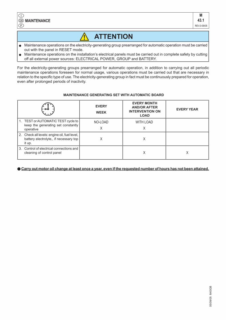
For the electricity-generating groups prearranged for automatic operation, in addition to carrying out all periodic maintenance operations foreseen for normal usage, various operations must be carried out that are necessary in relation to the specific type of use. The electricity-generating group in fact must be continuously prepared for operation, even after prolonged periods of inactivity.
MAINTENANCE GENERATING SET WITH AUTOMATIC BOARD
l Carry out motor oil change at least once a year, even if the requested number of hours has not been attained.
EVERY
WEEK
EVERY MONTHAND/OR AFTER
INTERVENTION ON LOAD
EVERY YEAR
1. TEST or AUTOMATIC TEST cycle to keep the generating set constantly operative
NO-LOADX
WITH LOADX
2. Check all levels: engine oil, fuel level, battery electrolyte,, if necessary top it up.
X X
3. Control of electrical connections and cleaning of control panel X X
ATTENTIONl Maintenance operations on the electricity-generating group prearranged for automatic operation must be carried
out with the panel in RESET mode.l Maintenance operations on the installation’s electrical panels must be carried out in complete safety by cutting
off all external power sources: ELECTRICAL POWER, GROUP and BATTERY.
!
STORAGEM45
REV.0-06/07
In case the machine should not be used for more than 30 days, make sure that the room in which it is stored presents a suitable shelter from heat sources, weather changes or anything which can cause rust, corrosion or damages to the machine.
+ Have qualified personnel prepare the machine for storage.
GASOLINE ENGINE
Start the engine: lt will run until it stops due to the lack of fuel.
Drain the oil from the engine sump and fill it with new oil (see page M25).
Pour about 10 cc of oil into the spark plug hole and screw the spark plug, after having rotated the crankshaft several times.
Rotate the crankshaft slowly until you feel a certain com-pression, then leave it.
In case the battery, for the electric start, is assembled, disconnect it.
Clean the covers and all the other parts of the machine carefully.
Protect the machine with a plastic hood and store it in o dry place.
DIESEL ENGINE
For short periods of time it is advisable, about every 10 days, to make the machine work with load for 15-30 minutes, for a correct distribution of the lubricant, to re-charge the battery and to prevent any possible bloking of the injection system.
For long periods of inactivity, turn to the after soles service of the engine manufacturer.
Clean the covers and all the other parts of the machine carefully.
Protect the machine with a plastic hood and store it in a dry place.
04/0
6/07
M45
GB
In case of necessity for first aid and of fire prevention, see page. M2.5.
IMPORTANTIn the storage operations avoid that polluting substances, liquids, exhausted oils, etc. bring damage to people or things or can cause negative effects to surroindings, health or safety respecting completely the laws and/or dispositions in force in the place.
!
CUST OFFM46
REV.0-06/07
+ Have qualified personnel disassemble the machine and dispose of the parts, including the oil, fuel, etc., in a correct manner when it is to be taken out of service.
As cust off we intend all operations to be made, at utilizer’s care, at the end of the use of the machine.This comprises the dismantling of the machine, the subdivision of the several components for a further reutilization or for getting rid of them, the eventual packing and transportation of the eliminated parts up to their delivery to the store, or to the bureau encharged to the cust off or to the storage office, etc.
The several operations concerning the cust off, invol-ve the manipulation of fluids potentially dangerous such as: lubricating oil and battery electrolyte.
The dismantling of metallic parts liable to cause injuries or wounds, must be made wearing heavy gloves and using suitable tools.
The getting rid of the various components of the machine must be made accordingly to rules in force of law a/o local rules.Particular attention must be paid when getting rid of:lubricating oils, battery electrolyte, and infla-mable liquids such as fuel, cooling liquid.
The machine user is responsible for the observance of the norms concerning the environment conditions with regard to the elimination of the machine being cust off and of all its components.
In case the machine should be cust off without any previous disassembly it is however compulsory to remove:- tank fuel - engine lubricating oil- cooling liquid from the engine- battery
NOTE: BCS is involved with custing off the machine only for the second hand ones, when not reparable.This, of course, after authorization.
In case of necessity for first aid and fire prevention, see page M2.5.
04/0
6/07
M45
GB
IMPORTANTIn the cust-off operations avoid that polluting substances, liquids, exhausted oils, etc. bring damage to people or things or can cause negative effects to surroindings, health or safety respecting completely the laws and/or dispositions in force in the place.
!
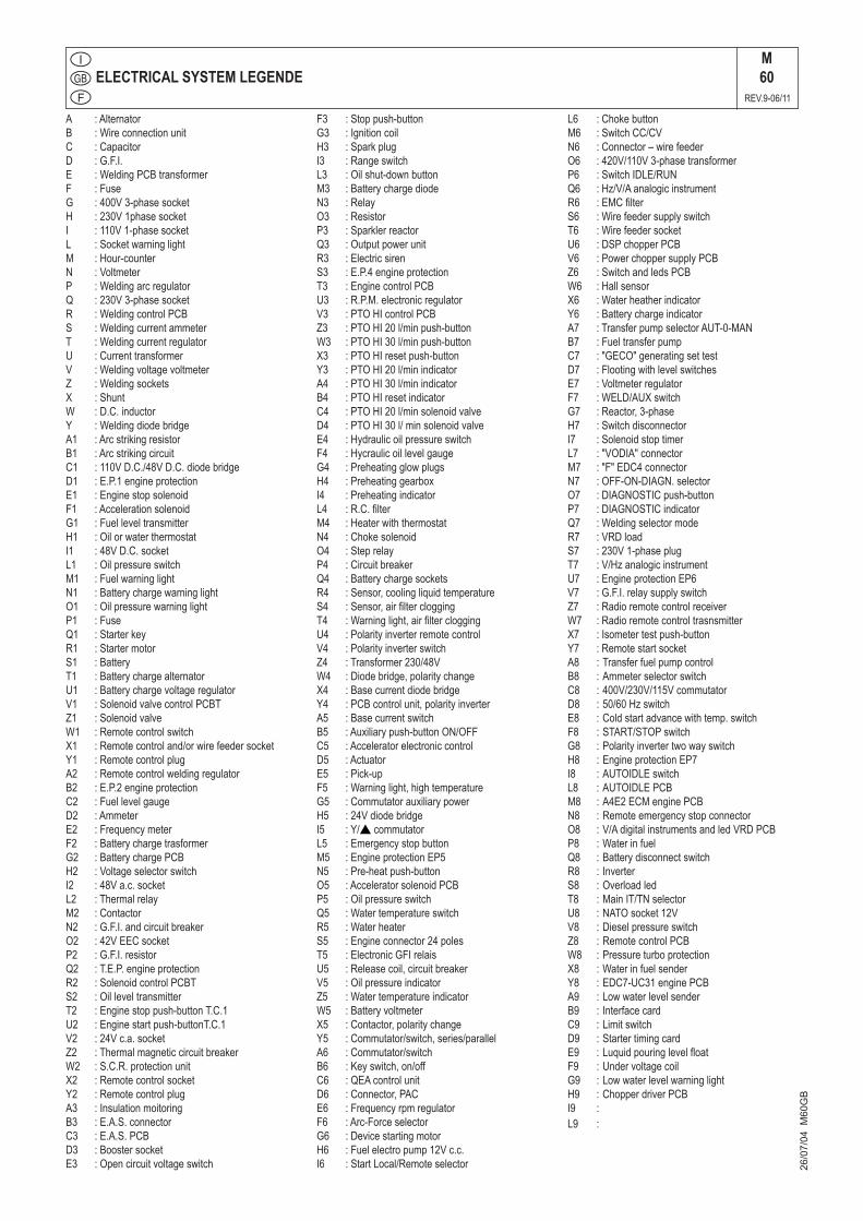
ELECTRICAL SYSTEM LEGENDEM60
REV.9-06/11
26/0
7/04
M60
GB
A :AlternatorB :WireconnectionunitC :CapacitorD :G.F.I.E :WeldingPCBtransformerF :FuseG :400V3-phasesocketH :230V1phasesocketI :110V1-phasesocketL :SocketwarninglightM :Hour-counterN :VoltmeterP :WeldingarcregulatorQ :230V3-phasesocketR :WeldingcontrolPCBS :WeldingcurrentammeterT :WeldingcurrentregulatorU :CurrenttransformerV :WeldingvoltagevoltmeterZ :WeldingsocketsX :ShuntW :D.C.inductorY :WeldingdiodebridgeA1 :ArcstrikingresistorB1 :ArcstrikingcircuitC1 :110VD.C./48VD.C.diodebridgeD1 :E.P.1engineprotectionE1 :EnginestopsolenoidF1 :AccelerationsolenoidG1 :FuelleveltransmitterH1 :OilorwaterthermostatI1 :48VD.C.socketL1 :OilpressureswitchM1 :FuelwarninglightN1 :BatterychargewarninglightO1 :OilpressurewarninglightP1 :FuseQ1 :StarterkeyR1 :StartermotorS1 :BatteryT1 :BatterychargealternatorU1 :BatterychargevoltageregulatorV1 :SolenoidvalvecontrolPCBTZ1 :SolenoidvalveW1 :RemotecontrolswitchX1 :Remotecontroland/orwirefeedersocketY1 :RemotecontrolplugA2 :RemotecontrolweldingregulatorB2 :E.P.2engineprotectionC2 :FuellevelgaugeD2 :AmmeterE2 :FrequencymeterF2 :BatterychargetrasformerG2 :BatterychargePCBH2 :VoltageselectorswitchI2 :48Va.c.socketL2 :ThermalrelayM2 :ContactorN2 :G.F.I.andcircuitbreakerO2 :42VEECsocketP2 :G.F.I.resistorQ2 :T.E.P.engineprotectionR2 :SolenoidcontrolPCBTS2 :OilleveltransmitterT2 :Enginestoppush-buttonT.C.1U2 :Enginestartpush-buttonT.C.1V2 :24Vc.a.socketZ2 :ThermalmagneticcircuitbreakerW2 :S.C.R.protectionunitX2 :RemotecontrolsocketY2 :RemotecontrolplugA3 :InsulationmoitoringB3 :E.A.S.connectorC3 :E.A.S.PCBD3 :BoostersocketE3 :Opencircuitvoltageswitch
F3 :Stoppush-buttonG3 :IgnitioncoilH3 :SparkplugI3 :RangeswitchL3 :Oilshut-downbuttonM3 :BatterychargediodeN3 :RelayO3 :ResistorP3 :SparklerreactorQ3 :OutputpowerunitR3 :ElectricsirenS3 :E.P.4engineprotectionT3 :EnginecontrolPCBU3 :R.P.M.electronicregulatorV3 :PTOHIcontrolPCBZ3 :PTOHI20l/minpush-buttonW3 :PTOHI30l/minpush-buttonX3 :PTOHIresetpush-buttonY3 :PTOHI20l/minindicatorA4 :PTOHI30l/minindicatorB4 :PTOHIresetindicatorC4 :PTOHI20l/minsolenoidvalveD4 :PTOHI30l/minsolenoidvalveE4 :HydraulicoilpressureswitchF4 :HycraulicoillevelgaugeG4 :PreheatingglowplugsH4 :PreheatinggearboxI4 :PreheatingindicatorL4 :R.C.filterM4 :HeaterwiththermostatN4 :ChokesolenoidO4 :SteprelayP4 :CircuitbreakerQ4 :BatterychargesocketsR4 :Sensor,coolingliquidtemperatureS4 :Sensor,airfiltercloggingT4 :Warninglight,airfiltercloggingU4 :PolarityinverterremotecontrolV4 :PolarityinverterswitchZ4 :Transformer230/48VW4 :Diodebridge,polaritychangeX4 :BasecurrentdiodebridgeY4 :PCBcontrolunit,polarityinverterA5 :BasecurrentswitchB5 :Auxiliarypush-buttonON/OFFC5 :AcceleratorelectroniccontrolD5 :ActuatorE5 :Pick-upF5 :Warninglight,hightemperatureG5 :CommutatorauxiliarypowerH5 :24VdiodebridgeI5 :Y/scommutatorL5 :EmergencystopbuttonM5 :EngineprotectionEP5N5 :Pre-heatpush-buttonO5 :AcceleratorsolenoidPCBP5 :OilpressureswitchQ5 :WatertemperatureswitchR5 :WaterheaterS5 :Engineconnector24polesT5 :ElectronicGFIrelaisU5 :Releasecoil,circuitbreakerV5 :OilpressureindicatorZ5 :WatertemperatureindicatorW5 :BatteryvoltmeterX5 :Contactor,polaritychangeY5 :Commutator/switch,series/parallelA6 :Commutator/switchB6 :Keyswitch,on/offC6 :QEAcontrolunitD6 :Connector,PACE6 :FrequencyrpmregulatorF6 :Arc-ForceselectorG6 :DevicestartingmotorH6 :Fuelelectropump12Vc.c.I6 :StartLocal/Remoteselector
L6 :ChokebuttonM6 :SwitchCC/CVN6 :Connector–wirefeederO6 :420V/110V3-phasetransformerP6 :SwitchIDLE/RUNQ6 :Hz/V/AanalogicinstrumentR6 :EMCfilterS6 :WirefeedersupplyswitchT6 :WirefeedersocketU6 :DSPchopperPCBV6 :PowerchoppersupplyPCBZ6 :SwitchandledsPCBW6 :HallsensorX6 :WaterheatherindicatorY6 :BatterychargeindicatorA7 :TransferpumpselectorAUT-0-MANB7 :FueltransferpumpC7 :"GECO"generatingsettestD7 :FlootingwithlevelswitchesE7 :VoltmeterregulatorF7 :WELD/AUXswitchG7 :Reactor,3-phaseH7 :SwitchdisconnectorI7 :SolenoidstoptimerL7 :"VODIA"connectorM7 :"F"EDC4connectorN7 :OFF-ON-DIAGN.selectorO7 :DIAGNOSTICpush-buttonP7 :DIAGNOSTICindicatorQ7 :WeldingselectormodeR7 :VRDloadS7 :230V1-phaseplugT7 :V/HzanalogicinstrumentU7 :EngineprotectionEP6V7 :G.F.I.relaysupplyswitchZ7 :RadioremotecontrolreceiverW7 :RadioremotecontroltrasnsmitterX7 :Isometertestpush-buttonY7 :RemotestartsocketA8 :TransferfuelpumpcontrolB8 :AmmeterselectorswitchC8 :400V/230V/115VcommutatorD8 :50/60HzswitchE8 :Coldstartadvancewithtemp.switchF8 :START/STOPswitchG8 :PolarityinvertertwowayswitchH8 :EngineprotectionEP7I8 :AUTOIDLEswitchL8 :AUTOIDLEPCBM8 :A4E2ECMenginePCBN8 :RemoteemergencystopconnectorO8 :V/AdigitalinstrumentsandledVRDPCBP8 :WaterinfuelQ8 :BatterydisconnectswitchR8 : InverterS8 :OverloadledT8 :MainIT/TNselectorU8 :NATOsocket12VV8 :DieselpressureswitchZ8 :RemotecontrolPCBW8 :PressureturboprotectionX8 :WaterinfuelsenderY8 :EDC7-UC31enginePCBA9 :LowwaterlevelsenderB9 : InterfacecardC9 :LimitswitchD9 :StartertimingcardE9 :LuquidpouringlevelfloatF9 :UndervoltagecoilG9 :LowwaterlevelwarninglightH9 :ChopperdriverPCBI9 :L9 :
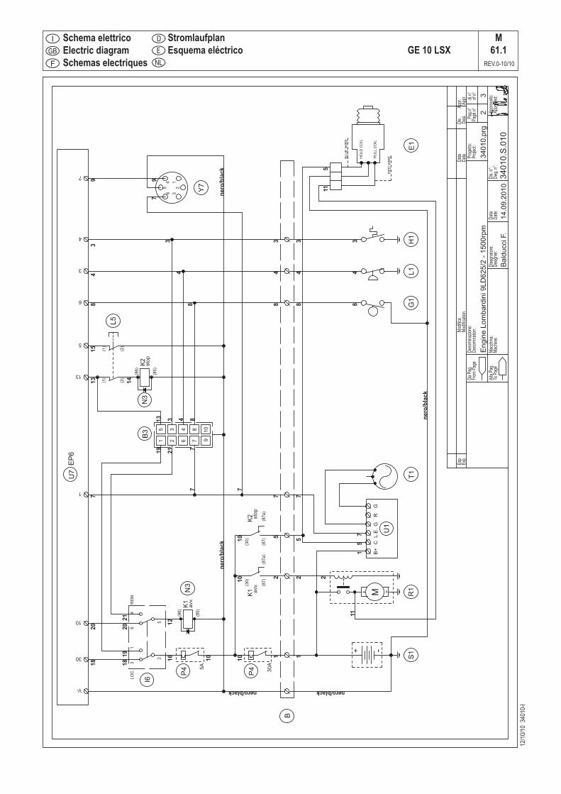
12/10
/10 3
4010
-I
Schema elettricoElectric diagramSchemas electriques
GE 10 LSXM
61.1REV.0-10/10
StromlaufplanEsquema eléctrico
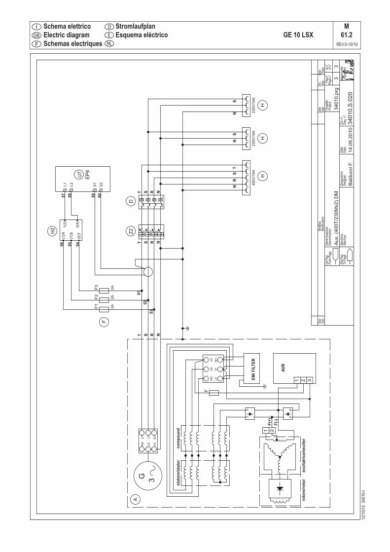
12/10
/10 3
4010
-I
Schema elettricoElectric diagramSchemas electriques
GE 10 LSXM
61.2REV.0-10/10
StromlaufplanEsquema eléctrico

SPARE PARTS LISTR1
REV.0-03/00
The manufacturer guarantees that any request for spare parts will besatisfied.To keep the machine in full working order, when replacement spare parts is required, always ask forgenuine parts only.
When ordering the spare parts, it is recom-mended to indicate:
1) Y serial number
2) Y model of welder and/or generating set
3) u n. table
4) u n. position
5) quantity
14
/12
/98
6Q
16
M3
1
TAVOLA RICAMBI - SPARE PARTS - PIECES DE RECHANGE - ERSATZTEILE
ONOFF
START
*
VE
NULLEITERAUFMASSE
NULVERBONDENMETMASSA
NEUTROCONECTADOAMASA
NEUTRERACCORDEAUBATI
NEUTRALBONDEDTOFRAME
NEUTROCOLLEGATOAMASSA
*
6560
Hz A
1050
1555
500
300
V
ST
RS0
200
100
TR0
h
HOURMETER
I
0
EA
1
2520
125
1-3 13 18 17 16 20-21-22 12
21-22-23
14
11
8
2
19
15
4-5-6
EA
1
12
50
Hz
50
Hz 3
EA
1
4
12
22/0
3/00
R1G
B
The requested data are to be found on the data plate located on the machine structure, quite visible and easy to consult. Y
ABBREVIATIONS AND SYMBOLS:(EV) Whenordering,specifytheenginetypeand theauxiliaryvoltage(ER) Enginewithrecoilstarteronly(ES) Enginewithelectricstarteronly(VE) E.A.Sversiononly.(QM) Whenordering,specifythelengthinmeters(VS) Specialversiononly(SR) Byrequestonly

12/10
/10 3
4010
-I
GE 10 LSXHK15
REV.0-10/10
Tavola ricambiSpare parts tableTable piéces de rechange
E
D
NL
ErsatzteileTabla de recambios
1
2
3
3
4
5
6 7 8 9
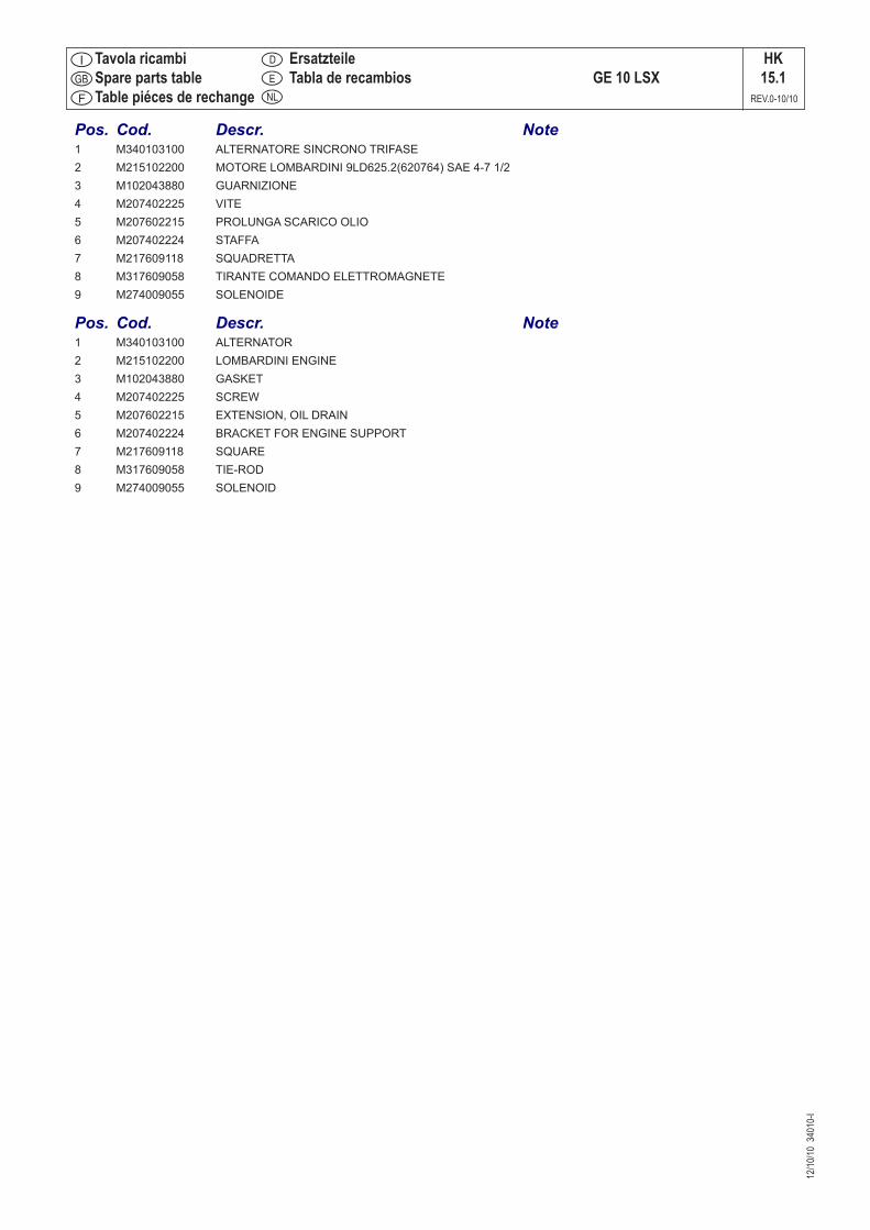
12/10
/10 3
4010
-I
Tavola ricambiSpare parts tableTable piéces de rechange
GE 10 LSXHK15.1
REV.0-10/10
E
D
NL
ErsatzteileTabla de recambios
Pos. Cod. Descr. Note 1 M340103100 ALTERNATORE SINCRONO TRIFASE 2 M215102200 MOTORE LOMBARDINI 9LD625.2(620764) SAE 4-7 1/2 3 M102043880 GUARNIZIONE 4 M207402225 VITE 5 M207602215 PROLUNGA SCARICO OLIO 6 M207402224 STAFFA 7 M217609118 SQUADRETTA 8 M317609058 TIRANTE COMANDO ELETTROMAGNETE 9 M274009055 SOLENOIDE
Pos. Cod. Descr. Note 1 M340103100 ALTERNATOR 2 M215102200 LOMBARDINI ENGINE 3 M102043880 GASKET 4 M207402225 SCREW 5 M207602215 EXTENSION, OIL DRAIN 6 M207402224 BRACKET FOR ENGINE SUPPORT 7 M217609118 SQUARE 8 M317609058 TIE-ROD 9 M274009055 SOLENOID
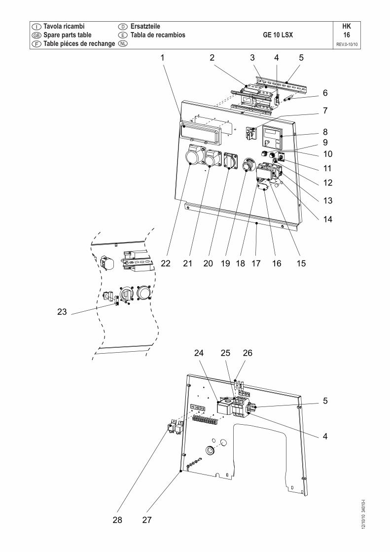
12/10
/10 3
4010
-I
GE 10 LSXHK16
REV.0-10/10
Tavola ricambiSpare parts tableTable piéces de rechange
E
D
NL
ErsatzteileTabla de recambios
1 2 3 4 5
6
7
8
9
10
11
12
13
14
1516171819202122
23
24 25 26
2728
5
4

12/10
/10 3
4010
-I
Tavola ricambiSpare parts tableTable piéces de rechange
GE 10 LSXHK16.1
REV.0-10/10
E
D
NL
ErsatzteileTabla de recambios
Pos. Cod. Descr. Note 1 M317807130 COPERCHIO PROTEZIONE I.D. 2 M105111540 Vedi Cod.219937105 3 M215109705 INTERRUTTORE MAGNETOTERMICO 4 M1241010 PIASTRINA 5 M1243020 GUIDA PER MORSETTIERA 6 M201308039 COLONNETTA 7 M305717315 COMMUTATORE 8 MJK0029770 UNITA’CONTR. MOTORE (EP6) 9 M873407107 DISGIUNTORE TERMICO 30A/250V 10 M352007109 PROTEZIONE TERMICA 5A 11 M102013290 COMMUTATORE 12 M102042740 CAPPUCCIO 13 M105191550 CUSTODIA PER PRESA EAS 14 M105191560 FRUTTO PRESA CONNETTORE 15 M105191570 COPERCHIO PER PRESA EAS 16 M359257032 COPERCH. CHIUS.FORO SCALDIGLIA 17 M340107020 PANNELLO FRONTALE 18 M34010C021 GRUPPO CAVI MOTORE (FRONTALE) 19 M744507219 PULSANTE STOP D’EMERGENZA 20 M259107241 PRESA SCHUKO 16A 230V - 2P+T 21 M307017240 PRESA 220V 16A 22 M305907270 PRESA CEE 16A 400V 3P+N+T 23 M744507237 CONTATTO 24 M343337306 TRASFORMATORE 25 M107509045 PORTAFUSIBILE 26 M1291190 FUSIBILE 27 M250208217 PARATIA SUP. ALTERNATORE 28 M306479199 RELE’ AVV. ELETTRICO Pos. Cod. Descr. Note 1 M317807130 COVER PROTECTION 2 M105111540 See part no. 219937105 3 M215109705 MAGNETOTHERMIC INTERRUPTOR 4 M1241010 SMALL PLATE 5 M1243020 TERMINAL GUIDE 6 M201308039 CONNECTING CYLINDER 7 M305717315 COMMUTATOR 8 MJK0029770 ENGINE CONTROL UNIT EP6 9 M873407107 CIRCUIT BREAKER 30A/250V 10 M352007109 THERMOPROTECTION 11 M102013290 COMMUTATOR 12 M102042740 CAP 13 M105191550 BOX, EAS SOCKET 14 M105191560 SOCKET, EAS 15 M105191570 BLIND PLATE, EAS SOCKET 16 M359257032 COVER 17 M340107020 FRONT PANEL 18 M34010C021 STARTING KEY CABLING 19 M744507219 EMERGENCY PUSH BUTTON STOP 20 M259107241 SOCKET SCHUKO 16A 230V 2P+T 21 M307017240 EEC SOCKET 16A, 220V 2P+T 22 M305907270 EEC SOCKET 16A 400V 3P+N+T 23 M744507237 CONTACT N.C. 24 M343337306 TRANSFORMER 60/5A 25 M107509045 HOLDER, FUSE 26 M1291190 FUSE 27 M250208217 ALTERNATOR TOP BULKHEAD 28 M306479199 RELAY, ELECTRIC START

12/10
/10 3
4010
-I
GE 10 LSXHK17
REV.0-10/10
Tavola ricambiSpare parts tableTable piéces de rechange
E
D
NL
ErsatzteileTabla de recambios
1
2
3
4
56789
10
11
12
13
14
15 (qm)
16
17 (qm)
18
19
20
21
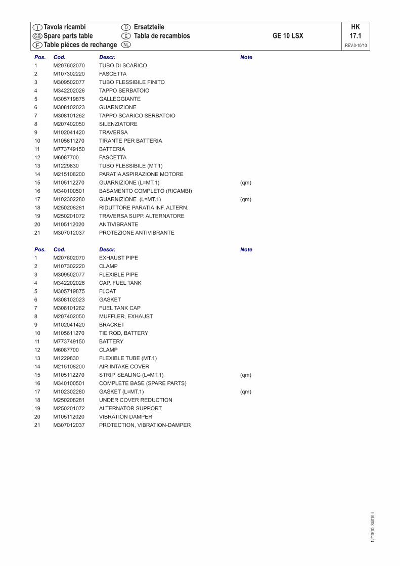
12/10
/10 3
4010
-I
Tavola ricambiSpare parts tableTable piéces de rechange
GE 10 LSXHK17.1
REV.0-10/10
E
D
NL
ErsatzteileTabla de recambios
Pos. Cod. Descr. Note 1 M207602070 TUBO DI SCARICO 2 M107302220 FASCETTA 3 M309502077 TUBO FLESSIBILE FINITO 4 M342202026 TAPPO SERBATOIO 5 M305719875 GALLEGGIANTE 6 M308102023 GUARNIZIONE 7 M308101262 TAPPO SCARICO SERBATOIO 8 M207402050 SILENZIATORE 9 M102041420 TRAVERSA 10 M105611270 TIRANTE PER BATTERIA 11 M773749150 BATTERIA 12 M6087700 FASCETTA 13 M1229830 TUBO FLESSIBILE (MT.1) 14 M215108200 PARATIA ASPIRAZIONE MOTORE 15 M105112270 GUARNIZIONE (L=MT.1) (qm) 16 M340100501 BASAMENTO COMPLETO (RICAMBI) 17 M102302280 GUARNIZIONE (L=MT.1) (qm) 18 M250208281 RIDUTTORE PARATIA INF. ALTERN. 19 M250201072 TRAVERSA SUPP. ALTERNATORE 20 M105112020 ANTIVIBRANTE 21 M307012037 PROTEZIONE ANTIVIBRANTE
Pos. Cod. Descr. Note 1 M207602070 EXHAUST PIPE 2 M107302220 CLAMP 3 M309502077 FLEXIBLE PIPE 4 M342202026 CAP, FUEL TANK 5 M305719875 FLOAT 6 M308102023 GASKET 7 M308101262 FUEL TANK CAP 8 M207402050 MUFFLER, EXHAUST 9 M102041420 BRACKET 10 M105611270 TIE ROD, BATTERY 11 M773749150 BATTERY 12 M6087700 CLAMP 13 M1229830 FLEXIBLE TUBE (MT.1) 14 M215108200 AIR INTAKE COVER 15 M105112270 STRIP, SEALING (L=MT.1) (qm) 16 M340100501 COMPLETE BASE (SPARE PARTS) 17 M102302280 GASKET (L=MT.1) (qm) 18 M250208281 UNDER COVER REDUCTION 19 M250201072 ALTERNATOR SUPPORT 20 M105112020 VIBRATION DAMPER 21 M307012037 PROTECTION, VIBRATION-DAMPER
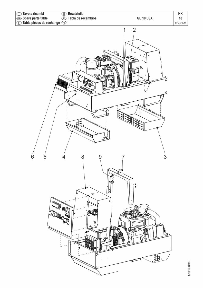
12/10
/10 3
4010
-I
GE 10 LSXHK18
REV.0-10/10
Tavola ricambiSpare parts tableTable piéces de rechange
E
D
NL
ErsatzteileTabla de recambios
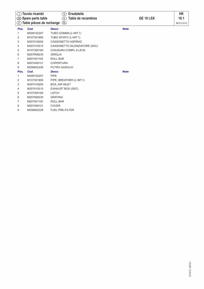
12/10
/10 3
4010
-I
Tavola ricambiSpare parts tableTable piéces de rechange
GE 10 LSXHK18.1
REV.0-10/10
E
D
NL
ErsatzteileTabla de recambios
Pos. Cod. Descr. Note 1 M308102207 TUBO GOMMA (L=MT.1) 2 M107301890 TUBO SFIATO (L=MT.1) 3 M307418200 CASSONETTO ASPIRAZ. 4 M307410515 CASSONETTO SILENZIATORE (SXC) 5 M107300180 CHIUSURA COMPL.A LEVA 6 M207608230 GRIGLIA 7 M207401100 ROLL BAR 8 M207408121 COPERTURA 9 M256602228 FILTRO GASOLIO Pos. Cod. Descr. Note 1 M308102207 PIPE 2 M107301890 PIPE, BREATHER (L=MT.1) 3 M307418200 BOX, AIR INLET 4 M307410515 EXHAUST BOX (SXC) 5 M107300180 LATCH 6 M207608230 GRATING 7 M207401100 ROLL BAR 8 M207408121 COVER 9 M256602228 FUEL PRE-FILTER
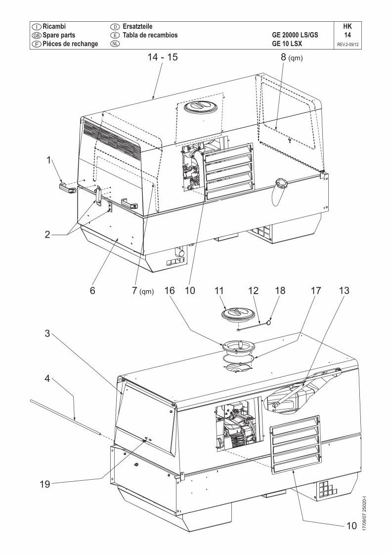
17/0
9/07
250
20-I
GE 20000 LS/GSGE 10 LSX
HK14
REV.2-09/12
RicambiSpare partsPiéces de rechange
E
D
NL
ErsatzteileTabla de recambios
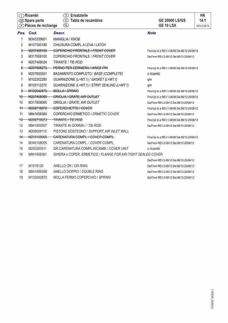
17/0
9/07
250
20-I
RicambiSpare partsPiéces de rechange
E
D
NL
ErsatzteileTabla de recambios GE 20000 LS/GS
GE 10 LSX
HK14.1
REV.2-09/12
Pos. Cod. Descr. Note 1 M343339601 MANIGLIA / KNOB 2 M107300180 CHIUSURA COMPL.A LEVA / LATCH 3 M207408100 COPERCHIO FRONTALE / FRONT COVER Fino/Up to a REV.1-06/08 Del.66/12-25/06/12
3 M317608100 COPERCHIO FRONTALE / FRONT COVER Da/From REV.2-09/12 Del.66/12-25/06/12
4 M207408024 TIRANTE / TIE-ROD 5 M207608270 PERNO PER CERNIERA / HINGE PIN Fino/Up to a REV.1-06/08 Del.66/12-25/06/12
6 M207600501 BASAMENTO COMPLETO / BASE (COMPLETE) x ricambi 7 M102302280 GUARNIZIONE (L=MT.1) / GASKET (L=MT.1) qm 8 M105112270 GUARNIZIONE (L=MT.1) / STRIP, SEALING (L=MT.1) qm 9 M102042870 MOLLA / SPRING Fino/Up to a REV.1-06/08 Del.66/12-25/06/12
10 M207408065 GRIGLIA / GRATE, AIR OUTLET Fino/Up to a REV.1-06/08 Del.66/12-25/06/12 10 M317608065 GRIGLIA / GRATE, AIR OUTLET Da/From REV.2-09/12 Del.66/12-25/06/12
11 M209718070 COPERCHIETTO / COVER Fino/Up to a REV.1-06/08 Del.66/12-25/06/12
11 M841658360 COPERCHIO ERMETICO / ERMETIC COVER Da/From REV.2-09/12 Del.66/12-25/06/12
12 M209718073 TIRANTE / TIE-ROD Fino/Up to a REV.1-06/08 Del.66/12-25/06/12
12 M841659357 TIRANTE IN GOMMA / / TIE-ROD Da/From REV.2-09/12 Del.66/12-25/06/12
13 M209508115 PISTONE SOSTEGNO / SUPPORT, AIR INLET WALL 14 M215108005 CARENATURA COMPL. / COVER COMPL. Fino/Up to a REV.1-06/08 Del.66/12-25/06/12 14 M340108005 CARENATURA COMPL. / COVER COMPL. Da/From REV.2-09/12 Del.66/12-25/06/12 15 M250200511 GR.CARENATURA COMPL.RICAMBI / COVER UNIT x ricambi 16 M841658361 GHIERA x COPER. ERMETICO / FLANGE FOR AIR-TIGHT SEALED COVER Da/From REV.2-09/12 Del.66/12-25/06/12 17 M1018130 ANELLO OR / OR RING Da/From REV.2-09/12 Del.66/12-25/06/12 18 M841659358 ANELLO DOPPIO / DOUBLE RING Da/From REV.2-09/12 Del.66/12-25/06/12 19 M102042870 MOLLA FERMO COPERCHIO / SPRING Da/From REV.2-09/12 Del.66/12-25/06/12

11/1
2/97
KA
CTL 400M217600140
KA7
REV.0-02/97
Pos. Cod. Descr. Descr. Note
1 M0000217600141 GR.TIMONE, PIEDE X TRAINO LENTO KIT SITE TOW2 M102351750 PIEDE DI STAZIONAMENTO PARKING STAND3 M207401150 TIMONE TOW BAR4 M0000217600142 GR. ASSALE, RUOTE TRAINO LENTO KIT SITE TOW 5 M207401160 ASSALE AXLE6 M102351740 RUOTA WHEEL

TCM35M930350000
KD8
REV.0-06/06
16/0
6/03
KD
Pos. Cod. Descr. Descr.1 M930357219 INTERRUTTORE 2P 16A INTERRUPTER 2P 16A2 M930359913 SCATOLA COMPLETA CASE, COMPL.3 M930357227 LAMPADA 24V WARNING LIGHT 24V4 M930357231 PORTALAMPADA SPIA ROSSA WARNING LIGHT HOLDER5 M93035C060 GR. CAVI TCM TCM CABLE KIT6 M930350000 TCM35 COMPLETO COMPLETE TCM35
