gcse 25 currentelectricity
DESCRIPTION
.TRANSCRIPT

AQA GCSE Physics 2-5
Current Electricity
GCSE Physics pages 170 to 183
October 28th 2010

AQA GCSE SpecificationCURRENT ELECTRICITY12.6 What does the current through an electrical circuit depend on?
Using skills, knowledge and understanding of how science works:• to interpret and draw circuit diagrams using standard symbols.• to apply the principles of basic electrical circuits to practical situations.
Skills, knowledge and understanding of how science works set in the context of:• Current-potential difference graphs are used to show how the current through a component varies with the potential difference across it.• The current through a resistor (at a constant temperature) is directly proportional to the potential difference across the resistor.• Potential difference, current and resistance are related by the equation:potential difference = current × resistance• The resistance of a component can be found by measuring the current through, and potential difference across, the component.• The resistance of a filament lamp increases as the temperature of the filament increases.• The current through a diode flows in one direction only. The diode has a very high resistance in the reverse direction.• The resistance of a light-dependant resistor (LDR) decreases as light intensity increases.• The resistance of a thermistor decreases as the temperature increases (ie knowledge of negative temperature coefficient thermistor only is required).• The current through a component depends on its resistance. The greater the resistance the smaller the current for a given potential difference across the component.• The potential difference provided by cells connected in series is the sum of the potential difference of each cell (depending on the direction in which they are connected).• For components connected in series:– the total resistance is the sum of the resistance of each component– there is the same current through each component– the total potential difference of the supply is shared between the components.• For components connected in parallel:– the potential difference across each component is the same– the total current through the whole circuit is the sum of the currents through the separate components.
Electric circuits
An electric current will only flow if there is a complete, unbroken electric circuit, that contains a power supply.
A circuit diagram uses a standard set of symbols to show how electrical components are connected together.

Circuit symbols
cell
wire junction
switch
a cell is required to push electrons around a circuit
a switch enables the current in a circuit to be turned on or off
wire wires should always been drawn as straight lines
battery a battery consists of two or more cells

ammeterA
V voltmeter
measures electric current in amperes (A)
measures potential difference in volts (V)
indicator often a light bulb – this is used to show whether or not a circuit is on
light bulb old symbol – the indicator symbol is now used

fixed resistor
a resistor is used to limit the current in a circuit
variable resistor
light dependent resistor (LDR)
thermistor a device whose resistance decreases with temperature
a device whose resistance decreases with brightness

diode a diode only allows current to flow in one direction (indicated by the arrow)
fuse
heater
light emitting diode (LED)
a diode that emits light when it allows the flow of electric current
a fuse is designed to melt and so break an electric circuit when too much electric current flows
a device used to convert electrical energy to heat

Electric current flow
Electric current flows from the POSITIVE terminal of a power supply around a circuit to the NEGATIVE terminal.
The longer thinner line of the symbol for a cell is the positive terminal.
In the circuit above the diode is aligned so that it allows current to flow through the radio.

Completesymbol component symbol component
A
indicator
ammeter
diode
heater
thermistor
cell LDR
resistor

Question
Draw a circuit diagram for the torch shown below.

Electric circuitsNotes questions from pages 170 & 171
1. For an electric circuit to work, what must be true?
2. Copy Figure 2 on page 170.3. Copy and answer questions (a), (b) and (c) on
pages 170 and 171. Include the diagrams with questions (b) and (c).
4. Copy the Key Points on page 171.5. Answer the summary questions on page 171.

Electric circuits ANSWERS
In text questions:
(a) So current passes through it and through the lamp.
(b) Two cells, a switch and a heater.
(c) No.
Summary questions:
1. Cell, switch, indicator, fuse.
2. (a) The diode arrow should be pointing to the right.
(b) A variable resistor.

ResistanceResistance is the opposition that an electrical device has to the flow of electrical current.
All devices have some resistance. A resistor is a device that has a particular resistance.
a resistor
circuit symbol for a resistor
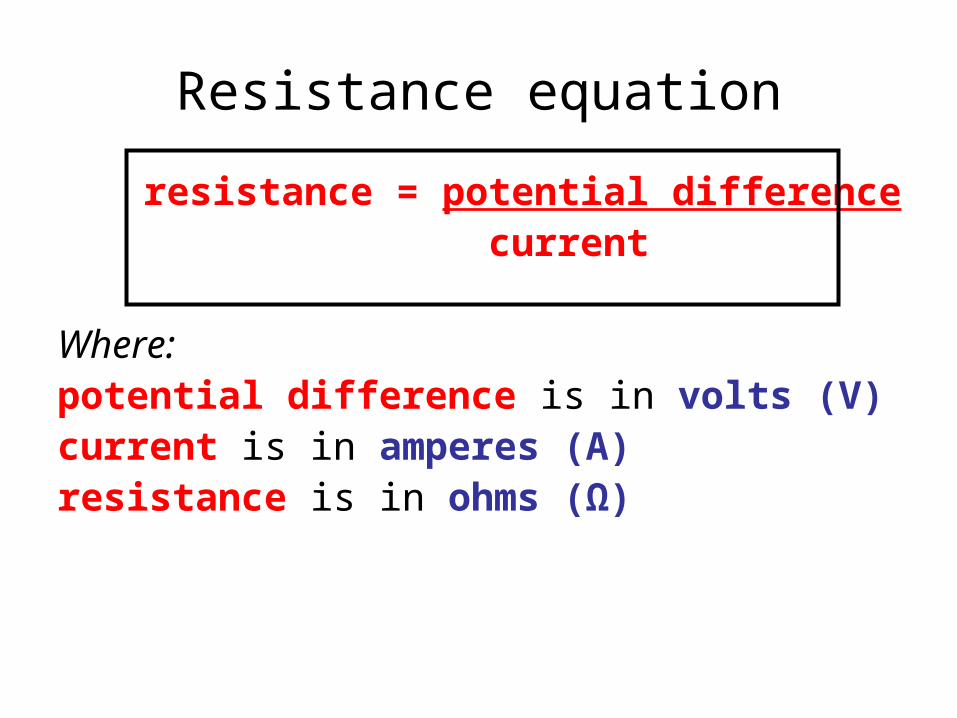
Resistance equation
resistance = potential differencecurrent
Where:potential difference is in volts (V)current is in amperes (A)resistance is in ohms (Ω)

Also:
potential difference = current x resistance
and:
current = potential difference
resistancepotential
difference
resistancecurrent

Measuring Resistance
The resistance of a component can be found by measuring the current through, and potential difference across, the component.
Circuit used for measuring the resistance of an indicator lamp

Question 1
Calculate the resistance of a lamp if a potential difference of 12V causes a current of 3A to flow through the lamp.
resistance = potential differencecurrent
= 12V / 3Aresistance = 4 ohms (4Ω)

Question 2
Calculate the resistance of a heater if a potential difference of 230V causes a current of 200mA to flow through the heater.
resistance = potential difference current
= 230V / 200mA= 230V / 0.200Aresistance = 1150 Ω

Question 3
Calculate the potential difference across a resistance of 40Ω when a current of 5A is flowing.
potential difference = current x resistance = 5A x 40Ω
potential difference = 200V

Question 4
Calculate the current flowing through a wire of resistance of 8Ω when a potential difference of 12V is connected to the wire.
current = potential differenceresistance
= 12V / 8Ωcurrent = 1.5A

Answerspotential
differencecurrent resistance
20 V 4 A
5 A 40 Ω
300 V 0.20 50 Ω
8 V 500 mA
3 kV 150 Ω
4 mA 30 kΩ
5 Ω
200 V
6 A
16 Ω
20 A
120 V
Complete:

Current-potential difference graphs
These are used to show how the current through a component varies with the potential difference across it.
The circuit opposite could be used to obtain a current-potential difference graph of a wire.

The current-potential difference graph of a resistor at a constant temperature
The graph is a straight line through the origin.
The graph shows that the current through a resistor is directly proportional to the potential difference across the resistor.
Typical results:

Choose appropriate words to fill in the gaps below:
An electric ________ will only flow around a circuit if there are no ______ in the circuit.
All components have __________. The greater the resistance the ________ is the current for the same applied potential difference. Resistance is measured in ______.
A current – potential difference graph for a ________ is a straight line through the _______. This shows that the current through the resistor is ___________ to the applied potential difference.
resistance currentresistor ohmsgaps originsmaller
WORD SELECTION:
proportional
resistance
current
resistor
ohms
gaps
origin
smaller
proportional

ResistanceNotes questions from pages 172 & 173
1. Copy Figure 1 on page 172 and explain the placement of the two meters.
2. Explain what causes a conductor to have resistance.3. Copy the equation for resistance on page 172 along with the units
used and the symbolic version of the equation.4. Copy and answer question (a) on page 172.5. What is Ohm’s law?6. Sketch the current-potential difference graph of a wire and explain
how this graph shows that the wire obeys Ohm’s law.7. Copy and answer question (b) on page 173.8. Copy the Key Points on page 173.9. Answer the summary questions on page 173.

Resistance ANSWERS
In text questions:
(a) 8.0 Ω
(b) 10 Ω
Summary questions:
1. (a) The diagram should be the same as Figure 2 on page 173 but it does not need to have the variable resistor.
(b) 8.0 Ω
2. W = 6.0Ω; X = 80V;
Y = 2.0A; Z = 24Ω

Filament lamp
The resistance of a filament lamp increases as the temperature of the filament increases.
Reversing the potential difference (negative values on the graph) reverses the direction of the electric current but does not change the shape of the curve.

Diode
The current through a diode flows in one direction only.
The diode has a very high resistance in the reverse direction.

Thermistor
The resistance of a thermistor decreases as the temperature increases.
The higher temperature line therefore has a greater slope than the lower temperature case.

Light dependent resistor (LDR)
The resistance of a light-dependant resistor decreases as light intensity increases.
The bright light line therefore has a greater slope than the dim light case.

Choose appropriate words to fill in the gaps below:
The resistance of a filament lamp _________ when the lamp comes on and the filament rises in ___________.
A ______ only allows electric current to flow one way. The allowed direction is shown by the _______ on its circuit symbol.
The ________ of a thermistor decreases if its temperature is increased. The resistance of a LDR _________ if the _______level is increased.
resistancedecreasesarrow diode lightincreases
WORD SELECTION:
temperature
resistance
decreases
arrow
diode
light
increases
temperature

More current-potential difference graphs Notes questions from pages 174 & 175
1. Copy Figure 1 on page 174 and explain why the resistance of a filament lamp varies with potential difference.
2. Copy Figure 2 on page 174 and explain how the resistance of a diode varies with potential difference.
3. Copy and answer questions (a) and (b) on page 174.4. Copy Figure 4 on page 175 and explain how the resistance of a
thermistor varies with temperature.5. Copy Figure 5 on page 175 and explain how the resistance of a
light dependent resistor varies with brightness.6. Copy and answer question (c) on page 175.7. Copy the Key Points on page 175.8. Answer the summary questions on page 175.

More current-potential difference graphs ANSWERS
In text questions:
(a) (i) 5.0 Ω; (ii) 10 Ω
(b) It decreases
(c) The resistance is constant.
Summary questions:
1. (a) thermistor
(b) diode
(c) filament lamp
(d) resistor
2. (a) 15 Ω
(b) The ammeter reading increases because the resistance of the thermistor decreases.

Series circuitsCircuit components are said to be connected in series if the same electric current passes through each of them in turn.
The cell and the two lamps are in series with each other and so the same electric current passes through all of them.
3A
3A
3A 3A3A
3A
3A

Using cells in series to make a battery
The total potential difference (voltage) provided by cells connected in series is the sum of the potential difference of each cell (depending on the direction in which they are connected).
With 1.5V cells:
3V battery
1.5V battery
4.5V battery

Resistors in series
The total resistance is the sum of the resistance of each component.
Total resistance = R1 + R2
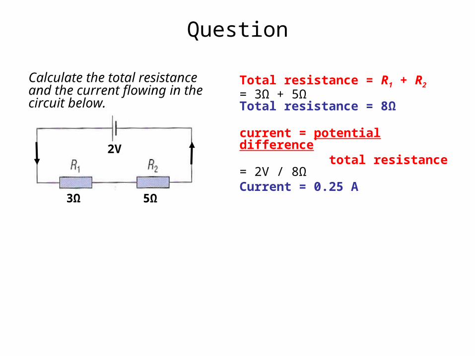
Question
Calculate the total resistance and the current flowing in the circuit below.
Total resistance = R1 + R2
= 3Ω + 5ΩTotal resistance = 8Ω
current = potential difference total resistance
= 2V / 8ΩCurrent = 0.25 A
2V
3Ω 5Ω

Voltages in series circuits
The total potential difference of the supply is shared between the components.
Vs
V1 V2
Vs = V1 + V2

QuestionComplete the table opposite for the various settings of the variable resistor if the power supply voltage, Vs is 3V.
Vs
V1 V2
lamp condition
V1 V2
dim 2.5V 0.5V
bright 1.0V 2.0V
very bright
0.3V 2.7V

Complete the table for the circuit below:
Vs
V1 V2
current
Vs R1 R2Total
resistance V1 V2current
4V 2Ω 6Ω 8Ω 1V 3V 0.5A
10V 2Ω 3Ω 5Ω 4V 8V 2A
12V 8Ω 40Ω 48Ω 2V 10V 0.25A
3V 20Ω 40Ω 60Ω 1V 2V 50mA

Choose appropriate words to fill in the gaps below:
When components are _________ together in series they will all have the same _________ flowing through each of them.
The total voltage of a ________ made up of cells connected in _______ is equal to the sum of the cell ________ differences provided that the cells are all connected the ______ way around.
The total resistance of __________ connected together in series is equal to the ______ of the individual resistances.
seriesconnected currentbatterypotential resistorssame
WORD SELECTION:
sum
series
connected
current
battery
potential
resistors
same
sum
Series circuitsNotes questions from pages 176 & 177
1. Copy and explain the two circuit rules for series circuits. Draw Figures 1 and 2 on page 176.
2. Copy and answer questions (a) and (b) on page 176.3. Explain what happens when cells are connected
together in series.4. Copy Figure 4 on page 177 and explain what happens
when resistors are connected in series.5. Copy and answer questions (c) and (d) on page 177.6. Copy the Key Points on page 177.7. Answer the summary questions on page 177.

Series circuits ANSWERS
In text questions:
(a) 0.12 A
(b) 0.4 V
(c) 1.1 V
(d) 5 Ω
Summary questions:
1. (a) The same as
(b) Less than
2. (a) (i) 12 Ω (ii) 3.0 V
(b) 3V / 12Ω = 0.25 A
(c) P = 0.5V; Q = 2.5V

Parallel circuits
The potential difference (voltage) across each component connected in parallel is the same.
The voltmeter reading for component X, V1 will be the same as the voltmeter reading for component Y, V2.

The total current through the whole circuit is the sum of the currents through the separate components.
Currents in parallel circuits
5A
2A3A
5A
3A
2A

What are the advantages of connecting two lamps in parallel rather than in series to a power supply?
Question 1
When connected in parallel:
1. the lamps are brighter than when connected in series
2. the lamps can be controlled individually with switches
3. one lamp will continue working even if the other does not
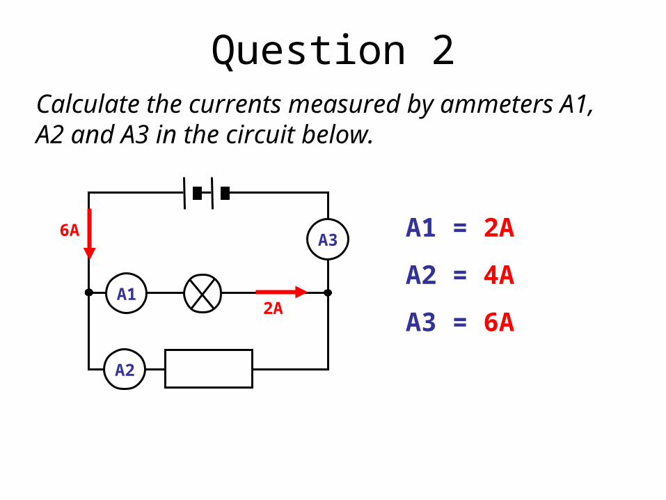
Calculate the currents measured by ammeters A1, A2 and A3 in the circuit below.
Question 2
6A
2A
A2
A1
A3 A1 = 2A
A2 = 4A
A3 = 6A

Calculate the currents through the 6Ω and 4Ω resistors in the circuit below.
Question 3
12V
4Ω
6Ω
Both resistors will have the same potential difference = 12Vcurrent = potential difference
resistance
For the 6Ω resistor:=12V / 6Ωcurrent through 6Ω resistor = 2A
For the 4Ω resistor:=12V / 4Ωcurrent through 6Ω resistor = 3A

Calculate the resistance of R in the circuit below if the ammeter reads 5A.
Question 4
Both resistors will have the same potential difference = 6V
For the 2Ω resistor:current = potential difference
resistance= 6V / 2Ω= 3A
As the total current, measured by the ammeter, is 5A there must be 2A flowing through resistor R. resistance = potential difference
current=6V / 2Aresistance of R = 3Ω
6V
2Ω
R
A
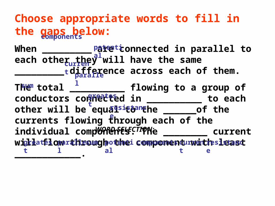
Choose appropriate words to fill in the gaps below:
When _________ are connected in parallel to each other they will have the same _________ difference across each of them.
The total __________ flowing to a group of conductors connected in __________ to each other will be equal to the ______of the currents flowing through each of the individual components. The ________ current will flow through the component with least ____________.
resistancegreatest currentcomponentspotentialsum
WORD SELECTION:
parallel
resistance
greatest
current
components
potential
sum
parallel

Parallel circuitsNotes questions from pages 178 & 179
1. Draw a diagram to illustrate the rule about currents, stated on page 178, through parallel components.
2. Copy Figure 2 on page 178 and explain the rule about potential difference in a parallel circuit.
3. Copy a different version of the worked example on page 179. In your version show the calculations if the battery was 12V instead of 6V.
4. Copy and answer questions (a) and (b) on pages 178 and 179.
5. Copy the Key Points on page 179.6. Answer the summary questions on page 179.

Parallel circuits ANSWERS
In text questions:
(a) 0.30 A
(b) The 3Ω resistor
Summary questions:
1. (a) Potential difference
(b) current
2. (a) R1: 3A;
R2: 2A;
R3: 1A
(b) 6A

Virtual Physics Laboratory SimulationsNOTE: Links work only in school
Explaining Electricity.exe – Explain the relationships between charge, current, energy and PD. DC\Cicuits.exe - Series & parallel circuitsI V Characteristics.exe - Includes diodeLight Dependent Resistor.exe Thermistor.exe Electrometer.exe – ElectroscopeElectrostatic Induction.exe – Does not work in all casesElectrostatic Pendulum.exe - Shows how current is produced by charge flowVan der Graaf.exe

Online Simulations - 1Signal Circuit - PhET - Why do the lights turn on in a room as soon as you flip a switch? Flip the switch and electrons slowly creep along a wire. The light turns on when the signal reaches it. Charge flow with resistors in series and parallel - NTNU Circuit Construction DC Only - PhET - An electronics kit in your computer! Build circuits with resistors, light bulbs, batteries, and switches. Take measurements with the realistic ammeter and voltmeter. View the circuit as a schematic diagram, or switch to a life-like view. Circuit Construction AC + DC - PhET - This new version of the CCK adds capacitors, inductors and AC voltage sources to your toolbox! Now you can graph the current and voltage as a function of time. Fifty-Fifty Game on Conductors & Insulators - by KT - Microsoft WORD Hidden Pairs Game Circuit Pairs Quiz basic circuit symbols with this pairs game - by eChalk Hidden Pairs Game on Circuit Symbols - by KT - Microsoft WORD Light bulb connected to a battery & switch Battery_bulb.ckt - Crocodile Clip Presentation Two light bulbs connected in series to a battery & switch Battery_series_bulbs.ckt - Crocodile Clip Presentation Two light bulbs connected in parallel to a battery & switch Battery_parallel_bulbs.ckt - Crocodile Clip Presentation Selection of circuits for 3rd Year Electricity Electric Current Quizes - by KT - Microsoft WORD
Battery Voltage - Colorado - Look inside a battery to see how it works. Select the battery voltage and little stick figures move charges from one end of the battery to the other. A voltmeter tells you the resulting battery voltage. Battery-Resistor Circuit - PhET - Look inside a resistor to see how it works. Increase the battery voltage to make more electrons flow though the resistor. Increase the resistance to block the flow of electrons. Watch the current and resistor temperature change Light bulb being controlled by a variable resistor VariableR_bulb.ckt - Crocodile Clip Presentation Motor being controlled by a variable resistor VariableR_motor.ckt - Crocodile Clip Presentation Electric circuits with resistors - series & parallel with meters - netfirms Variable resistor with an ammeter & a voltmeter Resist.ckt - Crocodile Clip Presentation Resistance measurement demo - Molecular Expressions Resistance combination - Fendt Resistors in parallel & series - Multimedia Ohm's Law - PhET - See how the equation form of Ohm's law relates to a simple circuit. Adjust the voltage and resistance, and see the current change according to Ohm's law. The sizes of the symbols in the equation change to match the circuit diagram.

Online Simulations - 2Resistors in parallel & series - Multimedia Ohm's Law - PhET - See how the equation form of Ohm's law relates to a simple circuit. Adjust the voltage and resistance, and see the current change according to Ohm's law. The sizes of the symbols in the equation change to match the circuit diagram. Ohm's Law - Fendt Thermistor Therm.ckt - Crocodile Clip Presentation Light Dependent Resistor (LDR) LDR.ckt - Crocodile Clip Presentation Resistance in a Wire - PhET - Learn about the physics of resistance in a wire. Change its resistivity, length, and area to see how they affect the wire's resistance. The sizes of the symbols in the equation change along with the diagram of a wire. Resistance Wire Simulation - by KT - Designed for the GCSE Investigation but can also be used to show the affect of source resistance and to show power supply maximum power. Introduction . Worksheets for GCSE investigation Conductivity - PhET - Experiment with conductivity in metals, plastics and photoconductors. See why metals conduct and plastics don't, and why some materials conduct only when you shine a flashlight on them. Semiconductors - PhET - Dope the semiconductor to create a diode or transistor. Watch the electrons change position and energy. Comparing the action of a variable resistor and a potential divider VarRPotD - Crocodile Clip Presentation
Forward Biased Silicon Diode Diodef.ckt - Crocodile Clip Presentation Reversed Biased Silicon Diode Dioder.ckt - Crocodile Clip Presentation BBC KS3 Bitesize Revision: Circuit symbols Series and parallel circuits Measuring current and voltage Current in series circuits Heating effect of current BBC AQA GCSE Bitesize Revision: Circuit symbols & diagrams Series & parallel connection Current & potential difference Cells and circuits Series circuits Parallel circuits Calculating resistance Changing resistance Filament lamp with IV curve Thermistors & LDRs The diode

Circuits in control Notes questions from pages 180 & 181
1. Answer questions 1 and 2 on page 181.

Circuits in control ANSWERS
1. A daytime fire alarm
2. A greenhouse alarm if the sunlight is too strong or the temperature is too high.

How Science Works ANSWERS
(a) minus 50oC to 150oC.(b) It might work, but it would not be accurate.(c) 0.1oC(d) It cannot be relied on to be giving a more accurate temperature
than 0.3oC above or below that recorded.(e) The company could be biased.(f) It had been independently calibrated.(g) 37.45oC and 37.4oC(h) The technician could have checked the temperature of the water
with the two thermometers at the same time.(i) No. The new thermometer had a range of minus 50oC to 150oC.(j) No. Because they are all within the ± 0.3oC