gc introduction
TRANSCRIPT
Introduction for Chromatography
1

2
Chromatography
Analysis of complex mixtures (Organic Compounds)
Separation & Determination
(a) Qualitative(b) Quantitative
Sample
Mixture of organic compounds dissolved in an organic solvent.
3
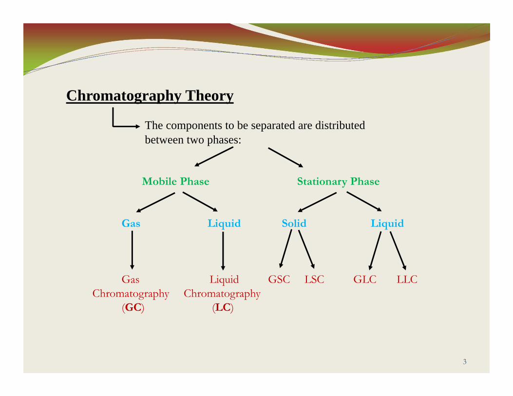
Chromatography Theory
The components to be separated are distributed between two phases:
Mobile Phase Stationary Phase
Gas Liquid Solid Liquid
Gas Liquid GSC LSC GLC LLCChromatography Chromatography
(GC) (LC)
Gas Chromatography (GC)
4
5
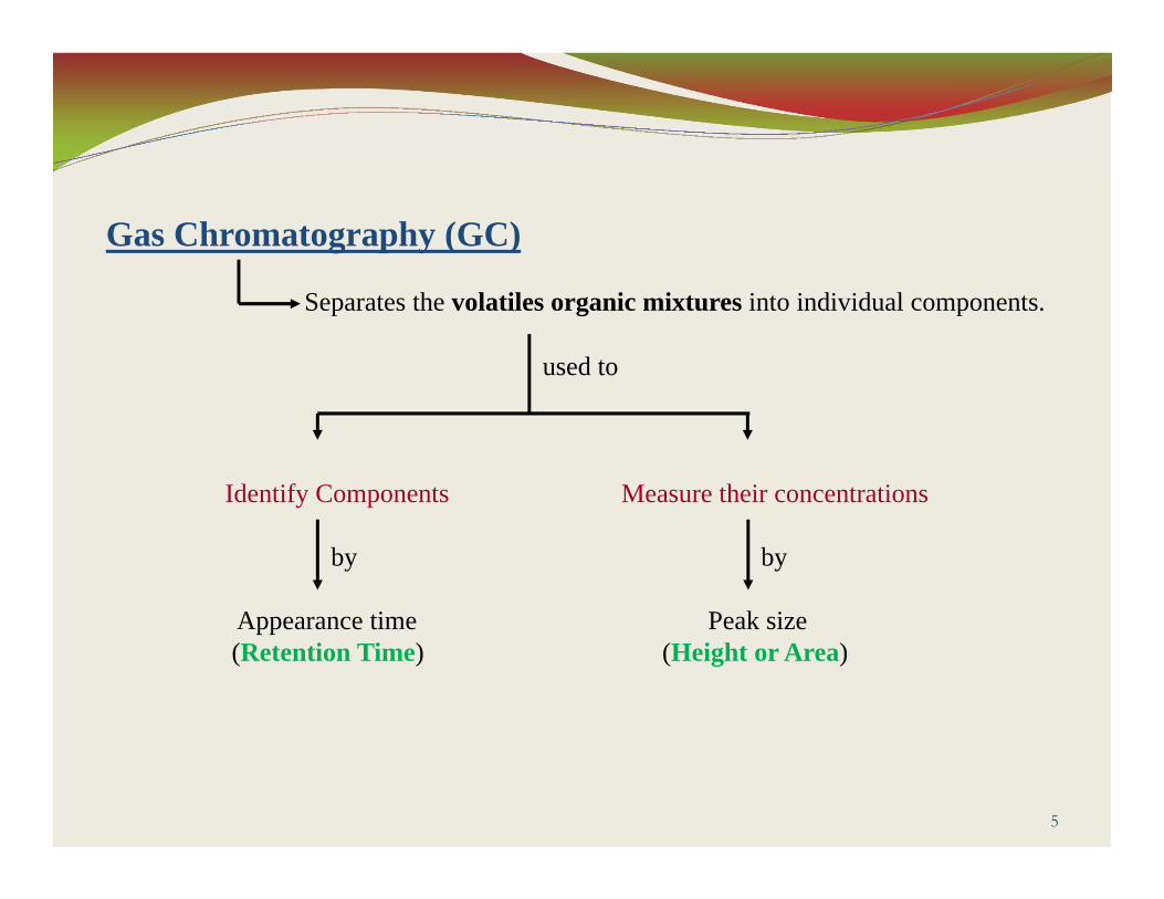
Gas Chromatography (GC)
Separates the volatiles organic mixtures into individual components.
used to
Identify Components Measure their concentrations
by by
Appearance time Peak size(Retention Time) (Height or Area)
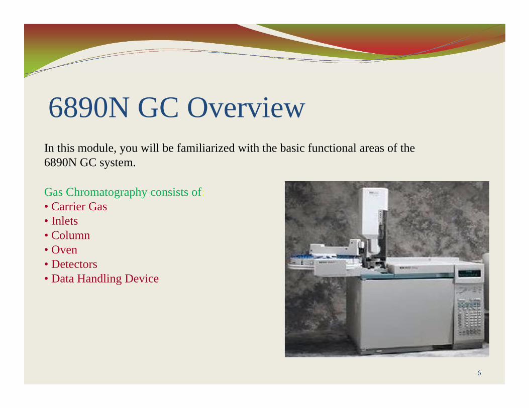
6890N GC Overview
6
In this module, you will be familiarized with the basic functional areas of the 6890N GC system.
Gas Chromatography consists of:• Carrier Gas • Inlets• Column• Oven• Detectors• Data Handling Device

1. Carrier Gas
7
8
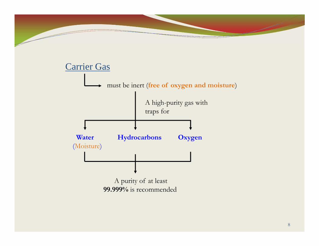
Carrier Gas
must be inert (free of oxygen and moisture)
A high-purity gas with traps for
Water Hydrocarbons Oxygen(Moisture)
A purity of at least 99.999% is recommended

9
Carrier Gasis responsible for
(a) Carrying the vaporized sample through the inlets, column, and the detectors.
(b) Sample component desorption during the sorption-desorption process inside the column.
Carrier Gas
There are many types of carrier gases used in GC analysis.
such as
Helium Nitrogen Argon/5%Methane Hydrogen
Note:For capillary applications, some methods recommend using Hydrogen as a carrier gas.
10
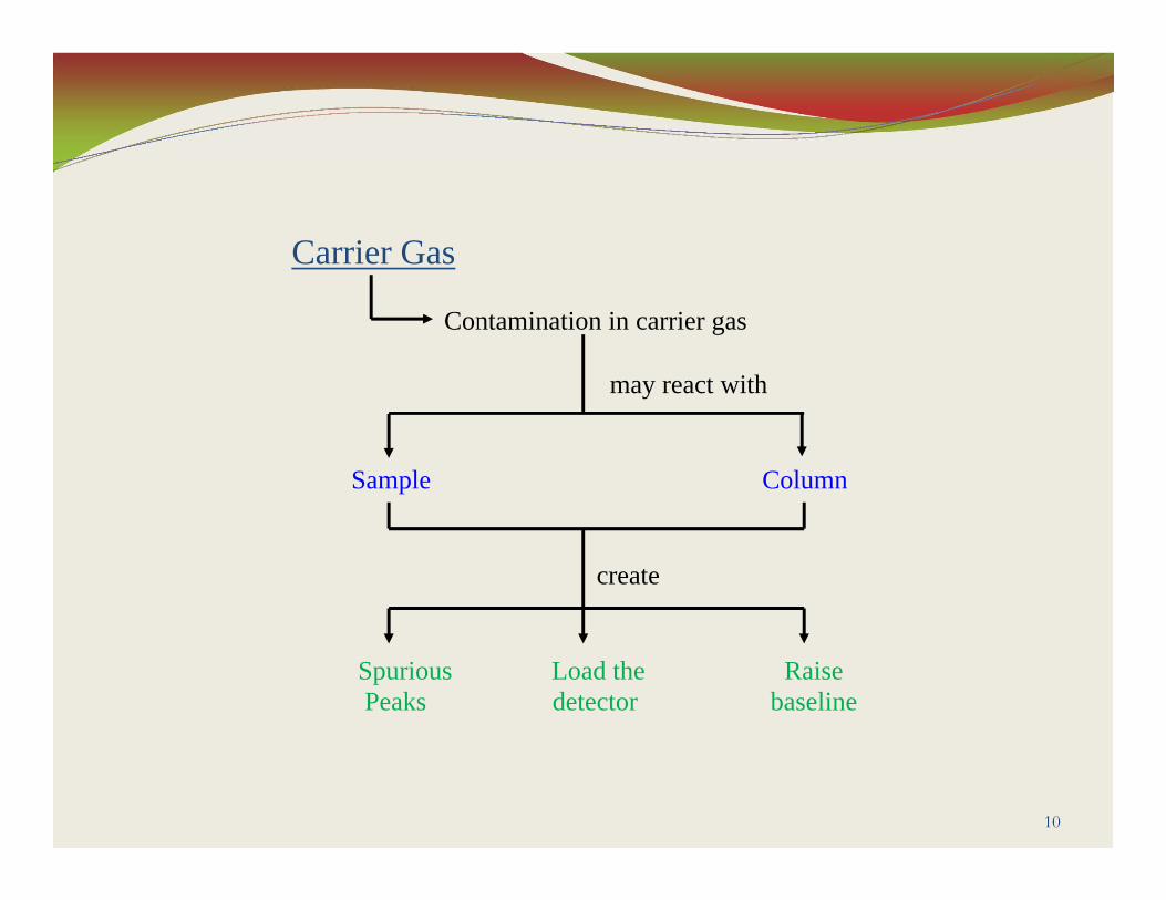
Carrier Gas
Contamination in carrier gas
may react with
Sample Column
create
Spurious Load the RaisePeaks detector baseline

2. Inlets
11
12
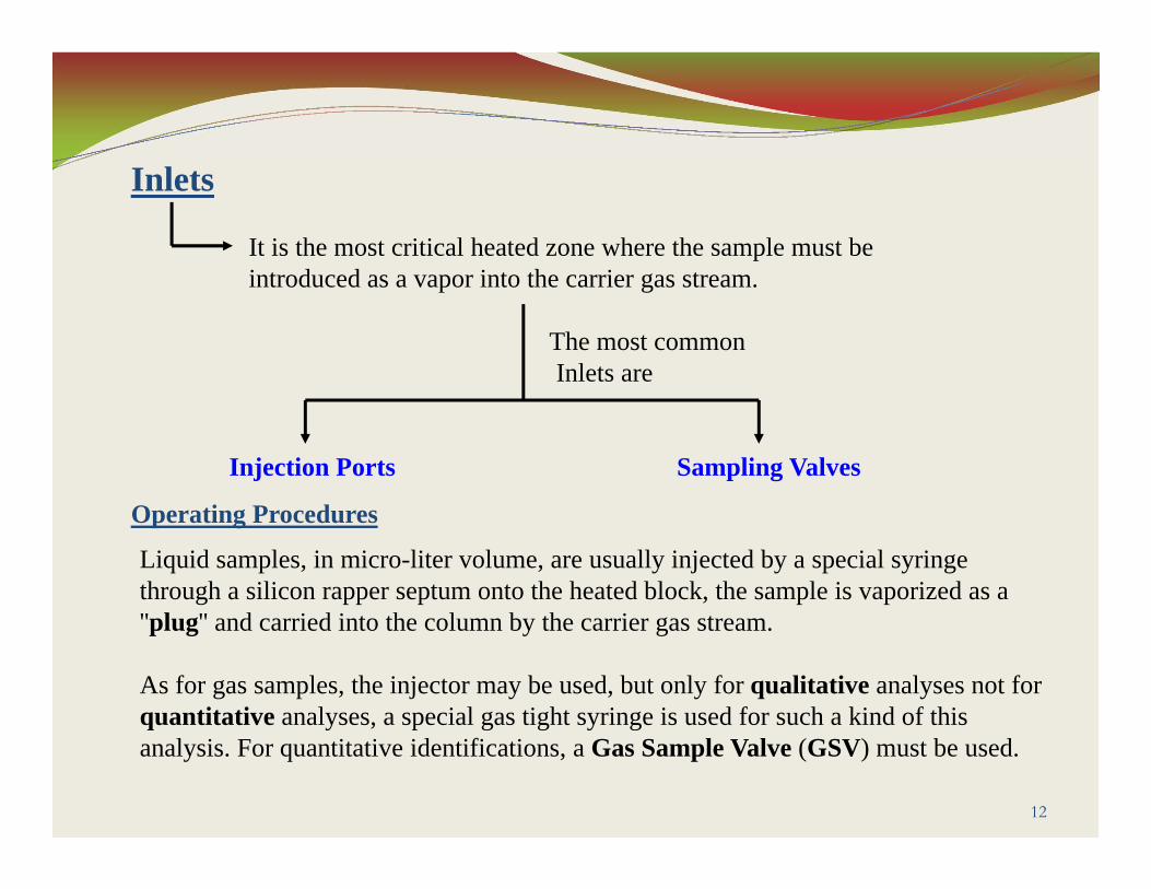
Inlets
It is the most critical heated zone where the sample must be introduced as a vapor into the carrier gas stream.
The most common Inlets are
Injection Ports Sampling Valves
Liquid samples, in micro-liter volume, are usually injected by a special syringe through a silicon rapper septum onto the heated block, the sample is vaporized as a ''plug'' and carried into the column by the carrier gas stream.
As for gas samples, the injector may be used, but only for qualitative analyses not for quantitative analyses, a special gas tight syringe is used for such a kind of this analysis. For quantitative identifications, a Gas Sample Valve (GSV) must be used.
Operating Procedures

13
A. Injection Ports
(a) Handle gas or liquid samples.(b) Often heated to vaporize liquid samples.(c) The design and choice of injection ports
depends on the column
Diameter Type
Note:Liquid or gas syringes are used to inject the sample through a septum into the carrier gas stream.
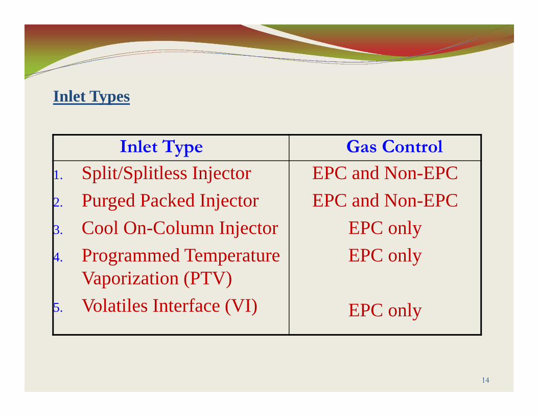
Inlet Type Gas Control
1. Split/Splitless Injector2. Purged Packed Injector3. Cool On-Column Injector4. Programmed Temperature
Vaporization (PTV)5. Volatiles Interface (VI)
EPC and Non-EPCEPC and Non-EPC
EPC onlyEPC only
EPC only
14
Inlet Types
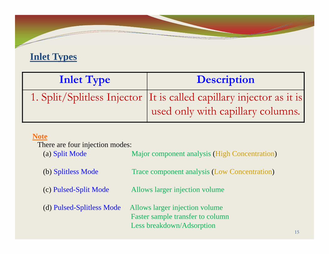
Inlet Type Description
1. Split/Splitless Injector It is called capillary injector as it is used only with capillary columns.
15
Inlet Types
NoteThere are four injection modes:
(a) Split Mode Major component analysis (High Concentration)
(b) Splitless Mode Trace component analysis (Low Concentration)
(c) Pulsed-Split Mode Allows larger injection volume
(d) Pulsed-Splitless Mode Allows larger injection volumeFaster sample transfer to columnLess breakdown/Adsorption
16
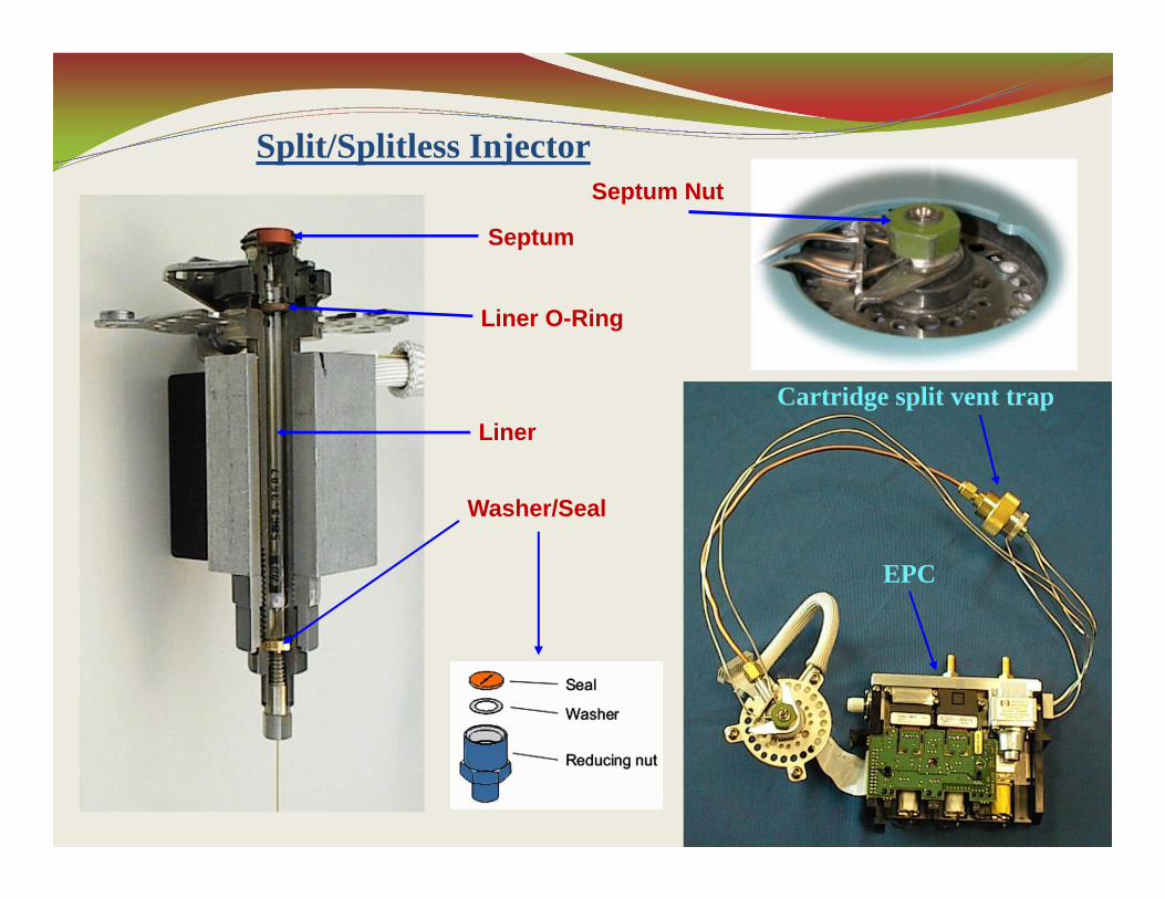
Split/Splitless Injector
Septum
Liner O-Ring
Liner
Washer/Seal
Septum Nut
Cartridge split vent trap
EPC
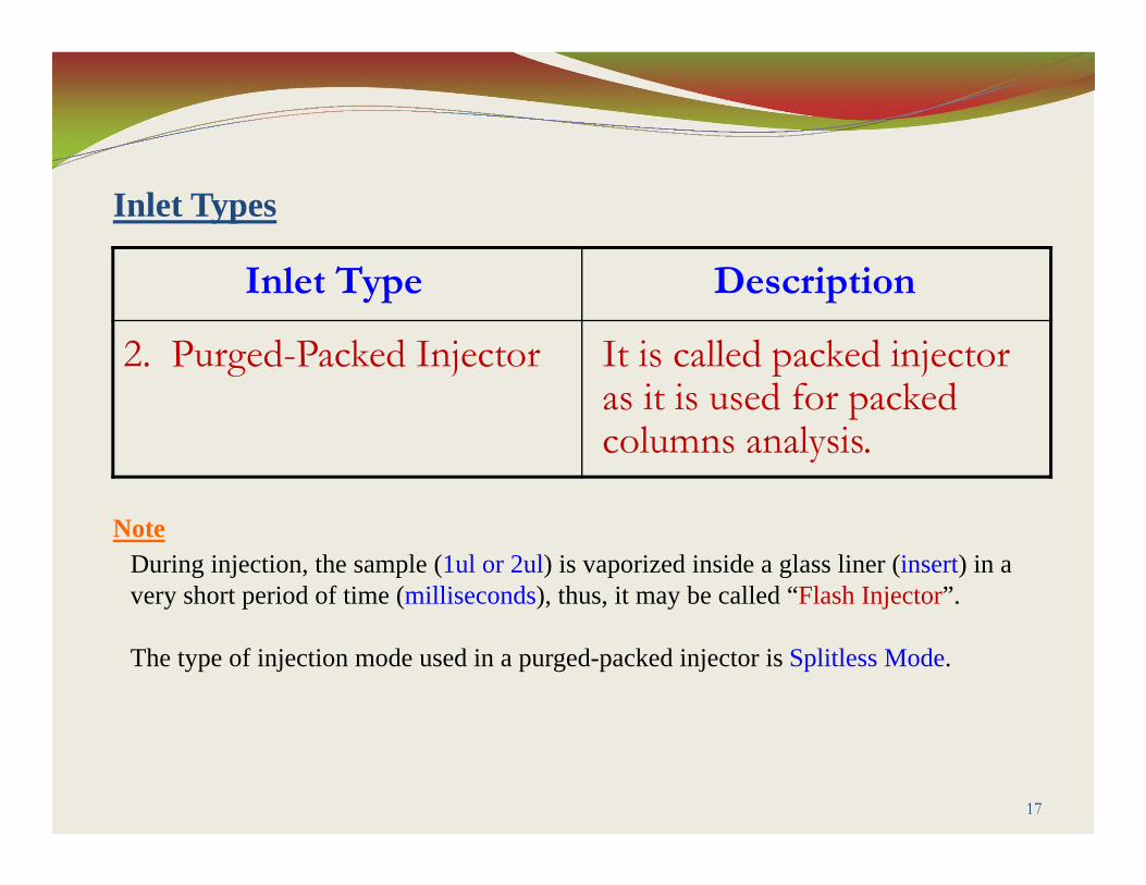
Inlet Type Description
2. Purged-Packed Injector It is called packed injectoras it is used for packedcolumns analysis.
17
Inlet Types
NoteDuring injection, the sample (1ul or 2ul) is vaporized inside a glass liner (insert) in avery short period of time (milliseconds), thus, it may be called “Flash Injector”.
The type of injection mode used in a purged-packed injector is Splitless Mode.
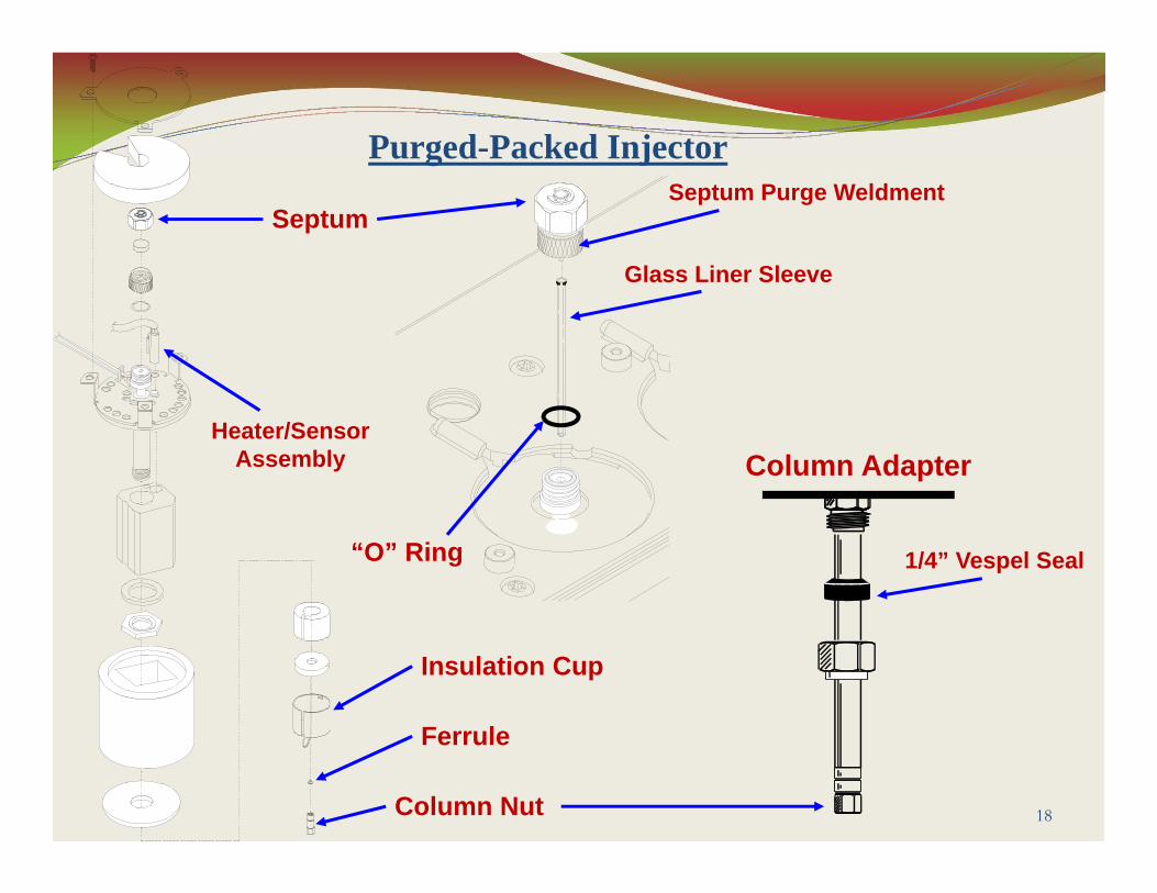
18
Purged-Packed Injector
Column Adapter
1/4” Vespel Seal
Glass Liner Sleeve
Septum Purge Weldment
Column Nut
Ferrule
Heater/SensorAssembly
“O” Ring
Septum
Insulation Cup

Inlet Type Description
3. Cool On-Column Injector
It is called on-column injector as the sample is injected and deposited directly into the column as liquid. When the sample components are thermally unstable and high sensitive is required.
19
Inlet Types
NoteMost widely used applications in Environmental.
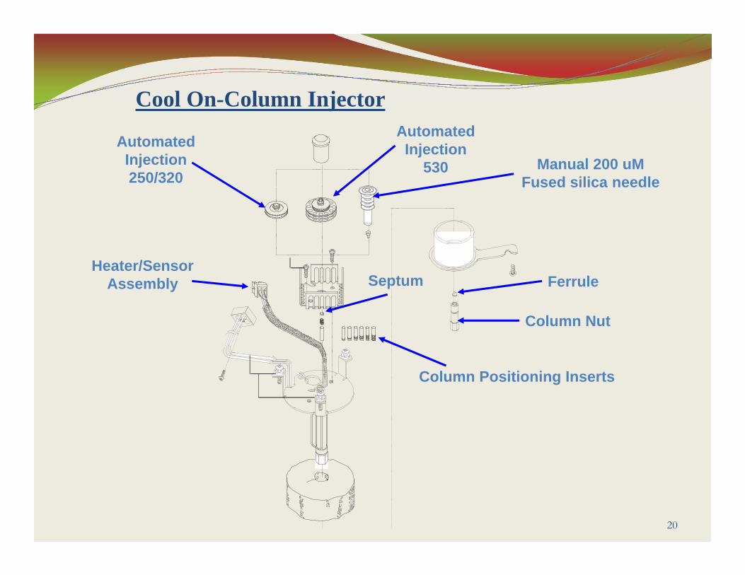
20
Cool On-Column Injector
Heater/SensorAssembly Septum
Column Positioning Inserts
Column Nut
Ferrule
AutomatedInjection250/320
AutomatedInjection
530 Manual 200 uMFused silica needle
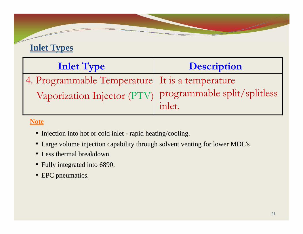
Inlet Type Description4. Programmable Temperature
Vaporization Injector (PTV)It is a temperature programmable split/splitlessinlet.
21
Inlet Types
Note
Injection into hot or cold inlet - rapid heating/cooling.Large volume injection capability through solvent venting for lower MDL'sLess thermal breakdown.Fully integrated into 6890.EPC pneumatics.
22
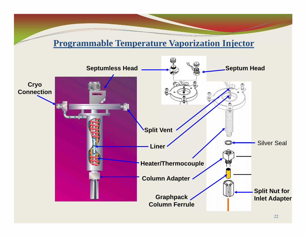
Programmable Temperature Vaporization Injector
Cryo Connection
Septumless Head Septum Head
Split Vent
Liner
Heater/Thermocouple
Column Adapter
Graphpack Column Ferrule
Silver Seal
Split Nut for Inlet Adapter

Inlet Type Description
5. Volatiles Interface Injector(VI)
It is an ideal inlet for Purge & Trap, Headspace, Thermal Desorption, or other gas injection devices.
23
Inlet Types
Note• Very Inert.• Very small internal volume (35ul)• Low split ratio or direct injection for high sensitivity.• EPC control from GC keyboard or ChemStation.
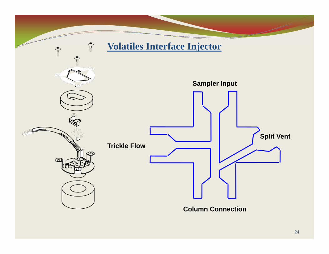
24
Sampler Input
Trickle FlowSplit Vent
Column Connection
Volatiles Interface Injector

25
GC Electronic Pneumatic Control (EPC)
Capillary Inlet EPC Module

Electronic Pneumatic ControlCapillary column (Constant Column + Makeup Flow Mode)
26
Inlet Pressure (measured/controlled)
Oven Temperature
Actual Column Flow
Constant Inlet Pressure
Makeup Gas Flow Rate
Makeup gas is programmed during run to compensate for decreasing column flow
Net carrier flow (Column + Makeup) is then constant during the GC analysis
Important for detectors that are flow dependant - such as TCD/NPD/ECD

To Convert To Multiply By
1. Psi
2. Bar
3. kPa
BarkPaPsikPaPsiBar
0.0689476 6.89476 14.5038
100 0.145038
0.01
27
Septum Purge
The septum purge line is near the septum where the sample is injected. A small amount of carrier gas exists through this line to sweep out any bleed.
Each inlet has a different septum purge flow. The GC automatically sets the purge flow for EPC inlets, but you can measure it from the septum purge vent at the flow manifold if you like.

Inlet Carrier Septum Purge
(ml/min)
1. Split/Splitless
1. Purged-Packed
2. Cool On-Column
He, N2, Ar/5%Me
H2
All
He, N2, Ar/5%Me
H2
3
6
1 to 3
15
30
28
Septum Purge Flows

Inlet Carrier Septum Purge
(ml/min)
4. Programmed Temp.
Vaporization (PTV)
5. Volatiles Interface (VI)
He, N2, Ar/5%Me
H2
He, N2, Ar/5%Me
H2
3
6
3
6
29
Septum Purge Flows
30
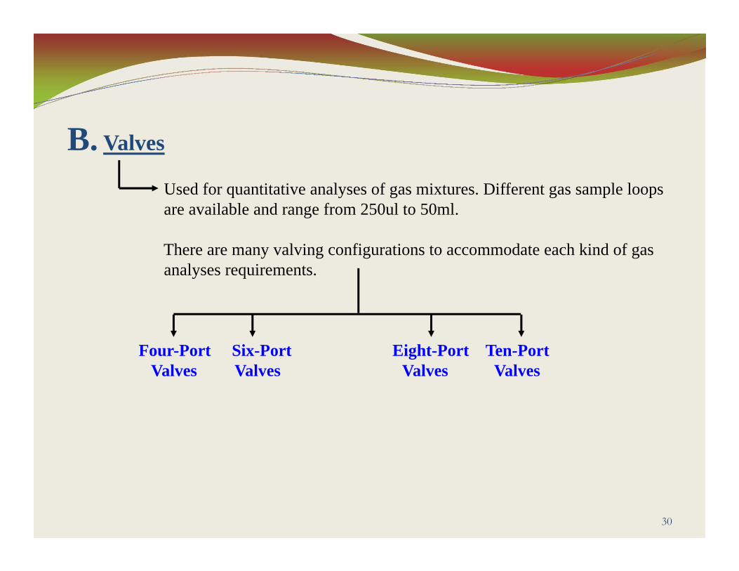
B. Valves
Used for quantitative analyses of gas mixtures. Different gas sample loops are available and range from 250ul to 50ml.
There are many valving configurations to accommodate each kind of gasanalyses requirements.
Four-Port Six-Port Eight-Port Ten-Port Valves Valves Valves Valves
3. Columns
31
32
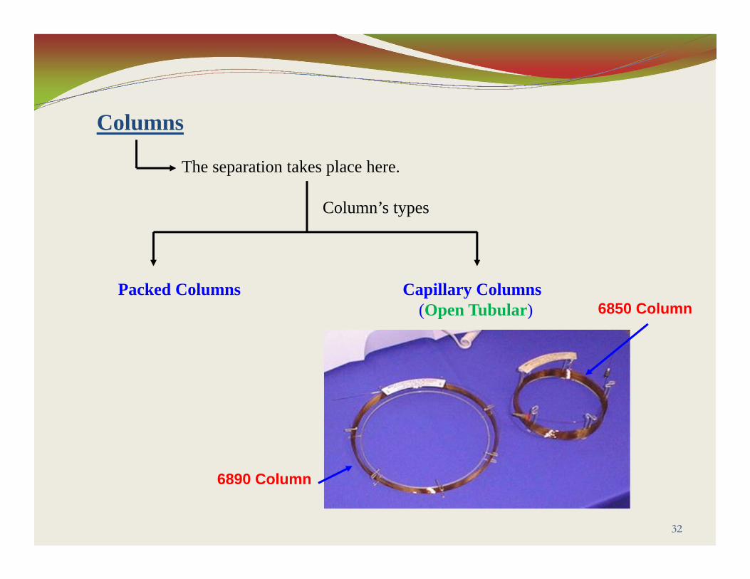
Columns
The separation takes place here.
Column’s types
Packed Columns Capillary Columns(Open Tubular)
6890 Column
6850 Column
33
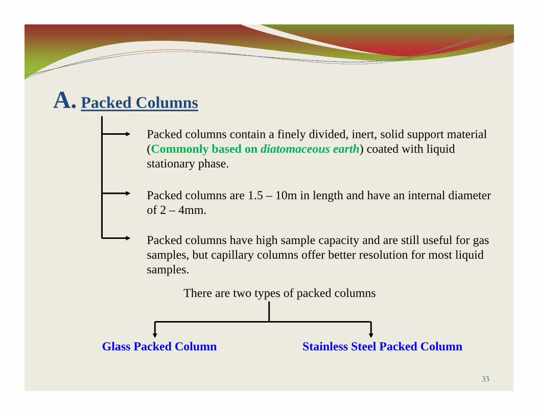
A. Packed Columns
Packed columns contain a finely divided, inert, solid support material (Commonly based on diatomaceous earth) coated with liquid stationary phase.
Packed columns are 1.5 – 10m in length and have an internal diameter of 2 – 4mm.
Packed columns have high sample capacity and are still useful for gas samples, but capillary columns offer better resolution for most liquid samples.
There are two types of packed columns
Glass Packed Column Stainless Steel Packed Column

34
B. Capillary Columns
Capillary columns is an open tube with the stationary phase coated on its inside surface. There is no packing.
Capillary columns have an internal diameter of a few tenths of a millimeter.
Capillary columns require smaller samples than packed columns.
There are two types of capillary columns
Wall-Coated Open Support-Coated Open Tubular (WCOT) Tubular (SCOT)

35
I. Wall-Coated Open Tubular (WCOT)
Consists of a capillary tube whose walls are coated with liquid stationary phase.
II. Support-Coated Open Tubular (SCOT)
The inner wall of the capillary is lined with a thin layer of support material such as diatomaceous earth, onto which the stationary phase has been absorbed.
Note• SCOT columns are generally less efficient than WCOT columns.• Both types of capillary columns are more efficient than packed columns.• In 1979, a new type of WCOT column was devised, the Fused Silica Open Tubular (FSOT) column.
36
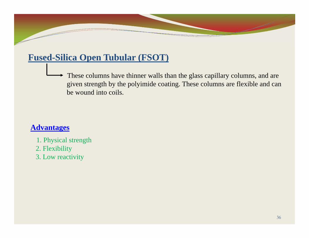
Fused-Silica Open Tubular (FSOT)
These columns have thinner walls than the glass capillary columns, and are given strength by the polyimide coating. These columns are flexible and can be wound into coils.
Advantages1. Physical strength2. Flexibility3. Low reactivity
37
The Column
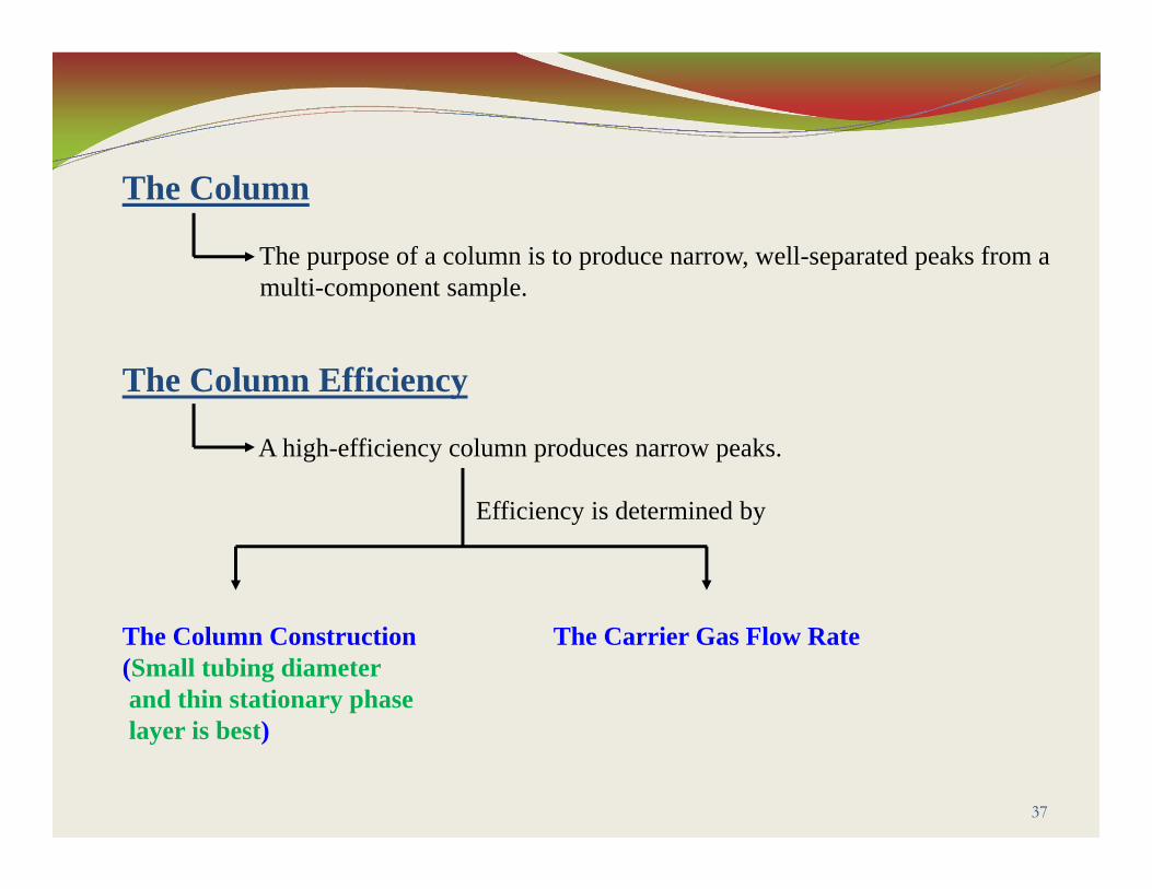
The purpose of a column is to produce narrow, well-separated peaks from a multi-component sample.
The Column Efficiency
A high-efficiency column produces narrow peaks.
Efficiency is determined by
The Column Construction The Carrier Gas Flow Rate(Small tubing diameter and thin stationary phase layer is best)

38
The Column Selectivity
This is less clearly defined property of the stationary phase.
Essentially, it is how well a phase differentiates between two compounds.
Low Selectivity High Selectivity(They elute together) (The peaks separates)
39
Column Temperature
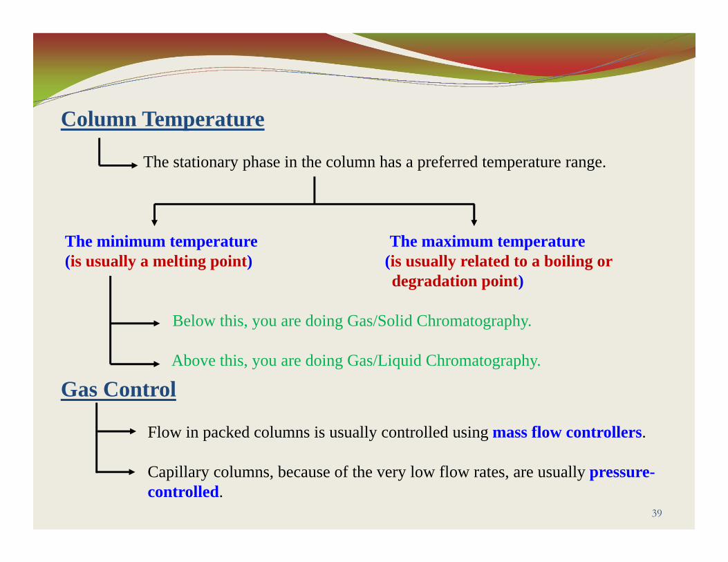
The stationary phase in the column has a preferred temperature range.
The minimum temperature The maximum temperature(is usually a melting point) (is usually related to a boiling or
degradation point)
Below this, you are doing Gas/Solid Chromatography.
Above this, you are doing Gas/Liquid Chromatography.
Gas Control
Flow in packed columns is usually controlled using mass flow controllers.
Capillary columns, because of the very low flow rates, are usually pressure-controlled.
4. Oven
40
41
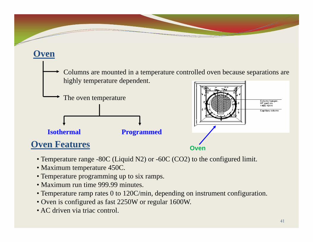
Oven
Columns are mounted in a temperature controlled oven because separations are highly temperature dependent.
The oven temperature
Isothermal Programmed
Oven
• Temperature range -80C (Liquid N2) or -60C (CO2) to the configured limit.• Maximum temperature 450C.• Temperature programming up to six ramps.• Maximum run time 999.99 minutes.• Temperature ramp rates 0 to 120C/min, depending on instrument configuration.• Oven is configured as fast 2250W or regular 1600W.• AC driven via triac control.
Oven Features

42
A. Isothermal Oven
This is the simplest way to run the oven.
The oven remains at the same temperature throughout the analysis.
Advantages1. The oven is always ready for a sample analysis.2. There is no recovery time between analysis.
Disadvantages1. Samples with a wide range of component times take a long time
to run.
43
B. Programmed Oven
The oven temperature changes, usually upward during the analysis.
Advantages1. Analysis time is reduced.2. Peak shapes are constant throughout the run, making detection and
measurement easier.
Disadvantages1. Components are subjected to higher temperatures than with an isothermal
oven. This could cause degradation of sensitive components.
2. The oven must cool to the starting temperature.
5. Detectors
44

45
Detectors
It is a heated zone, which is located at the exit of the separation column, which senses the presence of the individual components as they leave the column.
Universal Detectors Selective Detectors
There are three major response characteristics of detectors:1. Sensitivity2. Selectivity3. Dynamic Range
Detectors are classified as
46
SensitivityIt is the response per amount of sample, that is the slope of the response/amount curve.
SelectivityIt is a measure of which categories of compounds will give a detector response.
Dynamic RangeIt is the range of sample concentrations for which the detector can provide accurate quantization.

47
The Gas Chromatography (GC) has several detector systems available:1. Flame Ionization Detector (FID)2. Thermal Conductivity Detector (TCD)3. Nitrogen-Phosphorous Detector (NPD)4. Flame Photometric Detector (FPD)5. Electron Capture Detector (ECD)/ Micro-Cell Electron Capture Detector (uECD)6. Mass Spectrometer Detector (MSD)
Multiple Detectors
Detectors can be classified also as:
Destructive Non-destructiveDetectors Detectors

Detector Selectivity Delectability Dynamic Range
1. FID Most organic compounds
100pg 10^7
2. TCD Universal 1ng 10^7
3. NPD Nitrogen & Phosphorous in
compounds
10pg 10^6
4. FPD Sulphur, Phosphorous, tin, boron, arsenic,
germanium, selenium, chromium
100pg 10^3
5. ECD/uECD Halides, nitrates, nitriles, peroxides, anhydrides,
organometallics50fg 10^5
48
49
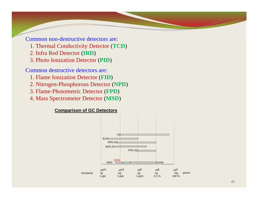
Common non-destructive detectors are:1. Thermal Conductivity Detector (TCD)2. Infra Red Detector (IRD)3. Photo Ionization Detector (PID)
Common destructive detectors are:1. Flame Ionization Detector (FID)2. Nitrogen-Phosphorous Detector (NPD)3. Flame-Photometric Detector (FPD)4. Mass Spectrometer Detector (MSD)
Comparison of GC Detectors
MSD
FPD (S)NPD (P)
NPD (N)ECD
FID
10 10 10 10 10grams
-15 -12 -9 -6 -3fg pg ng ug mg
1 ppt 1 ppb 1 ppm 0.1 % 100 %Sensitivity
(SIM)(SCAN)
50
Makeup Gas Flow
Makeup gas enters the detector close to the end of the column.
Its purpose is to speed the peaks through the detector, especially with capillary columns, so that the peak separation achieved by the column is not lost through remixing in the detector.

6. Data Handling System
51
52
Data Handling
The signal of a detected peak which comes out from the detector can be measured in volts (or millivolts), so we can use a voltmeter to see that signal, of course this kind of measurements is not practical because we need a documented data sheet includes the plotted chromatogram and the area counts (integration) of each peak in that chromatogram in order to make handling with these data. The data handling device is responsible for that.
The data handling device output may be a plotted chromatogram only (Recorder), or a plotted chromatogram with accurate counts of retention time (RT) and area for each peak (Integrator).
53
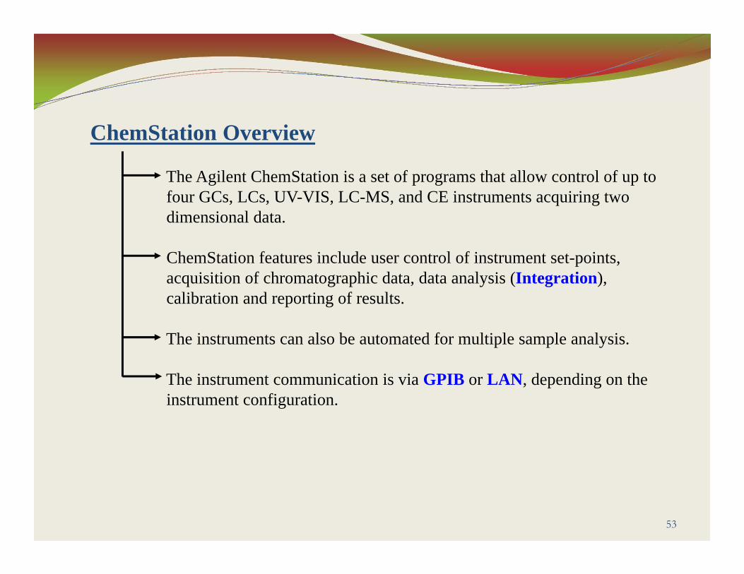
ChemStation Overview
The Agilent ChemStation is a set of programs that allow control of up to four GCs, LCs, UV-VIS, LC-MS, and CE instruments acquiring two dimensional data.
ChemStation features include user control of instrument set-points, acquisition of chromatographic data, data analysis (Integration), calibration and reporting of results.
The instruments can also be automated for multiple sample analysis.
The instrument communication is via GPIB or LAN, depending on the instrument configuration.
54
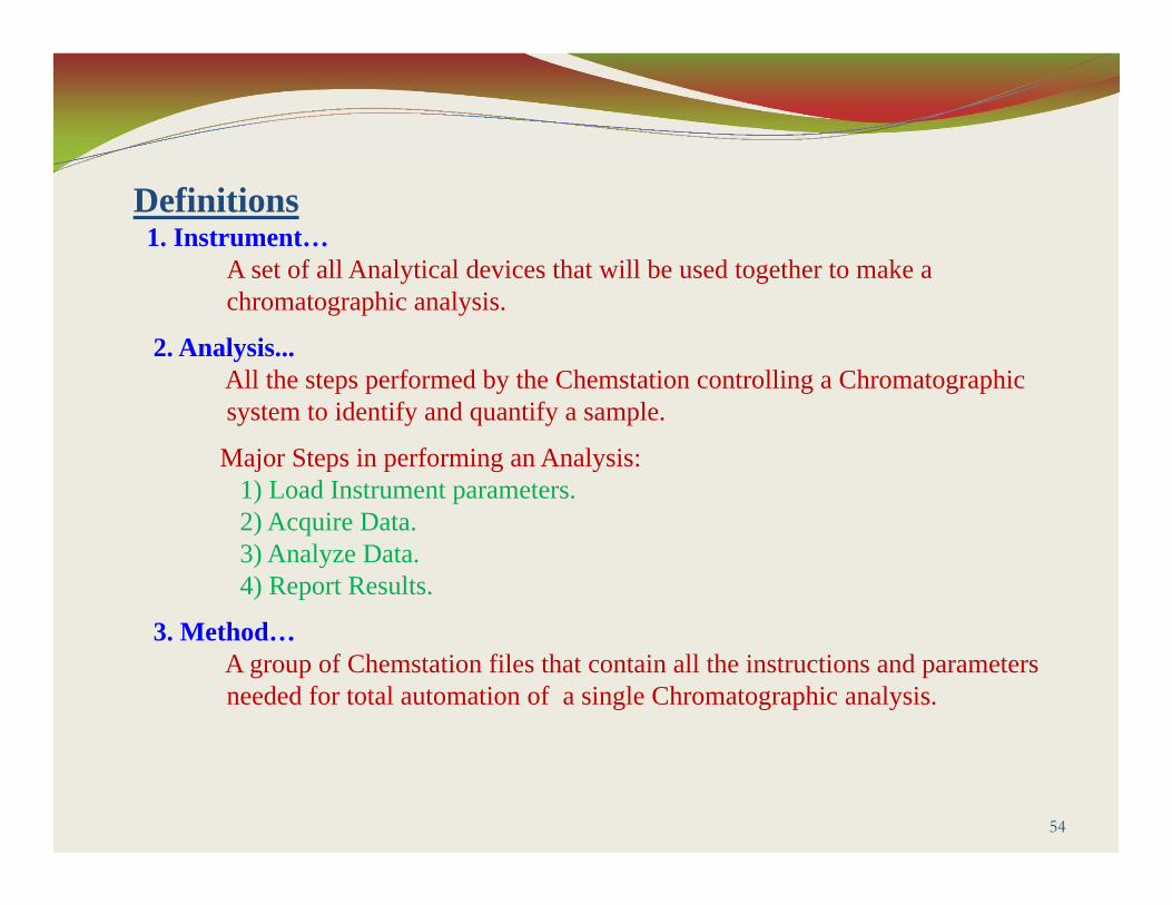
Definitions1. Instrument…
A set of all Analytical devices that will be used together to make achromatographic analysis.
2. Analysis...All the steps performed by the Chemstation controlling a Chromatographic system to identify and quantify a sample.
Major Steps in performing an Analysis:1) Load Instrument parameters.2) Acquire Data.3) Analyze Data.4) Report Results.
3. Method…A group of Chemstation files that contain all the instructions and parameters needed for total automation of a single Chromatographic analysis.

The END
55
Prepared ByMohamed Salama