gateway vega bs
TRANSCRIPT

www.vega-absolute.ru
GATEWAY
VEGA BS
USER MANUAL

Vega BS / User Manual
2
Revision 23 of 14 September 2021
CONTENT
INTRODUCTION ......................................................................................................................................................................... 3 1 DESCRIPTION AND OPERATION ......................................................................................................................................... 4 2 SPECIFICATION ....................................................................................................................................................................... 5 3 OPERATION .............................................................................................................................................................................. 7
Contacts ................................................................................................................................................................................... 8
Input and output interfaces .................................................................................................................................................. 9
SIM card installation at the BS-2 and BS-2.2 ................................................................................................................... 10
Control instruments – buttons and switches ................................................................................................................. 12
Indication ............................................................................................................................................................................... 13 4 CONFIGURING OF THE GATEWAY WITH WEB-INTERFACE ........................................................................................ 14
Interface launch – the operation begining ..................................................................................................................... 14 5 CONFIGURING OF THE GATEWAY WITHOUT WEB-INTERFACE ................................................................................ 20
Gateway connecting to the computer – the operation begining .............................................................................. 20
Packet forwarder updating to 4.0.1 version (Only for BS-1 and BS-2) ...................................................................... 28
Configuration of a static IP-adress for the gateway (For BS-1.2 and BS-2.2) ........................................................... 30
Configuration of a static IP-adress for the gateway (For BS-1 and BS-2) ................................................................. 33
Gateway setting up for 3G operation ............................................................................................................................... 36 5 STORAGE AND TRANSPORTATION REQUIREMENTS ................................................................................................... 38 6 CONTENT OF THE PACKAGE ............................................................................................................................................. 39 7 WARRANTY ............................................................................................................................................................................. 40 Appendix – recommendations for working with gateway .............................................................................................. 42
Antenna mounting recommendations ............................................................................................................................. 42
Recommendations for gateway using in white IP net .................................................................................................. 43

Vega BS / User Manual
3
Revision 23 of 14 September 2021
INTRODUCTION
This manual is designed for Vega BS-1, Vega BS-2, Vega BS-1.2 and Vega BS-2.2
gateways (hereinafter – the gateway) manufactured by Vega-Absolute OOO and provides
information on powering and activation procedure, control commands and functions of the
gateway.
Gateways can be supplied without software by request
This manual is targeted at specialists familiar with installation work fundamentals for
electronic and electrical equipment.
The gateway shall be installed and adjusted by qualified specialists to ensure proper operation of the device.
Vega-Absolute OOO reserves the right to make changes to the manual related to the
improvement of equipment and software, as well as to eliminate typos and inaccuracies,
without prior notice.

Vega BS / User Manual
4
Revision 23 of 14 September 2021
1 DESCRIPTION AND OPERATION
Vega BS gateway is designed to deploy LoRaWAN network within 863-870 MHz
frequency band.
The gateway operates with Linux operating system and is supplied with pre-installed
Packet forwarder software.
The gateway is powered and communicates with the server via the Ethernet channel.
The device is configured through Ethernet either via web-interface or via SSH protocol
with any terminal program (e.g. PuTTY).
Vega BS-2 and Vega BS-2.2 have an additional 3G-module for communication channel
and GPS/GLONASS-module for gateway positioning, and internal clock synchronizing with
navigation-satellites signals.
IP65 IP67

Vega BS / User Manual
5
Revision 23 of 14 September 2021
2 SPECIFICATION
Model BS-1 BS-1.2 BS-2 BS-2.2
MAIN
GPS/GLONASS module no yes
3G modem no yes
Server communication link
Ethernet 10/100 Base-T Ethernet 10/100 Base-T, GSM 3G1
Operating system Linux
USB-port yes
Operating t t
-40…+70 °С
LORAWAN®
Number of LoRa channels
8
Frequency band 863-870 MHz
Power output up to 500 mW
Antenna connector SMA N-Type female SMA N-Type female
Radio coverage in restrained urban conditions
up to 5 km
Radio coverage within line of sight
up to 15 km
1 3G-modem used in BS-2.2 supports the following frequency: Dual-Band UMTS (WCDMA/FDD) 900 and 2100 MHz Dual-Band GSM 900 and 1800 MHz

Vega BS / User Manual
6
Revision 23 of 14 September 2021
Model BS-1 BS-1.2 BS-2 BS-2.2
POWER
Power consumption up to 10 W
Power supply Passive POE 4,5(+) 7,8(-) 15 W
CASE
Housing dimensions 165 х 110 х 40 190 х 183 х 75 165 х 110 х 40 190 х 183 х 75 Ingress protection
IP65 IP67 IP65 IP67
Mounting mast supports

Vega BS / User Manual
7
Revision 23 of 14 September 2021
3 OPERATION
The gateway terminal board has control and indication instruments, input and output
interfaces. Detailed information see below.
Fig. 3.1. Control and indication instruments, input and output interfaces.
1 – mini USB-port for connection to a computer
2 – USB-host for connection of external devices
3 – /Spare/
4 – gateway reset button
5 – service DIP-switches
6 – performance indicators of various systems
7 – micro SD-card connector
8 – Ethernet-cable connector
9 – additional power connector (optional)

Vega BS / User Manual
8
Revision 23 of 14 September 2021
CONTACTS
Fig. 3.2. Order of contacts in the connectors.
The gateway is connected to the network with an 8-core network cable (twisted pair)
through connector on the board (fig. 3.1 (8)). Cable shall be crimped in compliance with Т568А
and Т568B standards. Contacts are numerated from 1 to 8 in order right-to-left.
Colors are shown for cable T568B:
Contact number
Color Designation
1 Orange-and-white TD+ signal 2 Orange TD- signal 3 Green-and-white RD+ signal 4 Blue Power 5 Blue-and-white Power 6 Green RD- signal 7 Brown-and-white Ground 8 Brown Ground

Vega BS / User Manual
9
Revision 23 of 14 September 2021
There is an additional power connector on the board (fig. 3.1 (9)). It can be connectable
only when power contacts 4, 5 and 7, 8 in the network cable are disabled. Permissible power
voltage is 12-48 V. Minimum power is 20 W.
INPUT AND OUTPUT INTERFACES
The gateway has a mini-USB-port for connecting to a computer and working via the SSH
protocol (Fig. 3.1 (1)), and a USB-host for connecting of external devices via a USB cable (Fig. 3.1
(2)). There is a slot on the board for a SD card (fig. 3.1 (7)).
In addition, there is a connector on the gateway housing for connecting of the antenna
supplied with the device: SMA or N-connector.
It’s important to place the gateway antenna properly for high-quality signal reception.
To find out an antenna installing recommendations, see the Appendix.
SMA N

Vega BS / User Manual
10
Revision 23 of 14 September 2021
SIM CARD INSTALLATION AT THE BS-2 AND BS-2.2
Vega BS-2 and Vega BS-2.2 gateways include a GSM module, which is placed on the
main board.
BS-2
BS-2.2

Vega BS / User Manual
11
Revision 23 of 14 September 2021
The SIM slot is located on the back side of the module. To install the SIM card, you must
disconnect the GSM module from the main board and turn it over.
You need to insert the SIM card of the micro-SIM format into the slot, and then return
the GSM module on its own place.

Vega BS / User Manual
12
Revision 23 of 14 September 2021
CONTROL INSTRUMENTS – BUTTONS AND SWITCHES
There are two buttons on the gateway board. One button is reserved for further
developments (Fig. 3.1 (3)). Press the other button (Fig. 3.1 (4)) for the gateway instantaneous
rebooting.
In addition, there are DIP-switches (Fig. 3.1 (5)) on the board used to select the download
option of the firmware image: from internal memory, from the SD card or via mini-USB from
the computer. The switches are only for service conditions. In operating mode, only switches
3 and 4 shall be enable, see fig. 3.3.
Fig. 3.3. Operating position of DIP-switche.
Vega BS / User Manual
13
Revision 23 of 14 September 2021
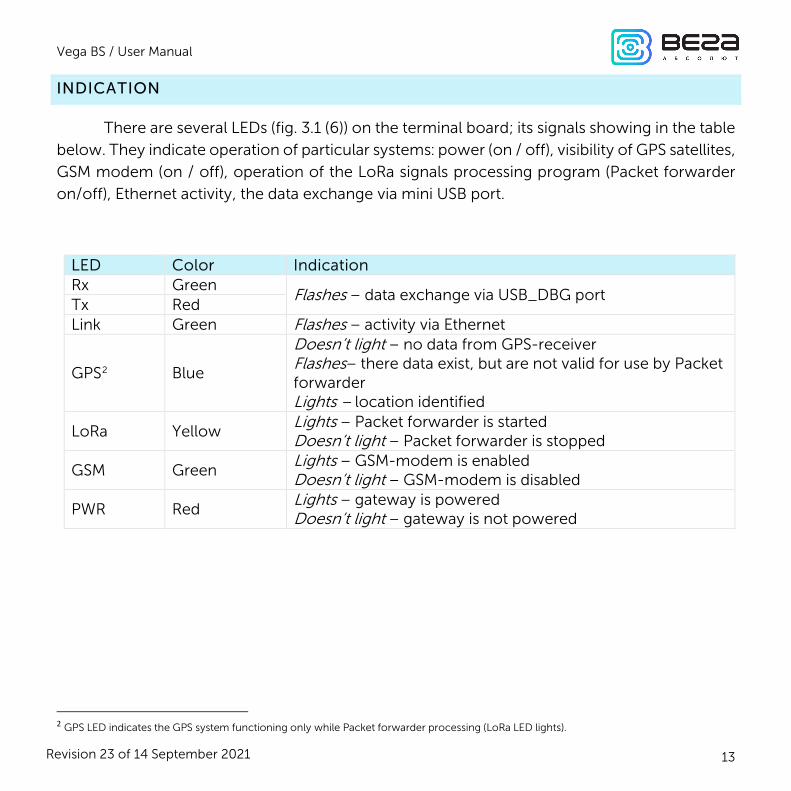
INDICATION
There are several LEDs (fig. 3.1 (6)) on the terminal board; its signals showing in the table
below. They indicate operation of particular systems: power (on / off), visibility of GPS satellites,
GSM modem (on / off), operation of the LoRa signals processing program (Packet forwarder
on/off), Ethernet activity, the data exchange via mini USB port.
LED Color Indication Rx Green
Flashes – data exchange via USB_DBG port Tx Red Link Green Flashes – activity via Ethernet
GPS2 Blue
Doesn’t light – no data from GPS-receiver Flashes– there data exist, but are not valid for use by Packet forwarder Lights – location identified
LoRa Yellow Lights – Packet forwarder is started Doesn’t light – Packet forwarder is stopped
GSM Green Lights – GSM-modem is enabled Doesn’t light – GSM-modem is disabled
PWR Red Lights – gateway is powered Doesn’t light – gateway is not powered
2 GPS LED indicates the GPS system functioning only while Packet forwarder processing (LoRa LED lights).

Vega BS / User Manual
14
Revision 23 of 14 September 2021
4 CONFIGURING OF THE GATEWAY WITH WEB-INTERFACE
INTERFACE LAUNCH – THE OPERATION BEGINING
If gateway is made after the 1st December 2019, then it has a pre-install web-interface – see description in part 4, also it still has an option of configuring via terminal program – see part 5. If gateway was made early, then it has not a web-interface, but you still can configure it via terminal program – see part 5 – or make a request for ‘how to install the gateway web-interface’ manual.
Interface software consist of two parts:
1. Server’s API “BS-Dashboard” which (in depending on received data) transmits current
settings, device information and saved new settings at the device memory. API «BS-
Dashboard» is available on the port 3001 by default.
2. Client’s web-application operating with server’s API “BS-Dashboard” – is developed
for visual displaying data, for validation of changes and for sending the settings to save at the
device. Client’s web-application is available on the port 80.
“BS-Dashboard” launched by the pressing the button (see fig. 3.1 (3)) on the gateway
board. It may be changed in the settings. After holding the button in a pressed state during more
than 6 seconds the launch begins, which may be continuing about 1 or 2 minutes in depending
on the device loading.
For entering to a client’s web-application IP-address of the gateway is needed. You can
find out it with terminal program (for example, with a free PuTTY program). Part 5 describes in
detail how to connect to a gateway with a terminal program. You should enter the command
ifconfig in terminal window.

Vega BS / User Manual
15
Revision 23 of 14 September 2021
The next step is to open a browser and enter IP-address in the address bar. If the “BS-
Dashboard” server is launched successfully then the authorization page for login into the
client’s web-application will appear.
If there is no connection to Web-interface and authorization page is not appearing, then you need to add port number 80 to IP address of the gateway in the address bar. It may look like this, for example: http://192.168.1.228:80

Vega BS / User Manual
16
Revision 23 of 14 September 2021
After entering login and password of the gateway (root and temppwd by default)
gateway’s interface page appears.
At the top of the page is the name of the menu section in which you are currently.

Vega BS / User Manual
17
Revision 23 of 14 September 2021
If the interface is launched by pressing the button, then when the gateway is restarted, it
will become unavailable again. For the interface to always be available, you need to change the
server startup settings. To do this, go to the “Settings” menu, then “Manager Settings” and in the
“BS-Dashboard Server Startup Method” field change the value to “Always On”. After that, be
sure to click the “Save” button so that the settings go to the gateway.

Vega BS / User Manual
18
Revision 23 of 14 September 2021
The main features of working with the interface:
1. If you change something in any menu, and then proceed to the next, these changes
are saved in the client, but not saved on the gateway, and the edit icon appears in the
menu block, where the unsaved changes remained.

Vega BS / User Manual
19
Revision 23 of 14 September 2021
2. To apply the settings changes at the gateway, you always need to click the "Save"
button.
3. If you click the “Reset these settings” button, then all unsaved changes will be lost.
4. The buttons "Save" and "Reset settings" apply only to the group of parameters under
which they are directly located.
5. The “Expert” mode allows you to see additional settings in the sections “Frequency
plans”, “3G settings”, “Network settings”, “Settings” (only the “Manager settings”
subsection) and “Actions”.

Vega BS / User Manual
20
Revision 23 of 14 September 2021
5 CONFIGURING OF THE GATEWAY WITHOUT WEB-INTERFACE
GATEWAY CONNECTING TO THE COMPUTER – THE OPERATION BEGINING
If gateway is made after the 1st December 2019, then it has a pre-install web-interface – see description in part 4, also it still has an option of configuring via terminal program – see part 5. If gateway was made early, then it has not a web-interface, but you still can configure it via terminal program – see part 5 – or make a request for ‘how to install the gateway web-interface’ manual.
Connection is possible, for example, with a free PuTTY program. There are two ways of
connection to the gateway – via a serial port or SSH.
1. Connection via a serial port
In case of a serial port, connect the gateway to a personal computer with a mini-USB
connector by a cable. On the board, the required port designating as USB_DBG (Fig. 3.1 (1)).
Next, connect to a virtual COM port by installing the driver for MCP2200. "Ports (COM and
LPT)" menu appears at the device manager.
Search “USB Serial Port” in the “Ports” menu and see its number.

Vega BS / User Manual
21
Revision 23 of 14 September 2021

Vega BS / User Manual
22
Revision 23 of 14 September 2021
Open PuTTY, select Serial, enter number of the gateway virtual COM-port and speed
(115200) in the corresponding fields.
Press “Open” button.

Vega BS / User Manual
23
Revision 23 of 14 September 2021
2. Connection via SSH
In case of SSH, select SSH connection in the PuTTY dialog box, enter the device's IP-
address and port 22. By default, the device obtains an IP-address via DHCP when connected
via Ethernet.
Press “Open” button.
After connecting to the gateway by one of the methods, PuTTY terminal window
appears where you should to enter login and password. By default, login root and password
temppwd (symbols not displaying while entering the password) are used for connection to

Vega BS / User Manual
24
Revision 23 of 14 September 2021
the gateway. At the first connection, it is recommend to change the password for individual
access.
Now the configuration can be carrying out.
Packet forwarder starts automatically when the system starts. Before the gateway
configuring, stop Packet forwarder by entering command:
/etc/init.d/lora_watchdog stop

Vega BS / User Manual
25
Revision 23 of 14 September 2021
Configuration files are in the directory LoRa/packet_forwarder/lora_pkt_fwd – it may
contain frequency band, the gateway ID, IP-address and server ports settings.
global_conf.json – global configuration file;
local_conf.json – local configuration file.
Settings contained in local_conf.json file take priority over global_conf.json
Enter the command, containing the required configuration file in order to change the
settings, for example:
After all changes completed enter the command:
/etc/init.d/lora_watchdog start
Packet forwarder will automatically start with new settings.

Vega BS / User Manual
26
Revision 23 of 14 September 2021
To connect the gateway to the server, you must use the UDP port specified in the server configuration file. On the gateway, the port configuration is in the global_conf.json file
In the global_conf.json file, the UDP port settings are in the gateway_conf section,
there are server_port_up and server_port_down parameters.
In order to communicate with the server correctly, you should make sure that these
UDP port parameters correspond to those specified in the server configuration file (see details
in the «IOT Vega Server Manual»).

Vega BS / User Manual
27
Revision 23 of 14 September 2021
To replace configuration file (for example, for change frequency plan) you need to
make the following steps:
1. Go to Packet forwarder directory by the command:
cd LoRa/packet_forwarder/lora_pkt_fwd/
2. Download file with needful settings. For example, from iotvega.com the EU868
frequency plan file (following command is exactly for that file):
wget ftp://89.189.183.233:30451/RU868_global_conf.json
3. Open the old file global_conf.json by the command:
nano LoRa/packet_forwarder/lora_pkt_fwd/global_conf.json
and make a copy of the next parameters - gateway_ID, server address and port, and
then close the file.
4. Delete old file global_conf.json by the command:
rm global_conf.json
5. Make a copy of downloaded file (EU868_global_conf.json in our example) with a
new name global_conf.json by the command:
cp EU868_global_conf.json global_conf.json
6. Open file global_conf.json by the command:
nano LoRa/packet_forwarder/lora_pkt_fwd/global_conf.json
and specify saved in step 3 parameters, - gateway_ID, server address and port, and
then save and close the file.
7. Restart gateway by the command: reboot

Vega BS / User Manual
28
Revision 23 of 14 September 2021
PACKET FORWARDER UPDATING TO 4.0.1 VERSION (ONLY FOR BS-1 AND BS-2)
Packet forwarder updating through computer connection using the terminal program in
the following way:
1. After connecting to gateway, enter login and password in the PuTTY terminal
window.
2. Enter a command /etc/init.d/lora_watchdog stop – command to turn off the
internal timer.
3. Go to the root directory with the command cd ~/
Before upgrading Packet forwarder, save the settings from the files local_conf.json and global_conf.json located in ~/LoRa/packet_forwarder /lora_pkt_fwd/ for later restoration of the settings after the update
4. Delete files of the previous version of Packet forwarder by sequential introduction
of commands:
rm -r LoRa
rm LoRa.tar.gz
5. Download files of the new version of the Packet forwarder by typing at the
command line:
wget ftp://89.189.183.233:30451/LoRa_v4.0.1.tar.gz
6. Unzip the downloaded files with the command tar xf LoRa_v4.0.1.tar.gz -C ~/
7. Move downloaded files to the working directory mv ~/LoRa_v4.0.1 ~/LoRa
8. Restore settings in files local_conf.json и global_conf.json
9. If the GPS module in BS-2 has a label "MOD_EVA", then in the file global_conf.json
the option "ubx_timegps_control_enable" should be enabled, i.e.
"Ubx_timegps_control_enable": true. In other cases, when the GPS-module has
other labels, that option should be disabled, i.e. "Ubx_timegps_control_enable":
false.

Vega BS / User Manual
29
Revision 23 of 14 September 2021
10. Restart the Packet forwarder process with the command
/etc/init.d/lora_watchdog start
Update complete.

Vega BS / User Manual
30
Revision 23 of 14 September 2021
CONFIGURATION OF A STATIC IP-ADRESS FOR THE GATEWAY (FOR BS-1.2 AND
BS-2.2)
Configuration of a static IP is different for first generation gateways and second.
For the second generation (BS-1.2 and BS-2.2) configuration carrying out with the
terminal program in the following way:
1. After connecting to the gateway, enter login and password in the PuTTY terminal
window.
2. Open file nano /etc/network/interfaces. Search authorization settings in this file:

Vega BS / User Manual
31
Revision 23 of 14 September 2021
3. That are strings exactly:
4. For static IP mode, you should to remove # symbol from the 3rd to 6th strings and
specify your parameters are address, netmask and gateway.
5. Comment the 2nd string, there is result on the following screenshot (but another
addresses value):

Vega BS / User Manual
32
Revision 23 of 14 September 2021
In that example shown setting of the static IP-address 192.168.10.2 and gateway 192.168.10.1 You need to change those values to others, which are necessary to your own case
6. Type reboot in command line for gateway restarting with new settings.
7. Going back is similar.

Vega BS / User Manual
33
Revision 23 of 14 September 2021
CONFIGURATION OF A STATIC IP-ADRESS FOR THE GATEWAY (FOR BS-1 AND BS-
2)
Configuration of a static IP is different for first generation gateways and second.
For the first generation (BS-1 and BS-2) configuration carrying out with the terminal
program in the following way:
1. After connecting to the gateway, enter login and password in the PuTTY terminal
window.
2. Open file nano /etc/network/interfaces. Search authorization settings in this file:

Vega BS / User Manual
34
Revision 23 of 14 September 2021
3. Enter changes highlighted in red:
auto eth0 iface eth0 inet static
pre-up /bin/grep -v -e "ip=[0-9]\+\.[0-9]\+\.[0-9]\+\.[0-9]\+" /proc/cmdline > /dev/null address 192.168.240.252
netmask 255.255.255.0 gateway 192.168.240.1
In that example shown setting of the static IP-address 192.168.240.252 and gateway 192.168.240.1 You need to change those values to others, which are necessary to your own case
4. Open file nano link_detect.sh - then search string
if [ "$LINK_STATE" == "UP" ] ; then
Check after this string the following string is entered
if [ -n "$(cat /etc/network/interfaces | grep "iface $INTERFACE inet dhcp")" ];
then
Check before string
killall -15 lora_pkt_fwd
the following string is entered
fi
(see figure below)

Vega BS / User Manual
35
Revision 23 of 14 September 2021
5. If the strings correspond to the figure above, do not change anything. If these strings
are absent, enter them – changes are highlighted in red:
if [ "$LINK_STATE" == "UP" ] ; then if [ -n "$(cat /etc/network/interfaces | grep "iface $INTERFACE inet dhcp")" ]; then
killall -15 udhcpc udhcpc –R –t 5 –n –p /var/run/udhcpc.$INTERFACE.pid –i $INTERFACE
fi killall -15 lora_pkt_fwd
6. Enter reboot at the command line to reboot the gateway with new settings.

Vega BS / User Manual
36
Revision 23 of 14 September 2021
GATEWAY SETTING UP FOR 3G OPERATION
For setting up the gateway BS-2 please write on the e-mail [email protected] for getting instructions
Gateway BS-2.2 setting up for 3G operation using the terminal program is in the
following order:
1. Check, that in file nano /etc/wvdial.conf entered strings highlighted in red:
; Init1 = ATZ
; Init2=ATQO V1 E1 &C1 &D2 +FCLASS=0 Init1 = AT+CPIN?
Init2 = AT+CGDCONT=1,"IP","internet.beeline.ru" Modem Type = USB Modem
Baud = 460800 New PPPD = yes
Auto Reconnect = off Modem = /dev/ttyACM0
ISDN = 0 Phone = *99#
Password = beeline Username = beeline
where "internet.beeline.ru" is APN cellular operator. Change APN value according to
APN cellular operator using by the gateway.
In that example shown 3G setting for Beeline cellular operator You need to change those values to others, which are necessary to your own case

Vega BS / User Manual
37
Revision 23 of 14 September 2021
If the strings correspond to the figure above, you do not need to change anything,
except the APN. If these strings are not present, then you should to add them. At that, strings
Init1 = AT+CPIN? Init2 = AT+CGDCONT=1,"IP","internet.beeline.ru"
are entering instead string
Init = AT+CGDCONT=1,"IP","internet.beeline.ru"
The last three strings of the file specify the required dial-up phone, user name and
password (different for each cellular operator):
Phone = *99# Password = beeline Username = beeline
Password and Username fields could not be are empty, if those parameters are not used by the cellular operator, then you may to enter ‘internet’ word at both fields for example
BS-2.2 gateways are switching between Ethernet and 3G automatically
For recommendations for gateways using white IP, see Appendix.
If you use such two communication channels as Ethernet and 3G at the same time you should to remember that Ethernet has a priority for communication and 3G used as a backup option if gateway cannot communicate with the server via Ethernet

Vega BS / User Manual
38
Revision 23 of 14 September 2021
5 STORAGE AND TRANSPORTATION REQUIREMENTS
Vega BS gateways shall be stored in the original packaging in heated room at
temperatures +5 °С to +40 °С and relative humidity less than 85 %.
The gateway transportation is permissible in covered freight compartments of all types
at any distance at temperatures -40 °C to +85 °C.

Vega BS / User Manual
39
Revision 23 of 14 September 2021
6 CONTENT OF THE PACKAGE
The gateway delivered complete with:
Vega BS gateway – 1 pc.
POE-adapter– 1 pc.
Factory certificate – 1 pc.

Vega BS / User Manual
40
Revision 23 of 14 September 2021
7 WARRANTY
The manufacturer guarantees that the product complies with the current technical
documentation, subject to the storage, transportation and operation conditions specified in the
"User Manual".
The warranty period is 36 months.
The warranty period of operation is calculated from the date of sale marked in the
product factory certificate, and from the release date when such a mark is absent. During the
warranty period, the manufacturer is obliged to provide repair services or replace a failed device
or its components.
The manufacturer does not bear warranty obligations in the event of a product failure if:
the product does not have a factory certificate;
the factory certificate does not have an TCD stamp and / or there is no sticker with
information about the device;
the serial number (MAC) printed on the product differs from the serial number
(MAC) specified in the factory certificate;
the product has been subject to alterations in the design which are not provided
for in the operational documentation;
the product has mechanical, electrical and / or other damage and defects arising
from violation of the conditions of transportation, storage and operation;
the product has traces of repair outside the manufacturer's service center;
the components of the product have internal damage caused by the ingress of
foreign objects / liquids and / or natural disasters (flood, fire, etc.).
The average service life of the product is 5 years.

Vega BS / User Manual
41
Revision 23 of 14 September 2021
In the event of a warranty claim, contact the service center:
113/1, Kirova Str., Novosibirsk, 630008, Russia.
Tel.: +7 (383) 206-41-35.

Vega BS / User Manual
42
Revision 23 of 14 September 2021
APPENDIX – RECOMMENDATIONS FOR WORKING WITH GATEWAY
ANTENNA MOUNTING RECOMMENDATIONS
The Antenna included in the scope of supply has fasteners for installation on a mast
support. To ensure maximum communication range, follow the installation guidelines for the
antenna:
1. Install the antenna outside, preferably on the roof of the building (the higher - the
better, depending on the surrounding buildings). Installing the antenna in the room significantly
weakens the sensitivity of the antenna.
2. The installation site shall be as far as possible from the cellular antennas. Antenna
tuning requires the maximum distance from other antennas. After tuning and testing, antenna
can be brought back closer to the cellular antennas, if the quality of the communication is
satisfactory.
3. The antenna shall not stand in the close proximity to obstacles (about 2 meters from
railing, walls, etc.). The sensitivity towards the obstacle weakens.
4. The gateway shall be installed in the close proximity to the antenna – at the length of
the antenna coaxial conductor. Increase of the cable length between the antenna and the
gateway will result in a loss of antenna sensitivity.
For example, 25 meters of RG-58 cable attenuate the signal by 14 dBm, i.e. if transmission power is 14 dBm (25mW), the power on the antenna will be 1mW
5. The antenna directional pattern shall be taken into account. In the horizontal plane,
the antenna has a circular direction, but no vertical direction. Therefore, the quality of
communication directly under the antenna will be worse than at some distance from the
antenna.

Vega BS / User Manual
43
Revision 23 of 14 September 2021
RECOMMENDATIONS FOR GATEWAY USING IN WHITE IP NET
In case the BS is used in network with white IP, it is recommended to change the standard
port numbers of ssh and telnet to anothers. This should be taken into account while port
forwarding. The steps sequence for changing BS dropbear and telnetd ports is described below.
To change ssh port:
1. Enter at the command line of the terminal program /etc/init.d/dropbear stop
2. Open file nano /etc/init.d/dropbear
3. Find string DROPBEAR_PORT=22 and change standard port «22» to another, then
save the file.
4. Enter at the command line of the terminal program /etc/init.d/dropbear start

Vega BS / User Manual
44
Revision 23 of 14 September 2021
To change telnet port:
1. Enter at the command line of the terminal program /etc/init.d/telnetd stop
2. Enter at the command line killall -15 telnetd
3. Open file nano /etc/init.d/telnetd - and find strings:
4. Enter strings highlighted in red (instead of "2224" enter the desired port number):
telnetd=/usr/sbin/telnetd port="-p 2224"
... start-stop-daemon --start --quiet --exec $telnetd -- $port
5. Save file and enter at the command line /etc/init.d/telnetd start

Vega BS / User Manual
45
Revision 23 of 14 September 2021
DOCUMENT INFORMATION
Title Gateway Vega BS
Document type Manual – Translation from Russian
Document number V02-BS-01
Revision and date 23 of 14 September 2021
This document applies to the following products:
PRODUCT LINE NAME DEVICE MODEL
Gateways Vega BS-1
Vega BS-2
Vega BS-1.2
Vega BS-2.2
Revision History
Revision Date Name Comments
01 27.04.2017 KEV Document creation date
02 15.05.2017 PKP Minor edits
03 18.05.2017 KEV Общее руководство на БС-1 и БС-2
04 13.06.2017 KEV Edits in the content of the package
05 14.06.2017 KEV Part «Configuration» was edit, A5 format
06 14.08.2017 KEV Antenna mounting recommendation was added
07 16.08.2017 KEV Part «Operation» was edit
08 28.08.2017 KEV Minor edits in the «Configuration of a static IP-adress»
09 27.09.2017 KEV «SIM card installation» was added

Vega BS / User Manual
46
Revision 23 of 14 September 2021
10 02.11.2017 KEV Parts «Gateway setting up for 3G operation», «Recommendations» were added, new format 11 29.06.2018 KEV Vega BS-1.2 and Vega BS-2.2 description is added, content of the package is changed, working temperatures are changed
12 23.08.2018 KEV Minor changes
13 18.09.2018 KEV Minor changes
14 24.10.2018 KEV Ethernet type added in specification
15 20.11.2018 KEV Changes in part «Configuration of a static IP-adress», adds to part «Start of work»
16 29.04.2019 KEV Operating position of DIP-switches changed (fig. 3.3)
17 14.11.2019 KEV There is a new part added which describes gateway interface
18 05.12.2019 KEV File links changed on the page 28 and 29.
19 26.03.2020 KEV Specification for 3G modem is updated
20 06.10.2020 KEV Now the setting for 3G operation is only for BS-2.2
21 19.10.2020 KEV Power consumption is changed
22 28.06.2021 KEV Scheduled revision of document
23 14.09.2021 KEV Note has been added at 15th page

Vega BS / User Manual
47
Revision 23 of 14 September 2021
vega-absolute.ru
User Manual © Vega-Absolute OOO 2017-2021