gate installation instructions
TRANSCRIPT

DIG HOLE 30" DEEP OR TO FROST LINE. KEEP WALLS STRAIGHT; FILL HOLE WITH CONCRETE TO APPROX. 2" BELOW GRADE
4" LAYER OF FINE GRAVELOR DIRT FOR DRAINAGE
1" GAP FOR HINGE.3/4" GAP FOR LATCH
GATE HARDWARE MUST BE MOUNTED ON 2 SIDES OF EACH POST
HINGE BRACKET MOUNTS ON GATE UPRIGHT
TOP OF HINGE LINES UP WITH BOTTOM OF TOP RAIL
DIAGONAL BRACE ALWAYS RUNS FROM TOP LATCH
CORNER TO BOTTOM HINGE CORNER
BOTTOM OF HINGE LINES UP WITH TOP OF BOTTOM RAIL
ALLOW 2" CLEARANCE FROM BOTTOM OF RAIL TO GRADE
HOLE SIZE FOR4 X 4 POST = 10"5 X 5 POST = 12"
POST SUPPORT OPTIONS
USE (2) PIECES OF 1/2"REBAR IN HINGE, LATCH AND
END POSTS. POSITIONREBAR IN OPPOSING CORNERS
OF EACH POST WITH REBARSEPARATOR CLIPS
REBARSEPARATOR CLIP
1/2" REBAR
INSERT ALUMINUM GATEPOST STIFFENER INSIDE
POST FOR FASTER,CLEANER INSTALLATION
Gate Installation InstructionsTable of Contents
Double Drive Gates . . . . . . . . . . . . . .2
General Information . . . . . . . . . . . . .2
Tools Required . . . . . . . . . . . . . . . . .2
Assembly Instructions . . . . . . . . . . 3-9
Vinyl Gate Aluminum frame . . . . . . . . . . . 3
Socket Gatet . . . . . . . . . . . . . . . . . . . . . . . . 5
Installing Gate . . . . . . . . . . . . . . . . . . . . . . 6
Lokk Latch . . . . . . . . . . . . . . . . . . . . . . . . . 8
External Access Kit . . . . . . . . . . . . . . . . . . 8
Aluminum Insert . . . . . . . . . . . . . . . . . . . . 9
Rebar . . . . . . . . . . . . . . . . . . . . . . . . . . . . . 9
Anatomy of a Gate Hinge and Latch Post . . . . . . . . . . . . . . . . .10
CertainTeed
Vinyl Fence Products
Anatomy of a Gate Hinge and Latch Post

2
• Double drive gates require one REGULAR socket gate and one OPPOSITE socket gate (brace holes located on the opposite side). Double drive gates require a drop pin kit.
• Allow a space of 2-3/4" between the hinge posts when determining the size of each gate.
• For aluminum frame gates, order two standard gates (does not have opposite gate).
Double Drive Gates
• Use extreme care when applying PVC cement as it dries quickly.
• During assembly, lay PVC components on a non-abrasive surface (such as a drop cloth) to avoid scratching.
• Clean PVC with a mild detergent and plastic scouring pad.
• Assemble PVC components without using excessive force to avoid breakage.
• Socket gate will not rack.
• Gate must be assembled prior to fence to accurately locate hinge and latch post.
• Gate horizontal rails will line up with fence horizontal rails.
• Gate requires 2" clearance under bottom rail on level ground.
• Gate hardware requires 1" gap for hinge and 3/4" gap for latch.
• Hinge and latch posts must be installed correctly with rebar and concrete as shown in the aluminum post insert or fence installation manual.
• Gate hardware must be mounted on two sides of post.
• Gates supplied with Lokk Latch system. Gates also include external access kit.
General InformationPlease read these instructions thoroughly before beginning the assembly.
• Measuring tape
• Shim stock
• Phillips #2 screwdriver
• Large slot-head screwdriver (to activate spring in hinge)
• Saw with masonry blade
• Drop cloth
• Electric or cordless drill (use low clutch settings)
• Various drill bits (1/8", 3/16", 1/4", 5/32")
• Rubber mallet
• Leveling blocks
• Level
• 7/16" wrench (preferably 6" long)
• Square
• Pencil
• File
• #3 square drive bit
Tools Required

3
• Width of gate will be determined by length of horizontal rails.
• Rails must bottom out inside uprights.
• Cut rails to achieve equal picket spacing. Measure out from center of hole cut-out or center of a pick-et spacing.
• Single gates should be made 1-3/4" smaller than the gate opening to allow for hardware.
• Double drive gates require an allowance of 2-3/4" between hinge posts for hardware and drop pin kit.
• Pre-assembled gates are 50" wide. Gate opening between facing surfaces of posts will be 51-3/4".
• Width of privacy gate will be determined by width of pickets.
• When cutting rails, be certain to drill 1/4" holes in bottom rails for water drainage.
Determine Width of Gate
BOTTOMOF
SOCKET
CUT HERE
MEASURE OUT FROM CENTEROF RAIL OR PICKET SPACING
CUT HERE
• Remove steel channel from fence rails if previously inserted. (fig. 1)
• Cut rails to length – for 50" wide standard gate, cut rails to 49-1/2" ( for all other widths, cut rail ½" shorter than desired final gate width).
• Insert aluminum channel into rails - for gates shorter than 50" wide, aluminum will also
need to be cut to match vinyl rail length. (fig. 2) - for fence styles with ribbed rails, insert channel in cen-
ter chamber of rail.
• Assemble gate fill (for Privacy go to next step before assembling gate fill).
• Insert top & bottom rails into one of the gate uprights. (fig. 3)
• Slide pickets into rails (for tongue & groove privacy, last picket should have tongue removed to fit flush against upright). For shorter width gates, picket will need to be ripped.
• Slide second gate upright over rails. (fig. 4)
NOTE: When installing socket gate, allow room for socket cup and for insertion into socket and upright.
Section 1: Vinyl Gate Assembly Aluminum Frame
Before You Begin
(fig. 2)
(fig. 3)
(fig. 1)
Vinyl Gate Kit is designed to build one (1) Vinyl Gate at a maximum width of 50". For wider gate requirements, please call Engineering at 800-333-0569.
Box Contains: Vinyl Gate Uprights with Aluminum “U” Channel InsertsAluminum Channel Rail InsertsUpright CapsHardware Bag
NOTE: Vinyl rails, pickets and hardware sold separately.
(fig. 4)

4
• Ensure rails are inserted all the way into upright and pickets are flush against uprights. (fig. 5)
• Check overall width of gate to ensure it meets desired target. (fig. 6)
• Square gate by measuring diagonally from one upright to the other in both directions. (fig. 7)
• Drill holes and insert 2 screws in each corner of the gate. Screws should be inserted through rail to ensure connection with aluminum channel inside rail. (fig. 8a and fig. 8b)
• Flip over the gate assembly and repeat screw insertion for each corner.
• Attach gate upright caps with silicone caulk or PVC cement. (fig. 9)
(fig. 5)
(fig. 6)
(fig. 7)
(fig. 8b)(fig. 8a)
(fig. 9)
Section 2: Socket Gate Assembly
• Gates over 50" in width require a second set of brace holes for additional strength.
• Find center line of post.
• Second brace hole will be on opposite end of existing brace hole, as shown in illustration.
• Brace hole location varies by style of fence; to find location of new brace hole, measure location of existing hole from center line.
• Measure 1-1/8" down from edge of socket flange. Mark brace hole location.
• Hole will be 7/8" wide to accept brace.
• Length of hole will be determined by angle of brace.
• Drill a 5/16" starter hole in one corner. Insert jigsaw blade through hole and cut out hole.
• Hole may be cleaned with a file.
1. Make Second Set of Brace Holes (If Required)
|7/8"|
SOCKETFLANGE
LOCATIONOF NEW
BRACE HOLE
AREATO BE
REMOVED
EXISTINGBRACE HOLE

5
• After gate is glued and assembled, secure braces to pickets and uprights with #8 x 1-1/2" screws, snap caps and washers.
• Determine location of screws. Screws should be located evenly along diagonal brace.
• Drill a 1/8" pilot hole to secure screws.
• Insert two #8 x 1-1/2" screws, with caps and washers, through gate upright where brace inserts.
• Insert two #8 x 1-1/2" screws, with caps and washers, through gate pickets.
3. Secure Braces in Position
• Gate uprights have been pre-routed in the factory with one set of brace holes. The single brace will run from the upper latch corner to the lower hinge corner. Lay brace in position on the side of the gate, mark and cut so that the brace extends 3" into each upright.
• Check for drainage hole in bottom rail.
• Insert pickets in bottom rail. For 5' and 6' high gates, insert middle rail over pickets with larger hole down. Insert pickets in top rail.
• Insert brace and glue rails into gate upright sockets. Glue all joints on one end of gate at same time. Apply glue to socket and rail, and assemble quickly as glue will dry rapidly. Make sure finished gate is square.
2. Assemble Gate ASSEMBLE GATE TO TEST FIT AND MEASURE BRACE PRIOR TO APPLYING PVC CEMENT
INTERNALFIT FLAP
CAP
RAIL
LOWERHINGE
CORNER
UPPER LATCH CORNER GATE UPRIGHT WITH SOCKETS
INSERTEDBRACE HOLE
DIAGONALBRACE
PICKETS
• Position gate between fence posts. Allow 1" gap on hinge side and 3/4" gap on latch side of the assembled gate for hardware and gate swing.
• Use leveling blocks under gate to square gate with fence posts. Fence and gate horizontal rails should be level.
• Gate hardware must be mounted on two sides of post.
• Locate hinge position on gate upright and hinge post. Top of top hinge is in line with bottom of top rail. Bottom of bottom hinge is in line with top of bottom rail.
• To mount the hinges, drill 3/16" pilot holes to accept screws.
1. Position Gate / Locate Hinge1" GAP FOR HINGES3/4" GAP FOR LATCH
Section 3: Installing Gate

6
KEEP
HIN
GES
AS F
AR A
WAY
AS
POSS
IBLE
EXAMPLE OF L-H HINGED GATE
HING
E PO
ST
GATE
FRA
ME
D C
ABX X
Z
LATC
H PO
ST
• Works with both left-hand and right-hand gates.
• The larger brackets A and C are always to be located on the right-hand (R-H) side. (This ensures the tension adjustor is always facing up for easy adjustment.)
• The hinges should be installed as far apart as is practicable for optimum performance.
• Minimum gap between hinge post and gate: 11/16"; maximum gap: 1-7/16".
2. Install HingesSome important points concerning the installation of multi-adjust hinges:
Step 1 - Install Four Mounting Brackets
Note that each mounting bracket holds three stainless steel threaded studs. The middle (or “outside”) stud indi-cates the center of each bracket; use this stud as a means of centering and leveling brackets A and B (and C and D), as indicated by the dashed lines.
• Determine the location of the gate in the mounted position. On the hinge post, mark the top of the gate, as shown at point Z in illustration.
• From this point, measure down the desired distance [X] for the location of brackets A and B - and up the same distance from the bottom of the gate for brackets C and D. (Note that the top of the smaller brackets B and D should never be installed closer than 1-3/16" from the top and bottom of the gate respectively.)
• Using the #10 x 1" self-drilling, wafer-head screws supplied, first (for a left-hand, or L-H, hinged gate as shown in illustration) fix brackets A and C to the gate frame, and then fix brackets B and D to the hinge post. (For a R-H hinged gate, fit B and D to the gate and A and C to the hinge post.)
Each bracket has eight screw holes: five at the front and three in the side-fixing leg. If a vinyl gate has aluminum reinforcement inserts thicker than 1/8", or steel of any thickness, the screws will require 5/32" pilot holes.
Step 2 - Install Main Hinge Body
• Take the hinge bodies and place them over the gate brackets A and C. Use the dome nuts and washers supplied to secure the hinges finger tight.
• Have the remaining dome nuts at hand. Take the gate (with hinges attached) and locate the hinges over the post brackets B and D. Secure the dome nuts to temporarily hold the gate into position.
Step 3 - Vertical and Horizontal Adjustment
• Note that the slots on the right leaf are horizontal and on the left leaf they are vertical. The gate now needs to be lifted and aligned for correct operation. Lift gate so that the top of the gate is in line with point Z in illustration. (See step 1)Firmly tighten the dome nuts on the left-hand leaf. DO NOT OVERTIGHTEN THE DOME NUTS - we recommend using a 6" wrench.
• The horizontal slots in the right-hand leaf provide an adjustment range of 3/4". Use this range to adjust the hinge gap to the desired position. Fix this position by firmly securing all the remaining dome nuts using the 6" wrench. Minor alignment adjustments may be required from time to time.

7
• Always use two multi-adjust hinges on any one gate.
• Ensure the gate does not swing beyond 180°.
• Each hinge must have equal tension at all times.
• Remove all other types of hinges and self-closing devices.
• Do not lubricate or disassemble these hinges at any time.
• Never remove multi-adjust hinges from gate until spring tension is released.
• Do not physically alter hinge bodies by cutting, milling, machining or grinding any part.
• For safety, remove protruding bolts/screws after installation by cutting, grinding and/or filing.
Step 4 - Adjust Tension
Remove endcap. Use large slot-head screwdriver to depress and turn spring-loaded adjustor counter-clock-wise. Hold desired tension and allow to rise back into retention sleeve. Replace cap.
Maintenance and Requirements
• Determine location of latch body on fence post.
• Mark and drill six 1/8" pilot holes.
• Secure latch body to fence post with six #8 x 3/4" screws.
• Determine location of striker body on gate upright.
• Mark and drill six 1/8" pilot holes.
• Secure striker body to gate upright with four #8 x 3/4" screws on side leg and two #8 x 1" pan head screws with two washers on front face.
NOTE: For maximum strength, hardware must be fastened in two directions as shown.
3. Install Lokk LatchLokk Latch is supplied in all residential and commercial gate hardware boxes.
• Open release knob.
• Hold steel rod in vertical position.
• Feed large return end of steel rod through slot in side of latch body.
• Release knob.
• Insert small return of steel rod through small hole in push-button lock.
• Slide the fixing shroud cover over the push-button lock.
• Ensure the push rod is level and not binding on the post. Mark hole locations on post.
• Drill four 1/8" pilot holes.
• Secure fixing shroud to fence post with four #8 x 3/4" screws.
4. Install External Access Kit
OUTSIDE OF FRAME
RIVET
ENSURE GATE FRAME & LATCH
POST ARE ALIGNED
STRIKER BOLT
KEY
TONGUE
2
LATCHPOST
FLUSHGATEFRAME
STRIKERBODY
LATCHBODY
RELEASEKNOB
FIXINGSHROUD
PUSH-BUTTONLOCK
EXTERNALACCESS KIT
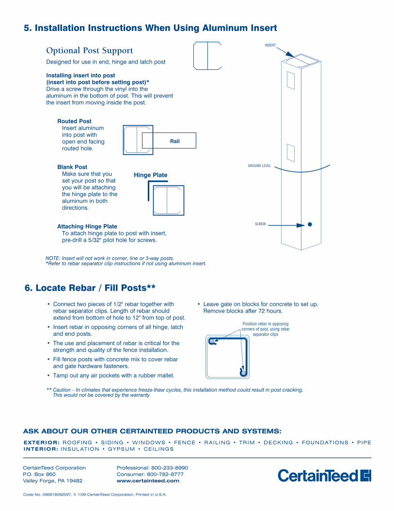
• Connect two pieces of 1/2" rebar together with rebar separator clips. Length of rebar should extend from bottom of hole to 12" from top of post.
• Insert rebar in opposing corners of all hinge, latch and end posts.
• The use and placement of rebar is critical for the strength and quality of the fence installation.
• Fill fence posts with concrete mix to cover rebar and gate hardware fasteners.
• Tamp out any air pockets with a rubber mallet.
• Leave gate on blocks for concrete to set up. Remove blocks after 72 hours.
6. Locate Rebar / Fill Posts**
Position rebar in opposingcorners of post, using rebar
separator clips
** Caution – In climates that experience freeze-thaw cycles, this installation method could result in post cracking. This would not be covered by the warranty.
CertainTeed Corporation P.O. Box 860Valley Forge, PA 19482
Professional: 800-233-8990 Consumer: 800-782-8777 www.certainteed.com
ASK ABOUT OUR OTHER CERTAINTEED PRODUCTS AND SYSTEMS:
Code No. 096818092597, © 1/09 CertainTeed Corporation, Printed in U.S.A.
ExTERIOR: Roofing • S iding • WindoWS • fence • Rail ing • TRiM • decking • foundaTionS • P iPeINTERIOR: inSulaTion • gYPSuM • ceil ingS
5. Installation Instructions When Using Aluminum Insert
Optional Post SupportDesigned for use in end, hinge and latch post
Installing insert into post (insert into post before setting post)*Drive a screw through the vinyl into the aluminum in the bottom of post. This will prevent the insert from moving inside the post.
Routed Post Insert aluminum into post with open end facing routed hole.
Blank Post Make sure that you set your post so that you will be attaching the hinge plate to the aluminum in both directions.
Attaching Hinge Plate To attach hinge plate to post with insert, pre-drill a 5/32" pilot hole for screws.
INSERT
GROUND LEVEL
SCREW
Rail
NOTE: Insert will not work in corner, line or 3-way posts.* Refer to rebar separator clip instructions if not using aluminum insert.
INSERT
GROUND LEVEL
SCREW
Hinge Plate
INSERT
GROUND LEVEL
SCREW
INSERT
GROUND LEVEL
SCREW