gate 2010 ece descriptive solution
TRANSCRIPT

8/8/2019 Gate 2010 ECE Descriptive Solution
http://slidepdf.com/reader/full/gate-2010-ece-descriptive-solution 1/24
Manifold Institute of Technical Education,
Opp: Ramdas Theatre,M.G Road Thrisur.Ph. 0487 3243929,09846894455
Manifoldkerala.org Dedicate your logic for your dreams gatetutor.com
Descriptive solution for GATE 2010 ECE
1.C
For a matrix to be skew symmetric,
= −Let A = [ ] be a given skew symmetric matrix. Then by definition = − for all
values of i and j. In particular, = − for a skew symmetric matrix. Therefore we have + = 0 => = 0 for every i.
Thus every element on the main diagonal of a skew symmetric matrix is always zero.
Eg: Let A =0 − 0 −
− 0[ −λI] =
− − − −− −= -λ( + ) − ( − ) + ( − − )= − − − + − − = − − ( + + )
І A – λI І= 0 + ( + + ) = 0
(
+ +
+
) = 0
λ = 0, = −( + + ) λ =± j√ + + Hence the eigen values of a skew symmetric matrix are either zero or purely imaginary.
2.C
The given signal is even since (−) = (). So the Trigonometric Fourier series contains
only d.c. term and cosine terms. Here d.c. term is the average value.
d.c. term =
= −
Hence the d.c term is negative. So fourier series contains a negative d.c. term and cosine
terms only.
3.D
Given :(() − () = 0
This can be written as − = 0

8/8/2019 Gate 2010 ECE Descriptive Solution
http://slidepdf.com/reader/full/gate-2010-ece-descriptive-solution 2/24
Manifold Institute of Technical Education,
Opp: Ramdas Theatre,M.G Road Thrisur.Ph. 0487 3243929,09846894455
Manifoldkerala.org Dedicate your logic for your dreams gatetutor.com
= ± Therefore Solution is
n(x)= + Given Boundary Condition:
1. n(0) = K
K = + 2. n(∞) = 0
= 0
K =
∴ () = 4.CI 1 A 0.5Ω B I 2
1 • • 2
V1 0.5Ω 0.5Ω V2
1’ 2’
Applying KCL to node A
1 = 10.5 + 1−20.5= 1 10.5 + 10.5 − 20.5
= 1(2 + 2) − 221=41−22 ----------(a)
Applying KCL to node B
2 = 20.5 + 2 − 10.5 = − 10.5 1 + 2 10.5 + 10.5

8/8/2019 Gate 2010 ECE Descriptive Solution
http://slidepdf.com/reader/full/gate-2010-ece-descriptive-solution 3/24
Manifold Institute of Technical Education,
Opp: Ramdas Theatre,M.G Road Thrisur.Ph. 0487 3243929,09846894455
Manifoldkerala.org Dedicate your logic for your dreams gatetutor.com
= −21+2(2 + 2)2= −21+4 ---------(b)
Network function is given by
1 = 11 1 + 12 ----------(1)
2 = 21 1 + 22 2 ------------(2)
Comparing (a) with (1) & (b) with (2)
Y11 = 4 S
Y12 = Y21 =-2 S
Y22 = 4 S
Thus the short circuit admittance matrix is given as
4 −2−2 45.DThe graph shows the relation between the impedance and frequency of a parallel RLC circuit
f
For f < , > f> , >
At f= , = =
Parallel RLC

8/8/2019 Gate 2010 ECE Descriptive Solution
http://slidepdf.com/reader/full/gate-2010-ece-descriptive-solution 4/24
Manifold Institute of Technical Education,
Opp: Ramdas Theatre,M.G Road Thrisur.
Ph. 0487 3243929,09846894455
Band width, B = 1/RC
So as R increases, B decreases. Also B is independent of L.
At resonance input impedance is a real quantity and attains its maximum value (Refer thegraph shown)
So option D is not correct for parallel RLC.
6. B = 1350/(−)7. B
For oxide thickness less than 100nm (thin oxide layer) we use dry oxidation.
8.B.
Collector current of Q1 = (10-0.7)/9.3 = 1mA,Since the base connections are same and
emitter area of Q2 is double Q2 carries collector current of 2 mA.
9.A.
Without Emitter capacitor input impedance is multiplied by β+1, and due to the negative
feedback voltage gain decreases.
10.A
Circuit can be redrawn as ,
11.D
The Boolean expression for the given logic gates can be written as follows
= + = = = +
= ⊕ = +

8/8/2019 Gate 2010 ECE Descriptive Solution
http://slidepdf.com/reader/full/gate-2010-ece-descriptive-solution 5/24
Manifold Institute of Technical Education,
Opp: Ramdas Theatre,M.G Road Thrisur.Ph. 0487 3243929,09846894455
Manifoldkerala.org Dedicate your logic for your dreams gatetutor.com
= ⊙ = + 1 = ⊕ = + = ⊙ 2 = + 3 = ⊙ = + = ⊕ 4 = Comparing all the 8 equations we can see that
P = 4, Q = 2, R = 3, S = 1
12.D
For an n-input XNOR gate,
a) If n is ODD, then for even number of 1’s present at the input, the output is 1
b) If n is ODD, then for odd number of 1’s present at the input, the output is 0
For 2 input XOR gate, output is 1 if the two inputs are different
For 2 input XNOR gate, output is 1 if the two inputs are same
The condition mentioned in the question is satisfied only by the input combination, A=0, B =0& C =1
13. B
The input to the device is fed in the address range A15 – A0. This is given to a 3 to 8 decoder
whose output is at Y5. For Y5 o be active, the input to ABC should be 101.
For 2 to be active, the output of NAND gate should be low. So the required address range
is
A15 A14 A13 A12 A11 A10 A9 A8 A7 A6 A5 A4 A3 A2 A1 A0
Min: 0 0 1 0 1 1 0 1 0 0 0 0 0 0 0 0
Max: 0 0 1 0 1 1 0 1 1 1 1 1 1 1 1 1
So the range is: 2D00 – 2DFF
14.A
Given, X (z) = 5z² + 4z⁻¹ +3 .Also given that ROC is the entire Z- plane with the exception at z=0
& z=∞
Generally we know,
() = []
Comparing the given X (z) with the general expression we get
x[n] at n = -2 is 5 δ[n]
x[n] at n = 1 is 4 δ[n]
x[n] at n=0 is 3 δ[n]
Combining these results we get the x[n] as follows:
x[n] = 5 δ[n+2] + 3 δ[n] + 4 δ[n-1]

8/8/2019 Gate 2010 ECE Descriptive Solution
http://slidepdf.com/reader/full/gate-2010-ece-descriptive-solution 6/24
Manifold Institute of Technical Education,
Opp: Ramdas Theatre,M.G Road Thrisur.Ph. 0487 3243929,09846894455
Manifoldkerala.org Dedicate your logic for your dreams gatetutor.com
15.C
The overall impulse response of a cascaded system is the convolution of individual impulse
response. In the question it is given two discrete time systems are cascaded. And it is also
given that the impulse response of first system is h1 [n] = δ[n-1] and that of second system is
h2[n] = δ[n-2].
Thus the net impulse response is h[n] = h1 [n] * h2[n]
h[n] = δ [n-1] * δ [n-2]
= δ [n-3]
16. D.
Each butterfly involves one complex multiplication and two complex additions. The same 2N
storage locations are used throughout the computation of N – point DFT, in place
computations.
17.B
Feed back signal is zero here, so its an open loop system with transfer function 1/(s+1).
18.B
() () = + () =cos(2−/3) ℎ () = (2−/2)( ) =
+ ∠( ) = (∞) −
= 90 −
( ) = ( )( )Here ω=2
ІH(jω)І =2/√ (4+p²)
∠H(jω) = 90 - tan⁻¹(2/p)
So, () = 2/ 4 + cos (2−()

8/8/2019 Gate 2010 ECE Descriptive Solution
http://slidepdf.com/reader/full/gate-2010-ece-descriptive-solution 7/24
Manifold Institute of Technical Education,
Opp: Ramdas Theatre,M.G Road Thrisur.Ph. 0487 3243929,09846894455
Manifoldkerala.org Dedicate your logic for your dreams gatetutor.com
From given y(t),
= 12 = 4 + 4 = 4 +
3 = 4 = 43 = 2√ 3
19. A
General Transfer function is =
Here the initial section of the plot shows a Zero of the Transfer function, since the magnitude
of the plot is increasing and at indicates a pole since the magnitude remains constant at 40
dB.
From fig: = 0.1 (has a Zero at this point).
= 10 (has a Pole at this point).
So = = . = 10 = = =0.1
Transfer function is =.
20. C
General form of AM signal is
() = [ 1 + ()] cos2 () = cos2 = So () = cos2 + () cos2 For signal without over modulation, value of µ ≤ 1. Here = 2.
∴ µ = 2

8/8/2019 Gate 2010 ECE Descriptive Solution
http://slidepdf.com/reader/full/gate-2010-ece-descriptive-solution 8/24

8/8/2019 Gate 2010 ECE Descriptive Solution
http://slidepdf.com/reader/full/gate-2010-ece-descriptive-solution 9/24
Manifold Institute of Technical Education,
Opp: Ramdas Theatre,M.G Road Thrisur.Ph. 0487 3243929,09846894455
Manifoldkerala.org Dedicate your logic for your dreams gatetutor.com
0 T
Where h(t) = s ( - t – T)
25. C
Given data: - = 1E = 1 V/m;
∈= 4Power = [ ]
= ∩ where H=
=
= ∈∈ √ ∈ = 120π
∴ = 120√ ∈ = 1202 =60.Power =
× =
26. A
Given = Taking log on both sides.
y ln e = ln
y =
() = ()() = = −
= −
= 0
− = 0 1 − l n = 0 ln x = 1

8/8/2019 Gate 2010 ECE Descriptive Solution
http://slidepdf.com/reader/full/gate-2010-ece-descriptive-solution 10/24
Manifold Institute of Technical Education,
Opp: Ramdas Theatre,M.G Road Thrisur.Ph. 0487 3243929,09846894455
Manifoldkerala.org Dedicate your logic for your dreams gatetutor.com
x =
= − 2
− 1
+ 2
= − + 2 At x=e
= − 3 + 2 l n = 1= − +
= − 1 = −0.049Since
is –ve function has a maximum value at x = e.
27. D
Sample space = (HHHH), (HHHT), (HHTH), (HTHH), (THHH), (HHTT), (HTTH), (HTHT),
(TTHH), (THTH), (THHT), (HTTT), (THTT), (TTHT), (TTHT), (TTTH), (TTTT)
Required condition: Number of times head shows up is more than number of times tails
Shows up .
So required space = (HHHH),(HHHT),(HHTH), (HTHH), (THHH)
So the probability of given event =
.28. C y
3 D E
C
1 A B
0√
√ x
= + From A to B

8/8/2019 Gate 2010 ECE Descriptive Solution
http://slidepdf.com/reader/full/gate-2010-ece-descriptive-solution 11/24
Manifold Institute of Technical Education,
Opp: Ramdas Theatre,M.G Road Thrisur.Ph. 0487 3243929,09846894455
Manifoldkerala.org Dedicate your logic for your dreams gatetutor.com
∮ . = ∫ + (√ √ )
= ∫ ℎ = 1
√ √
=∫ √ √
= [ ] √
√
= − = = ...................[1]
From B to E
∮ . = ∫ + ( )= ∫ here = √ =
∫ =
[] = 2= ..........................[2]
From E to D
∮ . = ∫ + (
√ √ )= ∫ ℎ = 3√ √
=3 ∫ √ √
= 3 [ ] √
√
= − = − = − ..............................[3]
From D to A
∮ . = ∫ + ( )= ∫ here = √ =
∫

8/8/2019 Gate 2010 ECE Descriptive Solution
http://slidepdf.com/reader/full/gate-2010-ece-descriptive-solution 12/24
Manifold Institute of Technical Education,
Opp: Ramdas Theatre,M.G Road Thrisur.Ph. 0487 3243929,09846894455
Manifoldkerala.org Dedicate your logic for your dreams gatetutor.com
= [] =
− 2 = ..........................[4]
Overall integral is
∮ . = [1] +[2] +[3] +[4]
= + − − = − + = − 1 + 2 = 1
29. C
() = ()()Residue at z = a is given by lim→( − ) ()Residues are at = 0 , = 1 , = 2Residue at z=0 is
lim→()
()()= lim→ ()()()= =
Residue at z=1 is lim→ ()()()()= lim→ ()()=
() = − = 1Residue at z = 2 is lim→ ()()()()
= lim→ ()()=
() = − 30. A
Given = +
(, ) = +
(0) = 0 , ℎ = 0 . 1 = (0) + ℎ (, ) = 0 + 0.1(0 + 0) = 0
= + ℎ (, ) = 0 + 0.1(0.15 + 0)
= 0.015

8/8/2019 Gate 2010 ECE Descriptive Solution
http://slidepdf.com/reader/full/gate-2010-ece-descriptive-solution 13/24
Manifold Institute of Technical Education,
Opp: Ramdas Theatre,M.G Road Thrisur.
Ph. 0487 3243929,09846894455
Y(0.3) = 0.015
31. D
() =
()Given lim→ () = 1
Lim→ () = lim→ ()
lim→
() =lim→
3 + 1 + 4 + ( − 3) = 1
1 − 3 = 1
1 = − 3
= 432. A
Initially switch is open (t<0), inductor attains a steady state value. The circuit can be redrawn
as
The resistors are of equal value, so the current divides equally.
() = 1.52 = 0.75
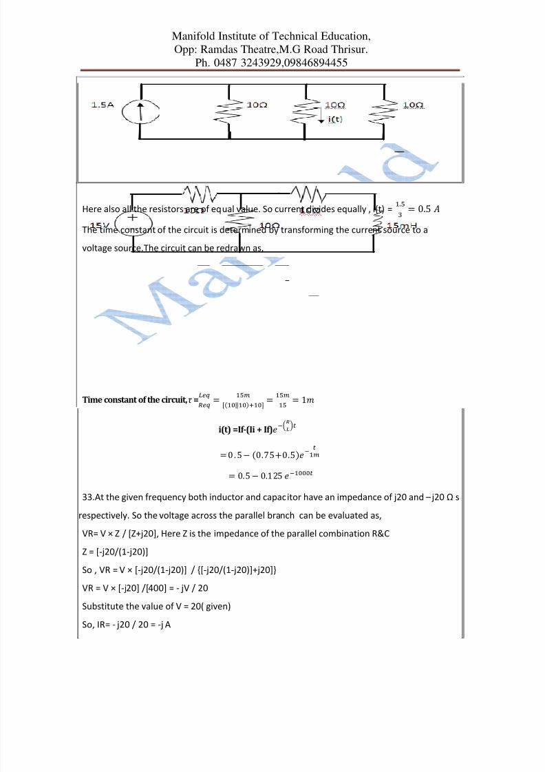
At t =0 switch is closed. At steady state the circuit appears as parallel combination of three
10Ω resistors along with the current source.
8/8/2019 Gate 2010 ECE Descriptive Solution
http://slidepdf.com/reader/full/gate-2010-ece-descriptive-solution 14/24
Manifold Institute of Technical Education,
Opp: Ramdas Theatre,M.G Road Thrisur.
Ph. 0487 3243929,09846894455
Here also all the resistors are of equal value. So current divides equally , i(t) =. = 0.5
The time constant of the circuit is determined by transforming the current source to a
voltage source.The circuit can be redrawn as,
Time constant of the circuit,τ
=
=
[(‖)] =
= 1i(t) =If-(Ii + If)
= 0 . 5 − (0.75+0.5)
= 0.5 − 0.125
33.At the given frequency both inductor and capacitor have an impedance of j20 and – j20 Ω s
respectively. So the voltage across the parallel branch can be evaluated as,
VR= V × Z / [Z+j20], Here Z is the impedance of the parallel combination R&C
Z = [-j20/(1-j20)]
So , VR = V × [-j20/(1-j20)] / [-j20/(1-j20)]+j20]
VR = V × [-j20] /[400] = - jV / 20
Substitute the value of V = 20( given)
So, IR= - j20 / 20 = -j A

8/8/2019 Gate 2010 ECE Descriptive Solution
http://slidepdf.com/reader/full/gate-2010-ece-descriptive-solution 15/24
Manifold Institute of Technical Education,
Opp: Ramdas Theatre,M.G Road Thrisur.
Ph. 0487 3243929,09846894455
34.A
Let I1, I2&I3 are the mesh currents, writing mesh equations we have,
10 = 2 I1 +2 I2 ....(1)
I1 – I2 = 1 .. (2)
From (1) & (2) we get I1 = 3 A & I2 = 2 A
So its clear that I3 = 0 A ( see the fig below), Hence the power supplied is 0 watts.
35. B
For the required condition , the transistor should have High doping at the emitter side(NE >>
NB) and very less base area compared to collector(NB > NC)
36.C
The doping concentration in the second p-n junction is higher than that of first.As doping
increases, The field intensity in the semiconductor also increases, leads to zener
37. D
CLOCK DA DB DC QA QB QC OUTPUT
1 0 0 0 0 0 0 0
2 1 0 0 1 0 0 1
3 1 1 0 1 1 0 1
4 0 1 1 0 1 1 05 1 0 1 1 0 1 1
6 0 1 0 0 1 0 0
7 0 0 1 0 0 1 0
8 0 0 0 0 0 0 0
38.B

8/8/2019 Gate 2010 ECE Descriptive Solution
http://slidepdf.com/reader/full/gate-2010-ece-descriptive-solution 16/24
Manifold Institute of Technical Education,
Opp: Ramdas Theatre,M.G Road Thrisur.
Ph. 0487 3243929,09846894455
After thevenizing the circuit,
Here RTH= 4/5 R and VTH = (4 + 4/5 VI)
For VI ranging from -5 to ∞ the out pot of the opamp is at negative value, diode D2 ON &D1
OFF, so the out put voltage is zero (no current flows through R).
For VI ranging from −∞ to -5 the out pot of the opamp is at positive value, diode D1ON &D2
OFF, so the out put voltage is given by,
-R/RTH × [VTH] = - R/RTH × [4+4/5 VI] = [5/4] × [4+4/5 VI] = -[ 5 + VI ]
39. D
Output function = + + + Here = = So we can replace above equation by
= + + +
A B C D F
0 0 0 0 0
0 0 0 1 0
0 0 1 0 1

8/8/2019 Gate 2010 ECE Descriptive Solution
http://slidepdf.com/reader/full/gate-2010-ece-descriptive-solution 17/24
Manifold Institute of Technical Education,
Opp: Ramdas Theatre,M.G Road Thrisur.Ph. 0487 3243929,09846894455
Manifoldkerala.org Dedicate your logic for your dreams gatetutor.com
0 0 1 1 1
0 1 0 0 0
0 1 0 1 1
0 1 1 0 0
0 1 1 1 1
1 0 0 0 1
1 0 0 1 1
A B C D F
1 0 1 0 0
1 0 1 1 0
1 1 0 0 1
1 1 0 1 0
1 1 1 0 0
1 1 1 1 0
F(A,B,C,D) = ∑ ( 2,3,5,7,8,9,12)40. C
3000 MVI A, 45H ; A = 45H
3002 MOV A, B ; B = 45H
3003 STC ; Set carry i.e. cy = 1
3004 CMC ; Complement carry i.e. cy =0
3005 RAR ; Rotate right through carry
; → → → → → → → →
3006 XRA B ; XOR A with BBefore execution of RAR content of A is
cy
0 1 0 0 0 1 0 1 0
After execution of RAR instruction content of A is

8/8/2019 Gate 2010 ECE Descriptive Solution
http://slidepdf.com/reader/full/gate-2010-ece-descriptive-solution 18/24
Manifold Institute of Technical Education,
Opp: Ramdas Theatre,M.G Road Thrisur.Ph. 0487 3243929,09846894455
Manifoldkerala.org Dedicate your logic for your dreams gatetutor.com
cy
0 0 1 0 0 0 1 0 1
Now its Hexadecimal equivalent is 22H.
After XOR operation of 22H with 45H
0 1 0 0 0 1 0 1
0 0 1 0 0 0 1 0
0 XOR 0 =0, 1 XOR 1 =0, 0 XOR 1 = 1 XOR 0 = 0.
The result is
0 1 1 0 0 1 1 1
The content of A is 67H.
41. B.
() + 4 () + 3 () = 2 () + 4 () ………[1]Given () = () … … … … … . [2]Taking Laplace transform of [2]
() = Taking Laplace transform of [1]
() + 4() + 3 () = 2() + 4() (Here Zero initial conditions)
( + 4 + 3) () = (2 + 4)()() = ()()( )
=()( ) () (Substituting X(s)) ( + 4 + 3 = ( + 3)( +1))
Applying partial fraction method
()() = + Taking L.C.M, we get
2 = A (s +1) + B( s + 3) ...............[a]
Put s = -1, in [a]
2 = 2B => B = 1.

8/8/2019 Gate 2010 ECE Descriptive Solution
http://slidepdf.com/reader/full/gate-2010-ece-descriptive-solution 19/24
Manifold Institute of Technical Education,
Opp: Ramdas Theatre,M.G Road Thrisur.Ph. 0487 3243929,09846894455
Manifoldkerala.org Dedicate your logic for your dreams gatetutor.com
Put s = -3 in [a]
2 = -2 A => A = -1
∴ () = − () + Taking Inverse Laplace transform
() = − () + () = ( − )()42. C
() =
Multiplying by 8 on both numerator and denominator above equation becomes
H(z) =
(
− 6
+ 8 = (
− 2)(
− 4))= ( )( )Taking partial fraction
( )( ) = ( ) + ( )Taking L.C.M
16−6 = ( − 4) + ( − 2)Put = 416 – (6*4) = B (4 – 2)
B = − = −4Put = 216 – (6*2) = A (2 -4)
A = = −2
∴ () = − ( ) − ( )=
−
−
=
+
So R.O.C of first fraction is R.O.C of second fraction is
|
|< 1 |
|< 1

8/8/2019 Gate 2010 ECE Descriptive Solution
http://slidepdf.com/reader/full/gate-2010-ece-descriptive-solution 20/24
Manifold Institute of Technical Education,
Opp: Ramdas Theatre,M.G Road Thrisur.Ph. 0487 3243929,09846894455
Manifoldkerala.org Dedicate your logic for your dreams gatetutor.com
|| < 1
|| < 1
<||
<||
|z| > |z| > So the R.O.C of the entire function lies in the region || > . The H(z) is stable for this region
only which implies is wrong. R.O.C doesn’t exists in the region < || < .
Hence option C is correct.
43. C
() = = cos(500+700) − cos(500−700)
cos (A +B) – cos(A –B) = cosAcosB - sinAsinB –cosAcosB + sinAsinB
= 2 sinAsinB
() = [cos1200−cos200]Nyquist sampling frequency is chosen for the highest frequency component present in the
signal. Here highest frequency component is due to that of 1200π. Its frequency is obtained as
shown below. General form is cosωt.
= 2 . Here ω = 1200π.∴2=1200 f = 600 Hz.
So Nyquist sampling frequency = 2f = 2*600 = 1200 Hz.
44.D.
Only option ‘D’ will change the type, and a type 1(or more) system will gives zero steady
state error for a unit step input.
45. D

8/8/2019 Gate 2010 ECE Descriptive Solution
http://slidepdf.com/reader/full/gate-2010-ece-descriptive-solution 21/24
Manifold Institute of Technical Education,
Opp: Ramdas Theatre,M.G Road Thrisur.Ph. 0487 3243929,09846894455
Manifoldkerala.org Dedicate your logic for your dreams gatetutor.com
X(t) + Y(t)
+
( ) = |( )| ( ) Y(t) =
[( () + ( − 0 . 5 ∗ 1 0)] ( ) = ( ) + .∗ ( ) . () =( )
. ( − ) = ()( ) ( ) = ( 1 + .∗)( ) = ( ) ( ) = 1 + .∗
= ( 1 + (0.5∗10) + sin(0.5∗10))| ( )| = √((1+0.5∗10) + (sin0.5∗10))= 1+0.5∗10 + 2 0.5 ∗ 10 + 0.5∗10
= √ 2 + 2 0.5 ∗ 10.
|( )| = 2[ 2 + 2 cos 0.5 ∗ 10 ∗2]= 2[2 + 2 c o s ∗ 1 0]At f = 1KHz
|( )| =210[ 2 + 2c os ] = 210[ 2 − 2] = 0.( ) = |( )| ( ) = 0.
So for f = 1 KHz, 3KHz, 5KHz.........etc the value of ( ) = 0.
So ( ) = 0 for f = (2n + 1) where = 1 and n is any integer
48. B.
Given
= 1 , = 2 5 9 , =93Input Resistance seen by source = + //.= 1000 + = 1000 + 258 = 1258Ω
49. B
Given = 250Ω, = 1KΩ, =4.7μF
Delay = 0.5ms
+

8/8/2019 Gate 2010 ECE Descriptive Solution
http://slidepdf.com/reader/full/gate-2010-ece-descriptive-solution 22/24
Manifold Institute of Technical Education,
Opp: Ramdas Theatre,M.G Road Thrisur.Ph. 0487 3243929,09846894455
Manifoldkerala.org Dedicate your logic for your dreams gatetutor.com
The lower cut off frequency due to , =()
=1/[2(250+1000)4.7]= 1/0.369 Hz
= 27.1 Hz
50. B 2 1/s 1/s 1 0.5
U(s) • • • • • •Y(s)
-1
-1
From figure it is clear that
= 2U(s) – = – Y(s) = 0.5( +)
= 0.5( – +)
Y(s) = 0.5General state variable representation is
= + i.e., = +
where = =
General state variable representation of output is
= [ℎ ]i.e., Y = CX
From the signal flow graph we get
= −1 1−1 0 + 02 = −1 1−1 0 + 02

8/8/2019 Gate 2010 ECE Descriptive Solution
http://slidepdf.com/reader/full/gate-2010-ece-descriptive-solution 23/24
Manifold Institute of Technical Education,
Opp: Ramdas Theatre,M.G Road Thrisur.Ph. 0487 3243929,09846894455
Manifoldkerala.org Dedicate your logic for your dreams gatetutor.com
= [0 0.5] = [0 0.5]
On comparing with the general state variable representation it is clear that
= −1 1−1 0 = 02 & = [0 0.5]
51. C
The general form of transfer function in state variable representation is given by
()() = [ − ] [ − ] = + 1 −11
| − | = ( + 1) + 1= + + 1
[ − ] = 1 + + 1 1−1 + 1[ − ] = [0 0.5] 1 + + 1 1−1 + 1
= [−0.5 0.5( + 1) ] [ − ] = 1 + + 1 [−0.5 0.5( + 1)] 02= 1 + + 1 [2 × 0 . 5 × ( + 1)]
= + 1 + + 1Hence the transfer function is
62.It is a base 8 arithmetic.
So,
2+1 = 3
7+3 = 10, 10-8 = 2 and a carry of 1
6+7+1(carry) = 14, 14 – 8 = 6 and a carry of 1

8/8/2019 Gate 2010 ECE Descriptive Solution
http://slidepdf.com/reader/full/gate-2010-ece-descriptive-solution 24/24
Manifold Institute of Technical Education,
Opp: Ramdas Theatre,M.G Road Thrisur.Ph. 0487 3243929,09846894455
So it comes as, 1623