gas turbine
TRANSCRIPT
11
CHAPTER 2
LITERATURE REVIEW
2.1 Introduction
A gas turbine combustor having a fuel injection nozzle for diffusion combustion
disposed in a central portion of the combustor and an annular premixed nozzle disposed
in an outer peripheral portion of the fuel injection nozzle for injecting a mixed gas of
fuel and air. The annular premixed nozzle includes an annular premixing chamber and a
plurality of premixed fuel nozzles for injecting fuel into the annular premixing chamber.
The annular premix nozzle is divided by a partition (108) to form a plurality of
premixing chambers each adjacent to the fuel injection nozzle for diffusion combustion.
Each of the premixing chambers includes at least one of the premixed fuel nozzles. A
mechanism is provided for supplying fuel to a predetermined number of the premixing
chambers in a low load operation of the gas turbine and for supplying fuel to all of the
premixing chambers in a high load operation
12
2.2 Combustion Fundamentals
Combustion perhaps describe most simply as an exothermic reaction of a fuel
and an oxidant. In gas turbine application the fuel may be gaseous or liquid, but the
oxidant is always air. Combustion occurs in many forms, not all of which are
accompanied by flame or luminescence. The following regimes of combustion can be
distinguished. (A.B Wassel, 1977)
2.3 Pre-Flame Combustion
This is a slow process that normally requires from 1 to 100 second reaching 80%
completion. The reaction occurs throughout an extended volume at temperatures ranging
from 600 to 800 K. The products of combustion contain high concentrations of
oxygenated organic species; hence, only part of the latent heat of combustion is
released.
2.4 Deflagration
This is a fast process that requires less than 1 ms for 80% completion. It is
characterized by the presence of flame that propagates through the unburned mixture. A
flame may be defined as a rapid chemical change occurring in a very this layer,
involving steep gradients of temperature and species concentrations, and accompanied
by luminescence. From a macroscopic viewpoint the flame front can be viewed as an
interface between the burned gases and the unburned mixture. Compared with the
unburned mixture, the burned gases are much higher in volume and temperature, and
much lower density. Deflagration waves normally propagate at velocities below 1m/s.
All the flame processes occurring in gas turbine combustors fall within this category.
13
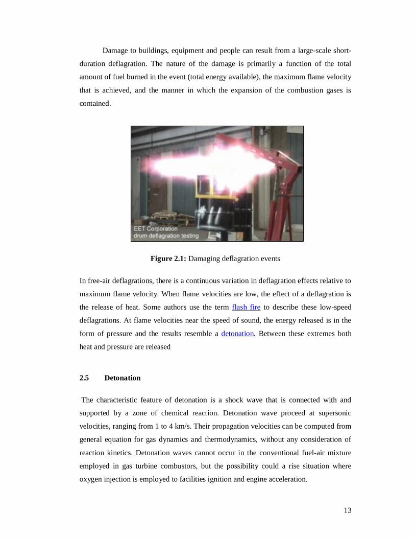
Damage to buildings, equipment and people can result from a large-scale short-
duration deflagration. The nature of the damage is primarily a function of the total
amount of fuel burned in the event (total energy available), the maximum flame velocity
that is achieved, and the manner in which the expansion of the combustion gases is
contained.
Figure 2.1: Damaging deflagration events
In free-air deflagrations, there is a continuous variation in deflagration effects relative to
maximum flame velocity. When flame velocities are low, the effect of a deflagration is
the release of heat. Some authors use the term flash fire to describe these low-speed
deflagrations. At flame velocities near the speed of sound, the energy released is in the
form of pressure and the results resemble a detonation. Between these extremes both
heat and pressure are released
2.5 Detonation
The characteristic feature of detonation is a shock wave that is connected with and
supported by a zone of chemical reaction. Detonation wave proceed at supersonic
velocities, ranging from 1 to 4 km/s. Their propagation velocities can be computed from
general equation for gas dynamics and thermodynamics, without any consideration of
reaction kinetics. Detonation waves cannot occur in the conventional fuel-air mixture
employed in gas turbine combustors, but the possibility could a rise situation where
oxygen injection is employed to facilities ignition and engine acceleration.
14
2.6 Gas Turbine Combustor
Gas turbine engines are widely used in aircraft, marine, power generation and
industrial application due to largely tremendous advantages in term of range, speed, fuel
economy, passenger comfort, compactness and high power output. Conventional gas
turbine combustion chamber essentially consists of three main sections. These are
primary, intermediate and dilution zones. The most vital section for the combustion
chamber designer is the primary zone since combustion of fuel is initiated in this section
(Al-Kabie, H.S., 1989). The achievement of complete combustion in the primary zone is
the aim of the present work which reduces the need for other sections of the combustors
fulfilling the requirement of small size and light weight of gas turbines.
2.7 Theory of Operation
Gas turbines are described thermodynamically by the Brayton cycle, in which air
is compressed isentropically, combustion occurs at constant pressure, and expansion
over the turbine occurs isentropically back to the starting pressure.
In practice, friction, and turbulence cause:
a) non-isentropic compression: for a given overall pressure ratio, the compressor
delivery temperature is higher than ideal.
b) non-isentropic expansion: although the turbine temperature drop necessary to
drive the compressor is unaffected, the associated pressure ratio is greater, which
decreases the expansion available to provide useful work.
c) pressure losses in the air intake, combustor and exhaust: reduces the
expansion available to provide useful work.
15
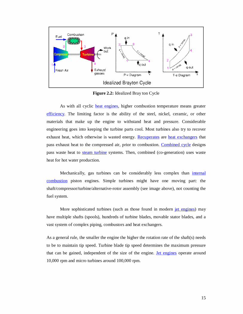
Figure 2.2: Idealized Bray ton Cycle
As with all cyclic heat engines, higher combustion temperature means greater
efficiency. The limiting factor is the ability of the steel, nickel, ceramic, or other
materials that make up the engine to withstand heat and pressure. Considerable
engineering goes into keeping the turbine parts cool. Most turbines also try to recover
exhaust heat, which otherwise is wasted energy. Recuperates are heat exchangers that
pass exhaust heat to the compressed air, prior to combustion. Combined cycle designs
pass waste heat to steam turbine systems. Then, combined (co-generation) uses waste
heat for hot water production.
Mechanically, gas turbines can be considerably less complex than internal
combustion piston engines. Simple turbines might have one moving part: the
shaft/compressor/turbine/alternative-rotor assembly (see image above), not counting the
fuel system.
More sophisticated turbines (such as those found in modern jet engines) may
have multiple shafts (spools), hundreds of turbine blades, movable stator blades, and a
vast system of complex piping, combustors and heat exchangers.
As a general rule, the smaller the engine the higher the rotation rate of the shaft(s) needs
to be to maintain tip speed. Turbine blade tip speed determines the maximum pressure
that can be gained, independent of the size of the engine. Jet engines operate around
10,000 rpm and micro turbines around 100,000 rpm.
16
Thrust bearings and journal bearings are a critical part of design. Traditionally, they
have been hydrodynamic oil bearings, or oil-cooled ball bearings. This is giving way to
foil bearings, which have been successfully used in micro turbines and auxiliary power
units.
2.8 Operation of a Gas Turbine Combustor
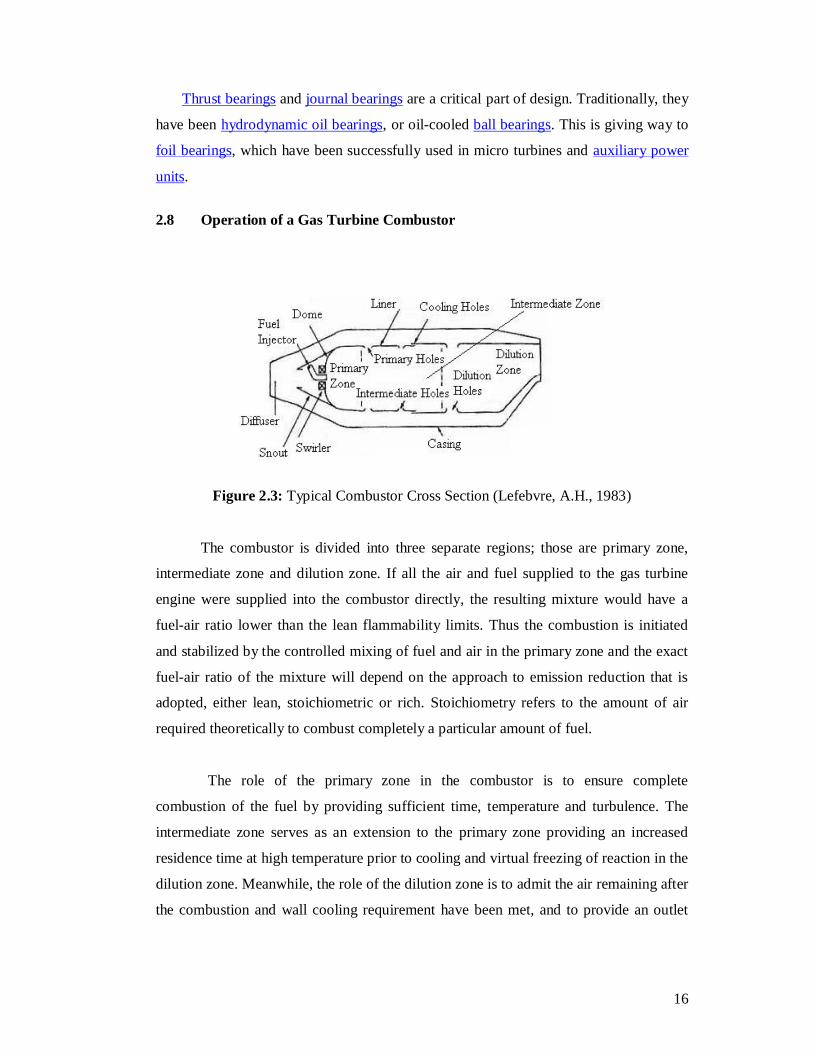
Figure 2.3: Typical Combustor Cross Section (Lefebvre, A.H., 1983)
The combustor is divided into three separate regions; those are primary zone,
intermediate zone and dilution zone. If all the air and fuel supplied to the gas turbine
engine were supplied into the combustor directly, the resulting mixture would have a
fuel-air ratio lower than the lean flammability limits. Thus the combustion is initiated
and stabilized by the controlled mixing of fuel and air in the primary zone and the exact
fuel-air ratio of the mixture will depend on the approach to emission reduction that is
adopted, either lean, stoichiometric or rich. Stoichiometry refers to the amount of air
required theoretically to combust completely a particular amount of fuel.
The role of the primary zone in the combustor is to ensure complete
combustion of the fuel by providing sufficient time, temperature and turbulence. The
intermediate zone serves as an extension to the primary zone providing an increased
residence time at high temperature prior to cooling and virtual freezing of reaction in the
dilution zone. Meanwhile, the role of the dilution zone is to admit the air remaining after
the combustion and wall cooling requirement have been met, and to provide an outlet
17
stream with a mean temperature and a temperature distribution that are acceptable to the
turbine.
2.8.1 Combustor Arrangement There are three common combustor arrangement; tubular, annular and tub
annular type combustors. Tubular combustor is also known as can-type combustor.
2.8.1.1 Tubular Combustor
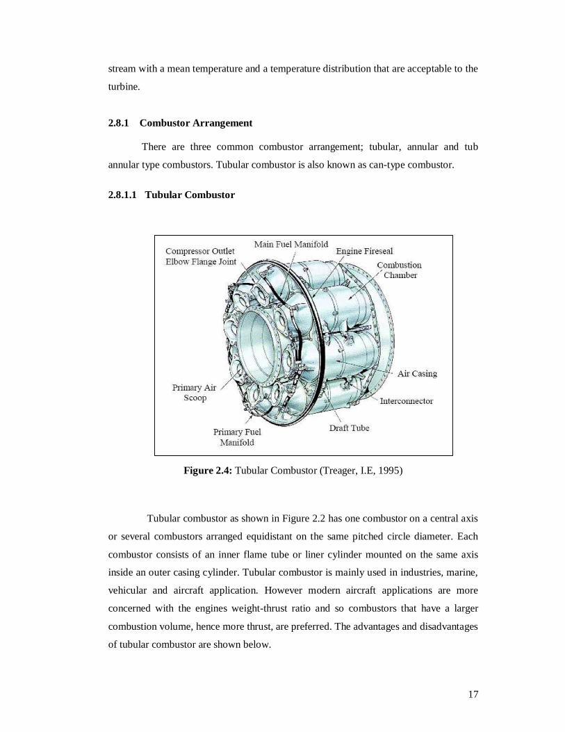
Figure 2.4: Tubular Combustor (Treager, I.E, 1995)
Tubular combustor as shown in Figure 2.2 has one combustor on a central axis
or several combustors arranged equidistant on the same pitched circle diameter. Each
combustor consists of an inner flame tube or liner cylinder mounted on the same axis
inside an outer casing cylinder. Tubular combustor is mainly used in industries, marine,
vehicular and aircraft application. However modern aircraft applications are more
concerned with the engines weight-thrust ratio and so combustors that have a larger
combustion volume, hence more thrust, are preferred. The advantages and disadvantages
of tubular combustor are shown below.
18
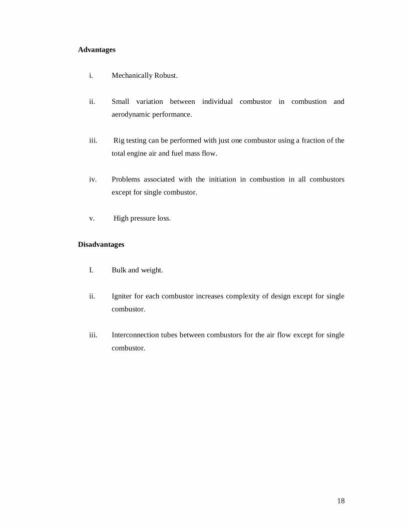
Advantages
i. Mechanically Robust.
ii. Small variation between individual combustor in combustion and
aerodynamic performance.
iii. Rig testing can be performed with just one combustor using a fraction of the
total engine air and fuel mass flow.
iv. Problems associated with the initiation in combustion in all combustors
except for single combustor.
v. High pressure loss.
Disadvantages
I. Bulk and weight.
ii. Igniter for each combustor increases complexity of design except for single
combustor.
iii. Interconnection tubes between combustors for the air flow except for single
combustor.
19
2.8.1.2 Annular Combustor
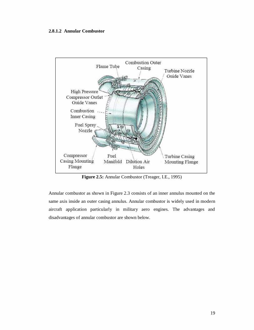
Figure 2.5: Annular Combustor (Treager, I.E., 1995)
Annular combustor as shown in Figure 2.3 consists of an inner annulus mounted on the
same axis inside an outer casing annulus. Annular combustor is widely used in modern
aircraft application particularly in military aero engines. The advantages and
disadvantages of annular combustor are shown below.
20
Advantages
i. Minimum length and weight.
ii. Minimum pressure loss.
iii. Minimal problems with light around.
Disadvantages
i. Buckling problems on outer liner leading to disruption of cooling air flow
and variation in outlet gas temperature creating possible thermal stresses in
the turbine blades.
ii. Rig testing requires use of total engine air and fuel mass flow.
iii. Even distribution of fuel and air is difficult to achieve around the annular.
21
2.8.1.3 Tuboannular Combustor
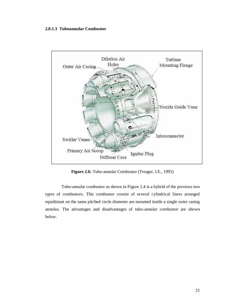
Figure 2.6: Tubo-annular Combustor (Treager, I.E., 1995)
Tubo-annular combustor as shown in Figure 2.4 is a hybrid of the previous two
types of combustors. This combustor consist of several cylindrical liners arranged
equidistant on the same pitched circle diameter are mounted inside a single outer casing
annulus. The advantages and disadvantages of tubo-annular combustor are shown
below.
22
Advantages
i. Mechanically robust.
ii. Low pressure loss.
iii. Shorter and lighter than tubular combustor.
iv. Rig testing requires use of just one combustor, using fraction of total engine
air and fuel flow.
Disadvantages
i. Suffers from the problem of light around.
ii. Less compact than annular combustor.
iii. Even distribution of air is difficult to achieve around the annulus.
iii. Igniter for each combustor increases the complexity of design.
23
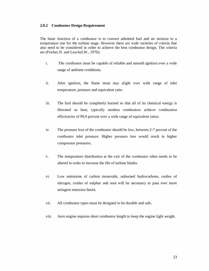
2.8.2 Combustor Design Requirement
The basic function of a combustor is to convert admitted fuel and air mixture to a temperature rise for the turbine stage. However there are wide varieties of criteria that also need to be considered in order to achieve the best combustor design. The criteria are (Fricker,N. and Leuckel,W., 1976):
i. The combustor must be capable of reliable and smooth ignition over a wide
range of ambient conditions.
ii. After ignition, the flame must stay alight over wide range of inlet
temperature, pressure and equivalent ratio.
iii. The fuel should be completely burned so that all of its chemical energy is
liberated as heat; typically modern combustors achieve combustion
efficiencies of 99.9 percent over a wide range of equivalent ratios.
iv. The pressure loss of the combustor should be low, between 2-7 percent of the
combustor inlet pressure. Higher pressure loss would result in higher
compressor pressures.
v. The temperature distribution at the exit of the combustor often needs to be
altered in order to increase the life of turbine blades.
vi. Low emissions of carbon monoxide, unburned hydrocarbons, oxides of
nitrogen, oxides of sulphur and soot will be necessary to pass ever more
stringent emission limits.
vii. All combustor types must be designed to be durable and safe.
viii. Aero engine requires short combustor length to keep the engine light weight.

24
2.9 Air Swirler
The main problem in the combustion system is to stabilize the flame in various
situations. This situation is totally difficult to archive mainly in the aircraft usage. It
cause by the variation of pressure in the combustion area. These problems will effect the
uncompleted combustion that create an emission that will impure the environment that
create air pollution such as black smoke and nitrogen dioxide.
In term of stabilizing the combustion flame, the common solution is to consider
the shape of air flow in main area. To built the turn back flow shape, a gadget known as
air swirler is use to create this kind of air flow shape. Basically, the injector is
surrounded by the air swirler. The air swirler will support at the air flow and the result
of whirling combustion that create vortecs. The low pressure area in the middle of the
vortecs will influence the circulation as shown in figure 2.5. There is various type of air
swirler is use for this purpose. Most of the combustor uses the air swirler to stabilize the
flame including the gas turbine.
Figure 2.7: Circulation created by air swirler (Mellor, 1990)
25
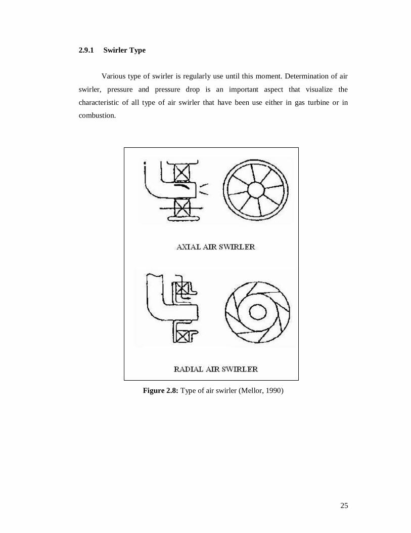
2.9.1 Swirler Type
Various type of swirler is regularly use until this moment. Determination of air
swirler, pressure and pressure drop is an important aspect that visualize the
characteristic of all type of air swirler that have been use either in gas turbine or in
combustion.
Figure 2.8: Type of air swirler (Mellor, 1990)
26
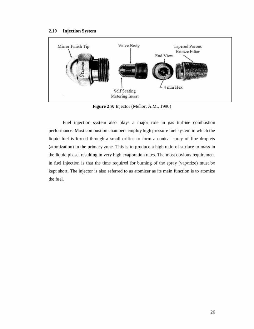
2.10 Injection System
Figure 2.9: Injector (Mellor, A.M., 1990)
Fuel injection system also plays a major role in gas turbine combustion
performance. Most combustion chambers employ high pressure fuel system in which the
liquid fuel is forced through a small orifice to form a conical spray of fine droplets
(atomization) in the primary zone. This is to produce a high ratio of surface to mass in
the liquid phase, resulting in very high evaporation rates. The most obvious requirement
in fuel injection is that the time required for burning of the spray (vaporize) must be
kept short. The injector is also referred to as atomizer as its main function is to atomize
the fuel.
27
2.10.1 Injectors Requirement Ideal fuel injectors would posses all the following characteristics (Lefebvre, A.H., 1983) and (Bent, R.D. and Mckinlay, J.L., 1985):
i. Good atomization over the entire range of fuel flows. ii. Rapid response to changes in throttle settings. iii. Freedom from flow instabilities. iv. Low susceptibility blockage by contamination and carbon deposition on the
nozzle. v. Low susceptibility to gum formation by heat soakage. vi. Capability for scaling, to provide design flexibility. vii. Low cost, lightweight, ease of manufacture and ease of removal for
servicing. viii. Low susceptibility to damage during manufacture and installation. ix. Freedom from vaporization icing, thus making it unnecessary to use
carburetor heat except under the most severe atmospheric conditions. x. More uniform delivery of the fuel-air mixture. xi. Improved control of the fuel-air ratio. xii. Reduction of maintenance problems. xiii. Instant acceleration of the engine after idling, with no tendency to stall. xiv. Increase engine efficiency. xv. An easy ignitable mixture. xvi. A ratio of maximum to minimum fuel flow that exceeds the ratio of
maximum to minimum combustor airflow. xvii. Controlled dispersion of the fuel throughout the primary combustion zone. xviii. An exit gas temperature distribution that is insensitive to variations in fuel
flow rate.

28
2.10.2 Atomization Process
In gas turbine combustion chambers, atomization is normally accomplished by
spreading the fuel into a thin sheet to induce instability and promote disintegration of
the sheet into drops. Thin sheets could be obtained by discharging the fuel through
orifice with specially shaped approach passage by forcing it through narrow slots, by
spreading it over a metal surface or by feeding it to the centre of a rotating disk. The
function of the atomizer is to attenuate the fuel into a fine jet or thin sheet from which
ligaments and ultimately drops will be produced and distribute the resulting drops
throughout the combustion zone in a controlled pattern and direction.
2.10.2.1 Jet Break Up
Several modes of jet disintegration have been identified, but in all cases the final
mechanism involves the break up of unstable threads of liquid into rows of drops
conforming to the classical mechanism postulated by Rayleigh (Lefebvre, A.H., 1983).
According to Rayleigh’s theory, liquid becomes unstable and breaks into drops when the
amplitude of a small disturbance, symmetrical about the axis of the jet, grows to one
half the diameter of the undisturbed liquid jet. This occurs when o /dλ = 4.5, where λ is
the wavelength of the disturbance and is the initial jet diameter. For this value of 4.5, the
average drop diameter of break up is 1.89, which is almost double of the diameter of
initial jet diameter. In Rayleigh’s theory, liquid viscosity is not considered. This theory
later extended by Weber to include the effect of liquid viscosity effect on the break up
(Lefebvre, A.H., 1983). According to Weber, the ratio0dodo/dλ of required to produce
maximum instability for viscous jets is given by:
When 1 µ = 0, the value of /odλ= 4.44, which is almost the same as the value of
Rayleigh’s prediction. However, when a liquid with viscosity of 0.86 kg/ms s
experimented, the ratio of /odλ for maximum instability ranged form 30 to 40. This
clearly differs from Rayleigh’s prediction.
29
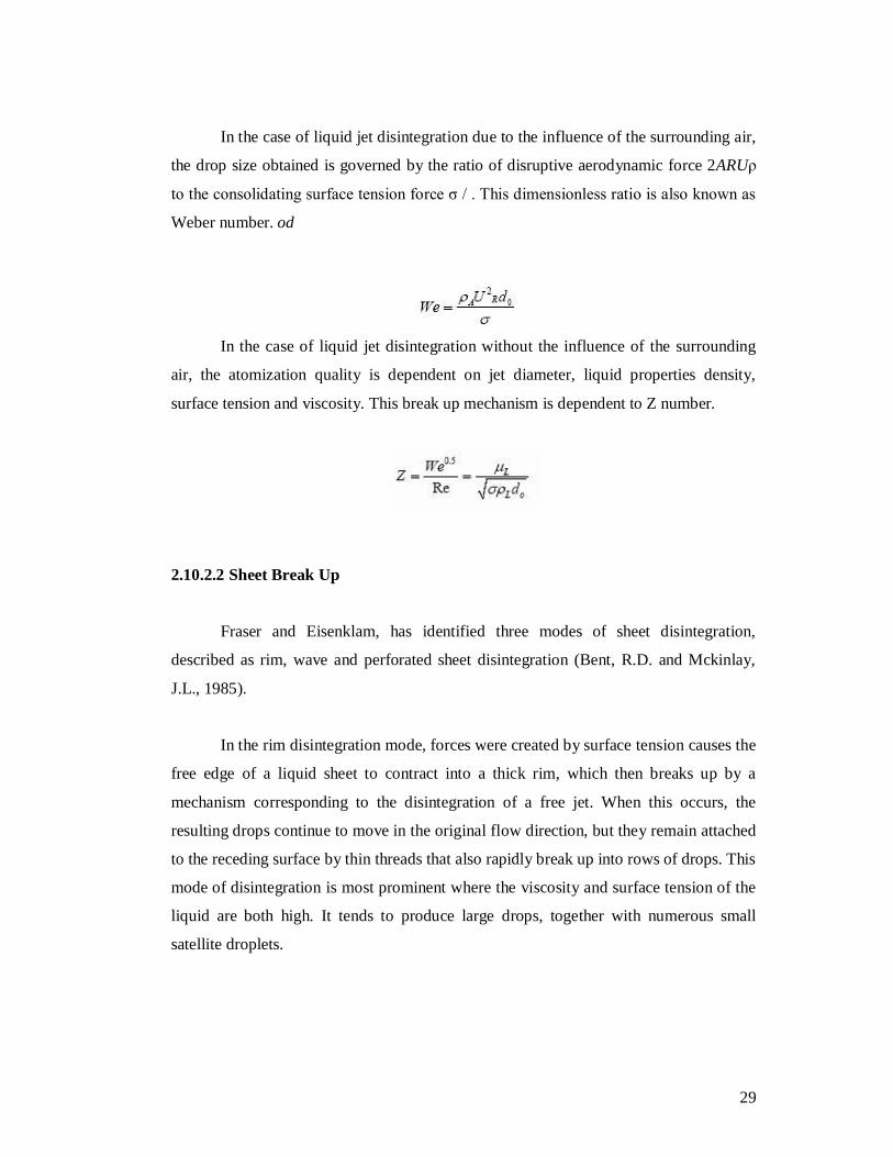
In the case of liquid jet disintegration due to the influence of the surrounding air,
the drop size obtained is governed by the ratio of disruptive aerodynamic force 2ARUρ
to the consolidating surface tension force σ / . This dimensionless ratio is also known as
Weber number. od
In the case of liquid jet disintegration without the influence of the surrounding
air, the atomization quality is dependent on jet diameter, liquid properties density,
surface tension and viscosity. This break up mechanism is dependent to Z number.
2.10.2.2 Sheet Break Up
Fraser and Eisenklam, has identified three modes of sheet disintegration,
described as rim, wave and perforated sheet disintegration (Bent, R.D. and Mckinlay,
J.L., 1985).
In the rim disintegration mode, forces were created by surface tension causes the
free edge of a liquid sheet to contract into a thick rim, which then breaks up by a
mechanism corresponding to the disintegration of a free jet. When this occurs, the
resulting drops continue to move in the original flow direction, but they remain attached
to the receding surface by thin threads that also rapidly break up into rows of drops. This
mode of disintegration is most prominent where the viscosity and surface tension of the
liquid are both high. It tends to produce large drops, together with numerous small
satellite droplets.
30
In perforated sheet disintegration, holes appear in the sheet at a certain distance
from the orifice. The holes are delineated by rims formed from the liquid that was
initially included inside. These holes grow rapidly in size until the rims of adjacent holes
coalesce to produce ligaments of irregular shape that finally break up into drops of
varying size.
Atomizers that discharge the fuel in the form of sheet are usually capable of
exhibiting all three modes of sheet disintegration. Sometimes two different modes occur
simultaneously, and their relative importance can greatly influence both the mean drop
size and the drop size distribution.
2.10.3 Spray Characteristics
Combustion performance is also dependence on spray characteristic such as
mean drop size, drop size distribution, spray pattern, cone angle, dispersion and
penetration. Mean drop size and drop size distribution are important in designing the
atomizer meanwhile spray pattern, cone angle, dispersion and penetration are governed
partly by atomizer design and partly by the aerodynamics influence to which the spray is
subjected after atomization is completed.
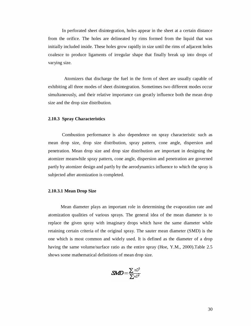
2.10.3.1 Mean Drop Size
Mean diameter plays an important role in determining the evaporation rate and
atomization qualities of various sprays. The general idea of the mean diameter is to
replace the given spray with imaginary drops which have the same diameter while
retaining certain criteria of the original spray. The sauter mean diameter (SMD) is the
one which is most common and widely used. It is defined as the diameter of a drop
having the same volume/surface ratio as the entire spray (Hoe, Y.M., 2000).Table 2.5
shows some mathematical definitions of mean drop size.
31
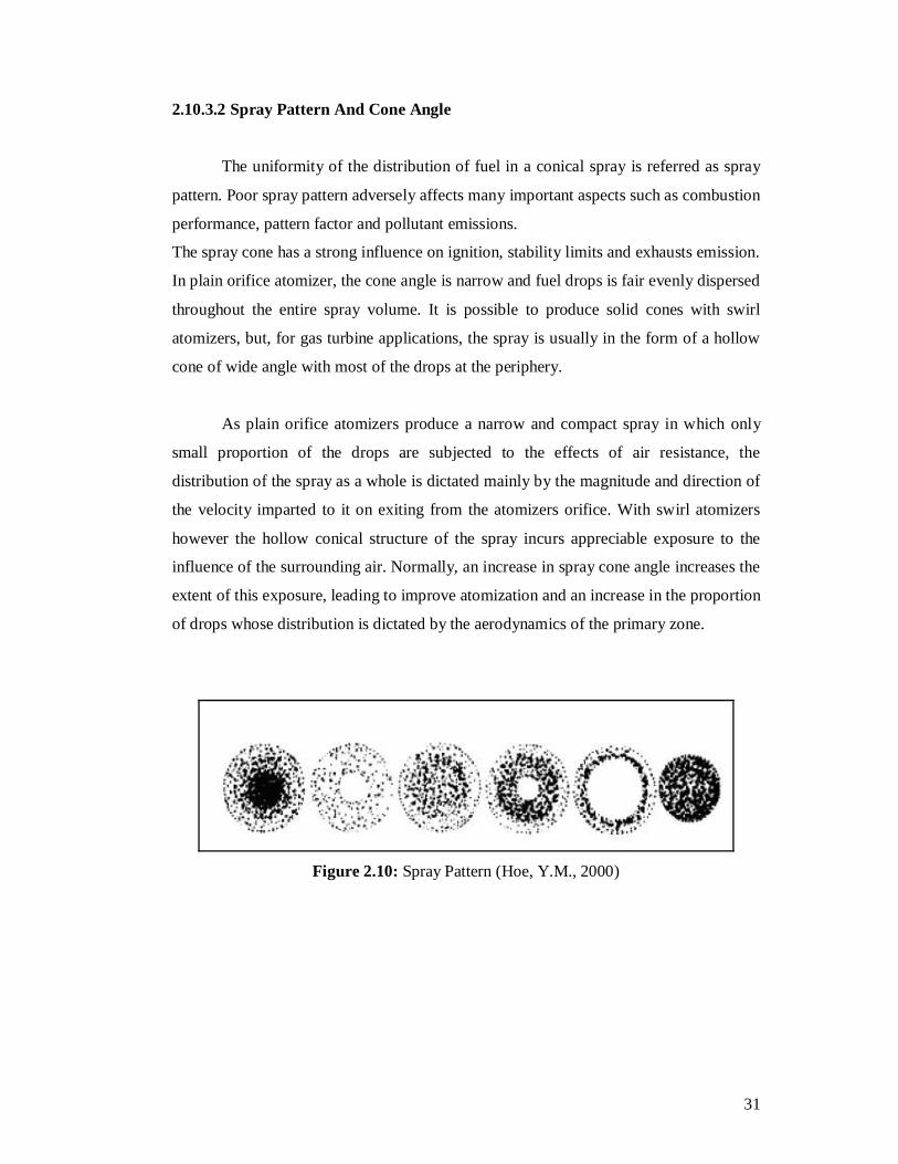
2.10.3.2 Spray Pattern And Cone Angle
The uniformity of the distribution of fuel in a conical spray is referred as spray
pattern. Poor spray pattern adversely affects many important aspects such as combustion
performance, pattern factor and pollutant emissions.
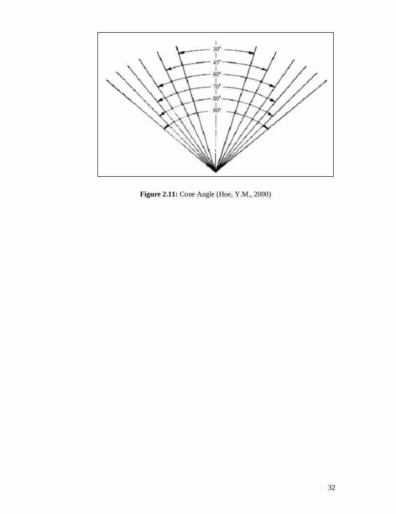
The spray cone has a strong influence on ignition, stability limits and exhausts emission.
In plain orifice atomizer, the cone angle is narrow and fuel drops is fair evenly dispersed
throughout the entire spray volume. It is possible to produce solid cones with swirl
atomizers, but, for gas turbine applications, the spray is usually in the form of a hollow
cone of wide angle with most of the drops at the periphery.
As plain orifice atomizers produce a narrow and compact spray in which only
small proportion of the drops are subjected to the effects of air resistance, the
distribution of the spray as a whole is dictated mainly by the magnitude and direction of
the velocity imparted to it on exiting from the atomizers orifice. With swirl atomizers
however the hollow conical structure of the spray incurs appreciable exposure to the
influence of the surrounding air. Normally, an increase in spray cone angle increases the
extent of this exposure, leading to improve atomization and an increase in the proportion
of drops whose distribution is dictated by the aerodynamics of the primary zone.
Figure 2.10: Spray Pattern (Hoe, Y.M., 2000)
33
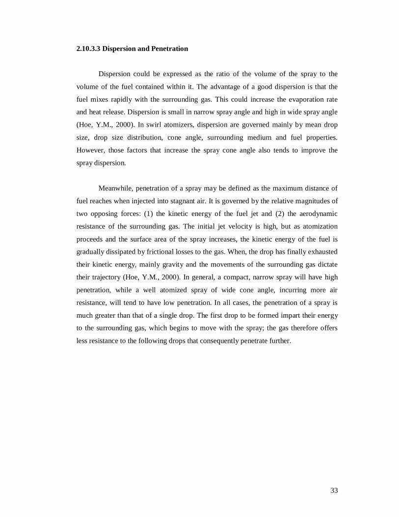
2.10.3.3 Dispersion and Penetration
Dispersion could be expressed as the ratio of the volume of the spray to the
volume of the fuel contained within it. The advantage of a good dispersion is that the
fuel mixes rapidly with the surrounding gas. This could increase the evaporation rate
and heat release. Dispersion is small in narrow spray angle and high in wide spray angle
(Hoe, Y.M., 2000). In swirl atomizers, dispersion are governed mainly by mean drop
size, drop size distribution, cone angle, surrounding medium and fuel properties.
However, those factors that increase the spray cone angle also tends to improve the
spray dispersion.
Meanwhile, penetration of a spray may be defined as the maximum distance of
fuel reaches when injected into stagnant air. It is governed by the relative magnitudes of
two opposing forces: (1) the kinetic energy of the fuel jet and (2) the aerodynamic
resistance of the surrounding gas. The initial jet velocity is high, but as atomization
proceeds and the surface area of the spray increases, the kinetic energy of the fuel is
gradually dissipated by frictional losses to the gas. When, the drop has finally exhausted
their kinetic energy, mainly gravity and the movements of the surrounding gas dictate
their trajectory (Hoe, Y.M., 2000). In general, a compact, narrow spray will have high
penetration, while a well atomized spray of wide cone angle, incurring more air
resistance, will tend to have low penetration. In all cases, the penetration of a spray is
much greater than that of a single drop. The first drop to be formed impart their energy
to the surrounding gas, which begins to move with the spray; the gas therefore offers
less resistance to the following drops that consequently penetrate further.
34
2.10.4 Types of Atomizers
There are several atomizers that are used for combustion applications. Several
types of atomizers are briefly described in this section. Relative merits of these
atomizers were simplified and accessible.
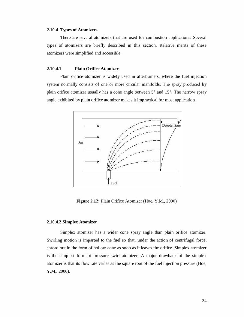
2.10.4.1 Plain Orifice Atomizer
Plain orifice atomizer is widely used in afterburners, where the fuel injection
system normally consists of one or more circular manifolds. The spray produced by
plain orifice atomizer usually has a cone angle between 5° and 15°. The narrow spray
angle exhibited by plain orifice atomizer makes it impractical for most application.
Figure 2.12: Plain Orifice Atomizer (Hoe, Y.M., 2000)
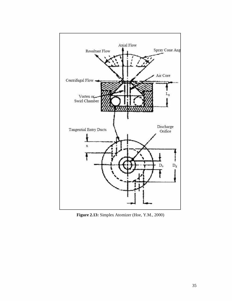
2.10.4.2 Simplex Atomizer Simplex atomizer has a wider cone spray angle than plain orifice atomizer.
Swirling motion is imparted to the fuel so that, under the action of centrifugal force,
spread out in the form of hollow cone as soon as it leaves the orifice. Simplex atomizer
is the simplest form of pressure swirl atomizer. A major drawback of the simplex
atomizer is that its flow rate varies as the square root of the fuel injection pressure (Hoe,
Y.M., 2000).
36
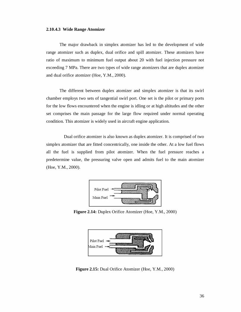
2.10.4.3 Wide Range Atomizer
The major drawback in simplex atomizer has led to the development of wide
range atomizer such as duplex, dual orifice and spill atomizer. These atomizers have
ratio of maximum to minimum fuel output about 20 with fuel injection pressure not
exceeding 7 MPa. There are two types of wide range atomizers that are duplex atomizer
and dual orifice atomizer (Hoe, Y.M., 2000).
The different between duplex atomizer and simplex atomizer is that its swirl
chamber employs two sets of tangential swirl port. One set is the pilot or primary ports
for the low flows encountered when the engine is idling or at high altitudes and the other
set comprises the main passage for the large flow required under normal operating
condition. This atomizer is widely used in aircraft engine application.
Dual orifice atomizer is also known as duplex atomizer. It is comprised of two
simplex atomizer that are fitted concentrically, one inside the other. At a low fuel flows
all the fuel is supplied from pilot atomizer. When the fuel pressure reaches a
predetermine value, the pressuring valve open and admits fuel to the main atomizer
(Hoe, Y.M., 2000).
Figure 2.14: Duplex Orifice Atomizer (Hoe, Y.M., 2000)
Figure 2.15: Dual Orifice Atomizer (Hoe, Y.M., 2000)

37
2.10.4.4 Spill Return Atomizer Basically, spill return atomizer is almost similar to simplex atomizer. Spill return
atomizer differs from simplex atomizer such that the rear wall of the swirl chamber
instead of being solid, it contains an annular passage which fuel can be spilled away
from the atomizer. Fuel is supplied to the swirl chamber at high pressure and high flow
rate (Hoe, Y.M., 2000)
Figure 2.16: Spill Return Atomizer (Hoe, Y.M., 2000)
2.10.4.5 Fan Spray Atomizer
Fan spray atomizer is usually obtained by cutting slots into plane or cylindrical
surfaces and arranging for the fuel into each slot from two opposite directions. In the
single hole fan spray atomizer, there is only one single orifice; this orifice forces the
liquid into two opposite streams within itself, so that a fan spray issues from the orifice
and spreads out in the shape of a sector of a circle of about 75° angle. An air shroud is
usually fitted around the atomizer tip, using the pressure differential across the linear
wall (Hoe, Y.M., 2000).
Figure 2.17: Fan Spray Atomizer (Hoe, Y.M., 2000)
38
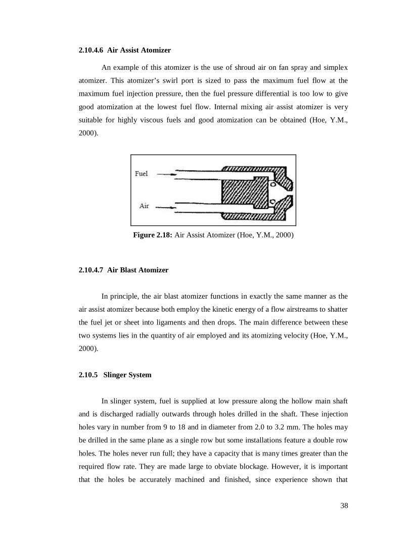
2.10.4.6 Air Assist Atomizer
An example of this atomizer is the use of shroud air on fan spray and simplex
atomizer. This atomizer’s swirl port is sized to pass the maximum fuel flow at the
maximum fuel injection pressure, then the fuel pressure differential is too low to give
good atomization at the lowest fuel flow. Internal mixing air assist atomizer is very
suitable for highly viscous fuels and good atomization can be obtained (Hoe, Y.M.,
2000).
Figure 2.18: Air Assist Atomizer (Hoe, Y.M., 2000)
2.10.4.7 Air Blast Atomizer
In principle, the air blast atomizer functions in exactly the same manner as the
air assist atomizer because both employ the kinetic energy of a flow airstreams to shatter
the fuel jet or sheet into ligaments and then drops. The main difference between these
two systems lies in the quantity of air employed and its atomizing velocity (Hoe, Y.M.,
2000).
2.10.5 Slinger System
In slinger system, fuel is supplied at low pressure along the hollow main shaft
and is discharged radially outwards through holes drilled in the shaft. These injection
holes vary in number from 9 to 18 and in diameter from 2.0 to 3.2 mm. The holes may
be drilled in the same plane as a single row but some installations feature a double row
holes. The holes never run full; they have a capacity that is many times greater than the
required flow rate. They are made large to obviate blockage. However, it is important
that the holes be accurately machined and finished, since experience shown that
39
uniformity of flow among injection holes depends on their dimensional accuracy and
surface finish. If one injection holes supplies more fuel than others, a rotating hot spot
will be formed in the exhaust gases, with disastrous consequence for the particular
turbine blade on which the hot spot happens to impinge.
The advantage of the slinger system is that it is low in cost and simple. Only low
pressure fuel pump is needed and atomization quality depends on engine speed. The
influence of fuel viscosity is small, so the system has a potential multifuel capability.
One drawback of the slinger system is its slow response to changes in fuel flow. A more
serious problem is that of high altitude relighting performance. With the engine wind
milling, the rotational speed is quite low and consequently the atomization quality is
relatively poor. This system is suitable for small engines. The problems of wall cooling
could arise if the system were applied to engines with high pressure ratios (Hoe, Y.M.,
2000).
2.10.6 Flame Stabilizer
One of the main basic requirements of the combustor is to support combustion
over a wide range of operating conditions. This could be achieved by an appropriately
designed flame stabilizer. Flame stabilization could be achieved if a sheltered region is
provided to entrain and recirculates some of the hot combustion burnt gases with the
fresh incoming fuel and air mixture. There are several types of flame stabilizer such as
bluff bodies, opposed jets, jet mix and grid mix, axial swirler and radial swirler.
40
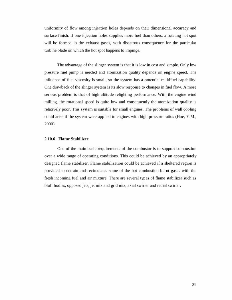
2.10.6.1 Bluff Body The bluff body flame stabilizer causes a flow recirculation by creating a low pressure zone in its near wake region.
Figure 2.19: Bluff Body Flame Stabilizers
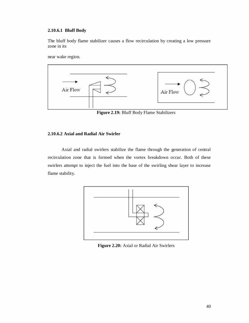
2.10.6.2 Axial and Radial Air Swirler
Axial and radial swirlers stabilize the flame through the generation of central
recirculation zone that is formed when the vortex breakdown occur. Both of these
swirlers attempt to inject the fuel into the base of the swirling shear layer to increase
flame stability.
Figure 2.20: Axial or Radial Air Swirlers
41
CHAPTER 3
SWIRLER DESIGN CONCEPT 3.1 Swirler Design
Swirling jets were used for stabilization and control of flame and to achieve high
intensity combustion. The common method of generating swirl is by using angled vanes
in the passages of air.
Most conventional combustors employ the axial flow type swirlers. The swirler
vanes were usually flat for ease of manufacture, but curved vane was sometimes used
for their better aerodynamics properties (Lefebvre, 1983). Ahmad, et al. (1986) found
problems in the achievement of adequate combustion efficiency and stability with lean
primary zones using large air flow axial swirler with central fuel injection (Kim, 1995).
Alkabie, et al. (1988) showed that these problems could be overcome by the use of
radial swirler followed by a dump expansion with their quite different near swirler
aerodynamic.
For large air flow, the axial swirler has disadvantages for accommodating more
air because the expansion from the swirler is reduced by the requirement to increase the
swirler diameter. Increasing the air flow would reduce the flow expansion to the
combustor diameter. The expansion ratio should be more than 1.5 to create a corner
recirculation zone. However, this problem not encountered with radial swirlers since the
radial swirler outlet can be maintained constant and the vane depth increased to
accommodate more air to achieve the pressure loss required. Alkabie (1989) found the
noticeable improvement in performance and NOx emission of the radial swirler over the
axial swirler due to the immediate contact of fuel with the turbulent swirled air as it
leaves the central fuel injector.So, in this research, the axial swirlers would be used.
42
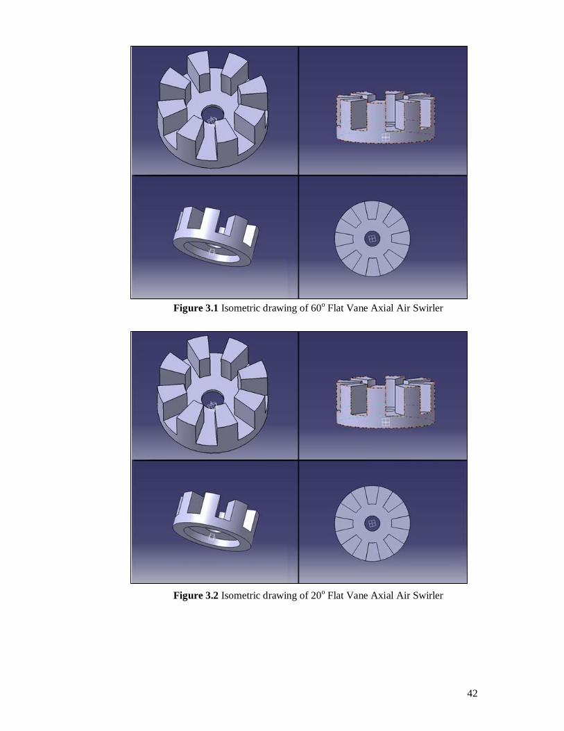
Figure 3.1 Isometric drawing of 60o Flat Vane Axial Air Swirler
Figure 3.2 Isometric drawing of 20o Flat Vane Axial Air Swirler
43
3.1.1 Swirler Aerodynamics
A basic requirement of all gas turbine is that the flame stay lighted over a wide
range of operating conditions. This is especially arduous for the aircraft combustor,
which has to cope with the adverse conditions of low pressure and temperature and
occasionally the ingestion of rain or ice. The primary-zone airflow pattern is of prime
importance to flame stability. Many different types of airflow pattern are employed, but
one feature common to all is the creation of a torroidal flow reversal that entrains and
recirculates a portion of the hot combustion product to mix with the incoming air and
fuel. These vortices are continually refreshed by air admitted through holes pierced in
the liner walls, supplemented in most cases by air flowing through swirlers and flare-
cooling slots, and sometimes by air employed in atomization.
One of the most effective ways of inducing flow recirculation in the primary
zone is to fit a swirler in the dome around the fuel injector. Vortex breakdown is a well-
known phenomenon in swirling flows; it causes recirculation in the core region when
the amount of rotation imparted to the flow is high. This type of recirculation provides
better mixing than is normally obtained by other means, such as bluff bodies, because
swirl components produce strong shear regions, high turbulence and rapid mixing rates.
These characteristics of swirling flows have long been recognized and have been used in
many practical combustion devices to control the stability an intensity of combustion
and the size and shape of the flame region
44
3.1.2 Rapid Mixing
There are number of ways of producing better mixing between air and fuel. One of
the ways is by creating rapid mixing combustion system. Rapid fuel and air mixing are
best produced by using swirlers.
To achieve rapid fuel and air mixing, turbulence must be generated to promote the
mixing. Turbulence energy is created from pressure energy dissipated downstream of
the stabilizer. In swirlers, increasing the blockage or pressure drop of the swirler can
generate turbulence. Swirler pressure drop could be done in number of ways:
i. Increasing the swirler vane angle.
ii. Decreasing the swirler outlet diameter (d/D) or increasing the swirler hub
diameter, both of which increase the swirler flow blockage.
iii. Increasing the number of vanes.
Besides the effect of rapid fuel and air mixing, all of these factors also increase the
size of the recirculation zone. An increase in the size of the recirculation zone together
with the turbulence generated in the shear layer region can increase fuel and air mixing
significantly.
45
3.1.3 Swirl Flow
Swirl flow is a main flow produced by air swirled in burner system. Such flow is
the combination of swirling motion and vortex breakdown. Swirling flow is widely used
to stabilize the flame in combustion chamber. Swirling flow induces a highly turbulent
recirculation zone that stabilizes the flame resulting in better mixing and combustion.
An advantage of swirling flow is the fact that a centrifugal force field, present in
swirling, tends to accelerate the mixing of two flows having different densities and thus
increase the reaction rate in the combustion process (Fricker, N. and Leuckel, W., 1976).
The primary function of this flow is to achieve a mixture that can sustain
continuous, and to maintain or stabilize combustion over a wide range of operating
conditions. Air is introduced tangentially into the combustion chamber and forced to
change its path, which contributes to the formation of swirling flow. The strength of the
flow is dependent on the swirler vane angle and the air pressure supplied.
Swirl is widely used in industrial application ranging from gas turbine
combustors to diesel engines. It is often dictates that the supported flame must be short
and intense in continuous combustion system such as gas turbine combustor in order to
achieve the maximum heat release quickly. Long flames are generally less well mixed,
this can be gauged by the apparent of yellow flame and contribute more to pollutant
formation as the residence time is higher. Additionally yellow flames, as there are more
rich regions, the temperature is less uniform across the flame and fluctuations in
temperature can have a profound increasing effect on the NOx emissions (Escott, N.H.,
1993).
46
3.1.4 Effect of Swirl
The introduction of swirl has been applied extensively in industrial furnace and
combustion chambers in order to improve flame stabilization (Wu, H. L. and Fricker,
N., 1976). Swirl also has been used as a mean of controlling flame shape and
combustion intensity in furnace flames. The effect of swirl is to decrease the velocity
gradient at the exit of burner thus causing a faster decay of the velocities in the flow
field with increase of swirl flow (Chervinskey, A. and Manheimertiment, Y., 1968).
One of the main effects of thef application of swirl into a flow is the central
reverse flow zone that is formed and a highly complex turbulent flow field creates the
reverse flow zone or recirculation zone, as shown in Figure 3.1, has traditionally been
regarded as a reservoir or store of heat and active chemical species. It cyclically
transports hot combustion products from downstream regions into the flame region. The
high temperature products, despite the dilution effect, serve as an energy source for
preheating and ignition assistance. Between the forward flow and the reverse flow zone
boundary is a region of steep velocity gradients and high intensity turbulence, which
promotes high entrainment rates and rapid mixing between the fuel and air.
As a result of the high entrainment and homogeneous mixing, swirl reduces both
flame lengths and flame attachment lengths and consequently shortens the combustion
chamber length necessary for complete combustion (Kim, M.N., 1995). Swirl also
promotes high combustion efficiency, easy ignition, reactant recirculation zone
residence time, pollutant optimization potential, widened stability and blow off limits.
47
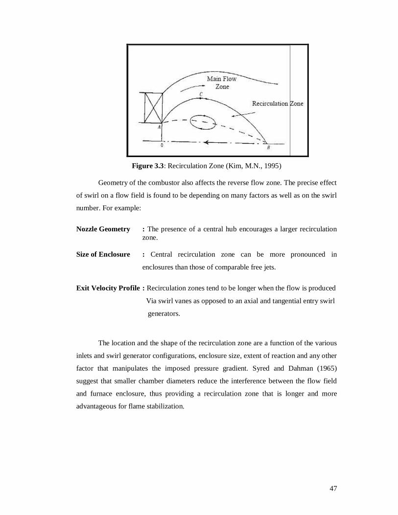
Figure 3.3: Recirculation Zone (Kim, M.N., 1995)
Geometry of the combustor also affects the reverse flow zone. The precise effect
of swirl on a flow field is found to be depending on many factors as well as on the swirl
number. For example:
Nozzle Geometry : The presence of a central hub encourages a larger recirculation
zone. Size of Enclosure : Central recirculation zone can be more pronounced in
enclosures than those of comparable free jets.
Exit Velocity Profile : Recirculation zones tend to be longer when the flow is produced
Via swirl vanes as opposed to an axial and tangential entry swirl
generators.
The location and the shape of the recirculation zone are a function of the various
inlets and swirl generator configurations, enclosure size, extent of reaction and any other
factor that manipulates the imposed pressure gradient. Syred and Dahman (1965)
suggest that smaller chamber diameters reduce the interference between the flow field
and furnace enclosure, thus providing a recirculation zone that is longer and more
advantageous for flame stabilization.
48
3.1.5 Swirl Stabilized Flame
The primary zone airflow pattern of gas turbine combustors is of major
importance of flame stability. Various types of airflow pattern are employed, but one
feature common to all is the creation of a torroidal reverse flow. This torroidal vortex
system plays an important role in flame stabilization since it entrains and recirculates a
portion of the hot combustion product to mix with the incoming air and fuel. One of the
most effective ways to induce recirculation flow in the primary zone is by fitting a
swirler around the fuel injector. This type of recirculation zone may provide better
mixing than that obtained by other means such as bluff body. This is because of the
strong shear regions, high turbulence and rapid mixing rates produced by the swirling
action. Besides that, the presence of a solid surface exposed to the high temperature is
reduced and the deposition of coke such as occur on bluff bodies in heterogeneous
combustion is also reduced.
Swirl increases the production of turbulence above that generated by non-
swirling flows because the presence of the tangential velocity component provides
additional velocity gradient. Swirling also increases the turbulence burning velocity to
ensure blow off does not occur. Besides that, recirculation vortex produced by swirl acts
as a heat source forcing combustion product to move upstream and mix with the
partially premixed reactant. This increases the amount of contact between fuel, air and
hot combustion products (Syred, N. and Beer, J.M., 1974). An additional factor that
explains why swirl has a stabilizing effect is that stagnation points are found at upstream
and / or downstream positions of central recirculation zone. This stagnation point would
act as a bluff body with the flame attaching in the sheltered downstream near wake
region.

49
3.1.6 Swirler Pressure Drop
Swirler pressure drop is equal to the different in pressure between the plenum chamber and the combustor. The swirler pressure drop was calculated as follows (Escott, N.H., 1993).
Pns and PnD are the static and dynamic pressure in the n region. Pa is the
atmospheric pressure. As the combustor is placed horizontally, it was assumed that Δ h
1≈ Δ h3 ≈ 0 and ρ1 = ρ3.Thus, the equations (3.2) and (3.3) can be combined to yield:
Values of pressure loss in a typical gas turbine combustor lie between 2 percent
to 7 percent at reference Mach number of 0.047 (Clements, T.R., 1976). The pressure
loss can be calculated by using the following equation:
50
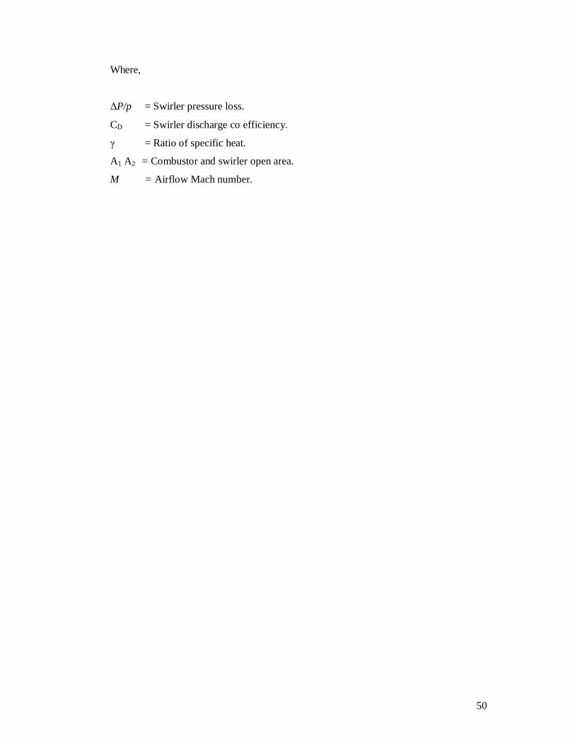
Where,
ΔP/p = Swirler pressure loss.
CD = Swirler discharge co efficiency.
γ = Ratio of specific heat.
A1 A2 = Combustor and swirler open area.
M = Airflow Mach number.
51
3.1.7 Swirl Number
The previous experimental studies have shown that the flame size, shape,
stability and combustion intensity are affected by the degree of swirl imposed on the
flow. This degree of swirl is denoted by the swirl number S, which is a non-dimensional
number characterizing the amount of rotation imposed to the flow. An advantage of
swirling flow combustion is the fact that a centrifugal force field, present in swirling or
vortex flow, tends to accelerate the mixing of two flows having different densities and
thus increase the reaction rate in the combustion process.
The common method of generating swirl is by using angled vanes in the
passages of air. The characteristic of the swirling flow depends on the swirler vane
angle. Basically there are two types of swirler design; axial swirler and radial swirler.
Most conventional combustor employs the axial flow type of swirler. The swirler vane
is usually flat for ease of manufacture, but curved vane is sometimes performed for their
better aerodynamic properties.
Alkabie, et al (1988) found problems in the achievement of adequate combustion
efficiency and stability with lean primary zones using large air flow axial swirler with
central fuel injection. Alkabie, et al (1988) showed that these problems could be
overcome by the use of radial swirler followed by dump expansion with their quite
different near swirler aerodynamic. Flat vane swirler is inefficient because they run
under stalled condition.
Swirl number represents the axial flux of swirl momentum divided by the axial
flux of axial momentum and is widely used for characterizing the intensity of swirl in
enclosed and fully separated flow. That is (Kim, M.N., 1995).
52
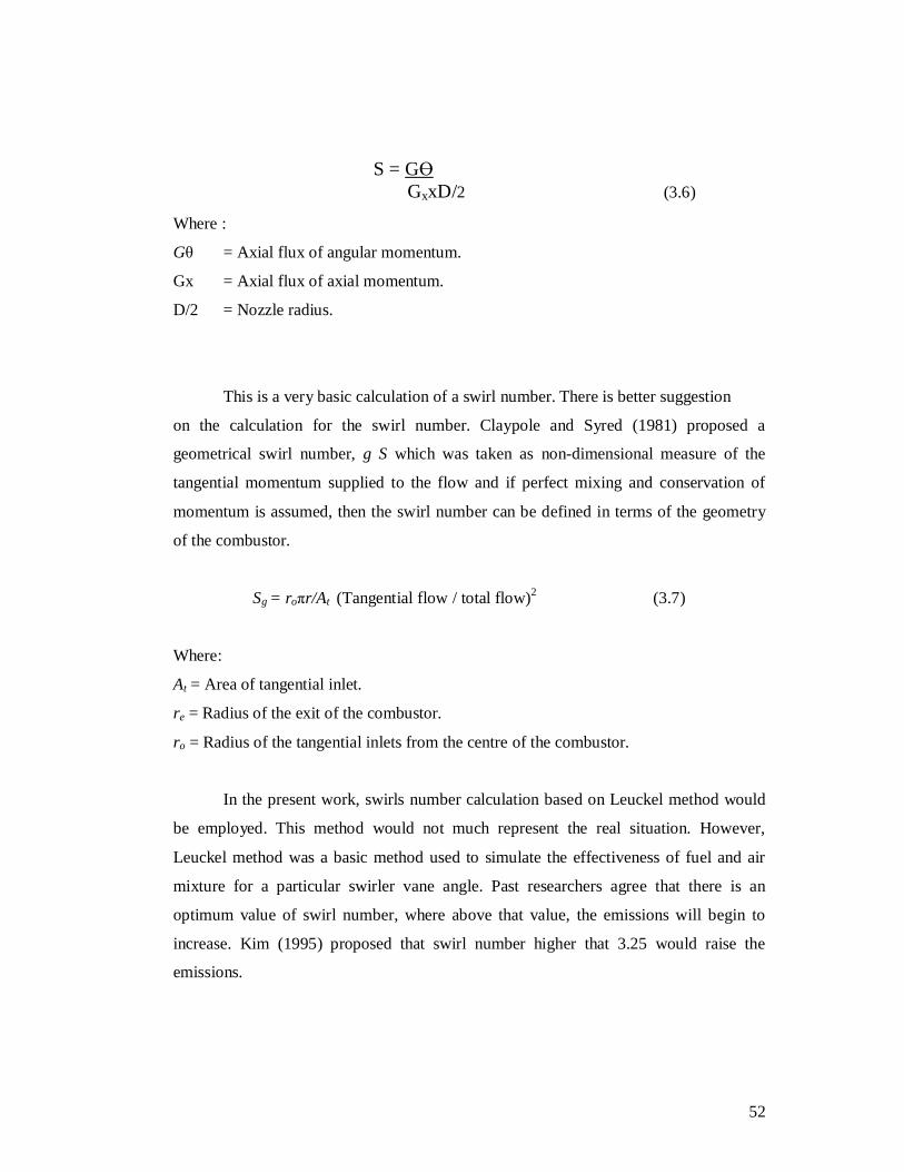
S = GӨ GxxD/2 (3.6)
Where :
Gθ = Axial flux of angular momentum.
Gx = Axial flux of axial momentum.
D/2 = Nozzle radius.
This is a very basic calculation of a swirl number. There is better suggestion
on the calculation for the swirl number. Claypole and Syred (1981) proposed a
geometrical swirl number, g S which was taken as non-dimensional measure of the
tangential momentum supplied to the flow and if perfect mixing and conservation of
momentum is assumed, then the swirl number can be defined in terms of the geometry
of the combustor.
Sg = roπr/At (Tangential flow / total flow)2 (3.7)
Where:
At = Area of tangential inlet.
re = Radius of the exit of the combustor.
ro = Radius of the tangential inlets from the centre of the combustor.
In the present work, swirls number calculation based on Leuckel method would
be employed. This method would not much represent the real situation. However,
Leuckel method was a basic method used to simulate the effectiveness of fuel and air
mixture for a particular swirler vane angle. Past researchers agree that there is an
optimum value of swirl number, where above that value, the emissions will begin to
increase. Kim (1995) proposed that swirl number higher that 3.25 would raise the
emissions.
53
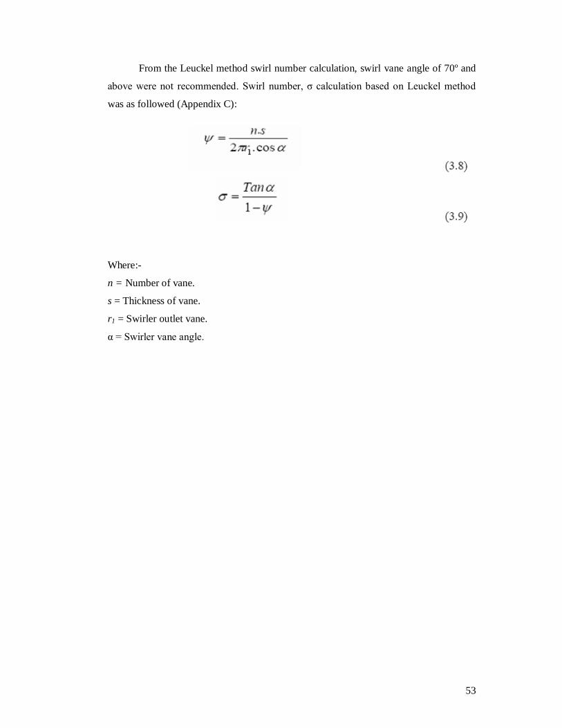
From the Leuckel method swirl number calculation, swirl vane angle of 70º and
above were not recommended. Swirl number, σ calculation based on Leuckel method
was as followed (Appendix C):
Where:-
n = Number of vane.
s = Thickness of vane.
r1 = Swirler outlet vane.
α = Swirler vane angle.