gas-to-steam humidifier - · pdf filegts® vapor-logic ® controller with: †...
TRANSCRIPT

GTS®
Vapor-logic ® controller with:
• Web-enabled remote access
• Modbus ®, BACnet ®, and LonTalk ®
interoperability
Gas- to -Steam Humidi f ier
2 GTS GAS HUMIDIFIER
• 8 capacities from 75–600 lbs/hr (34–272 kg/h)
• Easy fi rmware updates through the USB port on the Vapor-logic board
• View operational data from the keypad or from the Web interface
• Accurate, responsive, adjustable RH control due to full burner modulation and PID control
• Capacity range up to 9,600 lbs/hr (4,352 kg/h) (16 units under one controller)
FEATURES OF THE BEST-SELLING GAS-TO-STEAM HUMIDIFIER
• Automatically cools discharged hot water to 140 °F (60 °C) to meet governing code safety requirements
• Enclosures for virtually any environment. Indoor and outdoor; factory-installed
• Space conscious and streamlined. All humidifi er components are contained within enclosures — no separate control cabinets or wiring subpanels
• Full service access. Lift-off panels provide easy access to all connection points
GA
S
ELEC
TRICITY
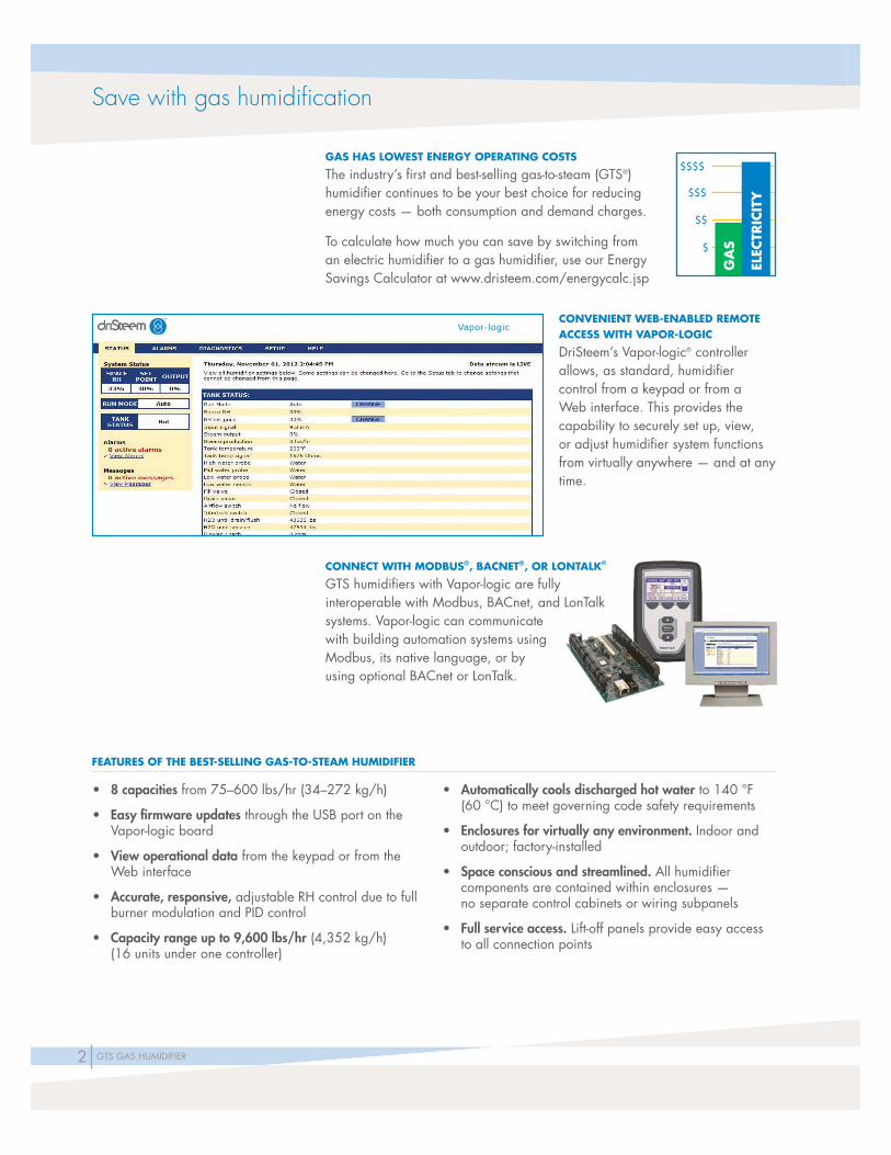
CONVENIENT WEB-ENABLED REMOTE ACCESS WITH VAPOR-LOGIC
DriSteem’s Vapor-logic® controller allows, as standard, humidifi er control from a keypad or from a Web interface. This provides the capability to securely set up, view, or adjust humidifi er system functions from virtually anywhere — and at any time.
GAS HAS LOWEST ENERGY OPERATING COSTS
The industry’s fi rst and best-selling gas-to-steam (GTS®) humidifi er continues to be your best choice for reducing energy costs — both consumption and demand charges.
To calculate how much you can save by switching from an electric humidifi er to a gas humidifi er, use our Energy Savings Calculator at www.dristeem.com/energycalc.jsp
CONNECT WITH MODBUS®, BACNET®, OR LONTALK®
GTS humidifi ers with Vapor-logic are fully interoperable with Modbus, BACnet, and LonTalk systems. Vapor-logic can communicate with building automation systems using Modbus, its native language, or by using optional BACnet or LonTalk.
Vapor-logic
GA
S
ELEC
TRIC
ITY
ONTALK®KK
LonTalk
Save with gas humidifi cation

3GTS GAS HUMIDIFIER
More GTS features and benefi ts
PROVEN PERFORMANCE• Control to ±3% RH
• Steam output rangeability up to 40:1
• Low nitrogen oxide (NOx) emissions of less than 20 ppm
• On-board diagnostics verify system operation
• Up to 84% burner effi ciency rating
• Variable-speed blowers and modulating gas valves provide consistent humidity output
• Designed and tested to meet ARI-640 humidifi cation standard
APPLICATION FLEXIBILITY• Capacity range to 600 lbs/hr (272 kg/h) for each unit; link up to 16 units
for capacity to 9,600 lbs/hr (4,352 kg/h)
• Supports all water types: tap, softened, reverse osmosis, or deionized; easy to fi eld convert if water type changes
• Supports natural and LP gas
• Outdoor enclosure available for outdoor operation in any climate
• CSA/AGA/CGA approved for sealed combustion
• Requires only two-sided access, allowing installation in tight spaces
• Horizontal or vertical venting
• Uses affordable Category 1 venting materials for all options, including sealed combustion
MINIMAL MAINTENANCE• Cleanout plate and removable panels provide easy access for inspection
and servicing
• Use of softened water signifi cantly reduces maintenance requirements
• End-of-season autodrain minimizes microbial growth
• Controller-operated drain and fl ush removes precipitated minerals from evaporating chamber
• Easy water level control access
BUILT-IN SAFETY• CSA/AGA/CGA certifi ed design
• Self-contained infrared gas burners provide safety and reliability
• Gas valves close if the fl ue becomes blocked, shutting down humidifi er operation
• Low-water sensing mechanism with redundant backup shuts down burners in a low water condition
• Can be vented with other Category 1 appliances
• Can interlock with combustion air dampers
• Freeze protection
Next generation control with Vapor-logicThe heart of any humidifi cation system is its controller. See the next page for the features and benefi ts of this controller.
Brave the cold with our heated/ventilated outdoor enclosureThird-party testers verifi ed that cold temperatures are a breeze for our outdoor enclosures, proven to provide reliable operation under extreme conditions. See Pages 12-13 for more information.
Save even more energy with our High-Efficiency Tube optionAn option for new and existing Ultra-sorb® and Rapid-sorb® dispersion assemblies, High-Effi ciency Tubes provide signifi cant energy savings: Wasted energy is reduced by up to 85%. Airstream heat gain and condensate are also signifi cantly lowered. See Pages 16-17 for more information.
DriSteem dispersion: Proven and guaranteedWhen it comes to absorption performance, competitors don't come close to DriSteem’s proven and guaranteed dispersion systems. Defi ne your dispersion requirements and DriSteem will meet or exceed them. Guaranteed. See Pages 16-23 for more dispersion information.
4 GTS GAS HUMIDIFIER
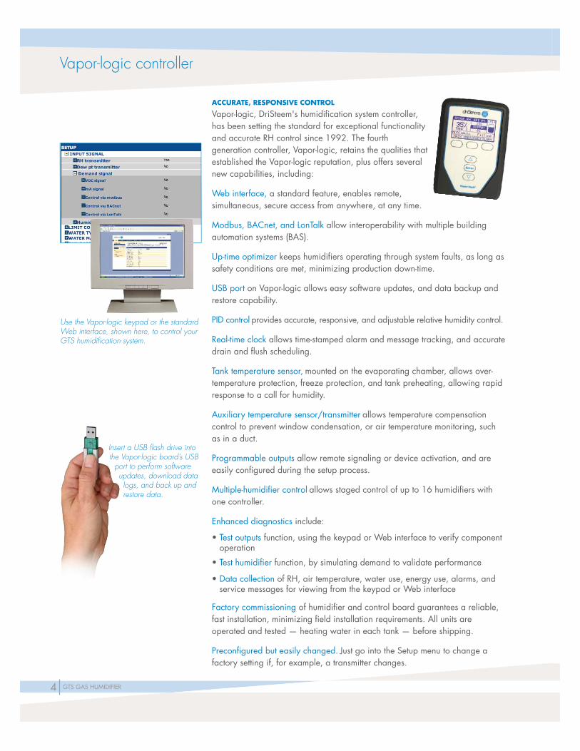
ACCURATE, RESPONSIVE CONTROL
Vapor-logic, DriSteem's humidifi cation system controller, has been setting the standard for exceptional functionality and accurate RH control since 1992. The fourth generation controller, Vapor-logic, retains the qualities that established the Vapor-logic reputation, plus offers several new capabilities, including:
Web interface, a standard feature, enables remote, simultaneous, secure access from anywhere, at any time.
Modbus, BACnet, and LonTalk allow interoperability with multiple building automation systems (BAS).
Up-time optimizer keeps humidifi ers operating through system faults, as long as safety conditions are met, minimizing production down-time.
USB port on Vapor-logic allows easy software updates, and data backup and restore capability.
PID control provides accurate, responsive, and adjustable relative humidity control.
Real-time clock allows time-stamped alarm and message tracking, and accurate drain and fl ush scheduling.
Tank temperature sensor, mounted on the evaporating chamber, allows over-temperature protection, freeze protection, and tank preheating, allowing rapid response to a call for humidity.
Auxiliary temperature sensor/transmitter allows temperature compensation control to prevent window condensation, or air temperature monitoring, such as in a duct.
Programmable outputs allow remote signaling or device activation, and are easily confi gured during the setup process.
Multiple-humidifi er control allows staged control of up to 16 humidifi ers with one controller.
Enhanced diagnostics include:
• Test outputs function, using the keypad or Web interface to verify component operation
• Test humidifi er function, by simulating demand to validate performance
• Data collection of RH, air temperature, water use, energy use, alarms, and service messages for viewing from the keypad or Web interface
Factory commissioning of humidifi er and control board guarantees a reliable, fast installation, minimizing fi eld installation requirements. All units are operated and tested — heating water in each tank — before shipping.
Preconfi gured but easily changed. Just go into the Setup menu to change a factory setting if, for example, a transmitter changes.
Vapor-logic controller
Use the Vapor-logic keypad or the standard Web interface, shown here, to control your GTS humidifi cation system.
Insert a USB fl ash drive into the Vapor-logic board’s USB
port to perform software updates, download data logs, and back up and restore data.

5GTS GAS HUMIDIFIER
GTS PRINCIPLE OF OPERATION
OM-7468
2
3
4
1
4
1 When the GTS humidifi er is fi rst activated, the fi ll valve opens and the evaporating chamber fi lls with water to the operating level.
2 On a call for humidity, the infrared burner(s) ignite(s) sequentially. After all burners are fi ring into the heat exchanger, the blowers ramp up to bring burners to maximum output until the water in the evaporating chamber boils. The burners then begin to modulate based on demand. The fi ll valve opens and closes as needed to maintain the operating water level.
3 Steam created in the evaporating chamber fl ows through steam hose or piping to the dispersion assembly, where it is discharged into the airstream.
4 The products of combustion are vented out the fl ute.
GTS principle of operation

6 GTS GAS HUMIDIFIER
1
2
3
4 5
7
8
910
12
116
GTS components
1 Vapor-logic controller(keypad and web interface not shown)Vapor-logic controls all humidifi er functions as a stand-alone controller or integrated into a Modbus, BACnet, or LonTalk system.
2 Water level controlTap or softened water systems control water levels electronically using a three-rod probe. DI/RO water systems control water levels using a fl oat valve and a low-water cutoff switch.
3 Redundant water sensorThe redundant water sensor provides a safety to the main water level sensor to prevent operation if water is not covering the heat exchanger tubes.
4 Water tempering deviceThis factory-installed water-tempering device automatically cools discharged hot water to 140 °F (60 °C) to meet governing code requirements for safe discharge water temperature. Cooling discharged hot water also prevents damage to PVC drain piping (see Figure 7-1).
Fill valve opens when water level is below this probe.
Low-water cutoff. Power to heaters is cut if water level drops below this probe.
Fill valve closes when water level rises to this probe.
WATER LEVEL CONTROL FOR TAP/SOFTENED WATER HUMIDIFIER
VLC-OM-030mc_030910_1225
Humidifi ers using tap or softened water control water levels electronically using a three-rod probe. The controller responds with the above actions when the water level reaches each rod.
WATER LEVEL CONTROL FOR DI/RO WATER SYSTEMS
Fill valve
Float rod
Float ballVLC_OM_026
GTS COMPONENTS
OM-7469
PROBE ACCESS (WITH COVER OPEN)
7GTS GAS HUMIDIFIER
GTS components
5 DrainDrain duration and frequency can be adjusted through the keypad or web interface To avoid possible stagnant water and microbial growth, the humidifi er automatically drains if there is no call for humidity after a user-defi ned time period (72-hour default).
6 Auxiliary drainThis 1½ (DN 40) outlet provides an additional location for draining the tank.
7 Water skimmer/overfl ow portIn standard water systems, the water skimmer reduces minerals in the evaporating chamber. Skimming occurs each time the humidifi er fi lls. The skim time duration is user-adjustable. DI/RO water systems do not require skimming The skimmer port also functions as an overfl ow port.
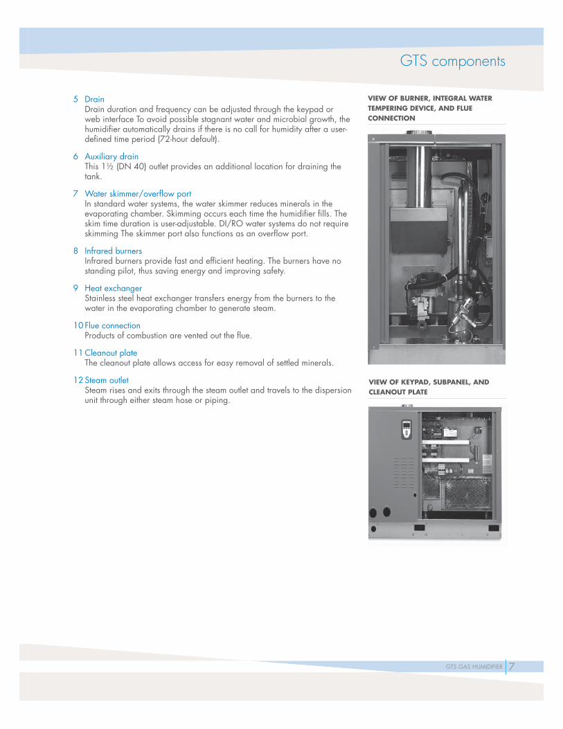
8 Infrared burnersInfrared burners provide fast and effi cient heating. The burners have no standing pilot, thus saving energy and improving safety.
9 Heat exchangerStainless steel heat exchanger transfers energy from the burners to the water in the evaporating chamber to generate steam.
10 Flue connectionProducts of combustion are vented out the fl ue.
11 Cleanout plateThe cleanout plate allows access for easy removal of settled minerals.
12 Steam outletSteam rises and exits through the steam outlet and travels to the dispersion unit through either steam hose or piping.
VIEW OF BURNER, INTEGRAL WATER TEMPERING DEVICE, AND FLUE CONNECTION
VIEW OF KEYPAD, SUBPANEL, AND CLEANOUT PLATE

8 GTS GAS HUMIDIFIER
Table 8-1:GTS specifications, capacities, and weights
Model Number
of burners
Maximumsteam
capacity Input
Water usage at maximum capacity*
Tankvolume
GTS GTS with outdoor enclosure Full load amps**Operating
weightShipping weight
Operating weight
Shipping weight
lbs/hr kg/h MBh kW gals/hr litres/hr gals litres lbs kg lbs kg lbs kg lbs kg 120 V
60 Hz
GTS-100 1 75 34 100 29 9 34.1 49 185.5 700 320 375 170 800 365 500 230 1.8
GTS-200 1 150 68 200 59 18 68.1 49 185.5 700 320 375 170 800 365 500 230 1.8
GTS-300 2 225 102 300 88 27 102.2 53 200.6 850 385 450 205 1000 455 600 270 3.0
GTS-400 2 300 136 400 117 36 136.3 53 200.6 850 385 450 205 1000 455 600 270 3.0
GTS-500 3 375 170 500 147 45 170.3 76 287.7 1100 500 600 270 1450 660 950 430 4.5
GTS-600 3 450 204 600 176 54 204.4 76 287.7 1100 500 600 270 1450 660 950 430 4.5
GTS-700 4 525 238 700 205 63 238.5 89 336.9 1400 635 700 320 1750 795 1050 475 6.0
GTS-800 4 600 272 800 234 72 272.5 89 336.9 1400 635 700 320 1750 795 1050 475 6.0
* Add 10% to account for skim and automatic drain/fl ush features if utilized (tap/softened water units only).** Add 15 full load amps for outdoor enclosure heater load on all GTS models, add 1 full load amp for an outdoor enclosure without heaters.
GTS specifi cations, capacities, and weights
Table 8-2:High altitude derate
AltitudeInput derate %
feet meters
0-2000 0-610 0
2001-2500 610-765 2*
2501-3000 765-915 4*
3001-3500 915-1065 6*
3501-4000 1065-1220 8*
4001-4500 1220-1370 10
4501-5000 1370-1525 12
5001-5500 1525-1675 14
5501-6000 1675-1830 16
6001-6500 1830-1980 18
6501-7000 1980-2135 20
7001-7500 2135-2285 22
7501-8000 2285-2440 24
CAPACITY NOTES• At sea level, approximately 152 BTUs are required to
raise one pound of water from 60°F to 212°F. (At sea level, approximately 352 kJ are required to raise one kilogram of water from 16°C to 100°C).
• An additional 970 BTUs are required to change the state of one pound of 212°F water to vapor. (An additional 2257 kJ are required to change the state of one kilogram of 100°C water to vapor).
• Another factor to consider is condensation steam loss from piping. Use the following general steam loss guidelines:- Steam hose: 0.15 lbs/hr/ft (0.22 kg/h/m)- Insulated pipe: 0.05 lbs/hr/ft (0.07 kg/h/m)- High-Effi ciency Dispersion Tubes: 0.20 lbs/hr/ft (0.298 kg/h/m)
For more detailed information about condensation steam loss, see the DriSteem design guide or our software program, Dri-calc.
LP GASAll models operate at rated MBh/kW input.
HIGH ALTITUDE
A derate in MBh/kW input exists when operating units at high altitude. See Table 8-2 for high altitude derate information.
* GTS-400 models are derated 10% from 2001-4500 ft. in Canada.
9GTS GAS HUMIDIFIER
J
E
F
D
G
C
K
A
H
L
M
5" (127 mm)
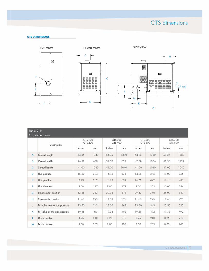
GTS dimensions
GTS DIMENSIONS
Table 9-1: GTS dimensions
Description
GTS-100GTS-200
GTS-300GTS-400
GTS-500GTS-600
GTS-700GTS-800
inches mm inches mm inches mm inches mm
A Overall length 54.35 1380 54.35 1380 54.35 1380 54.35 1380
B Overall width 26.38 670 32.38 822 42.38 1076 48.38 1229
C Shroud height 41.00 1040 41.00 1040 41.00 1040 41.00 1040
D Flue position 15.50 394 14.75 375 14.95 375 14.00 356
E Flue position 9.13 232 13.13 334 16.63 422 19.13 486
F Flue diameter 5.00 127 7.00 178 8.00 203 10.00 254
G Steam outlet position 13.88 353 20.38 518 29.13 740 35.00 889
H Steam outlet position 11.63 295 11.63 295 11.63 295 11.63 295
J Fill valve connection position 13.50 343 13.50 343 13.50 343 13.50 343
K Fill valve connection position 19.38 492 19.38 492 19.38 492 19.38 492
L Drain position 8.25 210 8.25 210 8.25 210 8.25 210
M Drain position 8.00 203 8.00 203 8.00 203 8.00 203
TOP VIEW
B
FRONT VIEW SIDE VIEW
10 GTS GAS HUMIDIFIER
4" dia. (DN100) PVC or CPVC combustion air intake
OM-1225
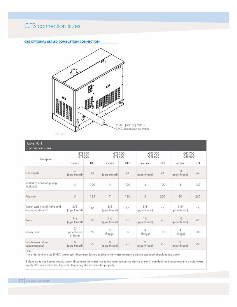
GTS connection sizes
GTS OPTIONAL SEALED COMBUSTION CONNECTION
Table 10-1: Connection sizes
Description
GTS-100GTS-200
GTS-300GTS-400
GTS-500GTS-600
GTS-700GTS-800
inches DN inches DN inches DN inches DN
Gas supply ½(pipe thread) 15 1
(pipe thread) 25 1(pipe thread) 25 1¼
(pipe thread) 32
Sealed combustion piping (optional) 4 100 4 100 4 100 4 100
Flue vent 5 125 7 180 8 200 10 250
Water supply to fi ll valve and tempering device*
3/8(pipe thread) 10 3/8
(pipe thread) 10 3/8(pipe thread) 10 3/8
(pipe thread) 10
Drain 1½(pipe thread) 40 1½
(pipe thread) 40 1½(pipe thread) 40 1½
(pipe thread) 40
Steam outlet2
(pipe thread or hose)
50 3(fl ange) 80 4
(fl ange) 100 4(fl ange) 100
Condensate return (recommended)
¾(pipe thread) 20 ¾
(pipe thread) 20 ¾(pipe thread) 20 ¾
(pipe thread) 20
Notes:* In order to minimize DI/RO water use, disconnect factory piping to the water tempering device and pipe directly to tap water.
If planning to use heated supply water, disconnect the water line to the water tempering device at the fi ll manifold, and reconnect it to a cold water supply. This will ensure that the water tempering device operates properly.

11GTS GAS HUMIDIFIER
OM-7474
18" (457 mm)
36" (914 mm)
30" (762 mm)
Note:DriSteem recommends a minimum of 1" (25 mm) clearance between hot surfaces and combustible materials.
GTS CLEARANCE RECOMMENDATIONS
OM-1222
MOUNTING
The GTS is available in two mounting confi gurations:
• Indoor installations: The humidifi er is factory-installed in a painted enclosure with integral base.
• Outdoor installations: The humidifi er is factory-installed in a galvanized steel enclosure with integral base and includes heaters and ventilation fans. The outdoor enclosure may also be ordered without the heater package, or with a factory-supplied roof curb.
GTS mounting
GTS ONLY REQUIRES TWO-SIDED ACCESS

12 GTS GAS HUMIDIFIER
HEATED AND VENTILATED OUTDOOR ENCLOSURE
DriSteem offers a robust and affordable enclosure for mounting the GTS humidifi er outdoors. Independent testing has proven that the GTS installed within this new outdoor enclosure provides error-free ignition and reliable operation under extreme conditions.
OUTDOOR ENCLOSURE FEATURES• Protects in cold and hot climates. To ensure complete
safety and operation in all climates, the outdoor enclosure has heating and venting systems that ensure humidifi er operation in temperatures from -40°F (-40°C) to 120°F (48°C). The outdoor enclosure can also be ordered without the heater package.
• Install on the ground or roof. The outdoor enclosure is ideal for facilities that have limited interior space.
• Factory constructed. The outdoor enclosure ships complete with a GTS unit pre-installed and tested, ready to easily connect to gas, water, steam, and electricity.
• Certifi ed, tested and proven. GTS humidifi ers and outdoor enclosures are CSA/AGA/CGA certifi ed for outdoor operation. In addition, in-house testing has proven that the GTS and outdoor enclosure provide error-free ignition and reliable operation under extreme conditions.
• Easy service access. Easily removed panels provide access to all internal components.
• Robust design. The outdoor enclosure is ruggedly built to completely protect internal components. The enclosure is constructed of heavy-duty galvanized steel and is fully insulated. Serviceable gaskets on access panels ensure a tight seal.
• Optional curb. Factory-supplied curb provides base clearance and allows easy installation.
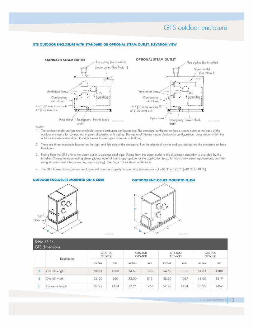
GTS outdoor enclosure
GTS OUTDOOR ENCLOSURE
The outdoor enclosure has heating and venting systems that ensure humidifi er operation in temperatures from -40°F (-40°C) to 120°F (48°C). The outdoor enclosure can also be ordered without the heater package, or with a factory-supplied curb.
13GTS GAS HUMIDIFIER
Notes:1. The outdoor enclosure has two available steam distribution confi gurations. The standard confi guration has a steam outlet at the back of the
outdoor enclosure for connecting to steam dispersion unit piping. The optional internal steam distribution confi guration routes steam within the outdoor enclosure and down through the enclosure pipe chase into a building.
2. There are three knockouts located on the right and left side of the enclosure. Run the electrical power and gas piping into the enclosure at these knockouts.
3. Piping from the GTS unit to the steam outlet is stainless steel pipe. Piping from the steam outlet to the dispersion assembly is provided by the installer. Choose interconnecting steam piping material that is appropriate for the application (e.g., for high-purity steam applications, consider using stainless steel interconnecting steam piping). See Page 10 for steam outlet sizes.
4. The GTS housed in an outdoor enclosure will operate properly in operating temperatures of –40 °F to 120 °F (–40 °C to 48 °C).
Flue piping (by installer)
Ventilation fans
1½" (38 mm) knockouts4" (102 mm) o.c.
Steam outlet (See Note 1)
OM-1227M
GTS humidifi er
Steam outlet (See Note 1)
Combustionair intake
Flue piping (by installer)
Ventilation fans
Power block
1½" (38 mm) knockouts4" (102 mm) o.c.
Emergencydrain
Pipe chase OM-1228M
GTS humidifi er
Power blockEmergencydrain
Pipe chase
Combustionair intake
OM-7431
14"(356 mm)
CB
OM-7430
A
BC
GTS outdoor enclosure
GTS OUTDOOR ENCLOSURE WITH STANDARD OR OPTIONAL STEAM OUTLET, ELEVATION VIEW
STANDARD STEAM OUTLET OPTIONAL STEAM OUTLET
OUTDOOR ENCLOSURE MOUNTED ON A CURB OUTDOOR ENCLOSURE MOUNTED FLUSH
Table 13-1: GTS dimensions
Description
GTS-100GTS-200
GTS-300GTS-400
GTS-500GTS-600
GTS-700GTS-800
inches mm inches mm inches mm inches mm
A Overall length 54.63 1388 54.63 1388 54.63 1388 54.63 1388
B Overall width 26.00 660 32.00 813 42.00 1067 48.00 1219
C Enclosure length 57.25 1454 57.25 1454 57.25 1454 57.25 1454

14 GTS GAS HUMIDIFIER
OM-1208
Flue size per governing codes. Do not reduce.
Water supply line; water pressure range 25 psi to 80 psi (172 kPa to 582 kPa); water conductivity minimum 100 µS/cm
Shock arrester recommended to reduce water hammer, by installer
Flue connection
Gas inlet connection1" (25 mm) air gap
Open drain required. See fi rst note below.
1½" NPT (DN40) drain piping must be rated for 212 °F (100 °C) (by installer)
Install level
Optional condensate return piping from dispersion unit; ¾" pipe thread (DN20) fi tting
at humidifi er
Air vent height must be equal to or greater than dimension “H” (see table below)
Steam hose, pipe or tubing
H
Offset humidifi er from fl oor drain to prevent fl ash steam from rising into the humidifi er
Air vent tube
6" (150 mm) minimum vent height
Install level
GTS piping, standard water models
FIELD PIPING OVERVIEW FOR GTS STANDARD WATER MODELS
Table 14-1: Height required to overcome GTS internal pressure (H)
GTS model numberH = Height required to overcome humidifi er internal pressure
inches mm
100, 200 35 889
300, 400, 500, 600, 700, 800 41 1041
Notes:• Locate air gap only in spaces with adequate temperature and air movement to absorb fl ash steam; otherwise, condensation may form on nearby
surfaces. Refer to governing codes for drain pipe size and maximum discharge water temperature.
• Dashed lines indicate provided by installer.
• Humidifi er fl ue gases must be vented to the outside atmosphere.
• The water supply inlet is more than 1" (25 mm) above the skim/overfl ow port, eliminating the possibility of backfl ow or siphoning from the tank. No additional backfl ow prevention is required; however, governing codes prevail.
• Damage caused by chloride corrosion is not covered by your DriSteem warranty.
• See the next page for recommended water supply piping for DI/RO water models.

15GTS GAS HUMIDIFIER
OM-1223
Notes:• Locate air gap only in spaces with adequate temperature and air movement to absorb fl ash steam; otherwise, condensation may form on nearby
surfaces. Refer to governing codes for drain pipe size and maximum discharge water temperature.
• Dashed lines indicate provided by installer.
• Humidifi er fl ue gases must be vented to the outside atmosphere.
• The water supply inlet is more than 1" (25 mm) above the overfl ow port, eliminating the possibility of backfl ow or siphoning from the tank. No additional backfl ow prevention is required; however, governing codes prevail.
• Damage caused by chloride corrosion is not covered by your DriSteem warranty.
• In order to minimize DI/RO water use, disconnect factory piping to the water tempering device and pipe directly to tap water.
• See the previous page for recommended water supply piping for standard water models.
Water supply line; water pressure range 25 psi to 80 psi (172 kPa to 582 kPa); fi rst 3' (1 m) of supply line must be rated for 212 °F (100 °C)
Flue connection
Gas inlet connection1" (25 mm) air gap
1½" (DN40) drain piping must be rated for 212 °F (100 °C)
Install level
Air vent tube height must be equal to or greater than dimension “H“ (see table below)
Steam hose, pipe or tubing
Install level
If water piping to humidifi er is nonmetallic, we recommend a 2" (50 mm) water seal in the supply line to isolate steam during DI/RO water system maintenance.
Offset humidifi er from fl oor drain to prevent fl ash steam from rising into the humidifi er
H
Inlet strainer by installer
6" (150 mm) minimum vent height
Open drain required. See fi rst note below.
Air vent tube
Optional condensate return piping from dispersion unit; ¾" pipe thread (DN20) fi tting at humidifi er
Flue size per governing codes. Do not reduce.
Table 15-1: Height required to overcome GTS-DI internal pressure (H)
GTS-DI model numberH = Height required to overcome humidifi er internal pressure
inches mm
100, 200 35 889
300, 400, 500, 600, 700, 800 41 1041
GTS piping, DI/RO water models
FIELD PIPING OVERVIEW FOR GTS DI/RO WATER MODELS
16 GTS GAS HUMIDIFIER
Drip-free dispersion basics and options
GUARANTEED NON-WETTING DISTANCES
Using data collected in our on-site test laboratories, we have developed guaranteed steam absorption (non-wetting) distances, allowing you to confi dently choose equipment that will accommodate any application.
DRY STEAM
Adding humidifi cation to an airstream without creating wetness in the duct system is critical for the maintenance of a healthy environment. Wet areas in ducts are a threat to the health of building occupants since they moisten dust on duct fl oors, creating ideal breeding grounds for disease-producing microbes. In addition, water accumulating in ducts can drip and cause building damage.
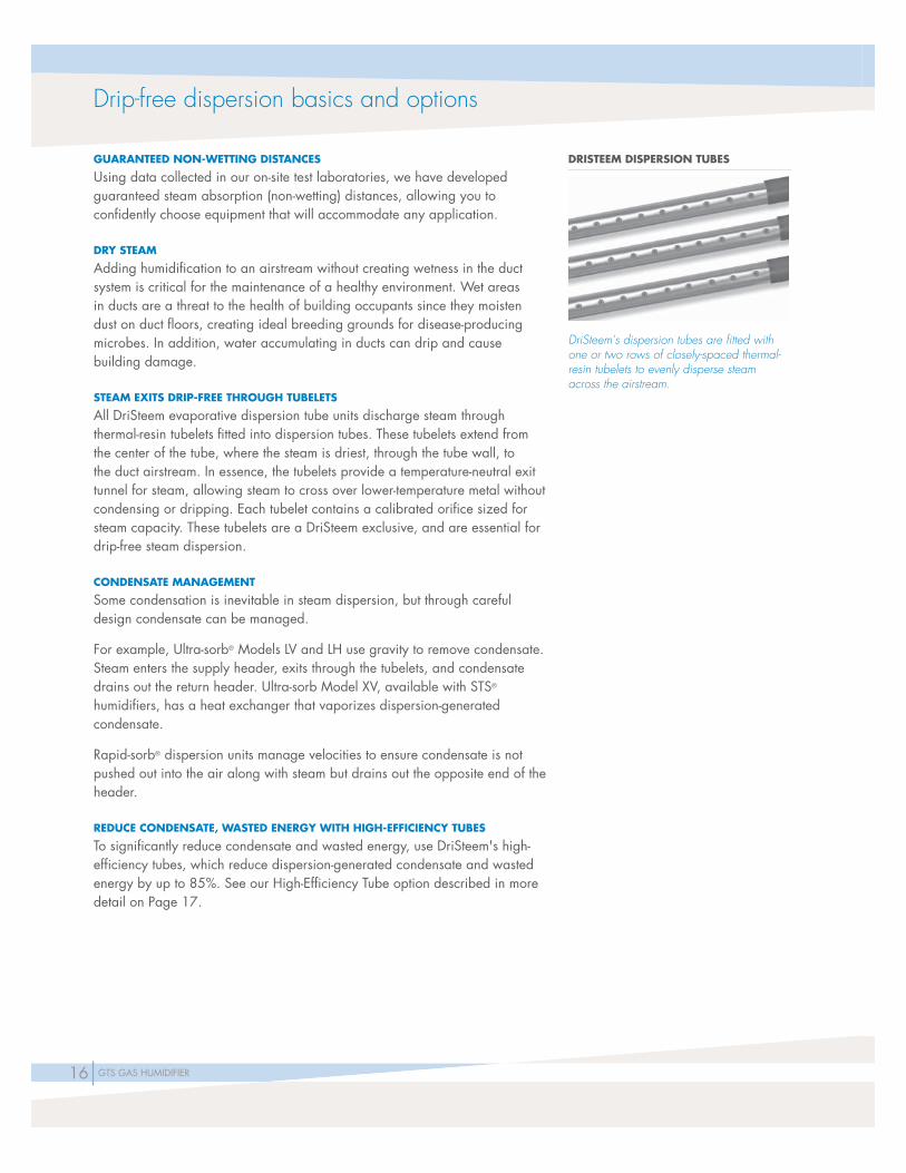
STEAM EXITS DRIP-FREE THROUGH TUBELETS
All DriSteem evaporative dispersion tube units discharge steam through thermal-resin tubelets fi tted into dispersion tubes. These tubelets extend from the center of the tube, where the steam is driest, through the tube wall, to the duct airstream. In essence, the tubelets provide a temperature-neutral exit tunnel for steam, allowing steam to cross over lower-temperature metal without condensing or dripping. Each tubelet contains a calibrated orifi ce sized for steam capacity. These tubelets are a DriSteem exclusive, and are essential for drip-free steam dispersion.
CONDENSATE MANAGEMENT
Some condensation is inevitable in steam dispersion, but through careful design condensate can be managed.
For example, Ultra-sorb® Models LV and LH use gravity to remove condensate. Steam enters the supply header, exits through the tubelets, and condensate drains out the return header. Ultra-sorb Model XV, available with STS® humidifi ers, has a heat exchanger that vaporizes dispersion-generated condensate.
Rapid-sorb® dispersion units manage velocities to ensure condensate is not pushed out into the air along with steam but drains out the opposite end of the header.
REDUCE CONDENSATE, WASTED ENERGY WITH HIGH-EFFICIENCY TUBES
To significantly reduce condensate and wasted energy, use DriSteem's high-efficiency tubes, which reduce dispersion-generated condensate and wasted energy by up to 85%. See our High-Efficiency Tube option described in more detail on Page 17.
DRISTEEM DISPERSION TUBES
DriSteem's dispersion tubes are fi tted with one or two rows of closely-spaced thermal-resin tubelets to evenly disperse steam across the airstream.

17GTS GAS HUMIDIFIER
ULTRA-SORB MODELS LV AND LH
Most versatile
• Guaranteed, short non-wetting distances --- install within inches of downstream devices
• Reduce wasted energy up to 85% and increase capacity with optional High-Effi ciency Dispersion Tubes
• Lowest installation cost --- factory assembly for easy installation
Capacity:Up to 1850 lbs/hr (840 kg/h) per panel
HIGH-EFFICIENCY DISPERSION TUBES OPTIONS
For new and existing Ultra-sorb, Rapid-sorb, single dispersion tube
• Highest effi ciency
• Increases tube capacity up to 6 lbs/hr (2.7 kg/h)
• Up to 85% reduction in wasted energy, airstream heat gain, and condensate production
• Plenum approved for in-duct installation
GTS steam dispersion options
ULTRA-SORB MODELS LV
ULTRA-SORB MODEL LH
ULTRA-SORB MODEL LV WITH HIGH-EFFICIENCY TUBES
RAPID-SORB WITH HIGH-EFFICIENCY TUBES
18 GTS GAS HUMIDIFIER
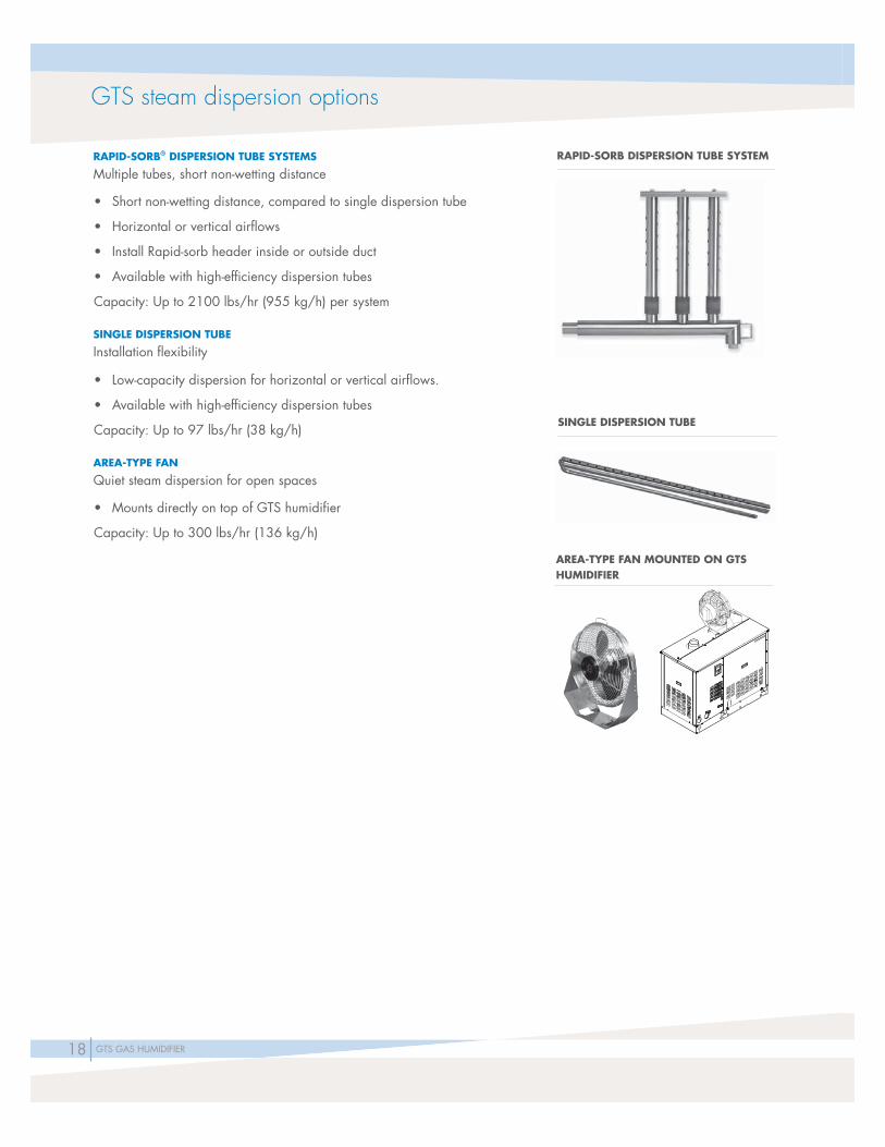
GTS steam dispersion options
RAPID-SORB® DISPERSION TUBE SYSTEMS
Multiple tubes, short non-wetting distance
• Short non-wetting distance, compared to single dispersion tube
• Horizontal or vertical airfl ows
• Install Rapid-sorb header inside or outside duct
• Available with high-effi ciency dispersion tubes
Capacity: Up to 2100 lbs/hr (955 kg/h) per system
SINGLE DISPERSION TUBE
Installation fl exibility
• Low-capacity dispersion for horizontal or vertical airfl ows.
• Available with high-effi ciency dispersion tubes
Capacity: Up to 97 lbs/hr (38 kg/h)
AREA-TYPE FAN
Quiet steam dispersion for open spaces
• Mounts directly on top of GTS humidifi er
Capacity: Up to 300 lbs/hr (136 kg/h)
RAPID-SORB DISPERSION TUBE SYSTEM
SINGLE DISPERSION TUBE
AREA-TYPE FAN MOUNTED ON GTS HUMIDIFIER
19GTS GAS HUMIDIFIER
TOP VIEW
E
G
Condensate header
ELEVATION VIEW
Dispersion tubes
SIDE VIEW
Header
AD
B
G A'
E
G
C
F
B'
H
E
Supply header
Header
OM-123mc_062711_1425
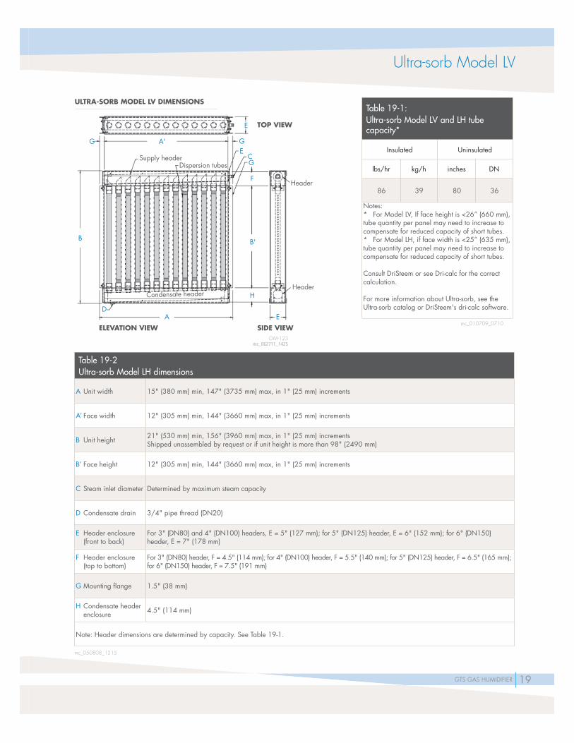
Ultra-sorb Model LV
Table 19-2Ultra-sorb Model LH dimensions
A Unit width 15" (380 mm) min, 147" (3735 mm) max, in 1" (25 mm) increments
A’ Face width 12" (305 mm) min, 144" (3660 mm) max, in 1" (25 mm) increments
B Unit height 21" (530 mm) min, 156" (3960 mm) max, in 1" (25 mm) incrementsShipped unassembled by request or if unit height is more than 98" (2490 mm)
B’ Face height 12" (305 mm) min, 144" (3660 mm) max, in 1" (25 mm) increments
C Steam inlet diameter Determined by maximum steam capacity
D Condensate drain 3/4" pipe thread (DN20)
E Header enclosure (front to back)
For 3" (DN80) and 4" (DN100) headers, E = 5" (127 mm); for 5" (DN125) header, E = 6" (152 mm); for 6" (DN150) header, E = 7" (178 mm)
F Header enclosure (top to bottom)
For 3" (DN80) header, F = 4.5" (114 mm); for 4" (DN100) header, F = 5.5" (140 mm); for 5" (DN125) header, F = 6.5" (165 mm); for 6" (DN150) header, F = 7.5" (191 mm)
G Mounting fl ange 1.5" (38 mm)
H Condensate header enclosure 4.5" (114 mm)
Note: Header dimensions are determined by capacity. See Table 19-1.
mc_050808_1215
Table 19-1: Ultra-sorb Model LV and LH tube capacity*
Insulated Uninsulated
lbs/hr kg/h inches DN
86 39 80 36
Notes:* For Model LV, If face height is <26” (660 mm), tube quantity per panel may need to increase to compensate for reduced capacity of short tubes.* For Model LH, if face width is <25” (635 mm), tube quantity per panel may need to increase to compensate for reduced capacity of short tubes.
Consult DriSteem or see Dri-calc for the correct calculation.
For more information about Ultra-sorb, see the Ultra-sorb catalog or DriSteem's dri-calc software.
ULTRA-SORB MODEL LV DIMENSIONS
mc_010709_0710
20 GTS GAS HUMIDIFIER
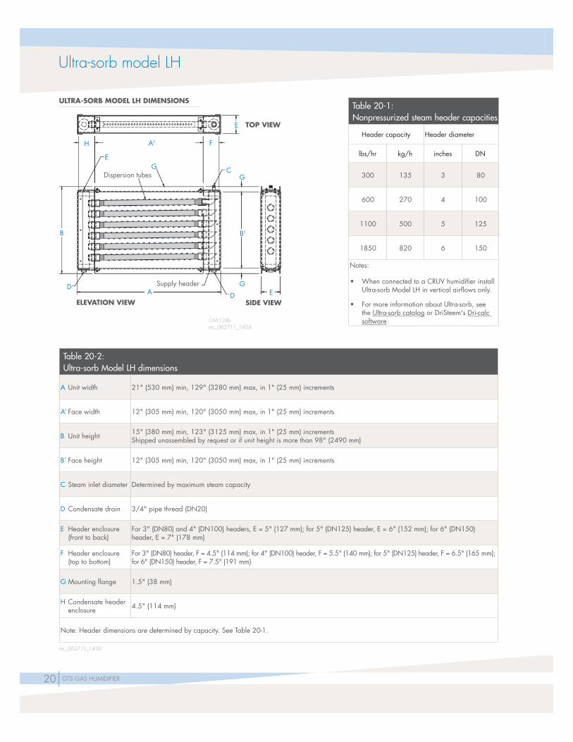
TOP VIEW
A' F
CG
E
EG
D
Supply headerD
B
AELEVATION VIEW SIDE VIEW
B'
H
Dispersion tubes
EG
Table 20-2: Ultra-sorb Model LH dimensions
A Unit width 21" (530 mm) min, 129" (3280 mm) max, in 1" (25 mm) increments
A’ Face width 12" (305 mm) min, 120" (3050 mm) max, in 1" (25 mm) increments
B Unit height 15" (380 mm) min, 123" (3125 mm) max, in 1" (25 mm) incrementsShipped unassembled by request or if unit height is more than 98" (2490 mm)
B’ Face height 12" (305 mm) min, 120" (3050 mm) max, in 1" (25 mm) increments
C Steam inlet diameter Determined by maximum steam capacity
D Condensate drain 3/4" pipe thread (DN20)
E Header enclosure (front to back)
For 3" (DN80) and 4" (DN100) headers, E = 5" (127 mm); for 5" (DN125) header, E = 6" (152 mm); for 6" (DN150) header, E = 7" (178 mm)
F Header enclosure (top to bottom)
For 3" (DN80) header, F = 4.5" (114 mm); for 4" (DN100) header, F = 5.5" (140 mm); for 5" (DN125) header, F = 6.5" (165 mm); for 6" (DN150) header, F = 7.5" (191 mm)
G Mounting fl ange 1.5" (38 mm)
H Condensate header enclosure 4.5" (114 mm)
Note: Header dimensions are determined by capacity. See Table 20-1.
mc_062711_1430
Table 20-1: Nonpressurized steam header capacities
Header capacity Header diameter
lbs/hr kg/h inches DN
300 135 3 80
600 270 4 100
1100 500 5 125
1850 820 6 150
Notes:
• When connected to a CRUV humidifi er install Ultra-sorb Model LH in vertical airfl ows only.
• For more information about Ultra-sorb, see the Ultra-sorb catalog or DriSteem's Dri-calc software.
ULTRA-SORB MODEL LH DIMENSIONS
OM-124bmc_062711_1424
Ultra-sorb model LH

21GTS GAS HUMIDIFIER
Rapid-sorb dimensions
Table 21-1: Rapid-sorb capacities
Tube diameter Insulated (high-effi ciency tubes) Uninsulated
inches DN lbs/hr kg/h lbs/hr kg/h
1½ 40 43 19.5 40 18.2
2 50 80 36.4 77 35
Note:* Capacities shown are for horizontal airfl ow. See Dri-calc for vertical airfl ow capacities. If face height is <22” (559 mm), tube quantity per panel may need to increase to compensate for reduced capacity of short tubes. Consult DriSteem or see Dri-calc for the correct calculation.
Table 21-2: Rapid-sorb dimensions
Dimension Description Inches (mm)
A Face width12" (305) minimum to 120" (3048) maximum in 1" (25) increments
B Face height12" (305) minimum to 120" (3048) maximum in 1" (25) increments
C Steam inlet Determined by humidifi er maximum capacity
D Condensate drain ¾" pipe thread (DN20)
E Distance from tube center to inside of duct or AHU wall 4.5" (114) minimum
FDistance from outside of duct or AHU wall to end of Rapid-sorb leader
4.5" (114) minimum
Note: All Rapid-sorb units are custom-sized and fi eld-assembled to fi t the duct or air handler. Consult DriSteem for sizes larger or smaller than those listed above.
RAPID-SORB DIMENSIONS
1½" (DN40) dia. dispersion tubes use slip coupling
C
Escutcheon plate
2" (DN50) dia. dispersion tubes use hose cuff and clamps
Header outside duct
F Header inside duct or AHU D
Pitch header toward drain
A
E
B
OM-3005
Note:Add water seal to condensate drain as shown in the Dri-calc Installation Guides or the humidifi er’s Installation, Operation, and Maintenance manual.

22 GTS GAS HUMIDIFIER
Single dispersion tube with condensate drain:Recommended pitch toward humidifi er for interconnecting hose, tubing or pipe:• Vapor hose: 2” per ft (15%)• 1½" tubing or pipe: ½" per ft (5%)• 2" tubing or pipe: ¼” per ft (2%)
4.5" (114 mm) minimum from top of duct
4.5" (114 mm) minimum from bottom of duct
Condensate drain. Pitch ¼"/ft (2%)
5" (127 mm)
1" (25 mm) air gap
6"(152 mm)
WITH DRAIN
Dispersion tube pitch2"/ft (15%)
4.5" (114 mm) minimum from top of duct
Hose, tubingor pipe pitch:See Notes
WITHOUT DRAIN
Single dispersion tube without condensate drain:Recommended pitch toward humidifi er for interconnecting hose, tubing or pipe:• Vapor hose: 2" per ft (15%)• Tubing or pipe: 1/8” per ft (1%)
Hose, tubing or pipe pitch:See Notes Dispersion tube pitch 1/8”/ft (1%)
Dristeem steam-generating humidifi er
DriSteemsteam-generating humidifi er
Single dispersion tube
Table 22-1: Single dispersion tube capacities
Tube size
Insulated(High-Effi ciency Tubes) Uninsulated
Without drain With drain Without drain With drain
inches DN lbs/hr kg/h lbs/hr kg/h lbs/hr kg/h lbs/hr kg/h
1½ 40 29 13.2 65 29.5 28 12.7 62 28.2
2 50 65 29.5 97 44.1 62 28.2 93 42.3
Note: Single dispersion tube available with face width between 6" (152 mm) up to 120" (3048 mm) in 1" (25 mm) increments.* If face width is <19" (483 mm), tube capacity may be reduced. Consult DriSteem or see Dri-calc for the correct capacity.
mc_121311_1337
SINGLE DISPERSION TUBE WITHOUT AND WITH CONDENSATE DRAIN
VLC-OM-19-mVLC-OM-18-m

23GTS GAS HUMIDIFIER
OM-1230
Area-type dispersion
Table 23-1:Area-type (evaporative steam) minimum non-wetting distances*
Maximum steam
capacity
60°F (16°C)
30% RH 40% RH 50% RH
Rise Spread Throw Rise Spread Throw Rise Spread Throw
lbs/hr kg/h ft m ft m ft m ft m ft m ft m ft m ft m ft m
50 20 1.0 0.3 2.0 0.6 6.0 1.8 1.0 0.3 2.0 0.6 6.0 1.8 1.0 0.3 2.5 0.8 6.0 1.8
75 34 3.0 0.9 3.0 0.9 8.0 2.4 3.0 0.9 3.0 0.9 8.0 2.4 3.0 0.9 4.0 1.2 8.0 2.4
100 45 4.0 1.2 4.0 1.2 10.0 3.1 4.0 1.2 4.0 1.2 10.0 3.1 4.0 1.2 5.0 1.5 10.0 3.1
150 68 6.0 1.8 5.0 1.5 12.0 3.7 6.0 1.8 5.0 1.5 12.0 3.7 6.0 1.8 5.0 1.5 12.0 3.7
200 90 7.0 2.1 7.0 2.1 13.0 4.0 8.0 2.4 7.0 2.1 14.0 4.3 8.0 2.4 7.0 2.1 14.0 4.3
225 102 7.0 2.1 7.0 2.1 13.2 4.0 8.0 2.4 7.0 2.1 14.0 4.3 8.0 2.4 7.0 2.1 14.0 4.3
250 110 8.0 2.4 8.0 2.4 15.0 4.6 9.0 2.7 9.0 2.7 16.0 4.9 9.0 2.7 9.0 2.7 16.0 4.9
285 130 9.0 2.7 9.0 2.7 17.0 5.2 10.0 3.1 10.0 3.1 18.0 5.5 10.0 3.1 10.0 3.1 18.0 5.5
300 136 9.0 2.7 9.0 2.7 17.0 5.2 10.0 3.1 10.0 3.1 18.0 5.5 10.0 3.1 10.0 3.1 18.0 5.5
Maximum steam
capacity
70°F (16°C)
30% RH 40% RH 50% RH
Rise Spread Throw Rise Spread Throw Rise Spread Throw
lbs/hr kg/h ft m ft m ft m ft m ft m ft m ft m ft m ft m
50 20 1.0 0.3 1.5 0.5 4.0 1.2 1.0 0.3 2.0 0.6 4.0 1.2 1.0 0.3 2.0 0.6 4.0 1.2
75 34 2.0 0.6 2.0 0.6 6.0 1.8 2.0 0.6 2.5 0.8 6.0 1.8 2.0 0.6 2.5 0.8 6.0 1.8
100 45 3.0 0.9 3.0 0.9 8.0 2.4 3.0 0.9 3.0 0.9 8.0 2.4 3.0 0.9 3.0 0.9 8.0 2.4
150 68 4.0 1.2 4.0 1.2 10.0 3.1 4.0 1.2 4.0 1.2 11.0 3.4 4.0 1.2 4.0 1.2 11.0 3.4
200 90 5.0 1.5 5.0 1.5 11.0 3.4 5.0 1.5 5.0 1.5 12.0 3.7 5.0 1.5 5.0 1.5 12.0 3.7
225 102 5.0 1.5 5.0 1.5 11.0 3.4 5.0 1.5 5.0 1.5 12.0 3.7 5.0 1.5 5.0 1.5 12.0 3.7
250 110 6.0 1.8 6.0 1.8 12.0 3.7 6.0 1.8 6.0 1.8 13.0 4.0 6.0 1.8 6.0 1.8 14.0 4.3
285 130 7.0 2.1 7.0 2.1 14.0 4.3 7.0 2.1 7.0 2.1 15.0 4.6 7.0 2.1 7.0 2.1 16.0 4.9
300 136 7.0 2.1 7.0 2.1 14.0 4.3 7.0 2.1 7.0 2.1 15.0 4.6 7.0 2.1 7.0 2.1 16.0 4.9
Notes: * With fan on high speed Rise: Minimum non-wetting height above the steam chute Spread: Minimum non-wetting width from the steam chute Throw: Minimum non-wetting horizontal distance from the steam chute
Fan specifi cations: Motor: 120 V, 50/60 Hz Speeds: 3 Control: Rotary switch cfm: 5350 (high speed) m3/s: 2.52 (high speed) rpm: 1500 (high speed) Amps: 1.52 (high speed)
AREA-TYPE RISE, SPREAD, THROW
DRI-STEEM CorporationA subsidiary of Research Products CorporationAn ISO 9001:2000 certifi ed company
U.S. Headquarters:14949 Technology DriveEden Prairie, MN 55344800-328-4447 or 952-949-2415952-229-3200 (fax)
European offi ce:Grote Hellekensstraat 54 bB-3520 ZonhovenBelgium+3211823595 (voice)E-mail: [email protected]
Continuous product improvement is a policy of DriSteem Corporation; therefore, product features and specifi cations are subject to change without notice.
DriSteem, GTS, Rapid-sorb, Ultra-sorb, driCalc, and Vapor-logic are registered trademarks of Research Products Corporation and are fi led for trademark registration in Canada and the European community.
Product and corporate names used in this document may be trademarks or registered trademarks. They are used for explanation only without intent to infringe.
© 2015 Research Products Corporation
Form No. GTS-Catalog-1114
EXPECT QUALITY FROM THE INDUSTRY LEADERSince 1965, DriSteem has been leading the industry with creative and reliable humidifi cation solutions. Our focus on quality is evident in the construction of DriSteem Evaporative Cooling Systems. DriSteem leads the industry with a Two-year Limited Warranty and optional extended warranty.
For more [email protected]
For the most recent product information visit our website: www.dristeem.com