gas lift in the bakken - alrdcalrdc.org/workshops/2016_2016gasliftworkshop/presentations/3-5...gas...
TRANSCRIPT

Gas Lift in the Bakken
(Gas-Lift System with Capillary)
Authors: Christopher Hand, Randy Matthews, and Luke
Wallace
Presenters: Randy Matthews and Mark Laine
Weatherford Artificial-Lift Systems
May 16 – 20, 2016 2016 Gas-Lift Workshop 1
39th Gas-Lift WorkshopHouston, Texas, USAMay 16 – 20, 2016

Gas Lift In the Bakken Shale –North Dakota
Williston, ND
May 16 – 20, 2016 2016 Gas-Lift Workshop 2
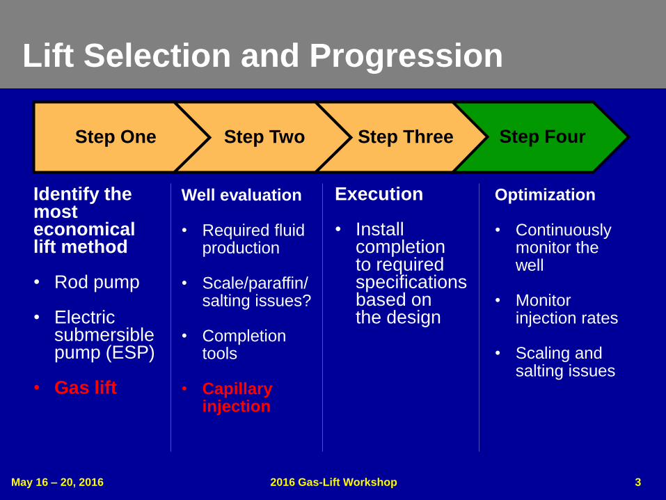
Lift Selection and Progression
Step One Step Two Step Three Step Four
Identify the most economical lift method
• Rod pump
• Electric submersible pump (ESP)
• Gas lift
Well evaluation
• Required fluid production
• Scale/paraffin/ salting issues?
• Completion tools
• Capillary injection
Execution
• Install completion to required specifications based onthe design
Optimization
• Continuously monitor the well
• Monitor injection rates
• Scaling and salting issues
May 16 – 20, 2016 2016 Gas-Lift Workshop 3

May 16 – 20, 2016 2016 Gas-Lift Workshop 4
Why Gas-Lift Solution?
• Identified gas lift as a successful lift type
– Successful between natural flow and reciprocating rod
lift due to high gas/oil ratio (GOR) and reservoir
pressure
– Can handle a wide range of production rates
– Continuous flow can handle sand
– Gas lift used with capillary injection for proper chemical
or fresh-water treatment
– Production packer critical in the completion

May 16 – 20, 20162016 Gas-Lift Workshop 5
Gas-Lift Inflow/Outflow
Multiple Nodal
Sensitivities must
be run to determine
performance over
the life of the well
• Required for
optimized valve
placement
• Ensures proper
transfer as the
well depletes

May 16 – 20, 2016 2016 Gas-Lift Workshop 6
Gas-Lift Design Considerations
• Designs to produce from 3,500 down to 200 B/D (556.5 to 31.8 m3/d) in 2.875- or 2.375-in. tubing
– 1-in. outside-diameter (OD), wireline-retrievable equipment for life-of-well scenario
• Enables design changes
• Ability to dummy upper valve stations to gain differential pressure later, if needed
• Tungsten-carbide seats for wet gas gravities (>0.75 SG)
– Conventional tubing-retrievable gas-lift equipment
• 1.5-in. OD valves in most cases
– Designed to operate through the reservoir decline
• 2.875- or 2.375-in. tubing will experience some instability at 300 to 200 B/D (31.8 to 47.7 m3/d)
– Convert to rod lift

May 16 – 20, 2016 2016 Gas-Lift Workshop 7
Design Verification with Dynalift™
Software

May 16 – 20, 2016 2016 Gas-Lift Workshop 8
Capillary
• Used for fresh-water injection to eliminate salt
buildup and bridges
– Multiple size cap strings up to 5/8 in., depending on
water volumes
• 120 to 125 B/D (19.1 to 19.9 m3/d) fresh water
– Run on outside of production tubing and terminate at
the injection mandrel
• Injection depth just above above production packer
• No lift-gas interference
• Not fighting high fluid levels
• Enables correct volumes of fresh water or chemical to be
delivered precisely at the required depth

• Typical wellbore
– 7-in. casing in vertical section
– 4.5-in. liner at kickoff point
• AS-1X production packer
– Wireline set with pump-out plug
• Enables well control when installing tubing
• Kill fluid not required
– Set in vertical section of the wellbore (7-in. casing)
• Minimizes mechanical risks
• Minimizes gas lift valve exposure to reservoir fluids
• Injection pressure not fighting reservoir pressures while
liftingMay 16 – 20, 2016 2016 Gas-Lift Workshop 9
Packer Completions
May 16 – 20, 2016 2016 Gas-Lift Workshop 10
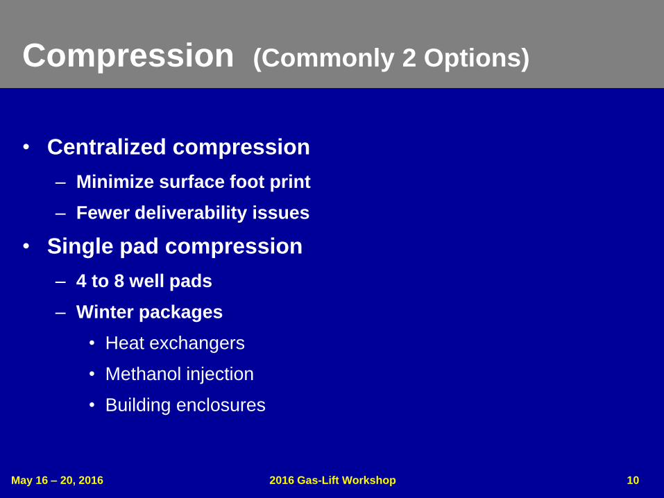
Compression (Commonly 2 Options)
• Centralized compression
– Minimize surface foot print
– Fewer deliverability issues
• Single pad compression
– 4 to 8 well pads
– Winter packages
• Heat exchangers
• Methanol injection
• Building enclosures

May 16 – 20, 2016 2016 Gas-Lift Workshop 11
Production and Optimization
• Optimization
– Higher water-cut reservoirs = higher gas-injection volumes
– Higher formation GORs = lower gas-injection volumes
• Monitor production rates and adjust injection accordingly
– Monitor plugging in tubulars from salt/scale/sand
• Ensure cap string is pumping fluid
– Compression
• Monitor freezing issues
• Monitor suction and discharge pressures
• Flowmeters and injection chokes – properly sized to minimize well surging
– Sand production flows to surface, where it is removed
May 16 – 20, 2016 2016 Gas-Lift Workshop 12
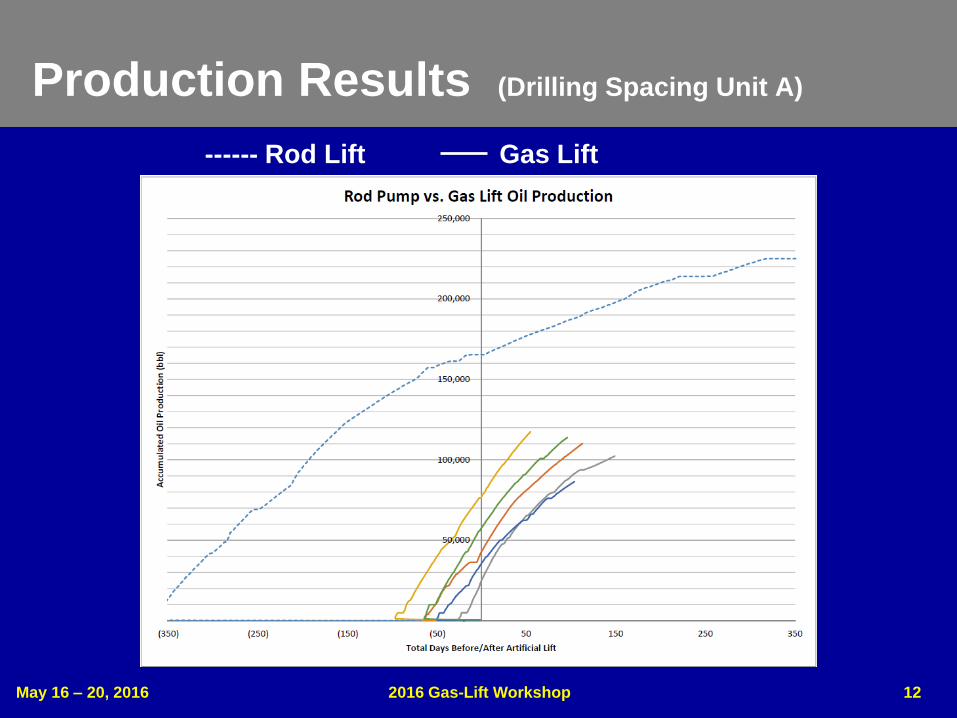
Production Results (Drilling Spacing Unit A)
------ Rod Lift Gas Lift

May 16 – 20, 2016 2016 Gas-Lift Workshop 13
Production Results (Drilling Spacing Unit B)
------ Rod Lift Gas Lift

May 16 – 20, 2016 2016 Gas-Lift Workshop 14
Production Results (Drilling Spacing Unit C)
------ Rod Lift Gas Lift
May 16 – 20, 2016 2016 Gas-Lift Workshop 15
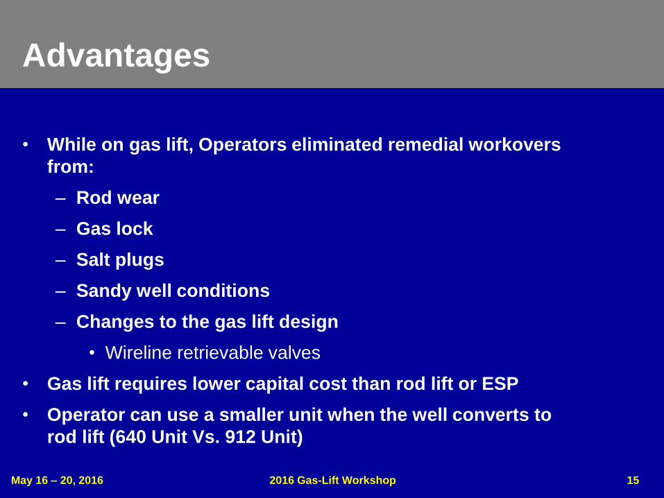
Advantages
• While on gas lift, Operators eliminated remedial workovers
from:
– Rod wear
– Gas lock
– Salt plugs
– Sandy well conditions
– Changes to the gas lift design
• Wireline retrievable valves
• Gas lift requires lower capital cost than rod lift or ESP
• Operator can use a smaller unit when the well converts to
rod lift (640 Unit Vs. 912 Unit)

May 16 – 20, 2016 2016 Gas-Lift Workshop 16
Summary
• Gas lift is a good application for many Bakken wells as they
begin to load during natural flow
• Gas lift will efficiently produce the well until it stabilizes at
liquid and gas rates suitable for rod lift
• Capillary strings can be effectively utilized to keep tubulars
clear and treat for corrosion
• Packers are a critical part of well efficiency and wellbore
protection

May 16 – 20, 2016 2016 Gas-Lift Workshop 17
Copyright
Rights to this presentation are owned by the company(ies) and/or author(s) listed on the title page. By submitting this presentation to the Gas-Lift Workshop, they grant to the Workshop, the Artificial Lift Research and Development Council (ALRDC), and the American Society of Mechanical Engineers (ASME), rights to:
– Display the presentation at the Workshop.
– Place it on the www.alrdc.com web site, with access to the site to be as directed by the Workshop Steering Committee.
– Place it on a CD for distribution and/or sale as directed by the Workshop Steering Committee.
Other uses of this presentation are prohibited without the expressed written permission of the company(ies) and/or author(s) who own it and the Workshop Steering Committee.

May 16 – 20, 2016 2016 Gas-Lift Workshop 18
Disclaimer
The following disclaimer shall be included as the last page of a Technical Presentation or Continuing Education Course. A similar disclaimer is included on the front page of the Gas-Lift Workshop Web Site.
The Artificial Lift Research and Development Council and its officers and trustees, and the Gas-Lift Workshop Steering Committee members, and their supporting organizations and companies (here-in-after referred to as the Sponsoring Organizations), and the author(s) of this Technical Presentation or Continuing Education Training Course and their company(ies), provide this presentation and/or training material at the Gas-Lift Workshop "as is" without any warranty of any kind, express or implied, as to the accuracy of the information or the products or services referred to by any presenter (in so far as such warranties may be excluded under any relevant law) and these members and their companies will not be liable for unlawful actions and any losses or damage that may result from use of any presentation as a consequence of any inaccuracies in, or any omission from, the information which therein may be contained.
The views, opinions, and conclusions expressed in these presentations and/or training materials are those of the author and not necessarily those of the Sponsoring Organizations. The author is solely responsible for the content of the materials.
The Sponsoring Organizations cannot and do not warrant the accuracy of these documents beyond the source documents, although we do make every attempt to work from authoritative sources. The Sponsoring Organizations provide these presentations and/or training materials as a service. The Sponsoring Organizations make no representations or warranties, express or implied, with respect to the presentations and/or training materials, or any part thereof, including any warrantees of title, non-infringement of copyright or patent rights of others, merchantability, or fitness or suitability for any purpose.