gas fuelled engine installations - dnv gl · 120 single gas fuel system is a power generating...
TRANSCRIPT

RULES FORCLASSIFICATION OF
DET NORSKE VERITAS
Veritasveien 1, N-1322 Høvik, Norway Tel.: +47 67 57 99 00 Fax: +47 67 57 99 11
SHIPS
NEWBUILDINGS
SPECIAL EQUIPMENT AND SYSTEMSADDITIONAL CLASS
PART 6 CHAPTER 13
GAS FUELLED ENGINE INSTALLATIONSJANUARY 2001
CONTENTS PAGE
Sec. 1 General Requirements ................................................................................................................ 5Sec. 2 Materials ..................................................................................................................................... 8Sec. 3 Arrangement and System Design ............................................................................................... 9Sec. 4 Fire Safety ................................................................................................................................ 13Sec. 5 Electrical Systems .................................................................................................................... 14Sec. 6 Control, Monitoring and Safety Systems ................................................................................. 15Sec. 7 Compressors and Gas Engines ................................................................................................. 20Sec. 8 Manufacture, Workmanship and Testing ................................................................................. 21

CHANGES IN THE RULES
Comments to the rules may be sent by e-mail to [email protected] subscription orders or information about subscription terms, please use [email protected] information about DNV and the Society's services is found at the Web site http://www.dnv.com
© Det Norske VeritasComputer Typesetting (FM+SGML) by Det Norske VeritasPrinted in Norway by GCS AS.
If any person suffers loss or damage which is proved to have been caused by any negligent act or omission of Det Norske Veritas, then Det Norske Veritas shall pay compensation to such personfor his proved direct loss or damage. However, the compensation shall not exceed an amount equal to ten times the fee charged for the service in question, provided that the maximum compen-sation shall never exceed USD 2 million.In this provision "Det Norske Veritas" shall mean the Foundation Det Norske Veritas as well as all its subsidiaries, directors, officers, employees, agents and any other acting on behalf of DetNorske Veritas.
General
The Board approved this new chapter in December 2000. The rulescome into force 1 July 2001.
This chapter is valid until superseded by a revised chapter. Supple-ments will not be issued except for an updated list of minor amend-ments and corrections, which will be presented in Pt.0 Ch.1 Sec.3.Pt.0 Ch.1 is normally revised in January and July each year.
Revised chapters will be forwarded to all subscribers to the rules.Buyers of reprints are advised to check the updated list of rule chap-ters printed in Pt.0 Ch.1 Sec.1 to ensure that the chapter is current.
Introduction
This new chapter on gas fuelled engine installations, in ships, otherthan gas carriers, has been introduced from January 2001. A new safe-ty concept in addition to the double pipe system has also been intro-duced, called "emergency shutdown protected machinery space". Theinformation formerly given in Classification Note 42.1 and Certifica-tion Note 2.11 has been included. The new chapter covers the entiregas installation including gas containment, piping arrangements andgas engine design, and both dual fuel and gas only engine installa-tions.

Rules for Ships, January 2001Pt.6 Ch.13 Contents – Page 3
DET NORSKE VERITAS
CONTENTS
SEC. 1 GENERAL REQUIREMENTS .......................... 5
A. Classification..........................................................................5A 100 Application........................................................................5A 200 Class notation....................................................................5A 300 Survey extent ....................................................................5
B. Definitions .............................................................................5B 100 Terms ................................................................................5
C. Documentation ......................................................................5C 100 Plans and particulars .........................................................5
D. Certification...........................................................................6D 100 Gas engines .......................................................................6D 200 Pressure vessels.................................................................6D 300 Valves ...............................................................................7D 400 Pumps and compressors ....................................................7
E. Operation and Maintenance Manuals.................................7E 100 Contents ............................................................................7
SEC. 2 MATERIALS........................................................ 8
A. General...................................................................................8A 100 Material requirements .......................................................8
SEC. 3 ARRANGEMENT AND SYSTEM DESIGN .... 9
A. Location and Separation of Spaces......................................9A 100 Gas compressor room........................................................9A 200 Engine rooms ....................................................................9A 300 Tank rooms .......................................................................9
B. Arrangement of Entrances and Other Openings ...............9B 100 General ..............................................................................9
C. General Gas Pipe Design ......................................................9C 100 General ..............................................................................9
D. System Configuration ...........................................................9D 100 General ..............................................................................9D 200 Inherently gas safe machinery spaces ...............................9D 300 ESD protected machinery spaces......................................9
E. Gas Supply System in Machinery Spaces .........................10E 100 Gas supply system for inherently gas safe machinery
spaces ..............................................................................10E 200 Gas supply system for ESD protected machinery
spaces ..............................................................................10
F. Gas Fuel Storage .................................................................10F 100 Liquefied gas storage tanks.............................................10F 200 Compressed gas storage tanks.........................................10F 300 Storage above deck .........................................................10F 400 Storage below deck .........................................................11
G. Fuel Bunkering System and Distribution System outsideMachinery Spaces ...............................................................11
G 100 Fuel bunkering station.....................................................11G 200 Bunkering system............................................................11G 300 Distribution outside of machinery spaces .......................11
H. Ventilation Systems............................................................11H 100 General ............................................................................11H 200 Gas tank room .................................................................11
H 300 Engine room....................................................................11H 400 Pump and compressor rooms ..........................................11
SEC. 4 FIRE SAFETY ................................................... 13
A. General ................................................................................ 13A 100 General ............................................................................13
B. Fire Protection.................................................................... 13B 100 Construction....................................................................13
C. Fire Extinction................................................................... 13C 100 Fire main .........................................................................13C 200 Water spray systems .......................................................13C 300 Dry chemical powder fire extinguishing system ............13
D. Fire Detection and Alarm Systems ................................... 13D 100 Detection .........................................................................13D 200 Alarms and safety actions ...............................................13
SEC. 5 ELECTRICAL SYSTEMS ............................... 14
A. General ................................................................................ 14A 100 General ............................................................................14
SEC. 6 CONTROL, MONITORING AND SAFETYSYSTEMS ........................................................... 15
A. General ................................................................................ 15A 100 Introduction.....................................................................15
B. Monitoring .......................................................................... 15B 100 Gas tank monitoring........................................................15B 200 Gas compressor monitoring ............................................15B 300 Gas engine monitoring....................................................15
C. Gas Detection...................................................................... 16C 100 Locations.........................................................................16
D. Safety Functions of Gas Supply Systems ......................... 16D 100 General ............................................................................16
SEC. 7 COMPRESSORS AND GAS ENGINES ......... 20
A. Gas Compressors................................................................ 20A 100 General ............................................................................20A 200 Vibrations........................................................................20
B. Gas Engine Design ............................................................. 20B 100 General ............................................................................20B 200 Functional requirements dual fuel engines .....................20B 300 Functional requirements gas-only engines......................20B 400 Design of on-engines piping on gas-only engines ..........20
SEC. 8 MANUFACTURE, WORKMANSHIP ANDTESTING ............................................................ 21
A. Gas Tanks ........................................................................... 21A 100 Manufacture and testing..................................................21
B. Gas Piping Systems ........................................................... 21B 100 Gas pipes.........................................................................21B 200 Ducting............................................................................21B 300 Valves .............................................................................21B 400 Expansion bellows ..........................................................21

Rules for Ships, January 2001Pt.6 Ch.13 Contents – Page 4
DET NORSKE VERITAS
Rules for Ships, January 2001Pt.6 Ch.13 Sec.1 – Page 5
DET NORSKE VERITAS
SECTION 1GENERAL REQUIREMENTS
A. Classification
A 100 Application101 The rules in this chapter apply to internal combustionengine installations in ships other than LNG carriers using gasas fuel. However, the requirements for machinery arrange-ments under the "inherently safe" concept can also be appliedto LNG carriers, while application of the ESD concept requiresacceptance by the Flag Administration under the equivalencyclause in the IGC Code. The engines may be either single fuelengines or dual fuel engines, and the gas may be in gaseous orliquid state.
Guidance note:The use of gas as fuel in ships other than LNG carriers is not cov-ered by international conventions and such installations will needadditional acceptance by flag authorities.
---e-n-d---of---G-u-i-d-a-n-c-e---n-o-t-e---
A 200 Class notation201 Ships built with machinery satisfying the requirementsin this chapter will be given class notation:
GAS FUELLED.
A 300 Survey extent301 Survey requirements for ships with the class notationGAS FUELLED are given in Pt.7 Ch.2 Sec.4 O.
B. Definitions
B 100 Terms101 Accommodation spaces: See Pt.4 Ch.10 Sec.1 C300.
102 Control stations: See Pt.4 Ch.10 Sec.1 C400.Guidance note:This does not include special fire control equipment that can bemost practically located in the cargo area (if the vessel is a cargoship).
---e-n-d---of---G-u-i-d-a-n-c-e---n-o-t-e---
103 Double block and bleed valve is a set of three automaticvalves located at the fuel supply to each of the gas engines.Two of these valves are to be in series in the gas fuel pipe tothe consuming equipment. The third valve is to be in a pipe thatvents to a safe location in the open air, that portion of the gasfuel piping that is between the two valves in series.
Alternatively, the function of one of the valves in series and theventilation valve can be incorporated into one valve body, soarranged that the flow to the gas utilisation unit will be blockedand the ventilation opened.
104 Dual fuel engines are in this context engines that canburn gaseous and liquid fuel simultaneously and in a wide va-riety of proportions.
105 ESD means emergency shutdown.
106 Enclosed spaces are spaces bounded by bulkheads anddecks that may have doors, windows or other similar openings.
107 Engine room is in this chapter used for machinery spacescontaining gas fuelled engines.
108 Gas is defined as a fluid having a vapour pressure ex-ceeding 2.8 bar absolute at a temperature of 37.8°C.
109 Gas dangerous spaces are:
— enclosed or semi-enclosed spaces containing gas sources— enclosed or semi-enclosed spaces having accesses or
openings into any other gas dangerous space.
Enclosed spaces having direct access or openings to gas dan-gerous zones are also normally regarded as gas dangerousspaces if they are not equipped with approved arrangements toensure that their atmosphere is at all times maintained in a safecondition.
110 Gas dangerous zones are zones on open deck or semi-enclosed spaces on open decks within:
— 3 m of the gas tank pressure relief valve exhaust outlets— 3 m of gas tank openings, gas pipe flanges, openings to gas
dangerous spaces containing gas sources— 3 m of ventilation exhaust openings from rooms where gas
compressors, pumps or similar equipment are present andof ventilation exhaust openings from pipe ducting and en-gine rooms
— 2.4 m of the outer surface of a gas containment systemwhere such surface is exposed to the weather.
111 Gas safe areas are spaces or zones not being gas danger-ous.
112 Gas sources are any valves or detachable pipe joints inthe fuel gas system. Also compressors and seals of pumps inthe fuel gas system are regarded as gas sources.
113 High-pressure piping is in this context piping with max-imum working pressure above 10 bar.
114 LEL is lower explosion limit.
115 Main tank valve is a remote operated valve on the gasoutlet from a gas storage tank, located as close to the tank out-let point as possible.
116 Master gas fuel valve is an automatic valve in the gassupply line to each engine located outside the engine room andas close to the gas heater (if fitted) as possible.
117 Passenger areas are those spaces that are provided forthe accommodation and use of passengers, excluding baggage,store, provision and mail rooms.
118 Semi-enclosed spaces are locations where natural condi-tions of ventilation are notably different from those on opendecks due to the presence of structures such as roofs, windbreakers and bulkheads and which are so arranged that disper-sion of gas may not occur.
119 Service spaces are spaces outside the cargo area used forgalleys, pantries containing cooking appliances, lockers, mailand specie rooms, store rooms, workshops other than thoseforming part of the machinery spaces and similar spaces andtrunks to such spaces.
120 Single gas fuel system is a power generating system con-sisting of gas-only engines, not able to switch over to fuel oilrunning.
C. Documentation
C 100 Plans and particulars
101 Arrangement plans are to be submitted for approval giv-ing location of:
— machinery and boiler spaces, accommodation, service andcontrol station spaces
Rules for Ships, January 2001Pt.6 Ch.13 Sec.1 – Page 6
DET NORSKE VERITAS
— gas tanks and gas containment systems— gas pump and compressor rooms— gas piping with shore connections— tank hatches, ventilation pipes and any other openings to
the gas tanks— ventilating pipes, doors and openings to gas pump rooms,
compressor rooms and other gas-dangerous spaces— entrances, air inlets and openings to accommodation, serv-
ice and control station spaces— gas dangerous spaces and zones.
102 Plans of the gas containment system with the followingparticulars are to be submitted for approval:
— drawing of gas tanks including information on non-de-structive testing of welds and strength and tightness testingof tanks
— drawings of support and staying of independent tanks— specification of materials in gas tanks and gas piping sys-
tems— specifications of welding procedures for gas tanks— specification of stress relieving procedures for independ-
ent tanks type C (thermal or mechanical)— specification of design loads and structural analysis of gas
tanks— a complete stress analysis is to be submitted for independ-
ent tanks type C— specification of cooling-down procedure for gas tanks— arrangement and specifications of secondary barriers— drawings and specifications of tank insulation— drawing of marking plate for independent tanks.
103 Plans of the following piping systems are to be submit-ted for approval:
— drawings and specifications of gas piping including venti-lation lines of safety relief valves or similar piping
— drawings and specifications of offsets, loops, bends andmechanical expansion joints, such as bellows, slip joints(only inside tank) or similar means in the gas piping
— drawings and specifications of flanges, valves and otherfittings in the gas piping system. For valves intended forpiping systems with a design temperature below minus55°C, documentation for leak test and functional test at de-sign temperature (type test) is required
— complete stress analysis of piping system when designtemperature is below minus 110°C
— documentation of type tests for expansion components inthe gas piping system
— specification of materials, welding, post-weld heat treat-ment and non-destructive testing of gas piping
— specification of pressure tests (structural and tightnesstests) of gas piping
— program for functional tests of all piping systems includ-ing valves, fittings and associated equipment for handlinggas (liquid or vapour)
— drawings and specifications of insulation for low temper-ature piping where such insulation is installed
— specification of electrical bonding of piping— specification of means for removal of liquid contents from
bunkering pipes prior to disconnecting the shore connec-tion, see E100
— cooling or heating water system in connection with gasfuel system, if fitted.
104 The following plans and particulars for the safety reliefvalves are to be submitted for approval:
— drawings and specifications for safety relief valves andpressure/vacuum relief valves and associated ventilationpiping
— calculation of required gas tank relief valve capacity, in-cluding back pressure
— specification of procedures for changing of set pressuresof cargo tank safety relief valves if such arrangements arecontemplated
— calculations for safety valves ventilation mast: location,height, details.
105 Plans of the following equipment and systems with par-ticulars are to be submitted:
— drawings showing location and construction of air lockswith alarm equipment, if fitted
— drawings of gastight bulkhead penetrations, if fitted— arrangements and specifications of mechanical ventilation
systems in spaces covering gas fuel system, giving capac-ity and location of fans and their motors. Drawings andmaterial specifications of rotating parts and casings forfans and portable ventilators
— drawings and specifications of protection of hull steel be-neath liquid piping where liquid leakage may be anticipat-ed, such as at shore connections and at pump seals
— arrangement and specifications of piping systems for gasfreeing and purging of gas tanks
— for fixed gas detection and alarm systems: specificationand location of detectors, alarm devices and call points,and cable routing layout drawing
— bilge and drainage arrangements in gas pump rooms, com-pressor rooms, tank rooms
— exhaust gas system.
106 Plans of the following equipment and systems regardingfire protection are to be submitted for approval:
— arrangement and specification of water spray system, in-cluding pipes, valves, nozzles and fittings
— arrangement of ventilation duct required for gas pipes leadthrough enclosed spaces
— arrangement of ventilation duct for storage tank fitted be-low deck, if applicable
— arrangement of fire detection system for storage tank andventilation trunk
— arrangement of fire insulation for storage tank and pipes,ventilation trunks for storage tank room
— arrangement and specification of dry chemical powder in-stallation.
Plans of electrical installations giving the following particularsare to be submitted for approval:
— drawing(s) showing location of all electrical equipment ingas dangerous area
— single line diagram for intrinsically safe circuits— list of explosion protected equipment with reference to
drawings together with certificates.
107 A failure mode and effect analysis (FMEA) examiningall possible faults affecting the combustion process in the gasengines is to be submitted for approval.
108 An operation manual is to be submitted for approval, toinclude information as outlined in E100.
D. Certification
D 100 Gas engines
101 Gas engines are in addition to the requirements in thischapter are to be certified in accordance with Pt.4 Ch.3.
D 200 Pressure vessels
201 Pressure vessels, which under normal operations willcontain gas in the liquid and/or gaseous state, are to be certifiedas class I pressure vessels in accordance with Pt.4 Ch.7.

Rules for Ships, January 2001Pt.6 Ch.13 Sec.1 – Page 7
DET NORSKE VERITAS
D 300 Valves301 For valves a DNV product certificate is required, as giv-en in Pt.4 Ch.7.
D 400 Pumps and compressors401 Pumps and compressors in gas systems are to be deliv-ered with a DNV product certificate.
402 For general requirements and in regard to testing ofpumps: See Pt.4 Ch.6.
403 For general requirements and with regard to testing ofcompressors: See Pt.4 Ch.5.
E. Operation and Maintenance Manuals
E 100 Contents101 An operation manual is to include:
— bunkering procedure— gas freeing and inerting procedures— normal operation procedures of the gas system
— emergency operation procedures of the gas system.
102 A plan for systematic maintenance and function testingis to be kept onboard showing in detail how components andsystems are to be tested and what is to be observed during thetests. Columns showing test dates and verification of tests car-ried out are to be included. The plan is to include:
— all instrumentation, automation and control systems af-fecting the gas supply system
— test intervals to reflect the consequences of failure involv-ing a particular system. Functional testing of criticalalarms should not exceed 3 months intervals. Normally thelongest intervals are not to surpass 12 months.
The plan should be included in the plan required for the classnotation E0.
Guidance note:Critical alarms are defined as low lubricating oil pressure alarmsfor rotating machinery.
---e-n-d---of---G-u-i-d-a-n-c-e---n-o-t-e---

Rules for Ships, January 2001Pt.6 Ch.13 Sec.2 – Page 8
DET NORSKE VERITAS
SECTION 2MATERIALS
A. General
A 100 Material requirements101 Materials are in general to be in accordance with the re-quirements in Pt.2.
102 Materials used in gas tanks, gas piping, process pressurevessels and other components in contact with gas are to be in
accordance with Pt.5 Ch.5 Sec.2 D. For piping see Pt.5 Ch.5Sec.6 C200.
103 The materials used in gas piping systems are to be fur-nished with documentation in accordance with Pt.5 Ch.5 Sec.2Table E1. For the definition of material documentation see Pt.1Ch.1 Sec.3.

Rules for Ships, January 2001Pt.6 Ch.13 Sec.3 – Page 9
DET NORSKE VERITAS
SECTION 3ARRANGEMENT AND SYSTEM DESIGN
A. Location and Separation of Spaces
A 100 Gas compressor room
101 Compressor rooms, if arranged, are to be located aboveweather deck level, unless especially approved by DNV.
102 Electric drive motors are to be located in an adjacent gassafe space. The bulkhead penetration is to be of gas tight type.
A 200 Engine rooms
201 When more than one engine room is required and theserooms are separated by a single bulkhead, the bulkhead is tohave sufficient strength to withstand a local gas explosion. Astrength standard of the bulkhead corresponding to that of awatertight bulkhead is considered adequate.
202 Engine rooms are to have as simple geometrical shapeas possible.
A 300 Tank rooms
301 Tank rooms boundaries are to be gas tight.
302 The tank room is not to be located adjacent to machin-ery spaces of category A. If the separation is by means of a cof-ferdam then additional insulation to class A-60 standard is tobe fitted.
B. Arrangement of Entrances and Other Open-ings
B 100 General
101 If the compressor room is approved located below deckthe room is to have a separate access from deck, not sharedwith any other spaces.
102 The tank room entrance is to be arranged with a sillheight of at least 300 mm.
103 Access to the tank room is to be through a separate ac-cess from the deck, not shared with any other spaces. The ac-cess trunk is to be fitted with separate ventilation.
104 An engine room containing gas engines is to have atleast two completely independent exits. However, if the engineroom is very small, this requirement can be waived after spe-cial consideration by DNV.
105 If the access to the engine room is from another enclosedspace in the ship, the entrances are to be arranged with self-closing doors. An alarm is to sound if the door is open contin-uously for more than 1 minute. As an alternative an arrange-ment with two self-closing doors in series can be approved.
C. General Gas Pipe Design
C 100 General
101 Gas pipes are in general to comply with the applicableparts of Pt.5 Ch.5 Sec.6.
102 Gas pipes are not to be located less than 760 mm fromthe ship's side.
103 An arrangement for purging gas bunkering lines andsupply lines (only up to the double block and bleed valves ifthese are located close to the engine) with nitrogen is to be pro-vided.
104 The gas piping system is to be installed with sufficientflexibility. Bellows will not be accepted in enclosed spaces.
105 A system for colour marking of all gas pipes should beused, e.g. yellow painted pipes.
106 If the fuel gas contains heavier components that maycondense in the system, knock out drums or equivalent meansfor collecting the liquid are to be fitted.
D. System Configuration
D 100 General101 Two alternative system configurations may be accepted:
I Inherently gas safe machinery spaces: Arrangements in ma-chinery spaces are such that the spaces are considered gas safeunder all conditions, normal as well as abnormal conditions i.e.inherently gas safe.
II ESD protected machinery spaces: Arrangements in machin-ery spaces are such that the spaces are considered gas safe un-der normal conditions, but under certain abnormal conditionsmay have the potential to become gas dangerous. In the eventof abnormal conditions involving gas hazards, emergencyshutdown (ESD) of non-safe equipment (ignition sources) andmachinery is to be automatically executed while equipment ormachinery in use or active during these conditions are to be ofexplosion protected design.
D 200 Inherently gas safe machinery spaces
201 All gas supply piping within machinery space bounda-ries must be enclosed in a gas tight enclosure, i.e. double wallpiping or ducting.
202 In case of leakage in a gas supply pipe making shutdownof the gas supply necessary, a secondary independent fuel sup-ply must be available. Alternatively, in the case of multi-en-gine installations, independent and separate gas supplysystems for each engine or group of engines may be accepted.
203 For single fuel installations (gas only) the fuel storageis to be divided between two or more tanks of approximatelyequal size. The tanks shall be located in separate compart-ments.
D 300 ESD protected machinery spaces
301 Gas supply piping within machinery spaces may be ac-cepted without a gas tight external enclosure on the followingconditions:
a) Engines for generating propulsion power and electricpower are to be located in two or more engine rooms nothaving any common boundaries unless it can be docu-mented that the common boundary can withstand an ex-plosion in one of the rooms. Distribution of enginesbetween the different engine rooms is to be such that in thecase of shutdown of fuel supply to any one engine room itmust be possible to maintain at least 40% of the propulsionpower plus normal electrical power supply for sea goingservices. Incinerators, inert gas generators or other oilfired boilers are not to be located within an ESD protectedmachinery space.
b) Pressure in gas supply lines within machinery spaces to beless than 10 bar.
c) A gas detection system arranged to automatically shut-down the gas supply (also oil fuel supply if dual fuel) and

Rules for Ships, January 2001Pt.6 Ch.13 Sec.3 – Page 10
DET NORSKE VERITAS
disconnect all non-explosion protected equipment or in-stallations is to be fitted.
302 For single fuel installations (gas only) the fuel storageis to be divided between two or more tanks of approximatelyequal size. The tanks shall be located in separate compart-ments.
E. Gas Supply System in Machinery Spaces
E 100 Gas supply system for inherently gas safemachinery spaces101 Gas supply lines passing through enclosed spaces are tobe completely enclosed by a double pipe or duct. This doublepipe or duct is to fulfil one of the following:
a) The gas piping is to be a double wall piping system withthe gas fuel contained in the inner pipe. The space betweenthe concentric pipes is to be pressurised with inert gas at apressure greater than the gas fuel pressure. Suitable alarmsare to be provided to indicate a loss of inert gas pressurebetween the pipes.
b) The gas fuel piping is to be installed within a ventilatedpipe or duct. The air space between the gas fuel piping andthe wall of the outer pipe or duct is to be equipped withmechanical underpressure ventilation having a capacity ofat least 30 air changes per hour. This ventilation capacitycan be reduced to 10 air changes per hour provided auto-matic filling of the duct with nitrogen upon detection ofgas is arranged for. The fan motors are to be placed outsidethe ventilated pipe or duct. The ventilation outlet is to becovered by a protection screen and placed in a positionwhere no flammable gas-air mixture may be ignited.
102 The connecting of gas piping and ducting to the gas in-jection valves must be so as to provide complete coverage bythe ducting. The arrangement must facilitate replacement andor overhaul of injection valves and cylinder covers.
103 For high-pressure piping the design pressure of theducting is to be taken as the higher of the following:
— the maximum built up pressure: static pressure in way ofthe rupture resulting from the gas flowing in the annularspace
— local instantaneous peak pressure in way of the rupture*:this pressure is to be taken as the critical pressure and isgiven by the following expression:
p0 = maximum working pressure of the inner pipek = Cp/Cv constant pressure specific heat divided by
the specific volume specific heatk = 1.31 for CH4
The tangential membrane stress of a straight pipe is not to ex-ceed the tensile strength divided by 1.5 (Rm/1.5) when subject-ed to the above pressure. The pressure ratings of all otherpiping components are to reflect the same level of strength asstraight pipes.
As an alternative to using the peak pressure from the above for-mula, the peak pressure found from representative tests can beused. Test reports must then be submitted.
104 For low pressure piping the duct is to be dimensionedfor a design pressure not less than that of the gas pipes. Theduct is also to be pressure tested to show that it can withstandthe expected maximum pressure at gas pipe rupture.
105 The arrangement and installation of the high-pressure
gas piping must provide the necessary flexibility for the gassupply piping to accommodate the oscillating movements ofthe main engine, without running the risk of fatigue problems.The length and configuration of the branch lines are importantfactors in this regard.
E 200 Gas supply system for ESD protected machineryspaces201 The pressure in the gas supply system shall not exceed10 bar.
202 The gas supply lines are to have a design pressure notless than 10 bar.
F. Gas Fuel Storage
F 100 Liquefied gas storage tanks101 The storage tank used for liquefied gas is to be an inde-pendent tank type C designed in accordance with Pt.5 Ch.5Sec.5, in particular Sec.5 I.
102 Pipe connections to the tank are to be in accordance withPt.5 Ch.5 Sec.6 C303 to C307. However, connections belowthe lowest liquid level may be accepted after special consider-ation by DNV.
103 Pressure relief valves as required in Pt.5 Ch.5 Sec.9B200 are to be fitted.
104 The outlet from the pressure relief valves are normallyto be located at least B/3 or 6 m, whichever is greater, abovethe weather deck and 6 m above the working area and gang-ways, where B is the greatest moulded breadth of the ship inmetres. The outlets are to be located at least 10 m from thenearest:
— air intake, air outlet or opening to accommodation, serviceand control spaces, or other gas safe spaces
— exhaust outlet from machinery or from furnace installa-tion.
105 Storage tanks for liquid gas with vapour pressure abovethe design pressure at 45°C are to be fitted with efficient insu-lation.
106 Storage tanks for liquid gas shall not be filled to morethan 98% full at the reference temperature, where the referencetemperature is as defined in Pt.5 Ch.5 Sec.17 A105. A fillinglimit curve for actual filling temperatures is to be preparedfrom the formula given in Pt.5 Ch.5 Sec.17 A102. However,when the tank insulation and tank location makes the probabil-ity very small for the tank contents to be heated up due to ex-ternal fire, special considerations can be made to allow ahigher filling limit than calculated using the reference temper-ature, but never above 95%.
F 200 Compressed gas storage tanks201 The storage tanks to be used for compressed gas are tobe in accordance with Pt.4 Ch.7 and are to be certified byDNV.
202 Tanks for compressed gas are to be fitted with pressurerelief valves with a set point below the design pressure of thetank and with outlet located as required in C104.
F 300 Storage above deck301 Both gases of the compressed and the liquefied type willbe accepted stored above deck level.
302 The storage tanks or tank batteries are to be located atleast B/5 from the ship's side.
303 The gas storage tanks or tank batteries and equipmentare to be located to assure sufficient natural ventilation, so asto prevent accumulation of escaped gas.
p∗ p02
k 1+------------� �� �
kk 1+------------
=

Rules for Ships, January 2001Pt.6 Ch.13 Sec.3 – Page 11
DET NORSKE VERITAS
304 Tanks for liquid gas with a connection below the high-est liquid level, see 102, are to be fitted with drip trays belowthe tank and be of sufficient size to hold the full content of thetank. The material of the drip tray should be stainless steel, andthere should be efficient separation or isolation so that the hullor deck structures are not exposed to unacceptable cooling, incase of leakage of liquid gas.
F 400 Storage below deck
401 Only gas in a liquid state can be stored below deck level.
402 The maximum acceptable working pressure of a storagetank located below deck level is 10 bar.
403 The storage tank is to be located:
— minimum, the lesser of B/5 and 11.5 m from the ship side— minimum, the lesser of B/15 and 2 m from the bottom plat-
ing— not less than 760 mm from the shell plating.
404 The storage tank and associated valves and piping are tobe located in a space designed to act as a secondary barrier, incase of liquid gas leakage. This implies that the material is tobe in accordance with Pt.5 Ch.5 Sec.2 D, for secondary barri-ers, and that the space is to be designed to withstand the max-imum pressure build up. Alternatively, pressure relief ventingto a safe location (mast) can be provided. The space is to be ca-pable of containing leakage, and is to be isolated thermally sothat the surrounding hull is not exposed to unacceptable cool-ing, in case of leakage of the liquid gas. This secondary barrierspace is in other parts of this chapter called "tank room".
405 Bilge suctions from the tank room, if provided, are notto be connected to the bilge system for the rest of the ship.
G. Fuel Bunkering System and Distribution Sys-tem outside Machinery Spaces
G 100 Fuel bunkering station
101 The bunkering station is to be so located that sufficientnatural ventilation is provided. Closed or semi-enclosed bun-kering stations will be subject to special consideration.
102 Drip trays are to be fitted below the bunkering connec-tions and where leakage may occur. The drip trays are to bemade of stainless steel, and should be drained over the ship'sside by a pipe that preferably leads down into the sea. This pipecould be temporarily fitted for bunkering operations. The sur-rounding hull or deck structures are not to be exposed to unac-ceptable cooling, in case of leakage of liquid gas.
103 Control of the bunkering is to be possible from a safe lo-cation in regard to bunkering operations. At this location tankpressure and tank level is to be monitored. Overfill alarm andautomatic shutdown are also to be indicated at this location.
G 200 Bunkering system
201 The bunkering system is to be so arranged that no gas isdischarged to air during filling of storage tanks.
202 A manually operated stop valve and a remote operatedshutdown valve in series, or a combined manually operatedand remote valve are to be fitted in every bunkering line closeto the shore connecting point. It is to be possible to release theremote operated valve in the control location for bunkering op-erations and or another safe location.
203 If the ventilation in the ducting around the gas bunker-ing lines stop, an alarm is to sound at the bunkering control lo-cation.
204 If gas is detected in the ducting around the bunkeringlines an alarm is to sound at the bunkering control location.
205 Means are to be provided for draining the liquid fromthe bunkering pipes at bunkering completion.
206 Bunkering lines are to be arranged for inerting and gasfreeing. During operation of the vessel the bunkering pipes areto be gas free.
G 300 Distribution outside of machinery spaces
301 Gas fuel piping is not to be lead through accommoda-tion spaces, service spaces or control stations.
302 Where gas pipes pass through enclosed spaces in theship, they are to be enclosed in a duct. This duct is to be me-chanically underpressure ventilated with 30 air changes perhour, and gas detection as required in Sec.6 is to be provided.
303 The duct is to be dimensioned according to E103 toE105.
304 Gas pipes located in open air are to be so located thatthey are not likely to be damaged by accidental mechanical im-pact.
305 High-pressure gas lines outside the engine room spacesshould be installed and protected so as to minimise the risk ofinjury to personnel in case of rupture.
H. Ventilation Systems
H 100 General
101 The ventilation systems serving spaces containing gassources shall be independent from other ventilation systems inthe ship. Electric fan motors are not to be located within theventilation ducts.
102 For design of ventilation fans serving spaces containinggas sources see requirements in Pt.5 Ch.5 Sec.10 A100.
103 Means should be provided to indicate in the engine con-trol station any loss of the required ventilating capacity.
104 Ventilation inlets for spaces containing gas sources areto be located outside gas dangerous zones at places where thereis the least possible risk of gas, gas-air mixtures or sparks beingdrawn into the system.
H 200 Gas tank room
201 The tank room for gas storage tank located below deckis to be provided with an effective mechanical ventilation sys-tem of the underpressure type, providing a ventilation capacityof at least 30 air changes per hour.
202 Approved automatic fail-safe fire dampers are to be fit-ted in the ventilation trunk for tank room.
H 300 Engine room
301 The ventilation system for the engine room is to be in-dependent of all other ventilation.
302 ESD protected engine rooms are to have ventilation witha capacity of at least 30 air changes per hour. The ventilationsystem is to ensure a good air circulation in all spaces, and inparticular ensure that there is no possibility of formation of gaspockets in the room.
303 The number and power of the ventilation fans are to besuch that the capacity is not reduced by more than 50%, if a fanwith a separate circuit from the main switchboard or emergen-cy switchboard or a group of fans with common circuit fromthe main switchboard or emergency switchboard, is out of ac-tion.
H 400 Pump and compressor rooms
401 Pump and compressor rooms are to be fitted with effec-tive mechanical ventilation system of the underpressure type,

Rules for Ships, January 2001Pt.6 Ch.13 Sec.3 – Page 12
DET NORSKE VERITAS
providing a ventilation capacity of at least 30 air changes perhour.
402 Ventilation systems for pump and compressor rooms areto be in operation when pumps or compressors are working.Pumps and compressors are not to be started before the venti-lation system in the electric motor room has been in operationfor 15 minutes. Warning notices to this effect are to be placedin an easily visible position near the control stand.
Rules for Ships, January 2001Pt.6 Ch.13 Sec.4 – Page 13
DET NORSKE VERITAS
SECTION 4FIRE SAFETY
A. General
A 100 General101 The requirements in this chapter are additional to thosegiven in Pt.4 Ch.10.
102 For the purpose of fire protection gas compressor roomsare to be treated as cargo compressor rooms in accordance withPt.5 Ch.5 Sec.11.
B. Fire Protection
B 100 Construction101 Tanks or tank batteries located above deck are to beshielded with class A-60 insulation towards accommodation,service stations, cargo spaces and machinery spaces.
102 The tank room and ventilation trunks to such spaces be-low the bulkhead deck are to be fire insulated to class A-60standard. However, where the room is adjacent to tanks, voids,auxiliary machinery spaces of no fire risk, sanitary and similarspaces, the insulation may be reduced to class A-0.
103 Gas pipes lead through ro-ro spaces on open deck will besubject to special considerations by DNV and might need classA-60 fire insulation.
104 The bunkering station is to be shielded with class A-60insulation towards other spaces, except for spaces such astanks, voids, auxiliary machinery spaces of no fire risk, sani-tary and similar spaces where the insulation may be reduced toA-0 class.
105 When more than one engine room is required and theserooms are separated by a single bulkhead, the bulkhead is to befire insulated to class A-60 standard.
C. Fire Extinction
C 100 Fire main101 The water spray system required below may be part ofthe fire main system provided that the required fire pump ca-pacity and pressure is sufficient to operation of both the re-quired numbers of hydrants and hoses and the water spraysystem simultaneously.
102 When the storage tank is located above the bulkheaddeck, isolating valves are to be fitted in the fire main in orderto isolate damage sections of the main.
C 200 Water spray systems201 A water spray system is to be fitted for cooling and fireprevention and to cover exposed parts of storage tank locatedabove deck.
202 The system is to be designed to cover all areas as speci-fied above with an application rate of 10 l/min/m2 for horizon-tal projected surfaces and 4 l/min/m2 for vertical surfaces.
203 For the purpose of isolating damage sections, stopvalves are to be fitted or the system may be divided into twosections with control valves located in a safe and readily acces-sible position not likely to be cut-off in case of fire.
204 The capacity of the water spray pump is to be sufficientto deliver the required amount of water to the hydraulicallymost demanding area as specified above.
205 A connection to the ships fire main through a stop valveis to be provided.
206 Remote start of pumps supplying the water spray systemand remote operation of any normally closed valves to the sys-tem should be located in a readily accessible position which isnot likely to be cut off in case of fire in the areas protected.
207 The nozzles to be of an approved full bore type and theyare to be arranged to ensure an effective distribution of waterthroughout the space being protected.
C 300 Dry chemical powder fire extinguishing system301 In the bunkering station area a permanently installed drychemical powder extinguishing system is to cover all possibleleak points. The capacity is to be at least 50 kg with a rate ofdischarge of not less than 1 kg/s. The system is to be arrangedfor easy manual release from a safe location.
302 One portable dry powder extinguisher is to be locatednear the bunkering station.
303 Main engine rooms where the gas fuel is heavier than airare to be provided with at least one dry powder extinguisher lo-cated at the entrance to the room.
D. Fire Detection and Alarm Systems
D 100 Detection101 An approved fixed fire detection system is to be provid-ed for the tank room and the ventilation trunk for tank room be-low deck.
102 Smoke detectors alone are not considered sufficient forrapid fire detection.
103 Where the fire detection system does not include meansof remotely identifying each detector individually, the detec-tors are to be arranged on separate loops.
D 200 Alarms and safety actions201 Required safety actions at fire detection in the engineroom and tank room are given in Sec.6 Table D1. In additionthe ventilation is to stop automatically and fire dampers are toclose.

Rules for Ships, January 2001Pt.6 Ch.13 Sec.5 – Page 14
DET NORSKE VERITAS
SECTION 5ELECTRICAL SYSTEMS
A. General
A 100 General
101 The requirements in this chapter are additional to thosegiven in Pt.4 Ch.8.
102 Electrical equipment fitted within gas dangerous zoneson the open deck is to be in accordance with Pt.5 Ch.5 Sec.12B700.
103 The bunkering station is to be regarded as a gas danger-ous area, and any electrical equipment is to be in accordancewith Pt.5 Ch.5 Sec.12 B700. If the bunkering station is defi-cient of natural boundaries in all directions, then the zone is de-fined as 3 m from any gas pipe flange connections.
104 Tank rooms and compressor rooms are to be free fromignition sources of any type. Electrical equipment is to be of in-trinsically safe type. Lighting is to be certified safe-type of
pressurised and flameproof type, arranged in accordance withPt.4 Ch.8 Sec.9 D100. Gas detectors of the certified safe typeare accepted.
105 Any electrical equipment inside the gas piping duct is tobe of intrinsically safe type, except gas detectors, where certi-fied safe type are accepted.
106 Electrical equipment fitted in an ESD protected machin-ery space is to fulfil the following:
— In addition to fire and hydrocarbon detectors and fire andgas alarms, lighting and ventilation fans are to be certifiedsafe for a hydrocarbon gas atmosphere (ex(e) lighting andex(d) or ex(e) ventilation fans).
— all electrical equipment in the engine room of not certifiedsafe type for a hydrocarbon gas atmosphere are to be auto-matically disconnected if gas concentrations above 20%LEL is detected on two detectors in the engine room.

Rules for Ships, January 2001Pt.6 Ch.13 Sec.6 – Page 15
DET NORSKE VERITAS
SECTION 6CONTROL, MONITORING AND SAFETY SYSTEMS
A. General
A 100 Introduction101 For instrumentation and automation, including compu-ter based control and monitoring, the requirements in thischapter are additional to those given in Pt.4 Ch.9.
102 A local reading pressure gauge is to be fitted betweenthe stop valve and the connection to shore at each bunker pipe.
103 Pressure gauges are to be fitted to gas pump dischargelines and to the bunkering lines.
104 A bilge well in each tank room surrounding an inde-pendent cargo tank is to be provided with both a level indicatorand a temperature sensor. Alarm is to be given at high level inbilge well. Temperature sensor low temperature indication isto lead to automatic closing of main tank valve.
B. Monitoring
B 100 Gas tank monitoring101 Gas tanks are to be monitored and protected againstoverfilling as required in Pt.5 Ch.5 Sec.13 B100 and B200.
102 The temperature of the gas tank is to be monitored by aremote reading instrument.
103 Each tank is to be monitored with at least one local in-dicating instrument for pressure and remote pressure indica-tion at the control position. The manometers and indicators areto be clearly marked with the highest and lowest pressure per-mitted in the tank. In addition, high-pressure alarm, and if vac-uum protection is required, low pressure alarm is to beprovided on the bridge. The alarms are to be activated beforethe set pressures of the safety valves are reached.
B 200 Gas compressor monitoring201 The monitoring system shall include items given in Ta-ble B1.
B 300 Gas engine monitoring301 In addition to the requirements given in Pt.4 Ch.3 Sec.1E, monitoring as given in Table B2 is required for gas turbines.Additionally a failure mode and effect analysis (FMEA) exam-ining all possible faults affecting the combustion process shallbe submitted. Based on the outcome of the analysis deviationsin monitoring details compared to Table B2 may be acceptedor required.
Table B1 Monitoring system requirementsAlarm Automatic
stopGas heater outlet, temperature, high XGas compressor outlet, temperature, high X XGas compressor inlet, pressure, low XGas compressor outlet, pressure, high XGas compressor outlet, pressure, low XControl system failure XSealing gas pressure, low XLubrication oil pressure, low X XLubrication oil temperature, high XMaster gas valve close XIn addition high-pressure gas compressors are to stop automatically in theevent of:
— control air pressure loss— high gas concentration in the compressor room (Table D1)— automatic stop or emergency stop of gas supply to diesel engine.
Table B2 Monitoring of dual fuel diesel or gas-only enginesItem Alarm and safety action
(stated by an x)Alarm Automatic start of
standby pumpwith alarm 1)
Comments
Exhaust gas, outlet each cylinder Temperature, high x Automatic stop of gas supplyTemperature devia-tion from average,large
x Automatic stop of gas supply
Ignition failure each cylinder 2) x Automatic stop of gas supplyGas injection valve sealing oil pressure, low x High-pressure injection only
Lubricating oil inlet toengine 3)
Temperature, high xPressure, low x Independent of safety systemPressure, low xPressure, low x Engine shutdownFilter differentialpressure, high x
Cylinder lubrication 4) Flow, low x
Cylinder cooling medium
Pressure, low x
Pressure, low,temperature, high x x
Not required if main pump is engine drivenOutlet each cylinder if individual stop valves are fit-ted for the cylinder jackets
Rules for Ships, January 2001Pt.6 Ch.13 Sec.6 – Page 16
DET NORSKE VERITAS
C. Gas Detection
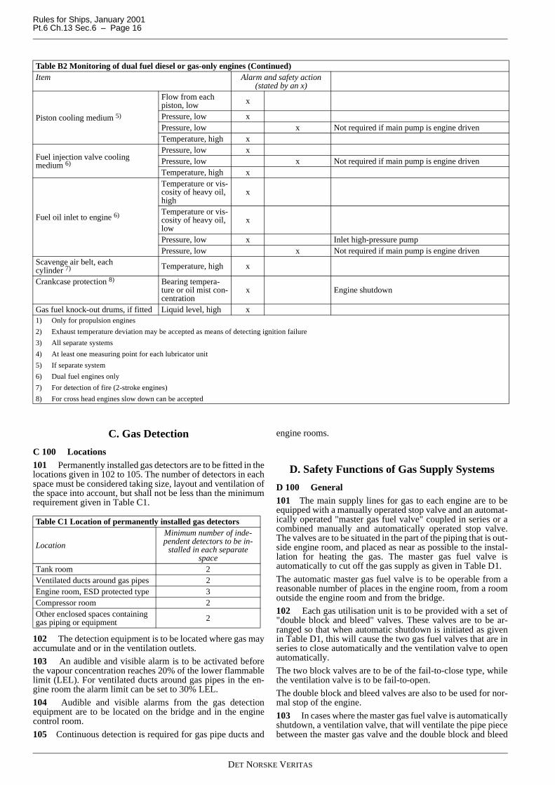
C 100 Locations101 Permanently installed gas detectors are to be fitted in thelocations given in 102 to 105. The number of detectors in eachspace must be considered taking size, layout and ventilation ofthe space into account, but shall not be less than the minimumrequirement given in Table C1.
102 The detection equipment is to be located where gas mayaccumulate and or in the ventilation outlets.
103 An audible and visible alarm is to be activated beforethe vapour concentration reaches 20% of the lower flammablelimit (LEL). For ventilated ducts around gas pipes in the en-gine room the alarm limit can be set to 30% LEL.
104 Audible and visible alarms from the gas detectionequipment are to be located on the bridge and in the enginecontrol room.
105 Continuous detection is required for gas pipe ducts and
engine rooms.
D. Safety Functions of Gas Supply Systems
D 100 General101 The main supply lines for gas to each engine are to beequipped with a manually operated stop valve and an automat-ically operated "master gas fuel valve" coupled in series or acombined manually and automatically operated stop valve.The valves are to be situated in the part of the piping that is out-side engine room, and placed as near as possible to the instal-lation for heating the gas. The master gas fuel valve isautomatically to cut off the gas supply as given in Table D1.
The automatic master gas fuel valve is to be operable from areasonable number of places in the engine room, from a roomoutside the engine room and from the bridge.
102 Each gas utilisation unit is to be provided with a set of"double block and bleed" valves. These valves are to be ar-ranged so that when automatic shutdown is initiated as givenin Table D1, this will cause the two gas fuel valves that are inseries to close automatically and the ventilation valve to openautomatically.
The two block valves are to be of the fail-to-close type, whilethe ventilation valve is to be fail-to-open.
The double block and bleed valves are also to be used for nor-mal stop of the engine.
103 In cases where the master gas fuel valve is automaticallyshutdown, a ventilation valve, that will ventilate the pipe piecebetween the master gas valve and the double block and bleed
Piston cooling medium 5)
Flow from eachpiston, low x
Pressure, low xPressure, low x Not required if main pump is engine drivenTemperature, high x
Fuel injection valve coolingmedium 6)
Pressure, low xPressure, low x Not required if main pump is engine drivenTemperature, high x
Fuel oil inlet to engine 6)
Temperature or vis-cosity of heavy oil,high
x
Temperature or vis-cosity of heavy oil,low
x
Pressure, low x Inlet high-pressure pumpPressure, low x Not required if main pump is engine driven
Scavenge air belt, eachcylinder 7) Temperature, high x
Crankcase protection 8) Bearing tempera-ture or oil mist con-centration
x Engine shutdown
Gas fuel knock-out drums, if fitted Liquid level, high x1) Only for propulsion engines
2) Exhaust temperature deviation may be accepted as means of detecting ignition failure
3) All separate systems
4) At least one measuring point for each lubricator unit
5) If separate system
6) Dual fuel engines only
7) For detection of fire (2-stroke engines)
8) For cross head engines slow down can be accepted
Table B2 Monitoring of dual fuel diesel or gas-only engines (Continued)Item Alarm and safety action
(stated by an x)
Table C1 Location of permanently installed gas detectors
Location
Minimum number of inde-pendent detectors to be in-
stalled in each separatespace
Tank room 2Ventilated ducts around gas pipes 2Engine room, ESD protected type 3Compressor room 2Other enclosed spaces containinggas piping or equipment 2

Rules for Ships, January 2001Pt.6 Ch.13 Sec.6 – Page 17
DET NORSKE VERITAS
valve, is to open. For high-pressure systems the pipe pieces be-tween the double block and bleed valve and the gas injectionvalves, are to be automatically vented. See Fig.1 and Fig.2. For
high-pressure systems the ventilation valves are to open at nor-mal stop of engine.
Fig. 1Alternative supply valve arrangements for high-pressure installations (single engine or separate master valve arrangement)

Rules for Ships, January 2001Pt.6 Ch.13 Sec.6 – Page 18
DET NORSKE VERITAS
Fig. 2Alternative supply valve arrangements for high-pressure installations (multi engine installation)
104 There is to be one manually operated shutdown valve inthe gas supply line to each engine to assure safe isolation dur-ing maintenance on the engine.
105 For one-engine installations and multi-engine installa-tions where a separate master valve is provided for each branchthe master gas fuel valve and the double block and bleed valvefunctions can be combined as shown in Fig.1 and Fig.2, for
high-pressure installations.
106 In the main supply gas line to each engine an automaticexcess flow shut off valve shall be fitted. The valve shall be ad-justed to shut off gas supply in the event of rupture of the gasline. The valve shall be located as close as possible to the pointof entry of the gas supply line into the engine room.

Rules for Ships, January 2001Pt.6 Ch.13 Sec.6 – Page 19
DET NORSKE VERITAS
Guidance note:The shutdown should be time delayed to prevent shutdown dueto transient load variations.
---e-n-d---of---G-u-i-d-a-n-c-e---n-o-t-e---
107 Full stop of ventilation in an engine room for a singlefuelled gas system shall, additionally to what is given in TableD1, lead to one of the following actions:
a) For a gas electric propulsion system with more than oneengine room: Another engine is to start. When the secondengine is connected to bus-bar the first engine is to be shut-down automatically.
b) For a direct propulsion system with more than one engineroom: The engine in the room with defect ventilation is tobe manually shutdown if at least 40% propulsion power isstill available after such a shutdown.
If only one engine room is fitted and ventilation in one of theenclosed ducts around the gas pipes is lost the master gas fuel
and double block and bleed valves in that supply line are toclose automatically provided the other gas supply unit is readyto deliver.
108 If the gas supply is shut off due to activation of an auto-matic valve, the gas supply is not to be opened until the reasonfor the disconnection is ascertained and the necessary precau-tions taken. A readily visible notice giving instruction to thiseffect is to be placed at the operating station for the shut-offvalves in the gas supply lines.
109 If a gas leak leading to a gas supply shutdown occurs,the gas fuel supply is not to be operated until the leak has beenfound and dealt with. Instructions to this effect are to be placedin a prominent position in the machinery space.
110 A signboard shall be permanently fitted in the engineroom stating that heavy lifting, implying danger of damage tothe gas pipes, is not to be done when the engine(s) is runningon gas.
Table D1 Monitoring of gas supply system to enginesParameter Alarm Automatic shut-
down of maintank valve
Automatic shut-down of gassupply to en-gine room 1)
Comment
Gas detection in tank room above 20% LEL XGas detection on second detector in tank roomabove 20% LEL X X
Fire detection in tank room X XBilge well high level tank room XBilge well low temperature in tank room X XGas detection in duct between tank and engineroom above 20% LEL X
Gas detection on second detector in duct be-tween tank and engine room above 20% LEL X X 2)
Gas detection in compressor room above 20%LEL X
Gas detection on second detector in compressorroom above 20% LEL X X 2)
Gas detection in duct inside engine room above30% LEL X If double pipe fitted in engine room
Gas detection on detector in duct inside engineroom above 60% LEL X X If double pipe fitted in engine room
Gas detection in engine room above 20% LEL X Gas detection only required for ESD protectedengine rooms
Gas detection on second detector in engineroom above 20% LEL X X
Gas detection only required for ESD protectedengine rooms. Is also to lead to disconnectionof not certified safe electrical equipment inengine room
Loss of ventilation in duct between tank and en-gine room 5) X X 3)
Loss of ventilation in duct inside engine room 5) X X 3) If double pipe fitted in engine roomLoss of ventilation in engine room X X ESD protected engine rooms onlyFire detection in engine room X XAbnormal gas pressure in gas supply pipe X X 3)
Failure of valve control actuating medium X X4) Time delayed as found necessaryAutomatic shutdown of engine (engine failure) X X4)
Emergency shutdown of engine manually re-leased X X
1) Automatic shutdown of gas supply to engine room has different requirements for high and low pressure gas with regard to valve action. See D101 to D103.
2) If the tank is supplying gas to more than one engine and the different supply pipes are completely separated and fitted in separate ducts and with the mastervalves fitted outside of the duct, only the master valve on the supply pipe leading into the duct where gas is detected is to close.
3) This parameter is not to lead to shutdown of gas supply for single fuel gas engines, only for dual fuel engines.
4) Only double block and bleed valves to close.
5) If the duct is protected by inert gas (see Sec.3 E101) then loss of inert gas overpressure is to lead to the same actions as given in this table.

Rules for Ships, January 2001Pt.6 Ch.13 Sec.7 – Page 20
DET NORSKE VERITAS
SECTION 7COMPRESSORS AND GAS ENGINES
A. Gas Compressors
A 100 General101 The fuel gas compressor is to be fitted with accessoriesand instrumentation necessary for efficient and reliable func-tion.
102 The gas compressor and fuel gas supply are to be ar-ranged for manual remote emergency stop from the followinglocations:
— the cargo control room (relevant for cargo ships only)— navigation bridge— engine control room— fire control station.
A 200 Vibrations201 The possibility for fatigue problem of the high-pressuregas piping due to vibration caused by the high-pressure gascompressor must be considered. Such vibrations may becaused by unbalanced forces in the compressor itself, by reso-nant vibrations in the piping system or by resonance in the gascolumn of the gas discharge lines. Calculations may be re-quired to verify that resonance problems will not occur.
B. Gas Engine Design
B 100 General101 The exhaust receiver is to be equipped with explosionrelief ventilation sufficiently dimensioned to prevent excessiveexplosion pressures in the event of ignition failure of one cyl-inder followed by ignition of the unburned gas in the receiver.
102 The explosion venting is to be led outside the machineryspace.
103 As an alternative to explosion venting, documentationshowing that the exhaust system has sufficient strength to con-tain the worst case explosion can be accepted.
B 200 Functional requirements dual fuel engines201 Start, normal stop and low power operation is to be onoil fuel only. Gas injection is not to be possible without a cor-responding pilot oil injection.
In case of shut-off of the gas fuel supply, the engines are to becapable of continuous operation by oil fuel only.
202 Changeover to and from gas fuel operation is only to bepossible at a power level where it can be done with acceptablereliability as demonstrated through testing. On completion ofpreparations for changeover to gas operation including checksof all essential conditions for changeover, the changeoverprocess itself is to be automatic. On power reduction thechangeover to oil fuel is to be automatic (compressor and aux-iliaries may continue to run unloaded).
203 On normal shutdown as well as emergency shutdown,gas fuel supply is to be shut off not later than simultaneouslywith the oil fuel. Shut off of the gas fuel is not to be dependenton the shut off of the oil fuel.
204 Firing of the gas-air mixture in the cylinders is to be in-itiated by injection of pilot fuel. The amount of pilot fuel fed toeach cylinder is to be sufficient to ensure a positive ignition ofthe gas mixture. It is not to be possible to shut off the supplypilot fuel without first or simultaneously closing the gas supplyto each cylinder or to the complete engine.
B 300 Functional requirements gas-only engines
301 The starting sequence must be such that fuel gas is notadmitted to the cylinders until ignition is activated and the en-gine has reached a minimum rotational speed.
302 If ignition has not been detected by the engine monitor-ing system within 10 s after opening of gas injection valve thegas supply is to be automatically shut off and the starting se-quence terminated.
303 When restarting after a failed start attempt admission offuel gas to the cylinders is not to be possible before the exhaustgas system has been purged with a volume of air at least equalto 3 times the volume of the exhaust gas system before the tur-bocharger(s). Purging may be carried out through for examplerunning the engine on starting air for a predetermined numberof revolutions.
B 400 Design of on-engines piping on gas-only engines
401 The gas is to be fed to each cylinder via a special gasvalve. For small engines gas feed to a common manifold maybe considered.
402 For gas-only engines where gas is supplied in a mixturewith air via a common inlet manifold, explosion relief ventingis to be arranged; alternatively the manifold must be of suffi-cient strength to withstand an explosion.

Rules for Ships, January 2001Pt.6 Ch.13 Sec.8 – Page 21
DET NORSKE VERITAS
SECTION 8MANUFACTURE, WORKMANSHIP AND TESTING
A. Gas Tanks
A 100 Manufacture and testing
101 Tests related to welding and tank testing are to be in ac-cordance with Pt.5 Ch.5 Sec.5 K, L, M, and N.
B. Gas Piping Systems
B 100 Gas pipes
101 The gas pipes are to be tested as given in Pt.5 Ch.5 Sec.6C600 and C700. Butt welded joints of high-pressure gas pipesand gas supply pipes in ESD protected engine rooms are to be
subjected to 100% radiographic testing.
B 200 Ducting201 If the gas piping duct contains high-pressure pipes theducting is to be pressure tested to at least 10 bar.
B 300 Valves
301 Each type of valve to be used at working temperaturesbelow minus 55°C is to be prototype tested as given in Pt.5Ch.5 Sec.6 C801.
B 400 Expansion bellows
401 Expansion bellows intended for use in gas systems are tobe prototype tested as given in Pt.5 Ch.5 Sec.6 C802.