gas fired warm air heaters type ml 1511, 1515 & 1520 · 4.7.2 a horizontal distance between air...
TRANSCRIPT
Reznor®0108ML00GBEN
GAS FIRED WARM AIR HEATERSTYPE ML 1511, 1515 & 1520
Axial Fanned, Forced Convection Air Heaterswith Automatic Ignition & Fanned Flues for use as:
Type B22 - C12 or C32 Appliances
Designed for Free Blowing use
INSTALLATION, COMMISSIONING, SERVICE
AND USER INSTRUCTIONS
These appliances meet the following EC Directives:
Dir. CE 90/396/EEC GADDir. CE 89/336/EEC EMCDir. CE 89/392/EEC MDDir. CE 73/23/EEC LVD
PLEASE READ THIS DOCUMENT BEFORE COMMENCING INSTALLATION. THIS DOCUMENT ALSO INCLUDES USERINFORMATION. AFTER INSTALLATION, PLEASE LEAVE IT WITH THE USER OR ATTACHED TO THE APPLIANCE OR
THE GAS SERVICE METER.

0108ML00GBEN 2
INDEXPage
1. General .......................................................................................................................................................2
2. Technical data .............................................................................................................................................3
3. Installing .....................................................................................................................................................5
4. Combustion, Air supply and flue system..........................................................................................................6
5. Gas connection ............................................................................................................................................8
6. Electrical connection.....................................................................................................................................9
7. Commissioning, lighting and operation ............................................................................................................9
8. Maintenance.............................................................................................................................................. 10
9. Spare parts list........................................................................................................................................... 15
10. Gas conversion ......................................................................................................................................... 16
11. Fault finding ............................................................................................................................................. 17
12. Health and Safety Statement ...................................................................................................................... 18
13. User instructions ....................................................................................................................................... 19
If optional equipment was ordered and supplied with this air heater, please refer to additional instructions for option(s).
SECTION 1. GENERAL
1.1 Before installation, check that the appliance asdescribed on the packaging label is in accordancewith the correct type and model as specified on thedata plate and complies with your customer order.
1.2 After unpacking the appliance, leave it fastened tothe wooden pallet until it has been suspended or untiljust before base mounting. This affords protection tothe painted underside which is normally exposed toview after installation.
1.3 Please read this document before commencinginstallation.
1.4 These instructions are only valid for the country ofuse indicated on the appliance i.e.: GB - IE. If thesesymbols are not shown, it is necessary to obtainappropriate technical instructions which will provideinformation concerning the necessary modification ofthe appliance for the conditions of use in the countryconcerned. Such instructions may be obtained uponrequest from your supplier.
1.5 Check that the local distribution conditions ofelectricity supply, type of gas and pressure, andadjustment of the appliance are compatible.
1.6 When installed in Great Britain the total installationmust comply with the requirements andrecommendations of British Standard BS 62301991. "Installation of Gas Fired Forced ConvectionAir Heaters for Commercial and Industrial SpaceHeating".
The Installation must also be in accordance with therelevant requirements of "The Gas Safety (Installationand Use regulations) and (Amendment Regulations1990)" and The "Building" and "ElectricalRegulations" (in GB the IEE Regulations).The requirements of the "Local Building StandardsOffice", the premises "Insurance" undertaking andthe"Fire Office" must also be observed.
1.7 Unauthorized modification of this appliance ordeparture from use in the manner for which it wasintended by the manufacturer or installation in amanner contrary to these instructions, may constitutea hazard and jeopardize all warranties. Deviationsshould only be carried out after formal consent hasbeen obtained from the manufacturer.
1.8 Ensure the environment in which the air heater will beinstalled will not create a hazard i.e. where excessive(volatile) dust, flammable or corrosive substancesand/or vapours and combustible materials may bepresent.
1.9 This appliance has been tested, and set according tothe data plate before leaving the factory.
0108MLOOGBEN3
SECTION 2. TECHNICAL DATA
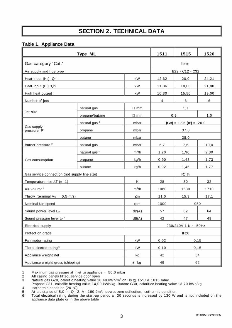
Table 1. Appliance Data
Type ML 1511 1515 1520
Gas category 'Cat.' II2H3+
Air supply and flue type B22 - C12 - C32
Heat input (Hs) 'Qn' kW 12,62 20,0 24,21
Heat input (Hi) 'Qn' kW 11,36 18,00 21,80
High heat output kW 10,30 15,50 19,00
Number of jets 4 6 6
natural gas ∅ mm 1,7Jet size
propane/butane ∅ mm 0,9 1,0
natural gas 1 mbar (GB) =17.5 (IE) = 20.0
propane mbar 37.0Gas supplypressure 'P'
butane mbar 28.0
Burner pressure 2 natural gas mbar 6,7 7,6 10,0
natural gas 3 m3/h 1,20 1,90 2,30
propane kg/h 0,90 1,43 1,73Gas consumption
butane kg/h 0,92 1,46 1,77
Gas service connection (not supply line size) Rc ¾
Temperature rise ∆T (± 1) K 28 30 32
Air volume 4 m3/h 1080 1530 1710
Throw (terminal VO = 0,5 m/s) ≤m 11,0 15,3 17,1
Nominal fan speed rpm 1000 950
Sound power level LW dB(A) 57 62 64
Sound pressure level LP 5 dB(A) 42 47 49
Electrical supply 230/240V 1 N ~ 50Hz
Protection grade IP20
Fan motor rating kW 0,02 0,15
*Total electric rating 6 kW 0,10 0,15
Appliance weight net kg 42 54
Appliance weight gross (shipping) ± kg 49 62
1 Maximum gas pressure at inlet to appliance = 50,0 mbar2 All casing panels fitted, service door open3 Natural gas G20, calorific heating value 10,48 kWh/m3 on Hs @ 15°C & 1013 mbar
Propane G31, calorific heating value 14,00 kWh/kg. Butane G30, calorificc heating value 13,70 kWh/kg4 Isothermic condition (20 °C)5 At a distance of 5,0 m, Q=2, A=160 2m², louvres zero deflection, isothermic condition,6 Total electrical rating during the start-up period ± 30 seconds is increased by 130 W and is not included on the
appliance data plate or in the above table

0108MLOOGBEN 4
Figure 1. DIMENSIONS
FRONT VIEW SIDE VIEW CONTROLS SIDE
PLAN REAR VIEW
Table 2. DIMENSIONS Re: FIGURE 1MODEL 1511 1515 / 1520
A Width overall 562 702B Depth overall 639 670C Depth of fan assembly 180 211D Width of casing (burner access) 330 470E Suspension socket centres 357 497F Centre Combustion air inlet to opposite side 247 317G Centre Combustion air inlet to controls side 315 385∅ Flue socket, diameter internal 80,0∅ Combustion air inlet socket, diameter internal 80,0
Legend figure 1.1. Combustion air inlet socket2. Flue connection socket3. Gas inlet connection
4. Electrical & controls inlets5. Service access panel6. Suspension sockets 1" BSPT

0108MLOOGBEN5
SECTION 3 INSTALLING
3.1 Figure 2 shows the clearances necessary to ensuresafety for combustibles and service access.
3.2 Ensure that the structural elements which will beused to suspend or support the appliance, areadequate to carry the weight of the appliance and itsancillary components i.e. flue system.
3.3 The location where the air heater is to be installed,must provide sufficient space around the heater forservicing and clearances for safety.
3.4 Ensure that the air heater is installed in a level plain.
3.5 Base mounting is optional; see figure 2 & 3. The airheater must be fastened securely to any basemounting arrangement. Note especially that theburner access on the ML series air heaters is via the
base of the appliance. A space of at least 500 mmmust be allowed for this purpose. Base supportelements must be installed respecting the criteriashown in figure 3.
3.6 Two threaded sockets are supplied on top ofthe appliance for suspension purposes. An alternativelocation for the socket on the controls side isavailable which serves if used, for better balancing.Alternatively the sockets can be removed and otherforms of suspension employed.
Specially designed wall brackets are available fromyour Reznor dealer.
3.7 After suspension, the air heater should be rigid so asto avoid placing a strain on the flue system, gasservices and electrical wiring.
Figure 2. INSTALLATION CLEARANCES, SUSPENSION & MOUNTING
Reznor wall bracket part number 80 28006
Installation clearances Suspension
Base mounting on wall bracket Showing stub duct for blow through a wall application

0108MLOOGBEN 6
Figure 3: BASE MOUNTING CRITERIA
SECTION 4. FLUE SYSTEM & COMBUSTION AIR SUPPLY
4.1 Flue systems must comply with the rules if forceand national and local regulations.
4.2 The products of combustion must be flued tooutdoor atmosphere. Common flues for more thanone appliance must NOT be used.
4.3 Combustion air should be taken from out-dooratmosphere, this improves the operationalefficiency of the heating system.
4.4 Flues and combustion air ducts where connectedto the air heater must incorporate a disconnectsection adjacent to the appliance to facilitateremoval of the venter assembly for servicing. Theflue system must therefore, be supportedindependently.
4.5 Dimensions and allowances in suggested flueingand combustion air intake arrangements are basedupon the use of smooth wall aluminium flue andcombustion air ducts and fittings.
4.6 Type C Appliances
4.6.1When using a concentric termination arrangement asfigure 4, then only an approved system usingReznor specified components may be used. Theseitems are manufactured from seamless aluminiumwith connection sockets fitted with silicone doubleedged seals, thus assuring, if the components areundamaged, leak free flue systems.
Important: This type of flue/Combustion air intakesystem is regarded as an integral part of the airheater therefore, departure from this method offlueing is in breach of the EC Gas ApplianceDirective.
4.6.2 Distance between the appliance and the concentricflue termination must not be greater than 9.0 m.When calculating the total length the followingequivalent data must be taken into account:1 elbow @ 45° = 1 m1 elbow @ 90° = 1,5 m.

0108MLOOGBEN7
4.7 Type B Appliances
4.7.1 If the air heater is to be installed as a B typeappliance i.e. air for combustion to be taken fromwithin the space to be heated, figure 5, then itmust be ensured that an adequate air supply forcombustion and ventilation is provided, inaccordance with the regulations and rules in force.
4.7.2 A horizontal distance between air heater and flueterminal and any combustion air intake duct, mustnot be in excess of 16 m.
Note: 2 Meters of vertical rise negates theresistance imposed by 1 meter of horizontal run.Runs exceeding 16m may be subject tocondensation forming within the flue.Equivalent lengths of flue fittings:Elbow @ 45° = 1 m.Elbow @ 90° = 1,5 m.Flue terminal ≤ 3.0 m. (dependant on type)
4.7.3 To ensure that the allowable resistance is notexceeded in the case of horizontal runs of flues, apositive rise from the air heater of 1° i.e. 17 mmper metre should be maintained.
4.7.4 If condensation is to be avoided, flues should beinsulated if they are installed in cold areas. The useof twin wall flues should also be considered.
4.7.5 When mechanical ventilation is used, it shall be bymechanical inlet with either mechanical or naturalextraction. Automatic means of control such asinterlocks must be provided. The function of otherventilation systems in the heated zone must betaken into account. At no time should a negativepressure environment exist in the zone, this canlead to a hazardous situation, whereby the airheater flue may act as a pressure relief.
4.7.6 The terminal of a vertical flue must extend 1 mabove a roof surface, flues must not terminatewhere combustion products might enter thebuilding. Terminals must be fitted to flues andcombustion air inlets. The combustion air inlet ifnot used must be protected with an access guard.
Figure 4 FLUE SYSTEMS FOR TYPE C APPLIANCESReznor concentric flue system
Horizontal terminal arrangement Vertical terminal arrangement
Use "Burfix" Ø 80 mm or "Mugro" 2000 Ø 80 mm
Mugro 2000 system horizontal or burfix80/125 horizontal
TYPE C12
Mugro 2000 system vertical or burfix 80vertical
TYPE C32

0108MLOOGBEN 8
Figure 5 FLUE SYSTEMS FOR TYPE B APPLIANCES
A guard must be fitted to combustion air inlet. A Ø 80 mm 90° elbow or Reznor option as shown
SECTION 5 GAS CONNECTION
5.1 Connection to the gas supply may only be carried outby suitably qualified persons. The gas installationmust comply with the rules in force using materialsappropriate for gas service installations.
5.2 Check that the gas category is in accordance withthe data described on the air heater and itspackaging.
5.3 An adequate gas supply sized to provide the dynamicpressure for the volume required by the air heater(s)is essential to maintain the nominal heat output ofthe appliance.
5.4 A 90° action service tap and, to facilitate servicing adisconnect union must be provided adjacent to theappliance, see figure 6.
5.5 Ensure that the gas service is provided with a filterand that it is tested and purged in accordance withprescribed practice prior to commissioning and takingthe air heater into service.
Figure 6 GAS CONNECTION DETAIL
WARNING: NEVER use a FLAME to test for GAS SOUNDNESS !!!

0108MLOOGBEN9
SECTION 6 ELECTRICAL CONNECTION
6.1 Electrical installation may only be carried out bysuitably qualified persons observing the rules in force.
6.2 Check that the electrical specification is inaccordance with the specified data on the air heater.A unique appliance wiring diagram is supplied as aseparate document attached to this one, plus anadditional copy attached to the air heater.
6.3 These appliances must be earthed.
6.4 A separate key lockable electrical isolator for eachheater must be provided adjacent to the applianceand in site of any person working on it. The isolatormust have a contact separation of at least 3.0 mmon all poles.
6.5 Ancillary controls are required to provide timed heatcycles, room comfort temperature level, frostprotection, override air circulation etc. These are notincluded with the appliance and should be orderedseparately.
6.6 Ensure when planning the external appliance controlcircuitry, that power will be supplied at all times tothe air heater, even when it is control switched in the'heat-off' mode. This is necessary to ensure that thefan can operate independent of the heating control.Therefore, Never incorporate automatic controls thatelectrically isolate the appliance.
NOTE: ML SERIES AIR HEATERS ARE SUPPLIED WITH EXTERNAL CONTROL CIRCUITS
BRIDGED. THE AIR HEATERS WILL OPERATE CONTINUOUSLY UNLESS THESE AREREMOVED AND TIME AND TEMPERATURE CONTROLS SUBSTITUTED FOR THEM
SECTION 7 COMMISSIONING
7.1 Commissioning general:
Reznor ML series air heaters do not requirecommissioning. Final testing during productionensures that if a suitable gas and electrical serviceand external controls have been connected to theappliance strictly in accordance with the instructionscontained in this document then it is ready to betaken into service. However, preliminary checks aslisted below are necessary to ensure safety andcorrect operation.
Understand the controls lay-out figure 10 and howthe heater works text 7.2
- A test for earth continuity
- A test for resistance to earth
- Zero voltage neutral to earth
- Check phase 230/240V to correct input terminal
- Correct external controls connections. Check thatwhen external controls are operated that aconstant electrical supply to the air heater ismaintained when the controls are in the OFF mode. This is necessary so that the air circulation fanmay operate at all times at the dictates of thethermally activated fan switch.
7.2 Understanding how the ML series air heaters work.
7.2.1 Reznor ML series air heaters employ the directburner ignition principle i.e. a separate ignitionburner is not used to light the main burner. Flamefailure protection is by the ionisation principle i.e.the ability of a suitable flame to pass an electricalcurrent between an electrode and the earthedburner assembly.
7.2.2 At the dictates of the external controls an electricalcircuit is made to an electronic burner control Theburner control checks to ensure a safe start ispossible by ensuring that the combustion airinduced draught fan ("venter") is stationary asmonitored by a differential pressure switch. If noair flow is proven, then the "venter" is switched onand the proving switch moves from the no airflowto the airflow position provided adequate airflowexists. This safeguards a blocked flue, faulty fluefan etc.
Once in the proved air flow condition the secondperiod of the ignition process commences this iscalled the pre purge time and lasts for ± 18seconds to ensure no unburnt gas is present in thecombustion chamber. If during this period, a flameor simulated flame is detected, lockout will occur. At the end of the pre purge period the ignitionsequence commences, a hot surface igniter heatsand glows, after a heating-up period of ± 23seconds ignition temperature will have beenreached and the main gas valves will open and theburner will light during a maximum time period notexceeding 5.0 seconds. Provided the flameremains adequate as sensed with a nominal flameionisation current of 1.5 - 3.2 µA the burner willremain alight until the external controls aresatisfied.
7.2.3 Simultaneously to the ignition circuit and gas valvecircuit being energised as described above,electrical power is supplied to an anticipator withinthe air circulation thermal fan control. Theanticipator advances the warm up of the thermalfan control thus ensuring that the air flow whenthe fan is switched on is temperate at ± 45°C. The air circulation fan will continue to run on afterthe burner has switched off to cool the heatexchanger.

0108MLOOGBEN 10
7.2.4In the event of the combustion air volume fallingbelow a safe level or in the event of the burnerflame being extinguished for any reason during arun cycle then safe shut down and lockout of theburner control will take place. Reset by manualintervention at a control panel or on the air heateris necessary to put the air heater back into service.
7.2.5In the event of overheating for any reason thermallyactivated fail safe overheat controls operate toswitch off the burner. The first control (LC1)switches off the burner and upon its coolingautomatically resets and the burner will relight. The second control (LC3) which operates at ahigher temperature setting, will switch off theburner and itself set to a lockout condition whichalso requires manual intervention to reset before itcan be restored to normal operational condition. This reset is on the right hand front side of theheater.
7.3 To check if the gas rate is correct, it is necessaryto connect a manometer to the burner pressuretest point. After the ML air heater has beenburning continuously for 10 minutes check thatthe burner pressure is in accordance with thatdescribed on the data plate. If it is low check alsothat the inlet gas pressure measured on the testpoint at the inlet to the gas control valve is correctaccording to the technical data in section 3. Adjust burner pressure as necessary.
7.6 To check if the flame current is adequate connecta DC micro ampere meter between terminals 17 &18 of the burner control after removing the bridgeconnector ; it should be set to the range 0-10 µA.A reading of 1.5 to 3.2 µ should be recorded.
WARNING: During operation the sensor circuitcarries mains electric current.
7.7 To light the air heater:
7.7.1Carry out the following procedure (which is alsodisplayed on the air heater casing).
To light the air heater with air discharge louvres setto open :
1. Turn on gas supply, including heater manualvalve (handle in line with valve).2. Switch on electrical supply to heater.3. Set room thermostat to desired temperature.4. Set time switch (if fitted) to an ON cycle.5. If heater reset button glows on the heater orremote control press reset button.
The heater should now light within 2 minutes.
N.B.: If the heater has been off for a prolongedperiod, up to three attempts to light it may benecessary. If the ML air heater still does not lightfollow fault finding procedure, section 9.
TO TURN OFF :
1. SHORT PERIOD : Turn room thermostat tolowest setting. To relight reset thermostat.
2. PROLONGED PERIOD : Turn room thermostat tolow setting. Turn heater manual gas valve OFF. After 5 minutes or when heater fan has stopped,turn off electricity supply to heater. Turn OFF thegas supply to the air heater. To relight follow thelighting instructions.
WARNING : The gas service tap must not beoperated except in emergencies or for servicing orprolonged periods of shutdown of the air heater.
7.7.2Upon completion of the commissioning, ensure theuser or a responsible person is aware of :
A) How to operate the air heater ;
B) The need for maintenance and servicing;
End of Commissioning Instructions
SECTION 8 SERVICING & MAINTENANCE
8.1 Attention: Inadvertent substitution or replacement ofcomponents similar to those specified orreplacement in a manner contrary to themanufacturer's designed method could constitute ahazard.
8.2 Before commencing servicing turn OFF the main gassupply to the air heater; switch OFF the mainelectricity supply to the air heater after the aircirculation fan has stopped.
8.3 General:
8.3.1 Reznor ML series air heaters require maintenanceand service at least once a year. More frequentservicing may be required dependent upon theenvironmental circumstances where the air heater(s)is installed. Advise the user of recommendedservice frequency. Regular inspection isrecommended initially especially in dirty areas toassess the servicing requirement frequency. Refer
to the illustrations provided by figure 10 forcomponent and visual instruction as a guide tocarrying out service work. Items that requireinspection during servicing are :
8.3.2 All components and surfaces both inside and outsideof the air heater require cleaning. Check for damagewhich could affect the continuing prolonged use ofthe air heater especially the bottom burner accesspanel. Check condition and security of flue andcombustion air system. Check for security andworthiness of the suspension or mounting system.
8.4 Check condition of total air heater electrical circuitincluding isolator. Look for damage to conduits/conductor insulation. Check for loose terminals andescaped conductor strands. Ensure that noconductors are under tension. Note condition of allelectrical components.NOTE : Fan motors are lubricated for life and do notrequire further lubrication.

0108MLOOGBEN11
8.5 It is necessary to remove the burner rack assemblyto clean the burner ribbons and to inspect and cleanthe inner surfaces of the heat exchanger.
To remove the burner rack assembly refer to figure7, 6 step procedure
A) Remove Qty. 4 screws and remove bottompanel.
B) Spring inwards left hand and right hand burnerrack locators and lower front end of burner rackto below level of casing.
C) Ease burner rack toward front of air heater untildisengaged from injectors.
8.5.1 With the burner assembly removed, it is nowpossible to inspect the heat exchanger with the aidof an inspection lamp and mirror. Cleaning can becarried out using a stiff flue brush and vacuumcleaner.
8.5.2 Inspect the burner assembly for damage, corrosionand cleanness.
With a brush and vacuum clean all exposed surfacesand flame ports. If injectors are dirty these can beremoved after disconnecting the gas manifold fromthe air heater. Any sticky deposits on the injectorsshould be removed using acetone. Do not clean the injector with a sharp metal object.The orifice is machined to fine limits.
8.5.3 Inspect the igniter element assembly Fig.9 checkingespecially the condition of the insulation. If in doubtabout its condition it is wise to renew this item.
N.B. The igniter element is an extremely fragiledevice. Handle with care.
8.6 To remove the burner manifold assemblyincorporating the gas burner injectors and multi-functional gas valve. Figure 10 key 21.
A) Unscrew Qty 4 screws securing adaptor elbowgas inlet on valve or if gas service connectionwill permit unscrew disconnect union fittingoutside.
B) Un-clip wires leading to gas valve operatorsnoting their appropriate terminal points forreconnection.
C) Remove Qty. 2 hexagon nuts securing manifold.
D) Withdraw manifold sideways.
Note: Burner rack assembly must be removedbefore manifold can be removed.
8.7 To service the air circulation fan figure 10 key 29
To clean only. The electrical wire connectionbetween the fan motor and the appliancetermination is long enough to allow removal of thefan assembly for cleaning purposes. To preventstrain on the conductors the fan assembly shouldbe secured with a string or cord whilst carrying outcleaning.
To replace components of the fan assembly whenit is necessary to disconnect the motor, the motorlead wire should be disconnected at the motorend.
Figure 7: ACCESS TO AND REMOVAL OF THE BURNER ASSEMBLY
Legend:1 & 2.Remove 4 screws front & rear3. Lower base tray4. Spring retaining clips to release burner front end and lower (5) at the same time pulling forward (6)

0108M
Figure 8 FLUE GAS FAN (venter) COMPONENTS
Figur
Legend :1. Fan housing1. Impeller1. Motor mounting
plate1. Heat sink rotor1. Motor
LOOGBEN 12
e 9 IGNITER ASSEMBLY DETAIL8.8 To renew the motor capacitor. Fig.10 key 24.
This is located behind the motor end plate, accessis by removal of two screws. The capacitor issecured in a spring clip and wire connection is by1/4 "Faston" electrical connectors.N.B. : ensure the "milor plastic" insulation ring fittedinside the motor terminal housing is correctlyrelocated should this become dislodged whilstchanging the capacitor and ensure the capacitor endbolt touches the motor terminal housing thusensuring the capacitor electrical terminals do nottouch the opposite side of the motor housing.
8.9 To service the combustion air fan ("Venter") Fig.10key 3 and Fig.8A) Disconnect wires at the fan motor .fig.10 key
4.B) Unscrew Qty. 3 cross head screws securing
motor and mounting plate to venter scroll.
Fan impeller critaicaldimensions

0108MLOOGBEN13
C) The fan impeller is attached to the motor shaftby a ∅ 4.0 mm socket grub screw. This canbe released using a 2 MM AF hexagon wrench(allen key).
D) It should be noted that a groove is machinedon the outer end of the motor shaft figure 8when the fan impeller is pushed onto the motorshaft until the groove is visible the correct endlocation of the fan impeller into the fan scroll isassured. Ensure the securing grub screw istight after service.
E) Check condition of motor and note especiallyfor excessive end float of motor shaft, whichcould indicate wear.
8.10 To renew thermal overheat control LC3. Fig. 10 key12.
8.10.1 A) Disconnect wires at terminals on controlB) Access capillary bulb through air outlet louvresand un-clip from its bracket. If ducted via accesspanel.C) Unscrew Qty 2 screws which secure sealingplate. Fig. 7 key 12.D) Remove reset push button cover cap.E) Unscrew hexagon retaining nut and removecontrol.
N.B. : When fitting a new thermal overheat controldo not bend capillary on a less than 20 mm radius.
8.11 To renew combustion air proving pressuredifferential switch Fig. 7 key 7.
A) Disconnect wires leading to terminalsB) Disconnect reference port tubes at pressureswitch endC) Remove Qty. 3 screws securing mountingbracket to air heaterD) Pressure switch fixing screws are now accessible from rear of mounting bracket.
N.B.1: Ensure reference port tubes are correctlyreconnected when replacing or renewing pressureswitch:Port P1 on switch to lower reference Key 6.Port P2 on switch to top reference Key 6
N.B.2 : Combustion air proving switch operatingpressures. Cutout = 68 Pa.To check this it is necessary to connect amanometer in the air sensing circuit by use of a φ9.0 mm tee piece fitting; ensure a positive seal ismaintained. The switch should not be adjusted for any reason. The unique part number of this device ensures thecorrect differential pressure is maintained thusassuring good combustion.
8.12 To renew electronic burner control Fig. 10 key 14.A) Disconnect wires at control end leading toignition device. Fig. 7 key 17.B) Carefully unplug multi-point terminal connectorsby pulling off key 14.C) To remove unscrew Qty. 2 control fixing screwsD) Control is now released.
N.B. : This is not a repairable item therefore, noattempt should be made to do so. Replacements ofthis unique specification must be obtained fromReznor.
8.13 To renew or replace thermal fan control fig. 10 key11 and/or thermal limit control fig. 7 key 8, simplydisconnect the "Faston" wire terminals and unscrewQty 2 screws in each device to remove from airheater casing.
8.14 To renew or replace Ignition device assembly fig. 10key 17 and Fig.9.
A) Disconnect lead wires at burner control end. Fig. 7 key 14.
B) Unscrew Qty. 2 screws securing the assemblyto the air heater
D) Withdraw the assembly carefully from thecombustion chamber.
8.15 After completion of any service or maintenancework re-commission the air heater in accordancewith section 5 of this document.
8.16 Check functionality of external controls and reset inaccordance with users preferences.
End of servicing instructions

0108MLOOGBEN 14
Figure 10 COMPONENT PARTS LOCATION
Legend figure 10:
1. Flue outlet2. Venter housing3. Venter motor4. Fan impeller5. Suspension socket 1" BSP6. Combustion circuit reference pressure points7. Thermal overheat control and reset switch LC38. Isolation transformer (not GB)9. Burner lock-out reset switch10. Wiring terminals11. Thermal limit control LC112. Thermal fan control FCR13. Fuse in terminal assembly14. Automatic burner control
15. Capillary for LC316. Relay for isolation transformer (not GB)17. Igniter assembly18. Multi-functional gas control19. Burner pressure test point20. Burner manifold21. Combustion air inlet socket22. Gas control solenoids23. Air circulation fan24. Air circulation fan motor25. Combustion air proving differential switch26. Inlet gas connection Rc ½27. Burner gas pressure adjustment access28. Test point for combustion air temperature
END OF SERVICE INSTRUCTIONS

0108MLOOGBEN15
SECTION 9 : ML Short Parts Listing
ITEM DESCRIPTION MAKERS REF. PART NO USED ON
GAS
1 Gas Valve "SIT" 830040 ½" 03 25250 Natural & Propane gas
2 Burner Jet 170 = φ 1.7 mm 07 25801 170 Natural Gas
3 Burner Jet 090 = φ 0.9 mm 07 25801 090 Propane/Butane 15-11 / 15-15
4 Burner Jet 100 = φ 1.0 mm 07 25801 100 Propane/Butane 15-20
5 Test Nipple _ NPT x 9mm 07 25264 02 All
6 Gas Valve 90° Flange ½" 400104B 03 24982 All
7 Igniter Assembly Norton 240V 36 25216 All
ELECTRICAL
8 Burner Control "Honeywell" S45-70LS 03 25317 All
9 Overheat Control LC3 LSI 541510 86° 03 24958 All
10 Limit Control LC1 60TII500 283 03 24970 All
11 Thermal Fan Control FCR TOD29 TI2(250V) 03 25166 All
12 Terminal Assembly Entrelec 06 41635 All
13 Fuse 2A Fast DIN41571 06 00157 2A All
14 Connector Gas Valve V1 03 25250 V1 All
15 Venter assembly ES 30 + fan & house 36 79015 All
16 Fan Motor MAC 30 W6 01 26026 1520 All
17 Fan Motor Capacitor 3 mfd 400V 01 25598 03 MF 1515 - 1520
18 Fan Motor Capacitor 2 mfd 400V 01 25600 02MFD 1511
19 Lock-out indicator/switch 5A 60 61988 All
20 Air Pressure Switch Honeywell C6065F 30 60607 68 All
AIR HANDLING
21 Fan motor Elnor RIBX 135/EV1 01 25620 01 1511
22 Axial fan N4-305-28-½ 02 25702 1511
23 Fan Assembly MAC 30W 625 02 26030 15 1515
24 Fan Assembly MAC 30W 635 02 26030 20 1520
25 "Venter" Complete ES 30-986 36 79015 All
26 "Venter" Wheel (impeller) ES 30 02 25730 All
27 "Venter" Scroll (housing) ES 08 17509 All
28 Air Fan 350 x 25° 02 26028 15 1515
29 Air Fan 350 x 35° 02 26028 20 1520
MISCELLANEOUS
30 LC3 Capillary Seal Plate - 08 07727 All
31 Gasket for item 31 (LC3) - 06 07726 All
32 Gasket for item 28 (venter) - 08 17551 All
33 Sampling Pressure Point M8 07 25811 02 All
34 Silicon Tubing φ 5 - 8 x 1.0m length 06 20224 cm All
35 Suspension Sockets 1" BSP (R1)/M10 35 20003 Optional

0108MLOOGBEN 16
SECTION 10 GAS CONVERSION INSTRUCTIONS
10.1 Reznor ML series air heaters are designed to operateon Natural-Propane-Butane gas and will be suppliedas ordered for the gas type specified.
10.2 In the event it is required to convert to a differentgas type to what has been supplied, the conversionof the gas burner and gas controls is necessary. AReznor conversion kit must be used and comprisesthe items illustrated in fig.11.
10.3 When converting from natural gas to Propane orButane gas the gas regulator on the gas valveshould be adjusted to maximum pressure, i.e.screwed inwards to stop position, and then sealedto prevent re-adjustment.
N.B. Normally natural gas air heaters are suppliedwithout air shutter assemblies. If converting tofrom propane or butane to natural gas set air shutteras below 18.0mm open.
10.4 To carry out the conversion, refer to the appropriateinstructions in section 8, specifically paragraphs 8.5and 8.6 which explain appropriately the accessibilityand testing requirements.In addition to changing the gas valve and burnerinjectors, it is necessary to reset the burner ribbonaeration shutter as appropriate & place thenecessary over stickers. Carry out thecommissioning procedure stated in section 7 of thisdocument when conversion is completed.
Fig. 11 Gas Conversion Kit Items.
DATANGPROBUetc

0108MLOOGBEN17
SECTION 11 FAULT FINDING
11.1 Air heater will not light :
A) Read lighting instructions;
B) Check gas supply is turned on;
C) Check electricity supply is switched on;
D) Check burner control lockout condition: Fig.10Key 9 local or remote. Reset as applicable
E) Check thermal overheat control lockout condition:Fig.10 Key 7. Reset local
F)Combustion air fan not rotating: check free to run
G) Combustion air fan running air flow not beingsensed:Check connections to reference ports on heaterand pressure switch - check connection tubes notperforated - check no condensation in tubes -check flue is not blocked - check combustion airinlet duct is not blocked - check flue length &combustion air duct length Re. section 4 - checkoperation of pressure switch by: disconnectingtube and gently blowing into tube, switch shouldbe heard to click or metered to indicate switchopening/ closing
N.B. Terminals 1 & 2 normally closed position no airflow.Terminals 1 & 3 normally open and close on positiveair flow 6.5 - 7.5 mbar.Faulty pressure switch! renew.
H) Faulty burner control! renew.
J)Faulty ignition device or wire connection: checkearth potential/continuity, Faulty! Renew
K) Faulty gas valve : renew.
11.2 Heater tries to light igniter glows brightly
Gas turned off ?Air in gas supply - check purged supply.Gas pressure inlet too low/high - check, if necessarycall gas supplier.Gas valve not operating: check wiring - check valve- check burner control renew as appropriate.
11.3 Burner lights & goes out immediately :
Insufficient flame proving current: check ignitiondevice & wiring measure flame current 7.6: faultyburner control - flame sensor electrode incorrectlylocated!
11.4 Cool air during operation - continuously when burneris off:
A) Ensure specification is not for constant run fan(CRF);
B) Low gas pressure - check, adjust if not inaccordance with data plate;
C) Manual fan override switch if fitted set to on -check and switch off;
11.5 Air circulation fan will not run:
A) Open circuit - check wiring;
B) Faulty thermal fan control switch - check renew;
C) Defective capacitor - check renew;
D) Defective motor - check renew;
E) Fan blocked - check it rotates freely.
11.6 Air circulation fan runs and stops while gas burnerremains alight:
A) Thermal fan control switch faulty or incorrectlywired - check circuit against wiring diagram;
B) Faulty fan control switch - renew;
C) Faulty fan motor - renew;
D) Low ambient air temperature causing fan controlswitch to cool and open circuit - maintain higherambient temperature near the air heater. Thissymptom will cease as the heating periodlengthens due to gradual rise of air-ontemperature.
11.7 Air circulation fan cycling on its thermal overloadprotector:
- Check electrical current rating - check power supply- check fan rotates freely and is not imposing an abnormal load - check capacitor is operational.
11.8 Air heater cycles on thermal overheat control LC1:
A) Control faulty - renew;
B) Air flow restricted - clean fan assembly; checklouvre setting;
C) Fan faulty - renew;
D) Gas rate too high - adjust burner gas pressure;
E) Local ambient air temperature near the air heatertoo high - above 30° check for stratification -install a Reznor "Maximizor" and save energy!
11.9 Air circulatory fan keeps running :
Faulty fan control : renew.Gas valves open : check valve or wiring fault byremoving wires at valve solenoid terminals byunplugging.Faulty valve : renew.Faulty wiring : correct.
End of fault finding guide.

0108MLOOGBEN 18
SECTION 12 HEALTH AND SAFETY STATEMENT
Health and Safety Information for the Installer and Commissioning-Service Engineer
Under the Consumer Protection Act 1987 and Section 6 of the Health and Safety at Work Act 1974 we hereby provide thefollowing information on substances hazardous to health. Product range reference: "ML Series"
12.1 During first firing some smoking may occur, this isdue to the burning off of protective/lubricating oilsused during appliance production. Most of this willhave been removed during the production testingprocess.It is a wise precaution to ensure thatadequate ventilation is provided during the initialfiring and throughout the commissioning period,this is particularly important if the discharge air isto blow into a confined space. This smoking doesnot constitute a poison hazard.
12.2 Reznor products contain no asbestos; copper is notemployed in gas carrying components; solderwhich has a melting point below 450°C is notused; paints for corrosion protection anddecoration are heat cured and contain no lead.
12.3 The above appliances meet the Electrical Safetyrequirements of EN60 335 Pt 1 1988.
12.4 Small quantities of adhesives and sealants used inthe product are dried and cured and present noknown hazard.
12.5 Insulation and Seals.
Material: Synthetic Ceramic Fibre with Organicbinder.Description: Tapes and PapersKnown hazards: Some people can suffer reddeningand itching of the skin. Fibre entry into the eyeswill cause foreign body irritation.Inhalation will cause irritation to the respiratorytract. As with any dust pre-existing respiratorycondition and lung diseases may be aggravated.
Prolonged exposure for the purposes envisagedpertaining to this Reznor product is not anticipated.
Precautions: Wear protective gloves when handling.If abrading and dust is generated suitable protectiverespirators must be used.People with a history of skin complaints may besusceptible to irritation.Dust levels are only likely when the material isabraded.In general normal handling and use for this purposewill not present discomfort. Follow good hygiene practices, wash hands before consuming food orusing the toilet.
First Aid: Medical attention must be soughtfollowing eye contact or prolonged reddening of theskin.
12.6 Thermostat.
Material: Illuminating Kerosene.Description: Sealed phial contains a smallquantity in liquid form.Recognition: Colourless liquid, paraffinoil/petroleum hydrocarbon odour.Characteristics: Non-corrosive, flammable withno poisonous reference - CH poison Class 3Precautions: Avoid handling. This product canirritate and defat the skin. Prolonged contact maycause dermatitis. Avoid breathing vapour. Avoideye contact.Do not ingest.
First Aid: Skin. Wash thoroughly with soap andwater.Eyes. Rinse immediately with copious amounts ofclean water.
Ingestion: Seek medical advice.
NOTE: If skin irritation persists seek medicaladvice.
12.7 Electrolytic CapacitorTwo types are used by random selection:
Recognition: 1.Plastic enclosure 2.Aluminiumenclosure
Material: Contained liquid electrolyte
Known hazards: Electric shock possible ifcharged.
Precautions: Discharge to ground/earth. Do notincinerate.
First Aid: Treat for electric shock if affected.
END OF HEALTH AND SAFETY STATEMENT

0108MLOOGBEN19
SECTION 13 USER INSTRUCTIONS FOR OPERATING AND LIGHTING
NOTE: Please keep a copy of this document near your airheater!
13.1 Your Reznor ML series air heater was intended tobe installed,commissioned and tested in accordancewith these manufacturer's writtenrecommendations.
13.2 In the interest of safety and user satisfaction it isimportant that this document is read andunderstood. If in any doubt, consult your installeror your local gas regional supplier.
13.3 It is in your interest to ensure proper service andmaintenance is carried out on a regular basis. Reznor suggests at least once a year.
13.4 In the event of difficulties in resolving any of thesematters, please do not hesitate to contact Reznoror their official distributor.
13.5 About your air heater:
13.5.1 Reznor ML series air heaters are "state of the art"gas fired appliances and incorporate an atmosphericburner which can use air for combustion fromoutdoors provided the combustion air inlet isducted. This is identified by 2 round pipes/ductsbeing connected to the rear of the air heater.Products of combustion are vented to outdooratmosphere via permanently connected forceddraught flue.
13.5.2 This heater has not been designed for use with airdistribution ducting to provide heat for more thanone room.
13.5.3 The location of the air heater should be maintainedat normal atmospheric pressure. Changes to thebuilding after air heater installation should haveregard to the heating installation, i.e. structuralchanges causing excessive draughts from doors,windows. Other air handlers and installation of airextraction equipment which may cause a negative pressure environment which can seriously affectthe operation of this type of air heater. Especiallyif combustion air supply is unducted.
13.5.4 The space heating process using Reznor ML seriesair heaters is for air to be circulated through theappliance whereby it gains heat from a heatexchanger, which is directly discharged into thespace to be heated.The air is eventually recirculatedthrough the appliance, thus an unobstructed pathfor the circulation of the air must be maintained. This is particularly important if the air heater hasbeen installed to blow through the wall betweentwo rooms.
13.6 How the air heater works:
Gas is burned at an atmospheric burner which firesinto a multiplex combined combustion/heatexchanger. The gas burner is controlled by a doublegas valve via an automatic electronic burnercontrol, which is switched via external controls i.e.a room thermostat and or a time switch.
Reznor ML air heaters incorporate a hot surfaceignition device and is protected by electronic flame
sensing. Safe operation of the air heateroperation is automatic following the dictates ofthe external timing and temperature controls.
Safety against overheating is assured by theinclusion in the controls circuit of two thermaloverheat controls. There is an automatic recyclecontrol which protects against low air flow i.e.clogged air ways, fan failure! The second controlbeing a super overheat control which locks outand switches off the burner in the event ofgross overheating for any reason. Manualintervention to reset is necessary should thesuper overheat operate. Resetting of theelectronic burner control may also be required.
When the main burner fires and warms the heatexchanger, the heat is sensed by a thermallyactuated fan control which switches the fan onwhen the air temperature reaches approximately45° C. At the end of a heating cycle when theburner is switched off, the air circulation fan willcontinue to run until the air heater has cooled toa safe condition. Thereafter the fan will remainoff until the next cycle is initiated. Shouldresidual heat within the appliance or highambient temperature in the vicinity of theappliance exist then, the fan will runautomatically to maintain the appliance in a coolcondition.
13.7 To light the air heater:
1. Turn on the gas supply to the air heater;
2. Switch on the electricity supply to the airheater;
3. Ensure time switch if fitted is set to an ONcycle;
4. Adjust control/room thermostat to desiredtemperature;
5. Air heater will light automatically when theroom thermostat calls for heat;
6. If the air heater does not light:
a) Check that the burner control does not requireresetting. An indicator light glows on the airheater and if fitted the remote control panelwhen in lock out condition press & release toreset.
b) Check at the air heater if the thermal overheat(limit) control requires resetting refer figure12
NB: If a remote control reset is not fitted asdescribed in (a) above, check and reset ifnecessary the reset burner control on the airheater.
To turn off the air heater for short periods:
1) Adjust room thermostat to lowest setting.Toturn off the air heater for a prolonged period:
2) Carry out operation 1 above and wait fiveminutes and then switch OFF the main

0108MLOOGBEN 20
electric supply to the air heater provided the aircirculatory fan has stopped.
3) Turn off the gas supply to the air heater.
13.8 IMPORTANT
If the thermal overheat (limit) control requiresresetting & doing so restarts the air heater, waituntil it warms up to thermal equilibrium to ensurethe overheat control does not reactivate and lockout. If it does and the room air temperature nearthe air heater is less than 30° C then switch OFFthe air heater & call for service.
13.9 Air circulation
Some Reznor unit air heaters have fans connectedto a remote override switch. This enables cool airto be used for circulation purposes when the airheater is not used for heating purposes e.g. insummer months.To use this feature :
a) Switch ON mains electricity supply to the airheater.
b) Switch ON the manual override switch. This maybe on a remote control panel.
13.10 Maintenance and servicing
Maintenance and service must only be carriedout by competent persons. Periods betweenservice are dependent upon the localenvironment where the air heater is installed. Regular inspection is recommended initially toascertain routine service intervals.
The service instructions in section 8 of thisdocument suggest that the engineer informs theuser of his findings. Where the installedenvironmental circumstance change e.g.different processes being carried out in afactory, the service interval should bereconsidered. If in doubt, ask your installer,service undertaking or the manufacturer aboutinspection and service intervals. The air heatershould be serviced at least once every heatingseason. Ensure that any combustion air ventsfitted to the building in which the air heater isinstalled are unblocked at all times. Periodicallycheck to ensure that the outer casing of the airheater is clean; excessive dust might constitutea hazard.
13.11 Warning : Never switch off the mains electricalsupply to the air heater unless the mains gassupply is turned off.
Figure 12: Lockout reset locations

0108MLOOGBEN21
Reznor® ML SERIES
ONE OF THE Reznor GENERATION OF CE MARKED GAS FIRED
ENERGY EFFICIENT AIR HEATERS
BEST USED WITH Reznor OPTIONAL ELECTRONIC CONTROL PANELSSAVE ENERGY AND OPTIMISE THERMAL COMFORT