gas boiler system commissioning checklist & service record v1 … · 2019-06-14 ·...
TRANSCRIPT

Users Instructions
Installation &ServicingInstructions
THESE INSTRUCTIONSTO BE RETAINEDBY USER
Vokèra is a licensed member of the Benchmark schemewhich aims to improve the standards of installation andcommissioning of domestic hot water systems in the UK.
VerveHigh efficiency system boiler
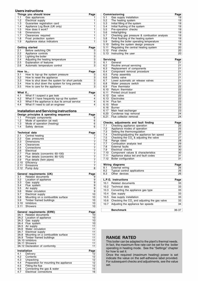
Users instructionsThings you should know Page1.1 Gas appliances 11.2 Electrical supply 11.3 Guarantee registration card 11.4 Appliance Log Book (UK only) 11.5 How does it work? 11.6 Dimensions 11.7 Clearances required 11.8 Frost protection system 11.9 Appliance status indicators 1
Getting started Page2.1 Before switching ON 32.2 Appliance controls 32.3 Lighting the boiler 32.4 Adjusting the heating temperature 32.5 Explanation of features 32.6 Automatic temperature control 3
How to... Page3.1 How to top-up the system pressure 33.2 How to reset the appliance 33.3 How to shut down the system for short periods 33.4 How to shut down the system for long periods 33.5 How to care for the appliance 3
What if... Page4.1 What if I suspect a gas leak 44.2 What if I have frequently top-up the system 44.3 What if the appliance is due its annual service 44.4 What if I need to call an engineer 4
Installation and Servicing instructionsDesign principles & operating sequence Page1.1 Principle components 61.2 Mode of operation (at rest) 61.3 Mode of operation (heating) 61.4 Safety devices 6
Technical data Page2.1 Central heating 72.2 Gas pressures 72.3 Dimensions 72.4 Clearances 72.5 Connections 72.6 Electrical 72.7 Flue details (concentric 60-100) 72.8 Flue details (concentric 80-125) 72.9 Flue details (twin pipes) 72.10 Efficiency 72.11 Emissions 72.12 Pump duty 8
General requirements (UK) Page3.1 Related documents 93.2 Location of appliance 93.3 Gas supply 93.4 Flue system 93.5 Air supply 93.6 Water circulation 93.7 Electrical supply 103.8 Mounting on a combustible surface 103.9 Timber framed buildings 103.10 Inhibitors 103.11 Showers 10
General requirements (EIRE) Page3A.1 Related documents 103A.2 Location of appliance 103A.3 Gas supply 103A.4 Flue system 103A.5 Air supply 113A.6 Water circulation 113A.7 Electrical supply 113A.8 Mounting on a combustible surface 113A.9 Timber framed buildings 113A.10 Inhibitors 113A.11 Showers 113A.12 Declaration of conformity 11
Installation Page4.1 Delivery 124.2 Contents 124.3 Unpacking 124.4 Preparation for mounting the appliance 124.5 Fitting the flue 124.6 Connecting the gas & water 154.7 Electrical connections 16
Commissioning Page5.1 Gas supply installation 195.2 The heating system 195.3 Initial filling of the system 195.4 Initial flushing of the system 195.5 Pre-operation checks 195.6 Initial lighting 195.7 Checking gas pressure & combustion analysis 195.8 Final flushing of the heating system 195.9 Setting the boiler operating temperature 195.10 Setting the system design pressure 195.11 Regulating the central heating system 205.12 Final checks 205.13 Instructing the user 20
Servicing Page6.1 General 216.2 Routine annual servicing 216.3 Replacement of components 216.4 Component removal procedure 216.5 Pump assembly 216.6 Safety valve 216.7 Lower automatic air release valves 216.8 Water pressure switch 216.9 Flow thermistor 226.10 Return thermistor 226.11 Printed circuit board 226.12 Gas valve 226.13 Electrodes 226.14 Flue fan 236.15 Mixer 236.16 Burner 236.17 Main heat exchanger 236.20 Condense trap removal 246.21 Flue collector removal 24
Checks, adjustments and fault finding Page7.1 Checking appliance operation 257.2 Appliance modes of operation 257.3 Setting the thermoregulation 267.4 Checking/adjusting the appliance fan speed 277.5 Checking the CO2 & adjusting the valve 277.6 Range rated 287.7 Combustion analysis test 297.8 External faults 307.9 Electrical checks 307.10 Component values & characteristics 307.11 Appliance status led and fault codes 317.12 Boiler configuration 31
Wiring diagrams Page8.1 External wiring 268.2 Typical control applications 268.3 Other devices 26
L.P.G. instructions Page10.1 Related documents 3310.2 Technical data 3310.3 Converting the appliance gas type 3310.4 Gas supply 3310.5 Gas supply installation 3310.6 Checking the CO
2 and adjusting the gas valve 33
10.7 Adjusting the appliance fan speeds 34
Benchmark 36-37
RANGE RATEDThis boiler can be adapted to the plant’s thermal needs.In fact, the maximum flow rate can be set for the boileroperating in heating mode. See the “Settings” chapterfor how to set it.Once the required (maximum heating) power is setindicate the value on the self-adhesive label provided.For subsequent checks and adjustments, see the valueset.

1
USERS INSTRUCTIONS
1.1 GAS APPLIANCESGas Safety (Installations and Use) Regulations (UK).In the interests of your safety and that of others it is a legalrequirement that all gas appliances are installed and correctlymaintained by a competent person and in accordance with thelatest regulations.
1.2 ELECTRICAL SUPPLYPlease ensure that this appliance has been properly con-nected to the electrical supply by means of a double poleisolator or un-switched socket, and that the correct size of fuse(3 AMP) has been fitted.Warning: this appliance must be earthed!
1.3 GUARANTEE REGISTRATION CARDPlease take the time to fill out your guarantee registration card.The completed warranty card should be posted within 30 daysof installation.
1.4 APPLIANCE LOG BOOK (UK only)A logbook section can be found at the rear of the applianceinstallation booklet. This important document must be completedduring the installation/commissioning of your boiler. All GASSAFE registered installers carry a GAS SAFE ID card, and havea registration number. These details should be recorded in theBenchmark logbook section within the installation booklet. Youcan check your installers details by calling GAS SAFE direct on08004085500. Failure to install and commission the appliancein accordance with the manufacturers instructions mayinvalidate the warranty. This does not affect your statutoryrights.
1.5 HOW DOES IT WORK?Your Verve boiler supplies heated water to your radiators andhot water to your hot water tank.The central heating is controlled via a time clock and anythermostats that your installer may have fitted.The boiler will light when it receives a request from the timeclock via any thermostat that may be installed.Your Verve boiler lights electronically and does not have a pilotlight.In the unlikely event of a fault developing with your boiler, thesupply of gas to the burner will be terminated automatically.For the installation it is recommended to use an hydraulicseparator to supply the heating (fig. 20); in case of hot water usea three way valve to supply the tank (fig. 20)
Dear CustomerYour Vokèra Verve boiler has been designed to meet and exceed the very latest standards in gas central heating technology,and if cared for, will give years of reliable use and efficiency.Please therefore take some time to read these instructions carefully.Do’s and Don’t’s- Do ensure that the system pressure is periodically checked- Do ensure that the boiler should not be used by children or unassisted disabled people- Do ensure that you know how to isolate the appliance in an emergency- Do ensure that you are familiar with the appliance controls- Do ensure that your installer has completed the appliance log book section- Do not attempt to remove the appliance casing or gain internal access- Do not hang clothes etc. over the appliance- Do not forget to have the appliance serviced annually.
This booklet is an integral part of the appliance. It is therefore necessary to ensure that the booklet is handed to the personresponsible for the property in which the appliance is located/installed. A replacement copy can be obtained from Vokèracustomer services.
INTRODUCTION
1.6 DIMENSIONS
1.7 CLEARANCES REQUIRED
ABOVE see section 4BELOW see section 4LEFT SIDE 100 mmRIGHT SIDE 100 mmFRONT 600 mm
VerveHEIGHT 858 mm (*)WIDTH 553mmDEPTH 284 mm
1.8 FROST PROTECTION SYSTEMThe Verve is equipped with a built-in frost protection system,this enables the boiler to over-ride the time controls – even ifswitched off – and operate the burner and/or pump, should thetemperature drop below 50C for the main. In particular theburner will be in ON status until the main temperature reaches35°C for CH appliance.Please note that the frost protection system is designed toprotect the appliance only, should frost protection be requiredfor the heating system, additional controls may be required.NOTEThe frost protection system is reliant on the appliance havinga permanent electrical supply, and being in a non-faultcondition.
1.9 APPLIANCE STATUS INDICATORSYour boiler is equipped with 3 status LED indicators, the GreenLED indicates that the flame is present, the Red LED indicatesthe appliance has detected a fault, whilst the Yellow LEDindicates that there is Servicing operation in progress, andwith a display that indicates the operating temperature andthe fault codes.
1. THINGS YOU SHOULD KNOW
(*) with hydraulic cover

2
Fig. 1
BOILER STATUS LED
Green LED Boiler is working/responding to a heating/hotwater request
Red LED Boiler has identified a fault and has failed-safe.Refer to instructions on how to reset
Yellow LED Service operation
DISPLAYIndicates the operating temperature and the fault codes
PRESSURE GAUGEEnsure the system pressure is set correctly (minimum 0.5-bar)
MODE SELECTOR SWITCH/HEATING TEMPERATURESELECTORMode selector switch:
GREENLED
Boiler at OFF/standby - Select this position when you wantthe boiler to be switched off for short periods (days) or if theboiler requires to be reset
Heating & hot water - Select this position when you want theboiler to respond to a heating request from the time-clockprogrammer and hot water request from the tank thermostat
Heating temperature selector: move the selector clockwiseto increase the heating outlet temperature, or counter-clockwiseto reduce the temperature range:- 40°C-80°C for standard systems- 20°C-45°C for floor heating heating (contact Vokera technicalif used in conjunction with DHW cylinder)The automatic temperature control function (SARA) is set withinposition 4 and 6 (55 ÷65 °C), the display indicates the heatingwater temperature
Pressure gauge shows the current pressure of your heatingsystem, the gauge should be set between 1,5 and 2.0 BAR.When the appliance is operating the gauge may rise or fallslightly, this is quite normal. The minimum permissible level forthe safe and efficient operation of the appliance is 0.5 BAR.Should the pressure fall below 0.5 BAR, the boiler maylockout.
correctpressure
value
Hot water only: only used in conjunction with the optional 3way valve kit.
��MODE
SELECTORSWITCH
REDLED
HEATINGTEMPERATURE
SELECTOR
HYDROMETRE
DISPLAY
DISPLAYDescription of the icons
System loading - this icon is visualised together witha fault code A 04Heat-adjustment: indicates the connection to anexternal probeFlame failure - this icon is visualised together with afault code A 01Irregularity: indicates any operating irregularities,together with a fault codeHeating operationDomestic hot water operation (optional)Anti-freeze: indicates that the anti-freeze cycle hasbeen activated
�� Heating/domestic hot water temperature or fault code
DISPLAY
YELLOWLED

3
2.1 BEFORE SWITCHING ONBefore switching the appliance on, please familiarise yourself with:- how to isolate the appliance from the gas, water, and elec-
tricity supplies;- how to check and top-up – if necessary – the system water
pressure;- the time clock or programmer (if fitted);- any external thermostats and their functions;- the appliance controls.
2.2 APPLIANCE CONTROLS (see fig. 1)The appliance controls are situated on the lower front of theappliance. The appliance controls include:- pressure gauge;- appliance mode selector;- temperature selector;- display- burner ON mode (green);- fault indicator (red);- servicing mode indicator (yellow)- optional integral time clock/programmer (if fitted).NOTEThe appliance frost protection is active in all the boiler modes.The temperature selector can be used to vary the temperatureof the water that circulates around your radiators.
The display and LEDS normally show the status of the appliance.When the status indicator (Green) is lit it indicates that theflame is present and the burner is ON.When the fault indicator (Red) is lit it indicates that theappliance has identified a possible fault and performed a safetylockout.When the fault indicator (Yellow) is lit it indicates that there isa Servicing operation in progress.The integral time clock (when fitted) can be used to switch theheating on and off at pre-determined intervals.
2.3 LIGHTING THE BOILEREnsure the gas and electrical supply to the boiler are turned on.Turn the mode selector switch to the ON position.After being powered, the boiler begins an automatic vent cyclelasting approximately 2 minutes.During this phase the display shows the icons .To interrupt the automatic vent cycle proceed as follows:access the electronic board by removing the casing, turning thecontrol panel towards you and opening the board cover.push the SW1 (CO) button (fig. 40)
When there is a request for heating or hot water , the boiler willbegin an ignition sequence. When the appliance reaches thetarget temperature, the burner will go off for a minimum periodof approximately 3 minutes.When the programmer/time clock or external thermostatsrequest has been satisfied, the appliance will switch offautomatically.
2.4 ADJUSTING THE HEATING TEMPERATURERotate the temperature selector – clockwise to increase,counter-clockwise to decrease – to the desired temperaturesetting.
Depending on the type of the system, it is possible to pre-selectthe suitable temperature range:- standard systems: 40-80 °C- floor systems: 20-45 °CFor further details consult the”Boiler configuration” section7.12.
2.5 EXPLANATION OF FEATURESAlthough the Vokèra Verve has been designed for simplicity ofuse, it utilises the latest in boiler technology, enabling a host offunctions to be carried out simultaneously.
2.6 AUTOMATIC TEMPERATURE CONTROLThe automatic temperature control function (SARA), permitsthe boiler (when the heating temperature selector is set within4 and 6 sector) to automatically adjust (raise) the heating.The activation and the disable of the function is visualized byblinking the green led.
2. GETTING STARTED
3.1 HOW TO TOP-UP THE SYSTEM PRESSURE(fig. 1-2)The system pressure must be checked periodically to ensurethe correct operation of the boiler. The needle on the gaugeshould be reading between 1.5 and 2.0 BAR when the boileris in an off position and has cooled to room temperature. If thepressure requires ‘topping-up’ use the following instructionsas a guide.- Locate the filling valve connections (usually beneath the
boiler, see fig. 2).- Attach the filling loop to both connections.- Open the filling valve slowly until you hear water entering the
system.- Close the filling valve when the pressure gauge (on the
boiler) reads between 1.5 and 2.0 BAR (see fig. 1).- Remove the filling loop from the connections.
3.2 HOW TO RESET THE APPLIANCEWhen the red fault LED is illuminated, the appliance will requireto be reset manually. Before resetting the boiler, check whataction is required to be taken, using the information on thefault code table below. Allow a period of two minutes toelapse before rotate the mode selector knob across the position (see fig. 1).IMPORTANTIf the appliance requires to be reset frequently, it may beindicative of a fault, please contact your installer or VokèraCustomer Services for further advice.
3. HOW TO...
Fig. 2controlvalve
temporaryconnection
controlvalve
supply pipedouble
check valve
flow/returnpipe
3.3 HOW TO SHUT DOWN THE SYSTEM FORSHORT PERIODSThe system and boiler can be shut down for short periods bysimply turning the time clock to the off position. It is alsoadvisable to turn off the main water supply to the house.
3.4 HOW TO SHUT DOWN THE SYSTEM FORLONG PERIODSIf the house is to be left unoccupied for any length of time –especially during the winter – the system should be thoroughlydrained of all water. The gas, water, and electricity supply to thehouse should also be turned off. For more detailed advicecontact your installer.
3.5 HOW TO CARE FOR THE APPLIANCETo clean the outer casing use only a clean damp cloth. Donot use any scourers or abrasive cleaners.

4
4.1 WHAT IF I SUSPECT A GAS LEAKIf you suspect a gas leak, turn off the gas supply at the gas meterand contact your installer or local gas supplier. If you requirefurther advice please contact your nearest Vokèra office.
4.2 WHAT IF I HAVE FREQUENTLY TO TOP-UPTHE SYSTEMIf the system regularly requires topping-up, it may be indicativeof a leak. Please contact your installer and ask him to inspectthe system.
4.3 WHAT IF THE APPLIANCE IS DUE ITS AN-NUAL SERVICEAdvice for tenants onlyYour landlord should arrange for servicing.
FAULT CODES
4. WHAT IF...
Advice for homeownersPlease contact Vokèra Customer Service (0844 3910999 (UK)or 056 7755057 (ROI) if you would prefer a Vokèra serviceengineer or agent to service your appliance. Alternatively yourlocal GAS SAFE registered engineer may be able to service theappliance for you.
4.4 - WHAT IF I NEED TO CALL AN ENGINEERIf you think your boiler may have developed a fault, pleasecontact your installer or Vokèra Customer Services (08443910999 (UK) or 056 7755057 (ROI) have all your details tohand including full address and postcode, relevant contactnumbers, and your completed appliance log book.
Alarm type
Alarm code
Display Led RED
Led YELLOW
Led GREEN
Purge cycle mode active NA BLINKING BLINKING BLINKING
Ignition failure, flame not sensed, condensesensor activated, differential pressure fault Final A 01 ON OFF OFF
Alarm high limit thermostat Final A 02 BLINKING OFF OFF
Failure fan speed Finale A 03 ON OFF ON
Alarm system water pressure Final A 04 ON OFF ON
Flow temperature too high,differential too high, flow thermistor fault
temperature Final A 07 ON OFF OFF
Return temperature too high, temperaturedifferential too high, return thermistor fault Final A 08 ON OFF OFF
Failure flue sensor, cleaning primary exchanger Final A 09 BLINKING OFF BLINKING
Alarm high limit flue sensor Final A 09 ON OFF OFF
Alarm underfloor heating thermostat Final A 77 ON OFF OFF
Combustion analysis test NA A CO OFF BLINKING OFF
Service operation NA A DJ OFF BLINKING OFF
Flame ON NA OFF OFF ON
Boiler stand-by NA OFF OFF BLINKING

5
The Verve is a high-efficiency boiler with outputs of 47kW.This appliance – by design – incorporate electronic ignition,circulating pump, differential pressure switch, safety valve,pressure gauge, premix combustion and radial aluminiumheat exchanger.Verve is produced as room sealed, category II2H3P appliances,suitable for internal wall mounting applications only. Eachappliance is provided with a fan powered flue outlet with anannular co-axial combustion air intake that can be rotated –horizontally – through 360 degrees for various horizontal orvertical applications. The Verve can also be used with the
Vokèra twin flue system.The Verve is approved for use with C13 & C33 type flueapplications.These appliances are designed for use with a sealed systemonly; consequently they are not intended for use on openvented systems.This booklet is an integral part of the appliance. It is thereforenecessary to ensure that the booklet is handed to the personresponsible for the property in which the appliance is located/installed. A replacement copy can be obtained from Vokèracustomer services.
Fig. 3
General layout
1 Return valve2 Drain valve3 Condense trap4 Pump5 Gas nozzle6 Differential pressure switch7 Condense collector8 Return thermistor (NTC)9 Main heat exchanger10 Flues thermistor (NTC)11 Flue gas analysis test point12 Flue outlet13 Air intake14 Ignition transformer15 Air suction pipe16 Top AAV17 High limit thermostat18 Flow thermistor (NTC)19 Sensing Electrode20 Spark Electrode21 Burner22 Condensate level sensor23 Air-gas mxer24 Fan assembly25 Gas valve26 Pressure switch27 Safety valve28 Drain valve29 Gas valve30 Electric connection box31 Flow valveR Heating return connectionF Heating flow connectionG Gas connection
INTRODUCTION
INSTALLATION AND SERVICING INSTRUCTIONS
R F G

6
1.1 PRINCIPLE COMPONENTS• A fully integrated electronic control board featuring electronic
temperature control, anti-cycle control, pump over-run, self-diagnostic fault indicator, full air/gas modulation
• Aluminium heat exchanger• Electronic ignition with flame supervision• Integral high-head pump• Fan• Water pressure switch• Flue sensor• Pressure gauge• Safety valve• Differential pressure switch
1.2 MODE OF OPERATION (at rest)When the appliance is at rest and there are no requests forheating or hot water, the following functions are active:• frost-protection system – the frost-protection system protects
the appliance against the risk of frost damage. For CH line,if the main temperature falls to 5°C, the appliance willfunction on minimum power until the temperature on mainreaches 35°C.
• anti-block function – the anti-block function enables thepump to be energised for short periods, when the appliancehas been inactive for more than 24-hours.
1.3 MODE OF OPERATION
HeatingWhen there is a request for heat via the time clock and/or anyexternal control, the pump and fan are started, the fan speedwill modulate until the correct signal voltage is received at thecontrol PCB. At this point an ignition sequence is enabled.Ignition is sensed by the electronic circuit to ensure flamestability at the burner. Once successful ignition has beenachieved the boiler’s output will either be increase to maximumor modulate to suit the set requirement.When the appliance reaches the desired temperature theburner will shut down and the boiler will perform a three-minuteanti-cycle (timer delay).When the request for heat has been satisfied the appliancepump and fan may continue to operate to dissipate any residualheat within the appliance.
Hot water (optional 3-way valve kit installed)When there is a request for heat via tank thermostat, theexternal 3-way valve switches on tank circuit, the pump and fanare started, the fan speed will modulate until the correct signalvoltage is received at the control PCB. At this point an ignitionsequence is enabled.Ignition is sensed by the electronic circuit to ensure flamestability at the burner. Once successful ignition has beenachieved the boiler’s output will either be increase to maximumor modulate to suit 80 °C.When the hot water reaches the desired temperature (tankthermostat opened) the burner will shut down, the pump is offand 3-way valve switches on heating circuit.
1.4 SAFETY DEVICESWhen the appliance is in use, safe operation is ensured by:• a water pressure switch that monitors system water pressure
and will de-activate the pump, fan, and burner should thesystem water pressure drop below the rated tolerance;
• fan speed sensor to ensure safe operation of the burner;• a high limit thermostat that over-rides the temperature control
circuit to prevent or interrupt the operation of the burner;• flame sensor that will shut down the burner when no flame
signal is detected;• flue sensor;• a safety valve which releases excess pressure from the
primary circuit;• a sensor that interrupts the operation of the appliance if the
condense pipe becomes blocked• a differential pressure switch that monitors system water flow
and will de-achtivate the gas valve.
Fig. 4
Safetyvalve
Pump
Returntemperature
sensor
Main heatexchanger
Pressureswitch
Drainvalve
Flow temperaturesensor Top AAV
Differentialpressureswitch
CHreturn
CHflow
SECTION 1 - DESIGN PRINCIPLES AND OPERATING SEQUENCE
Manual ventvalve

7
SECTION 2 - TECHNICAL DATA
2.1 Central Heating VERVEHeat input (kW) 47.00Maximum heat output (kW) 60/80°C 45.78Mimum heat output (kW) 60/80°C 9.00 (G20) 12.00 (G31)Maximum heat output (kW) 30/50°C 49.91Mimum heat output (kW) 30/50°C 9.72 (G20) 12.71(G31)Minimum working pressure 0.5 barMaximum working pressure 3.5 barMinimum flow rate 2000 l/h (*)2.2 Gas PressuresInlet pressure (G20) 20.0 mbarHeating maximum gas rate (m3/hr) 4.97Minimum gas rate (m3/hr) 0.95Injector size (mm) 9.22.3 DimensionsHeight (mm) 858 with hydraulic cover
Width (mm) 553Depth (mm) 284Dry weight (kg) 392.4 ClearancesSides 100 mmTop see section 4Bottom see section 4Front 600 mm2.5 ConnectionsFlow & return 1½” mmGas 22 mmSafety valve 15 mmCondense 21 mm2.6 ElectricalPower consumption (Watts) 164WSupply (V/Hz) 230/50Internal fuse 3.15A T (for PCB) - 3.15A F (for connections block)External fuse 3A2.7 Flue Details (concentric 60/100)Maximum horizontal flue length (60/100mm) 1.8mMaximum vertical flue length (60/100mm) 2.8m2.8 Flue Details (concentric 80/125)Maximum horizontal flue length (80/125mm) 4.8mMaximum vertical flue length (80/125mm) 7.0m2.9 Flue Details (twin pipes)Maximum horizontal flue length (80mm/80mm) 20m/20mMaximum vertical flue length (80mm/80mm) 20m/20m2.10 EfficiencySEDBUK (%) 90.082.11 EmissionsCO2 @ maximum output (%) 9.0CO2 @ minimum output (%) 9.5CO @ maximum output (ppm) 200CO @ minimum output (ppm) 20NOx maximum output (ppm) 30NOx minimum output (ppm) 25NOx rating class 5
Ref. Condition 15 °C, 1013,25 mbar, dry gasNOTE: L.P.G. data refer to section 10
*The system should be so designed and balanced to ensure aminimum and maximum temperature differential of 10 °C and20 °C respectively, when the appliance is operating at maximumoutput.

8
Key Location Minimum distance
A Below an opening (window, air-brick, etc.) 300 mmB Above an opening (window, air-brick, etc.) 300 mmC To the side of an opening (window, air-brick, etc.) 300 mmD Below gutter, drain-pipe, etc. 25 mmE Below eaves 25 mmF Below balcony, car-port roof, etc. 25 mmG To the side of a soil/drain-pipe, etc. 25 mm (60mm for 80/125 - 5” flue)H From internal/external corner 25 mm (60mm for 80/125 - 5” flue)I Above ground, roof, or balcony level 300 mmJ From a surface or boundary facing the terminal 600 mmK From a terminal facing a terminal 1200 mmL From an opening in the car-port into the building 1200 mmM Vertically from a terminal on the same wall 1500 mmN Horizontally from a terminal on the same wall 300 mmP From a structure to the side of the vertical terminal 300 mmQ From the top of the vertical terminal to the roof flashing As determined by the fixed collar
of the vertical terminalR To the side of a boundary 300 mmS To the side of an opening or window on a pitched roof 600 mmT Below an opening or window on a pitched roof 2000 mmV From a vertical terminal to an adjacent opening (window, air-brick, etc.) (call Vokera technical for advice)W From a vertical terminal to an adjacent vertical terminal 300 mm (only if both terminals are the same hight)
Fig. 5
2.12 PUMP DUTYFig. 6 shows the flow-rate available – after allowing for pressureloss through the appliance – for system requirements. Whenusing this graph, apply only the pressure loss of the system. Thegraph is based on a 20oC temperature differential.
Fig. 6
Flow rate (l/h)
Res
idu
al h
ead
(x
100
mb
ar)
0,0
0,4
0,8
1,2
1,6
2,0
2,4
2,8
3,2
3,6
4,0
4,4
4,8
5,2
5,6
6,0
6,4
6,8
0 100 200 300 400 500 600 700 800 900 1000 1100 1200 1300 1400 1500 1600 1700 1800 1900 2000

9
SECTION 3 - GENERAL REQUIREMENTS (UK)
This appliance must be installed by a competent person inaccordance with the Gas Safety (Installation & Use)Regulations.
3.1 RELATED DOCUMENTSThe installation of this boiler must be in accordance with therelevant requirements of the Gas Safety (Installation & Use)Regulations, the local building regulations, the current I.E.E.wiring regulations, the bylaws of the local water undertaking,the Building Standards (Scotland) Regulation and BuildingStandards (Northern Ireland) Regulations.It should be in accordance also with any relevant requirementsof the local authority and the relevant recommendations of thefollowing British Standard Codes of Practice.
3.2 LOCATION OF APPLIANCEThe appliance may be installed in any room or internal space,although particular attention is drawn to the requirements of thecurrent I.E.E. wiring regulations, and in Scotland, the electricalprovisions of the Building Regulations, with respect to the
installation of the appliance in a room or internal spacecontaining a bath or shower.When an appliance is installed in a room or internal spacecontaining a bath or shower, the appliance or any controlpertaining to it must not be within reach of a person using thebath or shower. The location chosen for the appliance mustpermit the provision of a safe and satisfactory flue andtermination. The location must also permit an adequate airsupply for combustion purposes and an adequate space forservicing and air circulation around the appliance. Where theinstallation of the appliance will be in an unusual locationspecial procedures may be necessary, BS 6798 gives detailedguidance on this aspect. A compartment used to enclose theappliance must be designed and constructed specifically forthis purpose. An existing compartment/cupboard may be utilisedprovided that it is modified to suit. Details of essential featuresof compartment/cupboard design including airing cupboardinstallations are given in BS 6798. This appliance is notsuitable for external installation.
3.3 GAS SUPPLYThe gas meter – as supplied by the gas supplier – must bechecked to ensure that it is of adequate size to deal with themaximum rated input of all the appliances that it serves.Installation pipes must be fitted in accordance with BS 6891.Pipe work from the meter to the appliance must be of adequatesize. Pipes of a smaller size than the appliance gas inletconnection must not be used. The installation must be testedfor tightness in accordance with BS6891.If the gas supply serves more than one appliance, it must beensured that an adequate supply is maintained to eachappliance when they are in use at the same time.
3.4 FLUE SYSTEMThe terminal should be located where the dispersal ofcombustion products is not impeded and with due regard for thedamage and discoloration that may occur to building productslocated nearby. The terminal must not be located in a placewhere it is likely to cause a nuisance (see fig. 7). In cold and/or humid weather, water vapour will condense on leaving theterminal; the effect of such pluming must be considered.If installed less than 2m above a pavement or platform to whichpeople have access (including balconies or flat roofs) theterminal must be protected by a guard of durable material.
BS 5440 PART 1 FLUESBS 5440 PART 2 FLUES & VENTILATIONBS 5449 PART 1 FORCED CIRCULATION HOT WATER SYSTEMSBS 5546 INSTALLATION OF GAS HOT WATER SUPPLIES FOR DOMESTIC PURPOSESBS 6798 INSTALLATION OF BOILERS OF RATED INPUT NOT EXCEEDING 60kWBS 6891 LOW PRESSURE INSTALLATION PIPESBS 7074 PART 1 APPLICATION, SELECTION, AND INSTALLTION OF EXPANSION VESSELS
AND ANCILLARY EQUIPMENT FOR SEALED WATER SYSTEMS
The guard must be fitted centrally over the terminal. Refer to BS5440 Part 1, when the terminal is 0.5 metres (or less) belowplastic guttering or 1 metre (or less) below painted eaves.
3.5 AIR SUPPLYThe following notes are intended for general guidance only.This appliance is a room-sealed, fan-flued boiler, consequentlyit does not require a permanent air vent for combustion airsupply. When installed in a cupboard or compartment, ventilationfor cooling purposes is also not required.
3.6 WATER CIRCULATIONDetailed recommendations are given in BS 5449 Part 1 and BS6798. The following notes are for general guidance only.
3.6.1 PIPEWORKIt is recommended that copper tubing to BS 2871 Part 1 is usedin conjunction with soldered capillary joints. Where possiblepipes should have a gradient to ensure air is carried naturallyto air release points and that water flows naturally to drain
cocks. Except where providing useful heat, pipes should beinsulated to avoid heat loss and in particular to avoid thepossibility of freezing. Particular attention should be paid topipes passing through ventilated areas such as under floors,loft space and void areas.
3.6.2 HYDRAULIC SEPARATORVokera advise that the appliance should be combined with ahydraulic separator (20028475) to supply the heating systemto ensure the correct flow rate through the boiler at all times.(see fig. 19)3.6.3 DRAIN COCKSThese must be located in accessible positions to facilitatedraining of the appliance and all water pipes connected to theappliance. The drain cocks must be manufactured in accordancewith BS 2879.
3.6.4 AIR RELEASE POINTSThese must be positioned at the highest points in the systemwhere air is likely to be trapped. They should be used to expeltrapped air and allow complete filling of the system.
3.6.5 EXPANSION VESSELThe boiler is not fitted with an expansion tank, so you mustinstall a closed tank on the system to ensure the correctappliance functions.The dimensions of the expansion tank must be suitable for theheating system characteristics and the tank capacity must meetthe requisites of the current regulations.
3.6.6 FILLING POINTA method for initial filling of the system and replacing water lostduring servicing etc. directly from the mains supply, is provided(see fig. 7). This method of filling complies with the current WaterSupply (Water Fittings) Regulations 1999 and Water By laws2000 (Scotland). If an alternative location is preferred, it shouldbe connected as detailed in fig. 7.
3.6.7 LOW PRESSURE SEALED SYSTEMAn alternative method of filling the system would be from anindependent make-up vessel or tank mounted in a position atleast 1 metre above the highest point in the system and atleast 5 metres above the boiler (see fig. 8).The cold feed from the make-up vessel or tank must be fittedwith an approved non-return valve and stopcock for isolationpurposes. The feed pipe should be connected to the returnpipe as close to the boiler as possible.

10
This appliance must be installed by a competent person inaccordance with and defined by, the Standard Specification(Domestic Gas Installations) Declaration (I.S. 813).
3A.1 RELATED DOCUMENTSThe installation of this boiler must be in accordance with therelevant requirements of the local building regulations, thecurrent ETCI National Rules for Electrical Installations and thebylaws of the local water undertaking.It should be in accordance also with any relevant requirementsof the local and/or district authority.
3A.2 LOCATION OF APPLIANCEThe appliance may be installed in any room or internal space,although particular attention is drawn to the requirements ofthe current ETCI National Rules for Electrical Installations,and I.S. 813, Annex K.When an appliance is installed in a room or internal spacecontaining a bath or shower, the appliance or any controlpertaining to it must not be within reach of a person using thebath or shower.The location chosen for the appliance must permit the provisionof a safe and satisfactory flue and termination. The locationmust also permit an adequate air supply for combustionpurposes and an adequate space for servicing and air circulationaround the appliance. Where the installation of the appliancewill be in an unusual location special procedures may benecessary, refer to I.S. 813 for detailed guidance on this aspect.A compartment used to enclose the appliance must be designed
SECTION 3A - GENERAL REQUIREMENTS (EIRE)
3.6.8 FREQUENT FILLINGFrequent filling or venting of the system may be indicative of aleak. Care should be taken during the installation of theappliance to ensure all aspects of the system are capable ofwithstanding pressures up to at least 3.5 bar.
3.7 ELECTRICAL SUPPLYThe appliance is supplied for operation on 230V @ 50Hzelectrical supply; it must be protected with a 3-amp fuse. Themethod of connection to the mains electricity supply must allowfor complete isolation from the supply. The preferred methodis by using a double-pole switch with a contact separation of atleast 3,5mm (3° high-voltage category). The switch must onlysupply the appliance and its corresponding controls, i.e. timeclock, room thermostat, etc. Alternatively an un-switchedshuttered socket with a fused 3-pin plug both complying withBS 1363 is acceptable.
3.8 MOUNTING ON A COMBUSTIBLE SURFACEIf the appliance is to be fitted on a wall of combustible material,a sheet of fireproof material must protect the wall.
3.9 TIMBER FRAMED BUILDINGSIf the appliance is to be fitted in a timber framed building, itshould be fitted in accordance with the Institute of Gas Engineerspublication (IGE/UP/7) ‘Guide for Gas Installations in TimberFrame Buildings’.
3.10 INHIBITORSVokèra recommend that an inhibitor - suitable for use withaluminium heat exchangers - is used to protect the boiler andsystem from the effects of corrosion and/or electrolytic action.The inhibitor must be administered in strict accordance withthe manufacturers instructions*.*Water treatment of the complete heating system - including theboiler - should be carried out in accordance with BS 7593 andthe Domestic Water Treatment Association’s (DWTA) code ofpractice.
3.11 SHOWERSIf the appliance is intended for use with a shower, the showermust be thermostatically controlled and be suitable for usewith a combination boiler.
flow/returnpipe
controlvalve
temporaryconnection
controlvalve
supplypipe
doublecheck valve
Fig. 7
Fig. 8
Make-up vesselor tank
Automaticair-vent
Non-returnvalve
Stopcock
5.0
met
res
min
imum
Heatingreturn
and constructed specifically for this purpose. An existingcompartment/cupboard may be utilised provided that it ismodified to suit.This appliance is not suitable for external installation.
3A.3 GAS SUPPLYThe gas meter – as supplied by the gas supplier – must bechecked to ensure that it is of adequate size to deal with themaximum rated input of all the appliances that it serves.Installation pipes must be fitted in accordance with I.S. 813.Pipe work from the meter to the appliance must be of adequatesize. Pipes of a smaller size than the appliance gas inletconnection must not be used. The installation must be testedfor tightness in accordance with I.S. 813.If the gas supply serves more than one appliance, it must beensured that an adequate supply is maintained to eachappliance when they are in use at the same time.
3A.4 FLUE SYSTEMThe terminal should be located where the dispersal ofcombustion products is not impeded and with due regard for thedamage and discoloration that may occur to building productslocated nearby. The terminal must not be located in a placewhere it is likely to cause a nuisance (see I.S. 813).In cold and/or humid weather, water vapour will condense onleaving the terminal; the effect of such pluming must beconsidered.If installed less than 2m above a pavement or platform to whichpeople have access (including balconies or flat roofs) the

11
terminal must be protected by a guard of durable material. Theguard must be fitted centrally over the terminal. Refer to I.S. 813,when the terminal is 0.5 metres (or less) below plastic gutteringor 1 metre (or less) below painted eaves.
3A.5 AIR SUPPLYThe following notes are intended for general guidance only.This appliance is a room-sealed, fan-flued boiler, consequentlyit does not require a permanent air vent for combustion airsupply.When installed in a cupboard or compartment, ventilation forcooling purposes is also not required.
3A.6 WATER CIRCULATIONSpecific recommendations are given in I.S. 813. The followingnotes are for general guidance only.
3A.6.1 PIPEWORKIt is recommended that copper tubing be used in conjunctionwith soldered capillary joints.Where possible pipes should have a gradient to ensure air iscarried naturally to air release points and that water flowsnaturally to drain cocks.Except where providing useful heat, pipes should be insulatedto avoid heat loss and in particular to avoid the possibility offreezing. Particular attention should be paid to pipes passingthrough ventilated areas such as under floors, loft space andvoid areas.
3A.6.2 HYDRAULIC SEPARATORVokera advise that the appliance should be combined with ahydraulic separator (20028475) to supply the heating systemto ensure the correct flow rate through the boiler at all times.(see fig. 19)
3A.6.3 DRAIN COCKSThese must be located in accessible positions to facilitatedraining of the appliance and all water pipes connected to theappliance.
3A.6.4 AIR RELEASE POINTSThese must be positioned at the highest points in the systemwhere air is likely to be trapped. They should be used to expeltrapped air and allow complete filling of the system.
3A.6.5 EXPANSION VESSELWARNING: the boiler is not fitted with an expansion tank, soyou must install a closed tank on the system to ensure thecorrect appliance functions.The dimensions of the expansion tank must be suitable for theheating system characteristics and the tank capacity must meetthe requisites of the current regulations.
3A.6.6 FILLING POINTA method for initial filling of the system and replacing water lostduring servicing etc. is provided (see fig. 7). You should ensurethis method of filling complies with the local water authorityregulations.
3A.6.7 LOW PRESSURE SEALED SYSTEMAn alternative method of filling the system would be from anindependent make-up vessel or tank mounted in a position atleast 1 metre above the highest point in the system and at least5 metres above the boiler (see fig. 8). The cold feed from themake-up vessel or tank must be fitted with an approved non-return valve and stopcock for isolation purposes. The feed pipeshould be connected to the return pipe as close to the boiler aspossible.
3A.6.8 FREQUENT FILLINGFrequent filling or venting of the system may be indicative of aleak. Care should be taken during the installation of theappliance to ensure all aspects of the system are capable ofwithstanding pressures up to at least 3 bar.
3A.7 ELECTRICAL SUPPLYThe appliance is supplied for operation on 230V @ 50Hzelectrical supply; it must be protected with a 3-amp fuse. Themethod of connection to the mains electricity supply must allowfor complete isolation from the supply. The preferred methodis by using a double-pole switch with a contact separation of atleast 3,5 mm (3° high-voltage category). The switch must onlysupply the appliance and its corresponding controls, i.e. timeclock, room thermostat, etc.
3A.8 MOUNTING ON A COMBUSTIBLESURFACEIf the appliance is to be fitted on a wall of combustible material,a sheet of fireproof material must protect the wall.
3A.9 TIMBER FRAMED BUILDINGSIf the appliance is to be fitted in a timber framed building, itshould be fitted in accordance with I.S. 813 and local BuildingRegulations.The Institute of Gas Engineers publication (IGE/UP/7) ‘Guidefor Gas Installations in Timber Frame Buildings’ gives specificadvice on this type of installation.
3A.10 INHIBITORSVokèra recommend that an inhibitor - suitable for use withaluminium heat exchangers - is used to protect the boiler andsystem from the effects of corrosion and/or electrolytic action.The inhibitor must be administered in strict accordance withthe manufacturers instructions*.*Water treatment of the complete heating system - including theboiler - should be carried out in accordance with I.S. 813 andthe Domestic Water Treatment Association’s (DWTA) code ofpractice.
3A.11 SHOWERSIf the appliance is intended for use with a shower, the showermust be thermostatically controlled and be suitable for usewith a combination boiler.
3A.12 DECLARATION OF CONFORMITYA Declaration of Conformity (as defined in I.S. 813) must beprovided on completion of the installation.A copy of the declaration must be given to the responsibleperson and also to the gas supplier if required.

12
4.1 DELIVERYDue to the weight of the appliance it may be necessary for twopeople to lift and attach the appliance to its mounting. Theappliance is contained within a heavy-duty cardboard carton.Lay the carton on the floor with the writing the correct way up.
4.2 CONTENTSContained within the carton is:• the boiler• the wall bracket• carton template• an accessories pack containing appliance service
connections and washers• hydraulic lower cover• the instruction pack containing the installation, servicing & user
instructions, guarantee registration card and a 3-amp fuse.
4.3 UNPACKINGAt the top of the carton pull both sides open – do not use a knife– unfold the rest of the carton from around the appliance,carefully remove all protective packaging from the applianceand lay the accessories etc. to one side. Protective glovesshould be used to lift the appliance, the appliance back-frameshould be used for lifting points.
4.4 PREPARATION FOR MOUNTING THE AP-PLIANCEThe appliance should be mounted on a smooth, vertical, non-combustible surface, which must be capable of supporting thefull weight of the appliance. Care should be exercised whendetermining the position of the appliance with respect to hiddenobstructions such as pipes, cables, etc.When the position of the appliance has been decided – usingthe template supplied – carefully mark the position of the wall-mounting bracket (see fig. 9) and flue-hole (if applicable).
4.5 FITTING THE FLUEThe top flue outlet permits both horizontal and vertical flueapplications to be considered, alternatively, the Vokèra twinflue system can be utilised if longer flue runs are required.
4.5.1 CONCENTRIC HORIZONTAL FLUE(For concentric vertical flue, see 4.5.2).(For twin flue applications, see 4.5.3).The appliance can be used with Vokèra condensing 60/100mm concentric flue system, using the specific adaptersupplied as accessory.NOTEThese instructions relate only to the Vokèra condensing 60/100mm concentric flue system.The appliance flue outlet elbow can be rotated through 360º onits vertical axis. In addition the flue may be extended from theoutlet elbow in the horizontal plane. A reduction must also bemade to the maximum length (see table below) when additionalbends are used.
Reduction for additional bends Bend Reduction in maximum flue length for each bend45º bend 0.5 metre
90º bend 1.0 metre
Horizontal flue terminals and accessories
Part No. Description Length
20028027 convertor box N/A29450120 Horizontal flue kit 900mm29450121 Telescopic flue kit 350/530mm487 Plume diverter (45°) N/A29450123 90-degree bend N/A29450124 45-degree bends (pair) N/A
SECTION 4 - INSTALLATION
Fig. 9
Fig. 10
29450125 500mm extension 500mm29450126 1000mm extension 1000mm29450128 Telescopic extension 350/730mm529 Wall bracket pack (5) 208mm
Mark and drill a 125mm hole for the passage of the flue pipe. Thehole should be drilled to ensure any condense fluid that forms,is allowed to drain back to the appliance (see fig. 12). The fixingholes for the wall-mounting bracket should now be drilled andplugged, an appropriate type and quantity of fixing should beused to ensure that the bracket is mounted securely. Once thebracket has been secured to the wall, mount the appliance ontothe bracket.

13
EXTENDING THE FLUEConnect the bend – supplied with the terminal kit – to the topof the adaptor using clamp (supplied) see fig. 12. The additionalbends & extensions have push-fit connections, care shouldbe taken to ensure that the correct seal is made when assem-bling the flue system. Connect the required number of flueextensions or bends (up to the maximum equivalent fluelength) to the flue terminal. The flue system should have aminimum of 1º; maximum of 3º rise from the boiler to outside,to ensure any condense fluid that forms, is allowed to drainback to the appliance.NOTEWhen cutting an extension to the required length, you mustensure that the excess is cut from the plain end of the extension.Remove any burrs, and check that all seals are located properly.You must ensure that the entire flue system is properlysupported and connected. Seal the flue assembly to the wallusing cement or a suitable alternative that will provide satis-factory weatherproofing. The interior and exterior trim can nowbe fitted.
FITTING THE HORIZONTAL FLUE KITCarefully measure the distance from the centre of the applianceflue outlet to the edge of the finished outside wall (dimensionX). Add 65mm to dimension X to give you Dimension Y (see fig12). Measure dimension Y from the terminal end of the concentricflue pipe and cut off the excess ensuring any burrs are removed.Pass the concentric flue pipe through the previously drilledhole. Fit the flue bend to the adaptor flue outlet and insert theconcentric flue pipe into the flue bend ensuring the correct sealis made. Using the clamp, gasket, and screws supplied, securethe flue bend to the appliance flue spigot.NOTEFit the internal (white) trim to the flue assembly prior toconnecting the flue pipe to the bend.You must ensure that the entire flue system is properly supportedand connected. Seal the flue assembly to the wall using cementor a suitable alternative that will provide satisfactory weather-proofing. The exterior trim can now be fitted.
Fig. 12
Fig. 13
Fig. 11
4.5.2 CONCENTRIC VERTICAL FLUEThe appliance can be used with either the Vokèra condensing60/100mm concentric flue system using the specific adaptorsupplied as accessory.NOTEThese instructions relate only to the Vokèra condensing 60/100mm concentric flue system.The vertical flue terminal can be connected directly to theadaptor flue outlet. Alternatively, an extension or bend can beconnected to the adaptor flue outlet if desired, however ifadditional bends are fitted, a reduction must be made to themaximum flue length (see table below).
Reduction for bends Bend Reduction in maximum flue length for each
bend 45º bend 0.5 metre 90º bend 1.0 metre
Vertical flue terminal and accessories
Part No. Description Length
20028027 convertor box N/A29450122 Vertical flue terminal 1000mm531 Pitched roof flashing plate N/A532 Flat roof flashing plate N/A29450123 90-degree bend N/A29450124 45-degree bends (pair) N/A29450125 500mm extension 500mm29450126 1000mm extension 1000mm29450127 2000mm extension 2000mm29450128 Telescopic extension 350/730mm529 Wall bracket pack (5) 208mm
Using the dimensions given in fig. 11 as a reference, mark andcut a 125mm hole in the ceiling and/or roof.Fit the appropriate flashing plate to the roof and insert thevertical flue terminal through the flashing plate from the outside,ensuring that the collar on the flue terminal fits over the flashing.The fixing holes for the wall-mounting bracket should now bedrilled and plugged, an ‘appropriate type and quantity of fixingshould be used to ensure that the bracket is mounted securely.Once the bracket has been secured to the wall, mount theappliance onto the bracket.
IMPORTANTThe vertical flue terminal is 1.0 metre in length and cannot becut; therefore it may be necessary to adjust the height of theappliance to suit or use a suitable extension.Connect the vertical flue assembly to the adaptor flue spigotusing the 100mm clip, gasket & screws (supplied), ensuring thecorrect seal is made. The flue support bracket (supplied with thevertical flue kit) can now be fitted.If the vertical flue requires extension/s or additional bend/s,connect the required number of flue extensions or bends (upto the maximum equivalent flue length) between the boiler andvertical flue assembly.Ensure that any horizontal sections of the flue system have aminimum 1º; maximum 3º fall back to the boiler (1º = 17mm per1000mm).NOTEWhen cutting an extension to the required length, you mustensure that the excess is cut from the plain end of the extension.Remove any burrs, and check that any seals are locatedproperly.You must ensure that the entire flue system is properly supportedand connected.

14
HORIZONTAL TERMINATION (fig. 16)The twin flue system must be converted to the dedicatedconcentric flue kit for termination.• The horizontal terminal is supplied with a built-in converter
box and cannot be shortened.• A 130mm hole is required for the passage of the concentric
terminal through the wall.• The air inlet pipe must always be level with or below, that of
the exhaust pipe.Depending on site conditions it may be preferable to install theterminal assembly prior to fitting the twin flue pipes.Mark and drill a level 130mm hole for the passage of thehorizontal flue terminal. Insert the terminal assembly into theflue hole.Push-fit the twin flue pipes onto the concentric to twin converterbox ensuring that the exhaust pipe connects to the exhaustconnection on the concentric to twin converter.If necessary cut the plain ends (male) of the twin flue pipes toallow connection to the concentric to twin converter.NOTEBefore cutting twin flue pipes ensure allowances have beenmade for connection onto the previous piece and onto theconcentric to twin converter. The last twin flue pipes must bepushed 50mm onto the male spigots of the concentric to twinconverter.Seal the flue terminal assembly to the wall using cement or asuitable alternative that will provide satisfactoryweatherproofing. The interior and exterior trim can now befitted.
Fig. 16
1-deg = 17mm
CONCENTRIC DUCTS 80-125 DIAMETERThe relative adapter kit must be installed for this configuration.Concentric ducts can be arranged in the most suitable directionfor installation requirements. To install the ducts follow theinstructions provided with the specific condensing boiler kits.
4.5.3 TWIN FLUE SYSTEMThe Vokèra twin flue system enables greater flue distances tobe achieved than that of a concentric flue system. It can be usedfor horizontal or vertical applications and it can be connecteddirectly on the boiler (fig. 15).It is essential that the installation of the twin flue system becarried out in strict accordance with these instructions.
GUIDANCE NOTES ON TWIN FLUE INSTALLATION• The flue must have a have a minimum 1º; maximum 3º (1º =
17mm per 1000mm) fall back to the appliance to allow anycondensate that may form in the flue system to drain via thecondensate drain. Consideration must also be given to thefact that there is the possibility of a small amount of condensatedripping from the terminal.
• Ensure that the entire flue system is adequately supported,use at least one bracket for each extension.
• The entire flue system must be adequately insulated tomaintain heat within the flue system thereby reducing thepossibility of condensate production.
• As the exhaust outlet pipe can reach very high temperaturesit must be protected to prevent persons touching the hotsurface.
• The condensate drain pipe must be connected in accordancewith building regulations.
Reduction for bends Bend Reduction in maximum flue length for
each bend 45º bend 1.0 metre 90º bend 1.0 metre
Twin flue accessories Part No. Description Length 0225805 Horizontal flue terminal 1.0 metre 0225810 Vertical flue terminal 1.0 metre 359 Twin adapter kit N/A 531 Pitched roof flashing plate N/A 532 Flat roof flashing plate N/A 0225815 Condensate drain kit N/A 0225820 0.25m extension (pair) 250mm 0225825 0.5m extension (pair) 500mm 0225830 1.0m extension (pair) 1000mm 0225835 2.0m extension (pair) 2000mm 0225840 45º bend (pair) N/A 0225845 90º bend (pair) N/A 0225850 Twin bracket (5) N/A 0225855 Single bracket (5) N/A
MOUNTING THE BOILERThe fixing holes for the wall-mounting bracket should now bedrilled and plugged, an appropriate type and quantity of fixingshould be used to ensure that the bracket is mounted securely.Once the bracket has been secured to the wall, mount theappliance onto the bracket.The twin flue pipes extensions and accessories can be installedby pushing together (the plain end of each extension or bendshould be pushed approximately 50mm into the female socketof the previous piece).
Fig. 14
Fig. 15
Reduction for bends Bend Reduction in maximum flue length for each
bend 45º bend 0.5 metre 90º bend 1.0 metre
Horizontal/Vertical 80/125 flue terminal and accessories
Part No. Description Length
20028029 convertor box N/A
414 Vertical flue terminal 1000mm413 Horizontal flue terminal 1000mm531 Pitched roof flashing plate N/A532 Flat roof flashing plate N/A415 90-degree bend N/A416 45-degree bends (pair) N/A417 250mm extension 250mm418 500mm extension 500mm419 1000mm extension 1000mm420 2000mm extension 2000mm421 3000mm extension 3000mm423 Wall bracket pack (5) 208mm

15
Fig. 174.6 CONNECTING THE GAS AND WATERThe appliance is supplied with an accessory pack that includesservice valves.The accessory pack contains sealing washers’ etc, for use withthe service valves.NOTEIt will be necessary to hold the valve with one spanner whilsttightening with another; besides, where necessary use a seal(*) fittings to ensure the sealing of the system (fig 18)
4.6.1 GAS (fig. 18)The appliance is supplied with a 22mm service valve and a pipefor welding.NOTEIt will be necessary to calculate the diameter of the gas supplypipe to ensure the appliance has an adequate supply of gas.
4.6.2 FLOW & RETURN (fig. 18)The appliance is supplied with a system of service valves tocennect an hydraulic separator on flow and return joints.4.6.3 SAFETY VALVE (fig. 18 - A)Connect a discharge pipe to the other end of the safety valveconnection pipe and tighten. The discharge pipe must have acontinuous fall away from the appliance to outside and allowany water to drain away thereby eliminating the possibility offreezing. The discharge pipe must terminate in a positionwhere any water – possibly boiling – discharges safely withoutcausing damage or injury, but is still visible.
4.6.4 CONDENSE PIPEDuring normal operation the boiler produces condense whichis collected in a trap located in the lower part of the boiler. Aflexible pipe (condense outlet pipe) is connected to the outletof the trap. The flexible pipe must be connected to a plasticwaste pipe only. The plastic waste pipe must have a minimumof a 3º fall towards the drain. Any external run of pipe shouldbe insulated to prevent the risk of freezing.4.6.5 CONNECTING THE CONDENSATE OUTLETGently pull the condense outlet pipe down from its locationinside the boiler until approximately 100mm protrudes from theunderside of the boiler. Connect a suitable plastic (not copper)pipe (no less than 20mm diameter) to the outlet pipe and ensureit discharges in accordance with building regulations or otherrules in force.
Fig. 18
VERTICAL TERMINATION (fig. 17)The twin flue system must be converted to the dedicatedconcentric flue kit for termination.• The vertical terminal is supplied with a built-in converter box
and cannot be shortened.• A 130mm hole is required for the passage of the concentric
terminal through the ceiling and/or roof.Depending on site conditions it may be preferable to install theterminal assembly prior to fitting the twin flue pipes.Fit the appropriate flashing plate to the roof and insert thevertical flue terminal through the flashing plate from the outside,ensuring that the collar on the flue terminal fits over the flashing.Push-fit the twin flue pipes onto the concentric to twin converterensuring that the exhaust pipe connects to the exhaustconnection on the concentric to twin converter.If necessary cut the plain ends (male) of the twin flue pipes toallow connection to the concentric to twin converter.
NOTE• Before cutting twin flue pipes ensure allowances have been
made for connection onto the previous piece and onto theconcentric to twin converter. The last twin flue pipes must bepushed 50mm onto the male spigots of the concentric to twinconverter.
• You must ensure that the entire flue system is properlysupported and connected.
• Ensure that any horizontal sections of pipe have a 1º falltowards the appliance (17mm per 1000mm).
A
**
**
*
**
*
*
*
4
3
5
7
43
6
AAAAA
BBBBB
CCCCC
A system shut-off taps kitA system shut-off taps kitA system shut-off taps kitA system shut-off taps kitA system shut-off taps kitB 3-way valve kit for storage tankB 3-way valve kit for storage tankB 3-way valve kit for storage tankB 3-way valve kit for storage tankB 3-way valve kit for storage tankC hydraulic separator kitC hydraulic separator kitC hydraulic separator kitC hydraulic separator kitC hydraulic separator kit
Fig. 19

16
Fig. 20
4
3
2
7
1
8
3
3
5
2
7
4
1
8
3
6
1 Heat generator2 Expansion tank connection3 Heating valve kit A4 Not return valve kit A5 3-way valve kit B6 Storage tank delivery “T” connection point kit B7 Hydraulic separator kit C8 Gas valve

17
STANDARD HEATING/DHW SYSTEM
A Standard CH systemB DHW system1 Boiler2 Expansion tank3 System filter4 System valve5 System pump6 Two port valve7 DHW thermostat8 Room thermostat9 DHW tank
A Standard CH system1 Boiler2 Expansion tank3 System filter4 System valve5 Heating system pump6 Not return valve7 DHW tank8 Room thermostat9 Relay10 DHW tank thermostat
3
89
1
2
44
A
6
5
7 10
Fig. 21
B
4
6
5
7
5
3
8
A
4
2 1
44
6
9
HEATING/DHW SYSTEM USING OPTIONAL 3 WAY VALVE KIT

18
Fig. 22
AFig. 23
4.7 ELECTRICAL CONNECTIONSThe boiler is supplied with a 2-metre fly-lead. This lead can beused for connection to the electrical supply. Connect the fly-lead to a fused plug or fused isolator in the following way:••••• brown wire to LIVE supply• blue wire to NEUTRAL supply• green/yellow to EARTH connection.Insert the supplied 3-AMP fuse into the fused isolator or fusedplug.Should the fly-lead be unsuitable, refer to 4.7.3 for details onhow to connect the electrical supply directly to the boiler.The electrical supply must be as specified in section 3/3A. Aqualified electrician should connect the appliance to theelectrical supply. If controls - external to the appliance - arerequired, a competent person must undertake the design of anyexternal electrical circuits, please refer to section 8 for detailedinstructions. ANY EXTERNAL CONTROL OR WIRING MUSTBE SERVED FROM THE SAME ISOLATOR AS THAT OF THEAPPLIANCE. The supply cable from the isolator to the appli-ance must be 3-core flexible sized 0.75mm to BS 6500 orequivalent. Wiring to the appliance must be rated for operationin contact with surfaces up to 90 ºC.
4.7.1 CASING REMOVALTo gain internal access to the appliance you must first removethe casing, proceed as outlined below:• locate and unscrew the 3-screws of the upper cover A (fig.
22)• locate and unscrew the 3-screws (B) that secure the outer
casing to the appliance (fig. 23)• lift the casing upward to disengage it from the top locating
hooks and then remove (fig. 24)• store the casing and screws safely until required. Re-fit in
the reverse order• gently lower the control fascia until it rests.
4.7.2 APPLIANCE TERMINAL BLOCKThe appliance terminal block is located under the shelf.Remove the hydraulic cover by loosening the screw A (fig.23)Loosen the screw that fixes the electric connection box andthan remove the box from its seat.Locate the terminal block cover (fig. 25).NOTEThe appliance comes with a factory fitted link (‘TA’) to allowbasic operation of the boiler via the mode selector switch. If itis anticipated that external controls will be required please referto the wiring diagrams in section 8 for more detailed information.
4.7.3 CONNECTING THE MAINS (230V) INPUTUnhook and remove the terminal block cover (230V). Pass thecable through the cable anchorage point. Connect the supplycable wires (LIVE, NEUTRAL, & EARTH) to their correspondingterminals (L, N, & E) on the appliance – high voltage – terminalblock. When connecting the EARTH wire, ensure that it’s leftslightly longer that the others, this will prevent strain on theEARTH wire should the cable become taut. Do not remove thelink wire unless additional external controls are to be fitted (seesection 8). The securing screw on the cable anchorage shouldnow be tightened. This must be done before the terminal blockcover is re-fitted in its position.NOTEIt is the installer’s responsibility to ensure that the appliance isproperly Earthed. Vokèra Ltd. cannot be held responsible forany damages or injuries caused as a result of incorrect Earthwiring.
A
Fig. 24
Fig. 25
230 V
low Voltage
B

19
5.1 GAS SUPPLY INSTALLATIONInspect the entire installation including the gas meter, test fortightness and purge. Refer to BS 6891 (I.S. 813 in ROI) forspecific instruction.
5.2 THE HEATING SYSTEMThe appliance contains components that may becomedamaged or rendered inoperable by oils and/or debris thatare residual from the installation of the system, consequentlyit is essential that the system be flushed in accordance withthe following instructions.
5.3 INITIAL FILLING OF THE SYSTEMEnsure both flow and return service valves are open, removeappliance casing as described in 4.7.1, identify the automaticair release valves (AAV) and loosen the dust cap/s by turningthe cap anti-clockwise one full turn. Ensure all manual airrelease valves located on the heating system are closed.Connect the filling loop, slowly proceed to fill the system byfirstly opening the inlet valve connected to the flow pipe, andthen turning the lever on the fill valve, to the open position. Aswater enters the system the pressure gauge will begin to rise.Once the gauge has reached 1.5 BAR close both valves andbegin venting all manual air release valves, starting at the lowestfirst. It may be necessary to go back and top-up the pressure untilthe entire system has been filled. Inspect the system for watertightness, rectifying any leaks.
5.3.1 MANUAL AIR RELEASE (fig. 26)When the boiler has been filled for the first time or the systemhas been drained and refilled, it will be necessary to releaseany air that may have become trapped within the applianceheat exchanger. Slacken the bleed screw until water isreleased and then close.IMPORTANT, THERE ARE NO OTHER MANUAL AIRRELEASE VALVES LOCATED ON THE APPLIANCE.
Fig. 26
SECTION 5 - COMMISSIONING
5.4 INITIAL FLUSHING OF THE SYSTEMThe whole of the heating system must be flushed both cold andhot as detailed in 5.8. Open all radiator or heating valves andthe appliance flow & return service valve. Drain the boiler andsystem from the lowest points. Open the drain valve full bore toremove any installation debris from the boiler prior to lighting.Refill the boiler and heating system as described in 5.3.
5.5 PRE-OPERATION CHECKSBefore attempting the initial lighting of the appliance, thefollowing checks must be carried out:• ensure all gas service valves from the meter to the appliance
are open and the supply pipe has been properly purged;• ensure the proper electrical checks have been carried out,
(see 7.9) particularly continuity, polarity and resistance toearth;
• ensure the 3 AMP fuse – supplied with the appliance – hasbeen fitted;
• ensure the system has been filled, vented and the pressureset to 1.5 BAR;
• ensure the flue system has been fitted properly and inaccordance with the instructions;
• ensure all appliance service valves are open.
5.6 INITIAL LIGHTINGEnsure the electrical supply to the appliance is switched on.Ensure any external controls are switched to an ‘ON’ positionand are calling for heat. Move the selector switch to the ONposition, the appliance will now operate as described in 1.2.Should the appliance fail to ignite, refer to 5.6 and/or section 7(mode of operation, parameter setting & faultfinding).
5.7 CHECKING GAS PRESSURE AND COM-BUSTION ANALYSISThe appliance is factory set and requires no additionaladjustment once installed. However to satisfy the requirementsof GSIUR 26/9 (I.S. 813 ROI), it will be necessary to gas rate theappliance using the gas meter that serves the appliance.If the installation does not include a gas meter (for exampleLPG) and there are no means by which to calculate the gas rate,then a combustion analysis test must be carried out inaccordance with BS 7967 (UK) to ensure the appliance is leftworking safely and correctly.Additionally, if the gas valve has been adjusted, replaced, orthe appliance has been converted for use with another gastype, then it becomes necessary to carry out a combustionanalysis/check to ensure that correct combustion is occurring.If there are no means to gas rate the appliance and/or carry outa combustion analysis check, then it will not be possible tocomplete the commissioning procedure.Details on how to carry out the combustion analysis can befound in section 7.IMPORTANTIt’s imperative that a sufficient dynamic – gas – pressure ismaintained at all times. Should the dynamic gas pressure fallbelow an acceptable level, the appliance may malfunction orsustain damage.
5.8 FINAL FLUSHING OF THE HEATING SYSTEMThe system shall be flushed in accordance with BS 7593 (I.S.813 ROI). Should a cleanser be used, it must be suitable forAluminium heat exchangers. It shall be from a reputable manu-facturer and shall be administered in strict accordance withthe manufacturers’ instructions and the DWTA code of practice.NOTEChemicals used to cleanse the system and/or inhibit corrosionmust be pH neutral, i.e. they should ensure that the level of thepH in the system water remains neutral. Premature failure ofcertain components can occur if the level of pH in the systemwater is out-with normal levels.
5.8.1 INHIBITORSSee Section 3 “General Requirements”.
5.9 SETTING THE FLOW OUTLET TEMPERA-TUREThe flow outlet temperature can be adjusted between 40 °C- 80 °C for standard CH system and between 20 °C - 45 °Cfor under-floor systems by using the Heating thermostatknob (see fig.1). For further details consult “Boilerconfiguration” section.
5.10 SETTING THE SYSTEM DESIGNPRESSUREThe design pressure should be a minimum of 0.5 BAR and amaximum of 2.0 BAR. The actual reading should ideally be 1.5BAR plus the equivalent height in metres (0.1 BAR = 1 metre)to the highest point in the system above the base of theappliance (up to the maximum of 2.0 BAR total).
N.B. The safety valve is set to lift at 3.5 BAR/35 metres/45 psig.To lower the system pressure to the required value, drain offsome water from the appliance drain valve until the requiredfigure registers on the pressure gauge (see fig. 1).

20
5.11 REGULATING THE CENTRAL HEATINGSYSTEMFully open all radiator and circuit valves and run the appliancefor both heating and hot water until heated water is circulating.If conditions are warm remove any thermostatic heads. Adjustradiator return valves and any branch circuit return valvesuntil the individual return temperatures are correct and areapproximately equal.
5.12 FINAL CHECKS• ENSURE ALL TEST NIPPLES ON THE APPLIANCE GAS
VALVE ARE TIGHT AND CHECKED FOR TIGHTNESS.• ENSURE THE APPLIANCE FLUE SYSTEM IS FITTED
CORRECTLY AND IS PROPERLY SECURED.• ENSURE ALL PIPE WORK IS RE-CHECKED FOR
TIGHTNESS.• RE-FIT APPLIANCE CASING.• COMPLETE BENCHMARK CHECKLIST.
FOR UK ONLYComplete details of the boiler, controls, installation andcommissioning in the Benchmark checklist at the back of thisbook. It is important that the Benchmark checklist is correctlycompleted and handed to the user. Failure to install and com-mission the appliance to the manufacturers instructions mayinvalidate the warranty.
5.13 INSTRUCTING THE USERHand over all documentation supplied with this appliance –including these instructions – and explain the importance ofkeeping them in a safe place.Explain to the user how to isolate the appliance from the gas,water and electricity supplies and the locations of all drainpoints. Show the user how to operate the appliance and anyassociated controls correctly.Show the user the location of the filling valve and how to top-up the system pressure correctly and show the location of allmanual air release points.Explain to the user how to turn off the appliance for both longand short periods and advise on the necessary precautionsto prevent frost damage.Explain to the user that for continued safe and efficient operation,the appliance must be serviced annually by a competentperson.
IMPORTANTTo validate the appliance warranty, it’s necessary to registerthe appliance details with us. The warranty can be registeredin several ways:• by completing the warranty registration card and posting to
us using the envelope supplied• online at: vokera.co.uk• for UK residents by calling: 0870 607 0281• for ROI residents by calling: 056 6655057.

21
Fig. 27
Fig. 28
Fig. 29
6.1 GENERALTo ensure the continued safe and efficient operation of theappliance, it is recommended that it is checked and servicedat regular intervals. To ensure correct and safe operation ofthe appliance, it is essential that any worn or failed compo-nent be replaced only with a genuine Vokèra spare part. Itshould be remembered that although certain genericcomponents may look similar, they will be specific to anindividual appliance or product range. Use of non-genuineVokèra spare parts could invalidate your warranty and maypose a potential safety hazard. The frequency of servicing willdepend upon the particular installation conditions, but ingeneral, once per year should be sufficient. It is the law thatany servicing work is carried out by competent person suchas a Vokèra engineer, an approved service agent, British Gas,GAS SAFE registered personnel or other suitably qualifiedpersonnel. The following instructions apply to the applianceand its controls, but it should be remembered that the centralheating and the domestic hot water systems would also requireattention from time to time.
6.2 ROUTINE ANNUAL SERVICING• Check the operation of the appliance and ensure it functions
as described in section 7.• Compare the performance of the appliance with its design
specification. The cause of any noticeable deteriorationshould be identified and rectified without delay.
• Thoroughly inspect the appliance for signs of damage ordeterioration especially the flue system and the electricalapparatus.
• Check and adjust – if necessary – all burner pressuresettings (see 7.4).
• Check and adjust – if necessary – the system design pressure(see 5.10).
• Carry out an analysis of the flue gases (see 7.5), and visuallycheck the condition of the entire flue assembly.
• Compare the results with the appliance design specification.Any deterioration in performance must be identified andrectified without delay.
• Check that the burner and main heat exchanger are clean andfree from any debris or obstruction.
• Check and clean – if necessary – the condense trap to ensurecorrect operation.
6.3 REPLACEMENT OF COMPONENTSAlthough it is anticipated that this appliance will give years ofreliable, trouble free service, the life span of components willbe determined by factors such as operating conditions andusage. Should the appliance develop a fault, the fault findingsection will assist in determining which component ismalfunctioning.
6.4 COMPONENT REMOVAL PROCEDURETo remove a component, access to the interior of the applianceis essential. Isolate the appliance from the electrical supplyand remove the fuse. And when necessary, close all servicevalves on the appliance, remove the appliance casing asdescribed in section 4.7.1 and drain the water content fromthe appliance via the drain valve. Ensure some waterabsorbent cloths are available to catch any residual waterthat may drip from the appliance or removed component. Un-dertake a complete commissioning check as detailed in section5, after replacing any component. ALWAYS TEST FOR GASTIGHTNESS IF ANY GAS CARRYING COMPONENTS HAVEBEEN REMOVED OR DISTURBED.
6.5 PUMP ASSEMBLY (fig. 27)Carry out component removal procedure as described in 6.4.Slacken and unscrew pump inlet and outlet connectors.Please note the sealing washers must be discarded andreplaced with new sealing washers.The pump assembly can now be removed from the appliance.Replace carefully in the reverse order.
SECTION 6 - SERVICING INSTRUCTIONS
6.6 SAFETY VALVE (fig. 28)Carry out component removal procedure as described in 6.4.Disconnect the outlet pipe (A) from the safety valve, removesafety valve locking pin (B) from the hydraulic manifold. Replacein the reverse order.
6.7 TOP AUTOMATIC AIR RELEASE VALVE(fig. 29)Carry out component removal procedure as described in 6.4.Remove the AAV locking pin (C) from the deaerator assemblyand remove the AAV assembly (D). Replace in the reverseorder.
6.8 WATER PRESSURE SWITCH (fig. 30)Carry out component removal procedure as described in 6.4.Locate and remove the locking pin (E) from the water pressureswitch (F). Remove the wiring. Carefully withdraw the switch.Replace in the reverse order.
C
D
Fig. 30
A
B
E
F

22
Fig. 31
G H
6.12 GAS VALVE (fig. 32)Carry out component removal procedure as described in 6.4.The gas valve must be changed as complete unit. Disconnectthe electrical plug and leads from the gas valve, slacken andunscrew gas valve inlet and outlet connections. Please note,the sealing washers (i) must be discarded and replaced withnew sealing washers. Disconnect the compensation pipe (L).Unscrew gas pipe connections (M-N), the gas valve can nowbe removed. Replace in the reverse order. Check and adjustburner pressure settings.WARNING, A GAS TIGHTNESS CHECK MUST BE CARRIEDOUT.
6.12.1 INJECTOR (fig. 32)Carry out component removal procedure as described in 6.4.Unscrew and remove gas pipe connections (M-N). Locate andremove the injector (O) inside the upper connection pipe.Replace in the reverse order. Check and adjust burner pressuresettings.WARNING, A GAS TIGHTNESS CHECK MUST BE CARRIEDOUT.
Fig. 32
Fig. 33
6.13 ELECTRODES (fig. 33)Carry out component removal procedure as described in 6.4.Disconnect the electrode leads and ancillary wiring from theirrespective connectors. Remove the retaining screws (P) forelectrode. Remove the spark ignition (Q) and sensing (R)electrodes (W). Remove the retaining nut (S) for condensesensor (T) an dremove.
6.9 FLOW THERMISTOR (fig. 3 - pos. 18)Carry out component removal procedure as described in6.4.Unclip the flow thermistor from the flow outlet pipe. Disconnectthermistor electrical plug. Replace in the reverse order.
6.10 RETURN THERMISTOR (fig. 3 - pos. 8)Carry out component removal procedure as described in 6.4.Unclip the return thermistor from the return inlet pipe. Disconnectthermistor electrical plug. Replace in the reverse order.
6.11 PRINTED CIRCUIT BOARD (fig. 31)Carry out component removal procedure as described in 6.4.Pull the control fascia forward and lower it. Push the clips (G)which secure the PCB cover, remove cover, after carefullytaking note of all wiring connections and jumper tag configu-ration. Unhook and remove connection block (H). Disconnectall wiring from the PCB, locate and remove the PCB securingscrews, remove the required PCB. Replace in the reverseorder ensuring that the position of the 2 control knobs arecorrectly aligned with the respective potentiometers on thePCB.Ensure that the correct jumper tag configuration has beenrespected. It will be necessary to check the functioning of thePCB is set for the correct boiler type/application.
M
N
O
I
IL
RS
P
TS

23
Fig. 36
6.17 MAIN HEAT EXCHANGER (fig. 37)Carry out component removal procedure as described in 6.4.Disconnect all the wiring connections.Disconnect the gas pipe at the air mixer connection.Disconnect the flow, return and condense connections on theheat exchanger.Locate and remove the 4-screws that secure the heat exchangerto the combustion chamber (D). Move the heat exchanger to theright and disconnect it from the flue collector. The heat exchangerand fan assembly can now be lifted up and withdrawn from theappliance.
6.14 FLUE FAN (fig.34)Carry out component removal procedure as described in 6.4.Disconnect the ancillary wiring from their respective connectors.Remove the retaining screws (U) to disconnect mixer, Removethe retaining screws (V) and remove fan. Replace in the reverseorder.
6.15 MIXER (fig. 35)Carry out component removal procedure as described in 6.4.Disconnect jubilee clip (W) and remove flexible air duct,Disconnect gas pipe from mixer, remove the retaining screws(X) and remove mixer. Replace in the reverse order.WARNING, A GAS TIGHTNESS CHECK MUST BE CARRIEDOUT.
6.16 BURNER (fig. 36)Carry out component removal procedure as described in 6.4.Disconnect jubilee clip and disconnect flexible air duct.Disconnect gas pipe from mixer, disconnect the electrode asdescribed in 6.13.Remove the retaining nuts and gently ease the fan assemblyout of its location. Once the assembly has been removed, theburner can be withdrawn from the heat engine. Ensure the sealis in good condition, taking care to ensure it is replacedcorrectly.Replace in the reverse order. Fig. 35
Fig. 34
U
V
W
X

24
Fig. 38
Fig. 39
6.18 CONDENSE TRAP AND COLLECTORREMOVAL (fig. 38)Carry out component removal procedure as described in 6.4.Disconnect the 2 upper rubber condense pipes. Remove thepin (B) that secures the trap to the chassis. Disconnect thelower rubber condense pipe from the condense trap. Removethe pins (D) that secures the collector to the exchanger.Carefully remove the condense trap and collector. Replacein the reverse order.
6.20 FLUE COLLECTOR REMOVAL (fig. 39)Carry out component removal procedure as described in 6.4.Disconnect the rubber condense pipe, disconnect thethermistor wiring connection, disconnect the analysis testpoint (Z1), unscrew the retaining bar from the exchanger, pullthe upper retaining bar to the left, pull the flue collector downand to the right to remove. Ensure the seal is in good condition,taking care to ensure it is replaced correctly. Replace in thereverse order.
Fig. 37
Z1Y1
D
B
D

25
7.1 CHECKING APPLIANCE OPERATIONWhen carrying out any repairs or servicing to the appliance, therelevant commissioning procedure must be undertaken toensure the continued safe operation of the appliance. Particularattention should be made to ensure gas tightness, watertightness and the electrical integrity of the appliance.
7.2 APPLIANCE MODES OF OPERATIONNOTEThere must be sufficient system water pressure (min. 0.5 bar)to ensure the water pressure switch is activated. If there isinsufficient system pressure the pump and fan will be preventedfrom operating and the low-pressure fault code will be indicated.
7.2.1 SELECTOR SWITCH IN THE OFF/RESET POSITIONWhen the selector switch is in the OFF/RESET position, thefollowing functions are active.Active functions:• frost-protection system• pump anti-block.
7.2.2 ON-BOARD FUNCTIONS• CO FUNCTION: the CO function when activated, will allow
the appliance to run at CH maximum, whilst a combustionanalysis check or a mechanical gas valve calibration is beingcarried out. Whilst the CO function is active, all other functionsare disabled (minimum power operating period, anti-cycle,set-point, etc). Once enabled, the CO function will remainactive for a 15-minute period, or until the function is manuallydeactivated.
• FROST-PROTECTION: this function is only active whenthere are no requests for heating or HW. If the temperaturedrops below 5°C, the boiler will operate on minimum poweruntil the temperature of the thermistors reaches 35°C .Thereafter the pump & fan will over-run for 30-seconds.
• ANTI-CYCLE FUNCTION: the anti-cycle function ensuresthe burner remains switched off for at least 3-minutes after theset-point hysterisis (set-point + 5-deg) for CH heat request.
• PUMP ANTI-BLOCK FUNCTION: when there has been noheating or HW request for 24-hours, the anti-block cycle isactivated. The pump will be activated for a period of 30-seconds.
• PUMP CYCLE MODE: when power is restored to the PCBand/ or the PCB is powered for the first time, the appliancewill enter a 2-minute purge cycle whereby only the pump willrun for 15-seconds then off for 15-seconds and will not “fire”
until this period has elapsed.
• ACTUATOR ANTI-BLOCK FUNCTION: when there has beenno heating or HW request for 24- hours, the anti-block cycleis activated. The divertor valve actuator will motor briefly tothe heating position, and then back to the DHW position.
• SARA function: the SARA function permits the boiler (whenthe set-point is within the SARA range) to automaticallyadjust (raise) the heating flow outlet temperature should theroom thermostat contacts remain closed for more that 20-minutes.
7.2.3 HEATING MODEWith the selector switch in the heating & hot water positionand any additional controls (time clock, programmer, roomthermostat, etc.) calling for heat, the appliance will operate inthe heating mode. The pump and fan will be activated via theflow temperature sensor. When the fan is sensed to beoperating correctly (tacho signal), the ignition sequencecommences. Ignition is sensed by the electronic circuit toensure flame stability at the burner. Once successful ignitionhas been achieved, the electronic circuitry increases the gasrate to 75% for a period of 15 minutes.The speed of the fan and therefore the output of the boiler isdetermined by the temperature of the water sensed by theflow temperature sensor, consequently a high temperature at
the flow sensor results in a lower fan speed. As the watertemperature increases, the temperature sensors – locatedon the flow pipe of the boiler – reduce the fan speed via theelectronic circuitry. Depending on the load, either the watertemperature will continue to rise until the set point isachieved or the water temperature will fall whereby fanspeed will increase relative to the output required. Whenthe boiler has reached the set point (+ hysterisis), the burnerwill switch off. The built-in anti-cycle device prevents theburner from re-lighting for approximately 3-minutes. Whenthe temperature of the flow sensor falls below the set point(- hysterisis), the burner will re-light.
7.2.3 HOT WATER (optional 3-way valve kit installed)With the selector switch in the heating & hot water or hot waterposition and tank thermostat calling for heat, the appliance willoperate in hot water mode. The external 3 way valve switcheson tank circuit, the pump and fan will be activated via the flowtemperature sensor. When the fan is sensed to be operatingcorrectly (tacho signal), the ignition sequence commences.Ignition is sensed by the electronic circuit to ensure flamestability at the burner. Once successful ignition has beenachieved.The speed of the fan and therefore the output of the boiler isdetermined by the temperature of the water sensed by the flowtemperature sensor of the boiler, consequently a hightemperature at the flow sensor results in a lower fan speed.As the water temperature increases, the temperature sensors– located on the flow pipe of the boiler – reduce the fan speedvia the electronic circuitry. Depending on the load, either thewater temperature will continue to rise until the set point (80 °C)is achieved or the water temperature will fall whereby fan speedwill increase relative to the output required. When the boiler hasreached the set point (+ hysterisis), the burner will switch off.When the temperature of the flow sensor falls below the setpoint (- hysterisis), the burner will re-light.When the hot water reaches the desired temperature (tankthermostat opened) the burner will shut down, the pump is offand 3-way valve switches on heating circuit.
NOTEIf the spark/sensing electrode does not sense ignition theappliance will re-attempt ignition a further 4-times then go tolockout. When the set-point has been reached (the position ofthe heating temperature selector) as measured at the primarythermistor, the appliance will begin the modulation phasewhereby the fan and gas valve will continuously modulate tomaintain the set-point.
ATTENTIONGas type and appliance output must be set according to thespecific appliance specification. Vokèra accepts noresponsibility if the gas type is not correctly adjusted accordingto the respective appliance specification as detailed on theappliance data badge.
SECTION 7 - CHECKS, ADJUSTMENTS AND FAULT FINDING

26
7.3 SETTING THE THERMOREGULATION(Contact Vokera technical for advice if Vokera DHW 3 wayvalve kit is not being used)Heat regulation only works with the external sensor connected,and so once installed, connect the external sensor to therelevant connections provided on the terminal board in theboiler.This enables the HEAT REGULATION function.
Choosing the compensation curveThe heating compensation curve provides for maintaining atheoretical ambient temperature of 20°C for outsidetemperatures of between +20°C and –20°C. The choice of thecurve depends on the minimum outside design temperature(and therefore the geographical location) and the designdelivery temperature (and therefore the type of plant) and is tobe calculated carefully by the installer, using the followingformula:
Tshift = 30°C standard plants 25°C floor-standing plants
If the calculation gives an intermediate value between twocurves, we recommend choosing the compensation curveclosest to the value obtained.Example: If the calculation produces a value of 1.3, this liesbetween the 1 and 1.5 curves. In this case choose the closestcurve, that is 1.5.The KT selection must be done using trimmer P3on the board (see multi-line wiring diagram). To access P3:- Remove the casing- Turn the control panel towards you- Unhook the board cover
Live electrical parts (230 Vac).
The KT values that can be set are as follows: standard plant:1,0-1,5-2,0-2,5-3,0 floor-standing plant 0,2-0,4-0,6-0,8and these will be shown on the display for about 3 seconds aftertrimmer P3 is turned.
TYPE OF HEAT REQUESTIf the boiler has an ambient thermostat connected to it(JUMPER 6 not inserted)The heat request is made by the ambient thermostat’s contactclosing, and when the contact opens it switches it off. Thedelivery temperature is calculated automatically, however, theuser can interact with the boiler. When the interface is used tochange HEATING the value of the HEATING SET POINT willnot be available, but a value that can be set as you wishbetween +5 and -5°C. Changing this value does not changethe delivery temperature directly, but acts in the calculation thatdetermines the value automatically, changing the referencetemperature in the system (0 = 20°C).
If the boiler has a timer programmer connected to it(JUMPER JP6 inserted)When the contact is closed, the heat request is made by thedelivery sensor, based on the outside temperature, to have anominal ambient temperature at the DAY level (20°C). Openingof the contact does not switch the boiler off but reduces theclimatic curve (by parallel translation) to the NIGHT level (16°CThis is how the night-time function is activated.The delivery temperature is calculated automatically by theboiler, however, the user can interact with the boiler.When interacting with the interface to change HEATING youwill not have the HEATING SET POINT value available, but avalue that can be set as you wish between +5 and -5°C.Changing this value does not directly change the deliverytemperature but affects the calculation that determines thisvalue automatically, by changing the reference temperaturesystem (0 = 20°C, for the DAY level; 16 °C for the NIGHT level).
KT= T. design delivery - Tshift20- T. min external design.
2020
30
40
50
60
70
80
90
100
15 10 5 0 -5 -10 -15 -20
P.222,5
5
7,5
10
P.2115
17,5
2022,52527,53032,5
3537,5
40
12,5
Thermoregulation curves
EXTERNAL TEMPERATURE (°C)
DE
LIV
ER
Y T
EM
PE
RA
TU
RE
(°C
)
10
20
30
40
50
60
70
80
90
-20-15-10-505101520
Parallel night reduction
DE
LIV
ER
Y T
EM
PE
RA
TU
RE
(°C
)
EXTERNAL TEMPERATURE (°C)
DAY
temperature curve
NIGHT
temperature curve
0˚C
+5˚C
-5˚C10
20
30
40
50
60
70
80
90
-20-15-10-5051015202530
Temperature curve correction
DE
LIV
ER
Y T
EM
PE
RA
TU
RE
(°C
)
EXTERNAL TEMPERATURE (°C)
T80 maximum heating temperature set point - standard plants (JP7 not inserted)
T45 maximum heating temperature set point - floor-standing plants (JP7 inserted)

27
7.5 CHECKING THE CO2 AND ADJUSTING THEGAS VALVETHE GAS VALVE MUST BE SET-UP OR ADJUSTED WITHTHE AID OF A PROPERLY CALIBRATED FLUE GASANALYSER.Isolate the appliance from the electrical supply and remove theappliance casing as described in 4.7.1. Set the flue gasanalyser to read CO
2 and insert the probe into the flue analysistest point (Y1-Z1 fig. 39). Restore the electrical supply to theboiler and switch the boiler to the OFF mode.Have access to the printed circuit board, locate and open theclosing plug on the dash board (L2 - fig. 40), locate and pressthe CO button (see fig. 40 pos. SW1). The display shows “ACO”and the yellow led blinks.Press the button the number of timing according the functionrequirement as par 7.5.1.
Fig. 40
L2SW1
use the suppliedscrewdriver to pushthe CO botton (SW1)
7.4 CHECKING/ADJUSTING THE APPLIANCEFAN SPEEDS
The boiler has already been set during fabrication by themanufacturer. However, if it is necessary to set it again, afterextraordinary maintenance work for example, after replacingthe gas valve, or after switching from natural gas to LPG,follow the procedures described below. The maximum andminimum power, the maximum heating and slow ignitionsetting must strictly be done in the sequence indicated andonly by qualified personnel:
- Disconnect the power supply to the boiler.- Turn the heating water temperature selector to the maximum
value, that is the selector turned to the 10- Then lift and rotate the control panel towards you- Remove the board cover by releasing the fixing hooks.- Insert jumpers JP1 and JP3 (fig. 41)- Put the power to the boiler on.
The three LEDs on the control panel flash simultaneouslyand the display reads “ADJ” for about 4 sec.Proceed to modify the following parameters:1 Absolute maximum2 Minimum3 Maximum heating4 Slow ignitionas described below:
- Turn the heating water temperature selector to set the valuerequired.
- Press the CO button (SW1) and move on to setting the nextparameter.
Live electrical parts (230 Vac).The following icons switch on on the display:
1. During absolute maximum setting (MAX)
2. During minimum setting (MIN)
3. During maximum heating setting (HTG)
4. During slow ignition setting (IGN)
End the procedure by removing jumpers JP1 and JP3 to savethe values set in this way.The procedure can be ended at any time without saving thevalues set and keeping the initial settings:
- Turning the function selector to “ “ OFF/RESET- Switching off the mains power supply- After a delay of 15 min after switching it on.
Setting does not switch on the boiler.When the heating selector knob is turned the displayautomatically shows the number of RPM expressed inhundreds (e.g. 25 = 2500 rpm).
Fig. 41
Fan speed (rpm) table
MAX MIN HTG IGN
5800 1400 5800 3000

28
7.5.1 CO2 FUNCTION SETTINGS
Locate the CO button (see 7.3)
Select the main selector switch in position
CO2 FUNCTIONS ACTION ON THE BUTTON LED STATUS
combustion analysis mode press once = burner running at maximum heating yellow led blinking
gas valve maximun setting (*) press twice = burner running at maximum absolute yellow led blinking + red led fixed
gas valve minimum setting press three time = burner running at minimum yellow led blinking + green led fixed
(*) this step has not to be used for the system boiler. If you find in this situation press the button once again.
NOTE1 - Any additional pressing of CO button after the third time the burner switched between maximum absolute and minimum.
2 - To restart the CO function it is necessary to pass throught the position with the main selector switch
fig. 42
Inlet gas pressureconnection
maximumadjustment screw
minimumadjustment screw
compensationpipe connection
7.5.2 GAS VALVE MAXIMUM SETTINGSet the CO2 button at maximum absolute (see 7.5.1), once themaximum absolute is obtained (yellow led blinking + red ledfixed) check that it corresponds with the appropriate CO2 value(Maximum) for the respective appliance (see 2.11). If the CO2
reading is correct, proceed to gas valve minimum setting(7.5.3).However, if the CO2 reading is incorrect, the maximum gaspressure must be adjusted as follows:• using a 2.5mm Allen key, very slowly turn the maximum
adjustment screw (see fig. 42) – clockwise to decrease,counter clockwise to increase – until the correct value isdisplayed on the CO
2 analyser (allow time for the analyserto stabilise).
7.5.3 GAS VALVE MINIMUM SETTINGSet the CO2 button at minimum (see 7.5.1), once the minimumis obtained (yellow led blinking + green led fixed) check that itcorresponds with the appropriate CO2 value (Minimum) forthe respective appliance (see 2.11). If the CO2 reading iscorrect, proceed to completion (7.5.4).However, if the CO2 reading is incorrect, the minimum gaspressure must be adjusted as follows:• locate the minimum adjustment screw (fig. 42), using a
suitable screwdriver remove the protection plug• using a 4mm Allen key, very slowly turn the minimum
adjustment screw (see fig. 42 - clockwise to increase, counterclockwise to decrease - until the correct value is displayed onthe CO2 analyser (allow time for the analyser to stabilise).
7.5.4 COMPLETIONOn completion of the combustion analysis check and/or anygas valve adjustment, refit the plug (fig. 40 L2) and move themode selector throught position. Remove the test probefrom the test point and refit the sealing screw/s and/or cap.IMPORTANTA GAS TIGHTNESS CHECK MUST BE CARRIED OUT IF ANYGAS CARRYING COMPONENTS HAVE BEEN REMOVED,
7.6 RANGE RATEDThis boiler can be adapted to the plant’s thermal need, in fact,the maximum flow rate can be set for the boiler’s heatingfunction:- Disconnect the power supply to the boiler.- Turn the heating water temperature selector to the maximum
value, that is the selector turned to 10- Lift and rotate the control panel towards you- Remove the cover by releasing the fixing hooks.- Insert jumper JP1 (fig. 43)- Put the power to the boiler on.
The three LEDs on the control panel flash alternately and an“ADJ” message is shown on the display for about 4 sec, afterwhich the maximum heating value can be changed using theheating temperature selector and SW1(CO) button to set andconfirm the required value. The display shows the icon .
End the procedure by removing jumper JP1 to save the valuesset in the memory.
NATURAL GAS LPGCO2 @ maximum output (%) 9.0 10,0CO2 @ minimum output (%) 9.5 10,0
fig. 43

29
REPLACED OR DISTURBED.
7.7 COMBUSTION ANALYSIS TESTA combustion analysis check can easily be carried out on theappliance via the test points located on the top of the appliance(see 7.5).• Insert the flue gas analyser probe into the flue gas test point
(pos. 11 - fig. 3).• Operate the boiler in combustion analysis mode (see 7.5.1)
and compare the values with those shown in section 2 (Nat.Gas) or section 10 (LPG). If different adjust the gas valveaccording to 7.5.1, 7.5.2, & 7.5.3.
Once the required (maximum heating) power is set indicate thevalue on the instruction manual (see back cover). Forsubsequent checks and adjustments, see the value set.
Setting does not switch on the boiler. When the heating set-point selector knob is turned the display automatically showsthe number of rpm expressed in hundreds (e.g. 25 = 2500 rpm).
The boiler is supplied with the settings shown in the table.However, this value can be adjusted based on plant needs orregional regulations on combusted gas emission limits, byreferring to the graphs shown below.
HTG curve (heating Qn)
Portata termica riscaldamento (kW)
HT
G fa
n r.p
.m.
0102030405060708090
100110120130140150160170180190200
8 10 12 14 16 18 20 22 24 26 28 30 32 34 36 38 40 42 44 46 48
1200
1600
2000
2400
2800
3200
3600
4000
4400
4800
5200
5600
6000
8 10 12 14 16 18 20 22 24 26 28 30 32 34 36 38 40 42 44 46 48
Nominal input (kW)
Nominal input (kW)
Emissions curve (heating Qn)
Em
issi
ons
CO
s.a.
(p.
p.m
.) G
20

30
7.10 COMPONENT VALUES &CHARACTERISTICS
COMPONENT VALUE Fan 230Vac Pump 230Vac Ignition transformer 230Vac Gas valve 230Vac Room thermostat connection 24Vdc NTC thermistor (dry contact) 10Kohm NTC thermistor (wet contact) 10Kohm
FUNCTION VALUE Standard Heating temperature range (min – max °C) 40 - 80 Floor Heating temperaturerange (min – max °C) 20 - 4575% maximum CH time 15 min
Heating OFF hysterisis (°C) SP + 5 Heating ON hysterisis (°C) SP – 5 Anti-cycle delay 3-min Pump over-run 30-sec Low output (min. output + %) Min+25 CO function max temp. (°C) 90 CO re-light temp. (°C) 78 CO function time 15-min Flow NTC max temp. (°C) 90 High limit thermostat (°C) 105 Flue NTC max temp. (°C) 125 Maximum differential (°C) 35
IGNITION CONTROL VALUE Ignition attempts before L/O (lockout) 5 Re-ignition attempts after loss of flame signal 5
7.8 EXTERNAL FAULTSBefore carrying out any faultfinding or component replacement,ensure the fault is not attributable to any aspect of the installation.7.8.1 INSTALLATION FAULTS
Symptom Possible cause No led/ignition Check wiring/check electrical
supply No hot water Check pipe-work No heating Check external controls
Fault Possible cause Red led fixed Check gas supply, check flue
system, check polarity
7.9 ELECTRICAL CHECKSAny electrical checks must be carried out by a suitably qualifiedperson.
7.9.1 EARTH CONTINUITY TESTIsolate the appliance from the electrical supply, and using asuitable multi-meter carry out a resistance test. Connect testleads between an appliance earth point and the earth wire ofthe appliance supply cable. The resistance should be less than1 OHM. If the resistance is greater than 1 OHM check all earthwires and connectors for continuity and integrity.
7.9.2 SHORT CIRCUIT CHECKIsolate the appliance from the electrical supply, and using asuitable multi-meter, carry out a short circuit test between theLive & Neutral connections at the appliance terminal strip.Repeat above test on the Live & Earth connections at theappliance terminal strip.NOTEShould it be found that the fuse has failed but no fault isindicated, a detailed continuity check will be required to tracethe fault. A visual inspection of components may also assist inlocating the fault.
7.9.3 POLARITY CHECKWith the appliance connected to the electrical supply and usinga suitable multimeter, carry out the following voltage tests:• connect test leads between the Live & Neutral connections
at the appliance terminal strip. The meter should readapproximately 230V ac. If so proceed to next stage. If not, see7.9.4.
• connect test leads between the Live & Earth connections atthe appliance terminal strip. The meter should readapproximately 230V ac. If so proceed to next stage. If not, see7.9.4.
• connect test leads between the Neutral & Earth connectionsat the appliance terminal strip. The meter should readapproximately 0 – 15Vac. If so polarity is correct. If not, see7.9.4.
7.9.4 REVERSED POLARITY OR SUPPLY FAULTRepeat the above tests at the appliance isolator, if testingreveals correct polarity and/or supply at the isolator, re-checkwiring and connections between the isolator and the appliance.If tests on the isolator also reveal reversed polarity or a supplyfault, consult the local electricity supplier for advice.
7.9.5 RESISTANCE TO EARTH CHECKIsolate the appliance from the electrical supply, and using asuitable multi-meter carry out a resistance test. Connect testleads between the Live & Earth connections at the applianceterminal strip. If the meter reads other than infinity there is a faultthat must be isolated, carry out a detailed continuity check toidentify the location of the fault.These series of checks must be carried out before attemptingany faultfinding procedures on the appliance. On completionof any task that required the disconnection and re-connectionof any electrical wiring or component, these checks must berepeated.Disconnect any external controls from terminal plug (CN5 fig.47), and insert a link-wire between the two wires at the ‘TA’connections.

31
7.11 APPLIANCE STATUS LED AND FAULTCODESWhen the boiler detects a temporary fault condition, theappropriate led indication is shown. If/when the fault is final,the pump will perform a 60-second post circulation and redLED will be illuminated. See table on pag. 4.
7.12 BOILER CONFIGURATIONThe electronic board has a series of jumpers on it (JPX)that are used to configure the boiler.Access to the board as follows:- Turn the plant’s main switch off.- Unscrew the fixing screws for the casing, move it forward and
then down to disconnect it from the chassis.- Then lift and rotate the control panel towards you- Remove the cover by releasing the fixing hooks.JUMPER JP7:Pre-selection of the heating temperature adjustment rangethat is most suitable for the type of plant.Jumper not inserted - standard plantStandard plant 40-80°CJumper inserted - floor-standing plantFloor-standing plant 20-45°CDuring fabrication the boiler was configured for standardplants.JP1 Enabling front setting knobs (Range Rated)JP2 Resetting heating timerJP3 Setting (see “checking and adjusting” paragraph)JP4 UnusedJP5 do not use - closedJP6 Enabling night-time compensation function and pump
continuously (only with external sensor connected)JP7 Enabling standard/low temperature heating system
(see above)JP8 do not use - closed
Jumper not in - standard plant
Jumper in - floor-standing plant
Fault A 09 with the green and red LEDs flashingThe boiler has a self-diagnosis system that is able, based onthe hours totalled under particular operating conditions, toindicate the need for cleaning of the primary exchanger(alarm code 09 with green and red LEDs flashing and thefume sensor counter > 2,500).Once cleaning has been completed, using the specific kitsupplied as an accessory, the counter for the totalled hoursmust be reset, using the following procedure:- Disconnect the electrical power supply- Remove the casing and turn the control panel around- Remove the board cover- While applying the electrical power supply to the boiler,
press the CO button for at least 4 seconds to check that thecounter has been reset and put the power to the boiler onagain. The display shows the value for the counter afterindicating “-C-”.
Live electrical parts (230 Vac).Note: The counter resetting procedure must be done aftereach thorough cleaning of the primary exchanger or if it isreplaced. To check the status of the hours totalled, multiplythe value read by 100 (e.g. value read 18 = 1800 hours totalled- value read 1 = 100 hours totalled).The boiler continues to function normally even when thisalarm is active.
fig. 44

32
SECTION 8 - WIRING DIAGRAMS8.1 EXTERNAL WIRINGThe appliance comes with a factory fitted (TA) link to allowbasic operation of the boiler via the mode selector switch.If external controls are to be added to the system, theymust be connected to the appliance as shown in thefollowing diagrams. For advice on controls that are notfeatured in this book, please contact Vokera technical on0844 3910999
8.1.1 EXTERNAL WIRING LIMITATIONSAny external wiring must remain within the limits asdetailed in the table below
8.2 TYPICAL CONTROL APPLICATIONSThe appliance can be used with the following controls:●●●●● single-channel, voltage-free time clocks (fig. 45a)●●●●● programmable room thermostats (fig. 45b)●●●●● twin-channel programmers.
The appliance can be used in conjunction with typical ‘S’-Plan systems, for ’Y’-Plan systems, a relay is required,please contact Vokera technical should you require furtherdetailed instruction.
8.3 OTHER DEVICESContact the controls manufacturer and/or Vokera technicaldepartment should you require more specific informationon the suitability of a particular control. Further guidanceon the recommended practice for the installation ofexternal controls, can be found in CHeSS – HC5/HC6(www.energyefficiency.gov.uk).
Fig. 46
Fig. 45b
Fig. 45a
CONNECTION MAX. LENGTH
Room thermostat 30-metres
brow
n (C
H)
3W
blac
k (D
HW
)bl
ue (N
)
Fig. 45c

33
FUNCTIONAL DIAGRAM Fig. 47NOTE: L-N-E connection is advisable
AK
LM
ain
PC
BP
1S
elec
tor
switc
h an
d he
atin
g po
tent
iom
eter
P2
Un
use
dP
3P
oten
tiom
eter
to
sele
ct t
empe
ratu
re r
egul
atio
n cu
rve
P4
Un
use
dJP
1E
nabl
ing
fron
t se
tting
kno
b (R
ange
rat
ed)
JP2
Res
ettin
g he
atin
g tim
erJP
3S
ettin
g (s
ee “
Set
ting
and
adju
stin
g” p
arag
raph
)JP
4U
nu
sed
JP5
Sel
ectio
n op
erat
ing
only
hea
ting
(clo
sed)
JP6
Ena
blin
g ni
ght-
time
com
pens
atio
n fu
nctio
n an
d pu
mp
cont
inuo
usly
(on
ly w
ith e
xter
nal
sens
or c
onne
cted
)JP
7E
nabl
ing
stan
dard
/und
er f
loor
tem
pera
ture
hea
ting
syst
emJP
8C
lose
dLE
DLe
d 1
(gre
en)
wor
king
sta
tus
or t
empo
rary
sto
pLe
d 2
(yel
low
) C
O2
fun
ctio
n O
NLe
d 3
(red
) bo
iler
lock
out
CN1-
CN15
Con
nect
ors
- C
N5
Roo
m t
herm
osta
t (2
4 V
dc)
S.W
.C
O2
func
tion
butto
nF.
S.
(1)
Fla
me
sens
orC
.S.
Con
dens
sen
sor
F1
Fus
e 3.
15A
T
FE
xter
nal f
use
3.15
A F
M3
Term
inal
str
ip f
or e
lect
rical
con
nect
ion
high
t po
wer
PP
ump
D.P
.D
iffer
entia
l pr
essu
reG
Cab
le c
onne
ctor
OP
EG
as v
alve
sol
enoi
dsF
Hv
Fan
pow
er s
uppl
y 23
0 V
F L
vF
an s
igna
l co
ntro
lM
3AT
erm
inal
str
ip f
or 3
way
mot
or3W
3 w
ay m
otor
WP
SW
ater
pre
ssur
e sw
itch
M2A
Ter
min
al s
trip
for
boi
ler
ther
mos
tat
RS
Ret
urn
ther
mis
tor
(NT
C)
FT
Flo
w t
herm
isto
r (N
TC
)F
SF
lue
sens
orF
.O.H
.TF
low
ove
r he
at t
herm
osta
tM
2T
erm
inal
str
ip f
or u
nder
floor
hea
ting
ther
mos
tat
TS
C2
Igni
tion
tran
sfor
mer
S.E
.S
park
ele
ctro
deM
6T
erm
inal
str
ip f
or o
pen
ther
m /
est
erna
l se
nsor
/roo
mth
erm
osta
t (2
4 V
dc)

34
10.2 TECHNICAL DATAGas Pressures VerveInlet pressure 37.0 mbar
Heating maximum gas rate 3.65 kg/hr
Minimum gas rate 0.93 kg/hrInjector size 5.7 mm
EfficiencySEDBUK 91.5 Band “A”EmissionsCO max 220 ppm
CO min 40 ppmNOx max 30 ppm
NOx min 30 ppm
CO2 max 10.0 %
CO2 min 10.0 %
10.1 RELATED DOCUMENTS BS 5440 PARTS 1 & 2 FLUES & VENTILATION REQUIREMENTS
BS 5449 PART 1 FORCED CIRCULATION OF HOT WATER SYSTEMS BS 5482 PART 1 DOMESTIC BUTANE & PROPANE GAS BURNERS IN PERMAMENT
DWELLINGS
BS 5546 INSTALLATION OF GAS HOT WATER SUPPLIES FOR DOMESTIC PURPOSES
BS 6798 INSTALLATION OF BOILERS OF RATED NOT EXCEEDING 60kW
SECTION 10 - LPG INSTRUCTIONS
10.6 CHECKING THE CO 2 A ND ADJUSTINGTHE GAS VALVETHE GAS VALVE MUST BE SET-UP OR ADJUSTED WITHTHE AID OF A PROPERLY CALIBRATED FLUE GASANALYSER.Isolate the appliance from the electrical supply and remove theappliance casing as described in 4.7.1. Set the flue gasanalyser to read CO
2 and insert the probe into the flue analysistest point (Y1-Z1 fig. 39). Restore the electrical supply to theboiler and switch the boiler to the OFF mode.Have access to the printed circuit board, locate and open theclosing plug on the dash board (L2 fig. 40), locate and pressthe CO
button (see fig. 36 pos. SW1). The display shows “ACO”and the yellow led blinks. The appliance will now operate inCO2 mode for approximately 15-minutes.
10.3 CONVERTING THE APPLIANCE GAS TYPETo convert the appliance to another gas type it is necessary tochange the injector and adjust the gas valve (CO2).• To change the injector see 6.12.1• To adjust the fan speen see 10.7• To adjust CO2 values see 10.6
10.4 GAS SUPPLYThe gas supply must be connected to the appliance by acompetent LPG installer and must be of sufficient size to supplythe appliance at its maximum output. An existing supply mustbe checked to ensure that it is of adequate size to deal withthe maximum rated input of this and any other appliances thatit serves.
10.5 GAS SUPPLY INSTALLATIONThe entire installation including the meter must be purgedand checked for gas tightness.
10.6.1 CO2 FUNCTION SETTINGSLocate the CO button (see 7.4)Select the main selector switch in position
CO2 FUNCTIONS ACTION ON THE BUTTON LED STATUS
combustion analysis mode press once = burner running at maximum heating yellow led blinking
gas valve maximun setting press twice = burner running at maximum absolute yellow led blinking + red led fixed
gas valve minimum setting press three time = burner running at minimum yellow led blinking + green led fixed
NOTE 1 - Any additional pressing of CO button after the third time the burner switched between maximum DHW and minimum.2 - To restart the CO
2 function it is necessary to pass throught the position with the main selector switch
10.6.2 GAS VALVE MAXIMUM SETTING
Set the CO button at maximum absolute (see 10.6.1), oncethe maximum absolute is obtained (yellow led blinking +red led fixed) check that it corresponds with the appropriateCO2 value (Maximum) for the respective appliance. If theCO2 reading is correct, proceed to gas valve minimumsetting (10.6.3).However, if the CO2 reading is incorrect, the maximum gaspressure must be adjusted as follows:• using a 2.5mm Allen key, very slowly turn the maximum
adjustment screw (see fig. 42) – clockwise to decrease,counter clockwise to increase – until the correct value isdisplayed on the CO
2 analyser (allow time for the analyser
to stabilise).
10.6.3 GAS VALVE MINIMUM SETTINGSet the CO button at minimum (see 10.6.1), once theminimum is obtained (yellow led blinking + green led fixed)check that it corresponds with the appropriate CO2 value(Minimum) for the respective appliance. If the CO2 readingis correct, proceed to completion (10.6.4).However, if the CO2 reading is incorrect, the minimum gaspressure must be adjusted as follows:• locate the minimum adjustment screw (fig. 42), using a
suitable screwdriver remove the protection plug• using a 4mm Allen key, very slowly turn the minimum
adjustment screw (see fig. 42) - clockwise to increase,counter clockwise to decrease - until the correct value isdisplayed on the CO
2 analyser (allow time for the analyserto stabilise).
10.6.4 COMPLETIONOn completion of the combustion analysis check and/orany gas valve adjustment, refit the plug (L2 - fig. 40) andmove the mode selector to the position. Remove the testprobe from the test point and refit the sealing screw/s and/or cap.

35
IMPORTANT: A GAS TIGHTNESS CHECK MUST BECARRIED OUT IF ANY GAS CARRYING COMPONENTSHAVE BEEN REMOVED, REPLACED OR DISTURBED.ATTENTIONGas type and appliance output must be set according tothe specific appliance specification.Vokèra accepts no responsibility if the gas type and/orappliance output is not correctly adjusted according to therespective appliance specification as detailed on the appliancedata badge.
10,7 ADJUSTING THE APPLIANCE FAN SPEEDSThe maximum and minimum power, the maximum heatingand slow ignition setting must strictly be done in thesequence indicated and only by qualified personnel:
- Disconnect the power supply to the boiler.- Turn the heating water temperature selector to the maximum
value, that is the selector turned to the 10- Then lift and rotate the control panel towards you- Remove the board cover by releasing the fixing hooks.- Insert jumpers JP1 and JP3 (fig. 41)- Put the power to the boiler on.
The three LEDs on the control panel flash simultaneouslyand the display reads “ADJ” for about 4 sec.Proceed to modify the following parameters:1 Absolute maximum2 Minimum3 Maximum heating4 Slow ignitionas described below:
- Turn the heating water temperature selector to set the valuerequired.
- Press the CO button (SW1) and move on to setting the nextparameter.
Live electrical parts (230 Vac).The following icons switch on on the display:
1. During absolute maximum setting (MAX)
2. During minimum setting (MIN)
3. During maximum heating setting (HTG)
4. During slow ignition setting (IGN)
End the procedure by removing jumpers JP1 and JP3 to savethe values set in this way.The procedure can be ended at any time without saving thevalues set and keeping the initial settings:
- Turning the function selector to “ “ OFF/RESET- Switching off the mains power supply- After a delay of 15 min after switching it on.
Setting does not switch on the boiler.When the heating selector knob is turned the displayautomatically shows the number of RPM expressed inhundreds (e.g. 25 = 2500 rpm).
Fan speed (rpm) table
MAX MIN HTG IGN
5800 1600 5800 3000

GAS BOILER SYSTEM COMMISSIONING CHECKLIST
CONTROLS Tick the appropriate boxes
Time and Temperature Control to Heating Room Thermostat and Programmable Load/Weather Optimum Start Programmer/Timer Room Thermostat Compensation Control
Time and Temperature Control to Hot Water Cylinder Thermostat and Programmer/Timer Combination Boiler Heating Zone Valves Fitted Not Required Hot Water Zone Valves Fitted Not Required Thermostatic Radiator Valves Fitted Not Required Automatic Bypass to System Fitted Not Required Boiler Interlock Provided
ALL SYSTEMS
The system has been flushed and cleaned in accordance with BS7593 and boiler manufacturer’s instructions Yes
What system cleaner was used?
What inhibitor was used? Quantity litres
CENTRAL HEATING MODE Measure and Record:
Gas Rate m3/hr OR ft3/hr
Burner Operating Pressure (if applicable) mbar OR Gas Inlet Pressure mbar
Central Heating Flow Temperature °C
Central Heating Return Temperature °C
COMBINATION BOILERS ONLY
Is the installation in a hard water area (above 200ppm)? Yes No
If yes, has a water scale reducer been fitted? Yes No
What type of scale reducer has been fitted?
DOMESTIC HOT WATER MODE Measure and Record:
Gas Rate m3/hr OR ft3/hr
Burner Operating Pressure (at maximum rate) mbar OR Gas Inlet Pressure (at maximum rate) mbar
Cold Water Inlet Temperature °C
Hot water has been checked at all outlets Yes Temperature °C
Water Flow Rate l/min
CONDENSING BOILERS ONLY
The condensate drain has been installed in accordance with the manufacturer’s instructions and/or BS5546/BS6798 Yes
ALL INSTALLATIONS
If required by the manufacturer, record the following CO2 % OR CO ppm OR CO/CO 2 Ratio
The heating and hot water system complies with the appropriate Building Regulations Yes
The boiler and associated products have been installed and commissioned in accordance with the manufacturer’s instructions Yes
The operation of the boiler and system controls have been demonstrated to and understood by the customer Yes
The manufacturer’s literature, including Benchmark Checklist and Service Record, has been explained and left with the customer Yes
* All installations in England and Wales must be notified to Local Authority Building Control (LABC) either directly or through a Competent Persons Scheme. A Building Regulations Compliance Certificate will then be issued to the customer.
©Heating and Hotwater Industry Council (HHIC) www.centralheating.co.uk
Commi ssioning Engineer’s Signature
Customer’s Signature(To confirm satisfactory demonstration and receipt of manufacturer’s literature)
This Commissioning Checklist is to be completed in full by the competent person who commissioned the boiler as a means of demonstrating compliance with the appropriate Building Regulations and then handed to the customer to keep for future reference.
Failure to install and commission this equipment to the manufacturer’s instructions may invalidate the warranty but does not affect statutory rights.
Customer Name Telephone Number
Address
Boiler Make and Model
Boiler Serial Number
Commissioned by (print name) CORGI ID Number
Company Name Telephone Number
Company Address
Commissioning Date
To be completed by the customer on receipt of a Building Regulations Compliance Certificate * :
Building Regulations Notification Number (if applicable)

SERVICE RECORDIt is recommended that your heating system is serviced regularly and that the appropriate Service Record is completed.
Service Provider Before completing the appropriate Service Record below, please ensure you have carried out the service as described in the manufacturer’s instructions.
Always use the manufacturer’s specified spare part when replacing controls.
SERVICE 1 Date
Energy Efficiency Checklist completed? Yes No
Engineer Name
Company Name
Telephone Number
CORGI ID Number
Comments
Signature
SERVICE 3 Date
Energy Efficiency Checklist completed? Yes No
Engineer Name
Company Name
Telephone Number
CORGI ID Number
Comments
Signature
SERVICE 5 Date
Energy Efficiency Checklist completed? Yes No
Engineer Name
Company Name
Telephone Number
CORGI ID Number
Comments
Signature
SERVICE 7 Date
Energy Efficiency Checklist completed? Yes No
Engineer Name
Company Name
Telephone Number
CORGI ID Number
Comments
Signature
SERVICE 9 Date
Energy Efficiency Checklist completed? Yes No
Engineer Name
Company Name
Telephone Number
CORGI ID Number
Comments
Signature
SERVICE 2 Date
Energy Efficiency Checkl ist completed? Yes No
Engineer Name
Company Name
Telephone Number
CORGI ID Number
Comments
Signature
SERVICE 4 Date
Energy Efficiency Checkl ist completed? Yes No
Engineer Name
Company Name
Telephone Number
CORGI ID Number
Comments
Signature
SERVICE 6 Date
Energy Efficiency Checklist completed? Yes No
Engineer Name
Company Name
Telephone Number
CORGI ID Number
Comments
Signature
SERVICE 8 Date
Energy Efficiency Checklist completed? Yes No
Engineer Name
Company Name
Telephone Number
CORGI ID Number
Comments
Signature
SERVICE 10 Date
Energy Efficiency Checklist completed? Yes No
Engineer Name
Company Name
Telephone Number
CORGI ID Number
Comments
Signature

Co
d.
2004
0022
- 0
9/11
- E
d.
1
Registered address:Vokèra Ltd
Borderlake HouseUnit 7 Riverside Industrial Estate
London ColneyHerts AL2 1HG
www.vokera.co.ukwww.vokera.ie
Sales, General EnquiresT 0844 391 0999F 0844 391 0998
Vokèra IrelandWest Court, Callan
Co KilkennyT 056 7755057F 056 7755060
Vokèra Limited reserve the right to changespecification without prior notice
Consumers statutory rights are not affected.
A Riello Group Company.Company Reg No: 1047779
RANGE RATED - EN 483
The max CH input of this boiler has been adjusted to_____ kW,
equivalent to _____ rpm max CH fan speed.
Date___/____/____
Signature _____________________
Boiler serial number ___________________________________