g&d mux-nt series - gdsys.de
TRANSCRIPT

Guntermann & Drunck GmbHwww.gdsys.de
G&D MUX-NT series
A9200153-1.00
EN Web Application »Config Panel«Configuring the KVM switch

About this manual
This manual has been carefully compiled and examined to the state-of-the-art.
G&D neither explicitly nor implicitly takes guarantee or responsibility for the qual-ity, efficiency and marketability of the product when used for a certain purpose that differs from the scope of service covered by this manual.
For damages which directly or indirectly result from the use of this manual as well as for incidental damages or consequential damages, G&D is liable only in cases of intent or gross negligence.
Caveat Emptor
G&D will not provide warranty for devices that:
Are not used as intended. Are repaired or modified by unauthorized personnel. Show severe external damages that was not reported on the receipt of goods. Have been damaged by non G&D accessories.
G&D will not be liable for any consequential damages that could occur from using the products.
Proof of trademark
All product and company names mentioned in this manual, and other documents you have received alongside your G&D product, are trademarks or registered trade-marks of the holder of rights.
© Guntermann & Drunck GmbH 2018. All rights reserved.
Version 1.00 – 20/04/2018 Config Panel 21 version: 1.0.000
Guntermann & Drunck GmbH Obere Leimbach 9 57074 Siegen
Germany
Phone +49 (0) 271 23872-0 Fax +49 (0) 271 23872-120
http://www.gdsys.de [email protected]
i · G&D MUX-NT series
Table of contents
Table of contents
Chapter 1: Basic functions
System requirements ......................................................................................... 5Supported operating systems .............................................................................. 5Recommended resolutions ................................................................................. 5
Initial configuration of the network settings .................................................... 6
Getting started ................................................................................................. 7Starting the web application ............................................................................... 7Operating the web application ........................................................................... 8
User interface ................................................................................................ 8Frequently used buttons............................................................................... 10Configuring table columns ........................................................................... 10
Selecting the language of the web application ................................................... 12Closing the web application ............................................................................. 12Showing the version number of the web application ......................................... 12
Channel switching via EasyControl ............................................................... 13Starting the switching tool »EasyControl« ........................................................ 13Switching the active KVM channel .................................................................. 14Changing the colour scheme of the switching tool ............................................ 15Renaming KVM channels ............................................................................... 15Closing the »EasyControl« switching tool ......................................................... 15
Basic configuration of the web application ..................................................... 16Network settings ............................................................................................. 16
Configuring the network interfaces............................................................... 16Configuring global network settings ............................................................. 17Increasing the reliability of network connections by link aggregation ............. 18Reading out the status of the network interfaces............................................ 21
Creating and administrating netfilter rules ........................................................ 22Creating new netfilter rules .......................................................................... 22Editing existing netfilter rules....................................................................... 23Deleting existing netfilter rules ..................................................................... 25Changing the order or priority of existing netfilter rules................................. 25
Creating an SSL certificate .............................................................................. 26Special features for complex KVM systems................................................... 26Creating a Certificate Authority ................................................................... 26Creating any certificate ................................................................................ 28Creating and signing an X509 certificate....................................................... 29Creating a PEM file ..................................................................................... 29
Selecting an SSL certificate .............................................................................. 29Firmware update ............................................................................................. 31Restoring the system defaults ........................................................................... 31Restarting the KVM switch .............................................................................. 32
G&D MUX-NT series · 1
Table of contents
Network functions of the devices .................................................................... 33NTP server ...................................................................................................... 33
Time sync with an NTP server......................................................................33Manual setting of time and date....................................................................34
Logging syslog messages .................................................................................. 35Local logging of syslog messages ..................................................................35Sending syslog messages to a server ..............................................................36Viewing and saving local syslog messages .....................................................37
User authentication with directory services ....................................................... 37
Monitoring functions ...................................................................................... 40Viewing all monitoring values .......................................................................... 40Enabling/disabling monitoring values .............................................................. 41Advanced features for managing critical devices ............................................... 42
Displaying the list of critical monitoring values .............................................42Acknowledging the alarm of a critical device ................................................42
Monitoring devices via SNMP ........................................................................ 43Practical use of the SNMP protocol .................................................................. 43Configuring an SNMP agent ............................................................................ 43Configuring SNMP traps ................................................................................. 46
Users and groups ............................................................................................. 48Creating a new user account.........................................................................48Renaming a user account .............................................................................49Changing the password of a user account......................................................49Enabling or disabling a user account .............................................................49Deleting a user account ................................................................................50
System rights ................................................................................................... 50Rights for unrestricted access to the system (Superuser) .................................50Changing the login right to the web application.............................................51Rights to change your own password ............................................................51
Advanced functions of the KVM system ......................................................... 52Temporarily (de)activating SNMP traps (Maintenance mode) ........................... 52
(De)activating the maintenance mode...........................................................52Viewing a list of devices in maintenance mode..............................................52
Identifying a device by activating the Identification LED .................................... 52Saving and restoring the data of the KVM system ............................................. 53
Chapter 2: KVM switches
Basic configuration of KVM switches ............................................................. 54Changing the name of a KVM switch ............................................................... 54Changing the comment of a KVM switch ......................................................... 54Deleting a KVM switch from the KVM system ................................................. 55
2 · G&D MUX-NT series
Table of contents
Configuration settings of KVM switches ........................................................ 55Device configuration ....................................................................................... 55
Changing the hotkey.................................................................................... 55Changing a select key set ............................................................................. 56Enabling/disabling switching....................................................................... 57Delaying switching ...................................................................................... 58Changing the scancode sets of a PS/2 keyboard............................................ 59Reinitialising USB input devices .................................................................. 59
Channel configuration ..................................................................................... 60Changing the channel name......................................................................... 60Changing the comment of a channel ............................................................ 60Enabling/disabling a channel....................................................................... 61Enabling/disabling the keyboard signal ........................................................ 61Support for multimedia and other special keys.............................................. 62
Video channel configuration ............................................................................ 63Changing the name of a video channel ......................................................... 63Changing the comment of a video channel ................................................... 63Reading the EDID profile of a monitor ........................................................ 64Defining the EDID profile of a channel ........................................................ 65
Advanced features for KVM switches ............................................................ 66Switching between channels ............................................................................ 66Configuring monitoring values ........................................................................ 67
Selecting the values to be monitored............................................................. 67Viewing the status information of a KVM switch .............................................. 68
G&D MUX-NT series · 3

1 Basic functions
4 · G&D
The Conmatrix sported w
Thanksfeatures
Clear Moni Adva Backu
ADVICfrom th
MUX-NT series
figPanel web application provides a graphical user interface to configure the witches of the KVM system. The application can be operated from any sup-eb browser (see page 5).
to its enhanced functions, the graphical user interface provides the following for easy operation:
ly arranged user interfacetoring of various system featuresnced network functions (netfilter, syslog, …)p and restore function
E: The web application can be used in the entire network independently e locations of the devices and consoles connected to the KVM system.
System requirements
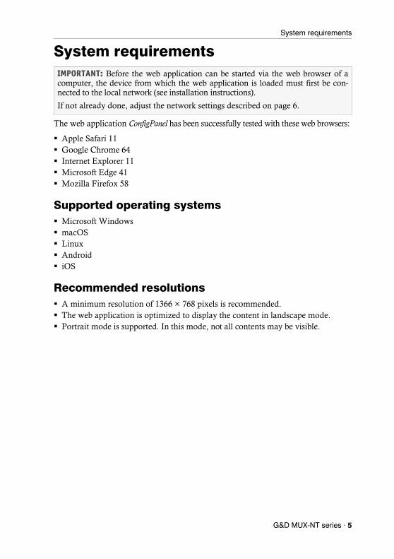
System requirements
The web application ConfigPanel has been successfully tested with these web browsers:
Apple Safari 11 Google Chrome 64 Internet Explorer 11 Microsoft Edge 41 Mozilla Firefox 58
Supported operating systems Microsoft Windows macOS Linux Android iOS
Recommended resolutions A minimum resolution of 1366 × 768 pixels is recommended. The web application is optimized to display the content in landscape mode. Portrait mode is supported. In this mode, not all contents may be visible.
IMPORTANT: Before the web application can be started via the web browser of a computer, the device from which the web application is loaded must first be con-nected to the local network (see installation instructions).
If not already done, adjust the network settings described on page 6.
G&D MUX-NT series · 5

Initial configuration of the network settings
Initial configuration of the network settings
To access the web application, the network settings of the device on which the web application is operated need to be configured.
How to configure the network settings before integrating the device into the local network:
1. Use a category 5 (or better) twisted pair cable to connect the network interface of any computer to the device’s Network A interface.
2. Ensure that the IP address of the computer’s network interface is part of the sub-net to which the device’s IP address belongs to.
3. Switch on the device.
4. Start the computer’s web browser and enter 192.168.0.1 in the address bar.
5. Configure the network interface(s) and the global network settings as described in the paragraph Network settings on page 16 f.
6. Remove the twisted pair cable connection between computer and device.
7. Implement the device in the local network.
NOTE: In the defaults, the following settings are pre-selected:
IP address of network interface A: 192.168.0.1 IP address of network interface B: address obtained using DHCP global network settings: settings obtained using DHCP
NOTE: Use the IP address 192.168.0.100, for example.
IMPORTANT: It is not possible to operate both network interfaces within one subnet!
6 · G&D MUX-NT series
Getting started
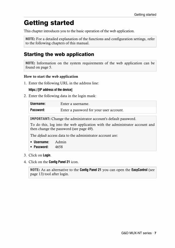
Getting startedThis chapter introduces you to the basic operation of the web application.
Starting the web application
How to start the web application
1. Enter the following URL in the address line:
https://[IP address of the device]
2. Enter the following data in the login mask:
3. Click on Login.
4. Click on the Config Panel 21 icon.
NOTE: For a detailed explanation of the functions and configuration settings, refer to the following chapters of this manual.
NOTE: Information on the system requirements of the web application can be found on page 5.
Username: Enter a username.
Password: Enter a password for your user account.
IMPORTANT: Change the administrator account's default password.
To do this, log into the web application with the administrator account and then change the password (see page 49).
The default access data to the administrator account are:
Username: Admin Password: 4658
NOTE: As an alternative to the Config Panel 21 you can open the EasyControl (see page 13) tool after login.
G&D MUX-NT series · 7

Getting started
Operating the web application
User interface
The user interface of the web application consists of several areas:
The different areas of the user interface serve different tasks. The following table lists the purpose of each area:
Figure 1: User interface of the web application
Menu : In the menu the different functions of the web application are summarised in various topics.
Breadcrumb navigation :
The breadcrumb navigation shows you the path to the cur-rently opened dialog.
To quickly return to a higher-level dialog, you can click on it in the breadcrumb navigation.
Filter function : You can use the filter function to narrow down the items displayed in the main view.
In the text box, enter part of the name of the element you want to find. Only elements that contain this text in one of the displayed columns are displayed in the main view. The names are not case-sensitive during filtering.
To delete the filter, click on the [X] icon.
Main view : After selecting a topic in the menu, the contents of this topic are displayed here.
8 · G&D MUX-NT series

Getting started
Shortcuts : Language selection: The country flag shows the language currently active in the web application.
Click on the country flag to switch between languages (Ger-man/English). A submenu opens displaying all supported languages in the form of flags. Switch the language by clicking on the desired flag.
User: A click on the user icon opens a submenu:
The name of the active user is displayed in the submenu. Click on User to access the user settings of the active user. Click on Logout to exit the active session.
Monitoring status: This icon shows you at a glance whether all monitoring values are within the normal range (green icon) or if at least one monitoring value is outside the nor-mal range (yellow or red icon).
The Monitoring status icon always takes the colour of the most critical monitoring value
If the icon is displayed in yellow or red, you can access the Active alarms dialog by clicking on the icon.
Buttons : Depending on the dialog shown, different buttons are dis-played in this area.
G&D MUX-NT series · 9
Getting started
Frequently used buttons
The user interface uses various buttons to perform operations. The following table informs you about the names and functions of the buttons used in many dialog masks:
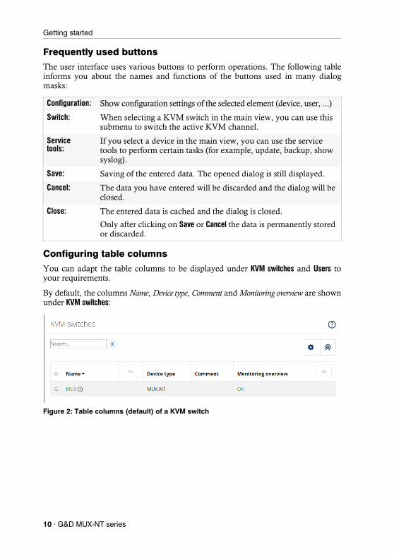
Configuring table columns
You can adapt the table columns to be displayed under KVM switches and Users to your requirements.
By default, the columns Name, Device type, Comment and Monitoring overview are shown under KVM switches:
Configuration: Show configuration settings of the selected element (device, user, ...)
Switch: When selecting a KVM switch in the main view, you can use this submenu to switch the active KVM channel.
Service tools:
If you select a device in the main view, you can use the service tools to perform certain tasks (for example, update, backup, show syslog).
Save: Saving of the entered data. The opened dialog is still displayed.
Cancel: The data you have entered will be discarded and the dialog will be closed.
Close: The entered data is cached and the dialog is closed.
Only after clicking on Save or Cancel the data is permanently stored or discarded.
Figure 2: Table columns (default) of a KVM switch
10 · G&D MUX-NT series

Getting started
How to change the columns to be displayed:
1. Click on the gears icon ( ) above the table.
2. To add a column, select it from the Columns drop-down box and click on Add column.
3. To delete a column, click on the red button ( ) below the column header.
4. Click on the green check mark ( ) to save your settings or klick on the red Discard button ( ).
How to change the column order:
1. Click on the gears icon above the table.
2. To move a column to the left, click on the arrow left icon ( ) of this column.
3. To move a column to the right, click on the arrow right icon ( ) of this column.
4. Click on the green check mark ( ) to save your settings or click on the red Discard button ( ).
How to reset the table configuration to the default settings
1. Click on the Table configuration reset icon ( ) above the table.
2. Confirm the security prompt by clicking on Yes.
NOTE: The Name column is always shown as the first column of the table.
Figure 3: Table configuration
NOTE: The Name column is always shown as the first column of the table.
G&D MUX-NT series · 11
Getting started
Selecting the language of the web application
How to change the default language of the web application:
1. Click on the country flag at the top right.
A submenu opens displaying all supported languages in the form of flags.
2. Change the language by clicking on the desired flag.
Closing the web applicationUse the Close button to end the active session of the web application.
How to close the web application:
1. Click on the user icon at the top right.
2. Click on Logout to exit the active session.
Showing the version number of the web application
How to show the version number of the web application:
1. In the menu, click on Information.
2. The General tab provides you with information about the ConfigPanel version.
NOTE: The selected language is saved in the user settings of the active user. The next time this user logs on, the previously selected language setting is applied.
IMPORTANT: To protect the web application against unauthorised access, always use the Logout function after finishing your work with the web application.
12 · G&D MUX-NT series
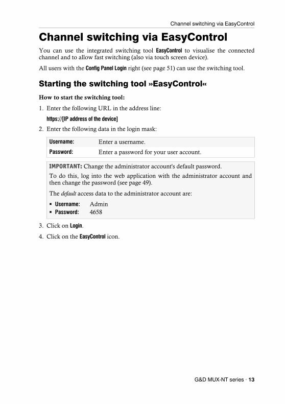
Channel switching via EasyControl
Channel switching via EasyControlYou can use the integrated switching tool EasyControl to visualise the connected channel and to allow fast switching (also via touch screen device).
All users with the Config Panel Login right (see page 51) can use the switching tool.
Starting the switching tool »EasyControl«
How to start the switching tool:
1. Enter the following URL in the address line:
https://[IP address of the device]
2. Enter the following data in the login mask:
3. Click on Login.
4. Click on the EasyControl icon.
Username: Enter a username.
Password: Enter a password for your user account.
IMPORTANT: Change the administrator account's default password.
To do this, log into the web application with the administrator account and then change the password (see page 49).
The default access data to the administrator account are:
Username: Admin Password: 4658
G&D MUX-NT series · 13

Channel switching via EasyControl
Switching the active KVM channelThe user interface consists of three buttons for switching between the three channels of the KVM switch.
When using the default colour scheme, a green frame indicates the currently active channel.
How to switch to another KVM channel:
1. Click on the button of the channel you want to switch off.
Figure 4: User interface of the »EasyControl« switching tool
14 · G&D MUX-NT series
Channel switching via EasyControl
Changing the colour scheme of the switching tool
How to change the colour scheme of the switching tool:
1. Click on the gears icon at the bottom right.
2. Click on the button of the colour scheme you want to use (Skin 1, Skin 2 or Skin 3).
3. Each colour scheme is available in a variant for light and dark working environ-ments. Select the desired variant:
4. Click the gears icon again to close the settings.
Renaming KVM channels
How to rename the KVM channels:
1. Click on the gears icon ( ) at the bottom right.
2. Edit the names in the fields Channel x.
3. Click on Save.
4. Click the gears icon again to close the settings.
Closing the »EasyControl« switching tool
How to close the switching tool:
1. Click on the Exit icon ( ) at the bottom right.
NOTE: The selected colour scheme is saved in the user settings of the active user. The next time the switching tool is used, the previously selected colour scheme is applied.
Bright: Apply variant for bright working environments
Dark: Apply variant for dark working environments
IMPORTANT: Only users with Superuser rights can edit the names of the individual KVM channels in the switching tool.
G&D MUX-NT series · 15
Basic configuration of the web application
Basic configuration of the web application
Network settingsThe device provides two network interfaces (Network A and Network B). The network interfaces lets you integrate a device into up to two separate networks.
Configuring the network interfaces
To connect the device to a local network, you need to configure the settings of the network.
How to configure the settings of a network interface:
1. In the menu, click on KVM switches.
2. Click on the device you want to configure and then click on Configuration.
3. Click on the tab Network.
4. Go to the paragraph Interfaces.
IMPORTANT: Note the separate instructions about the Initial configuration of the net-work settings on page 6.
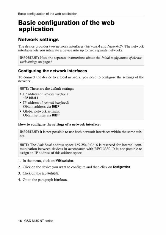
NOTE: These are the default settings:
IP address of network interface A: 192.168.0.1
IP address of network interface B: Obtain address via DHCP
Global network settings: Obtain settings via DHCP
IMPORTANT: It is not possible to use both network interfaces within the same sub-net.
NOTE: The Link Local address space 169.254.0.0/16 is reserved for internal com-munication between devices in accordance with RFC 3330. It is not possible to assign an IP address of this address space.
16 · G&D MUX-NT series
Basic configuration of the web application
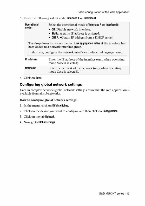
5. Enter the following values under Interface A or Interface B:
6. Click on Save.
Configuring global network settings
Even in complex networks global network settings ensure that the web application is available from all subnetworks.
How to configure global network settings:
1. In the menu, click on KVM switches.
2. Click on the device you want to configure and then click on Configuration.
3. Click on the tab Network.
4. Now go to Global settings.
Operational mode:
Select the operational mode of Interface A or Interface B:
Off: Disable network interface. Static: A static IP address is assigned. DHCP: Obtain IP address from a DHCP server:
IP address: Enter the IP address of the interface (only when operating mode Static is selected).
Netmask: Enter the netmask of the network (only when operating mode Static is selected).
The drop-down list shows the text Link aggregation active if the interface has been added to a network interface group.
In this case, configure the network interfaces under »Link aggregation«.
G&D MUX-NT series · 17

Basic configuration of the web application
5. Enter the following values:
6. Click on Save.
Increasing the reliability of network connections by link aggre-gation
By default, you can use both network interfaces at the same time to acees the web application from two different network segments, for example
To increase reliability, the entwork interfaces can be grouped via link aggregation. Within a group, only one interface is active at a time. Another interface only becomes active if the active interface fails.
Two different modes are available for monitoring the interfaces:
MII mode: The carrier status of the network interface is monitored via the media independent interface überwacht. In this mode, only the functionality of the network is tested.
ARP mode: Using the address resolution protocol, requests are sent to an ARP target on the network. The response from the ARP target confirms both the functionality of the network interface and a proper network connection to the ARP target.
If the ARP target is connected to the network but temporarily offline, the requests cannot be answered. For this reason, you should determine several ARP targets in order to obtain a response from at least one target even if an ARP target fails.
Operating mode: Select the operating mode:
Static: Use static settings. DHCP: Obtain settings from a DHCP server.
Hostname: Enter the device's hostname.
Domain: Enter the domain to which the device should belong.
Gateway: Enter the gateway's IP address.
DNS server 1: Enter the IP address of the DNS server.
DNS server 2: Optionally, enter the IP address of another DNS server.
NOTE: It is not possible to combine MII and ARP mode.
When selecting the DHCP mode, the following settings are applied auto-matically. It is not possible to enter any vlaues.
18 · G&D MUX-NT series
Basic configuration of the web application
How to configure the settings of grouped network interfaces:
1. In the menu, click on KVM switches.
2. Click on the device you want to configure and then click on Configuration.
3. Click on the tab Network.
4. Go to the paragraph Link aggregation.
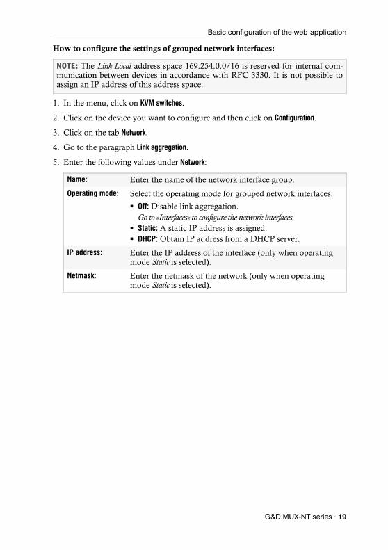
5. Enter the following values under Network:
NOTE: The Link Local address space 169.254.0.0/16 is reserved for internal com-munication between devices in accordance with RFC 3330. It is not possible to assign an IP address of this address space.
Name: Enter the name of the network interface group.
Operating mode: Select the operating mode for grouped network interfaces:
Off: Disable link aggregation.Go to »Interfaces« to configure the network interfaces.
Static: A static IP address is assigned. DHCP: Obtain IP address from a DHCP server.
IP address: Enter the IP address of the interface (only when operating mode Static is selected).
Netmask: Enter the netmask of the network (only when operating mode Static is selected).
G&D MUX-NT series · 19

Basic configuration of the web application
6. Enter the following values under Parameter:
7. Click on Save.
Primary slave: Select whether data traffic should preferably be transmitted via the interface Network A (Interface A) or the interface Network B (Interface B). As soon as the selected interface is available, this interface is used for data traffic.
If you select the option None, the data traffic is sent via any interface. A switch-over occurs only if the active interface fails.
Link monitoring: Select whether you want to use the MII or the ARP mode (see explanation above) to monitor the interface.
MII down delay: Waiting period in milliseconds before a failed network inter-face is disabled.
The entered value must be a multiple of 100 ms (the MII link monitoring frequency).
MII up delay: Waiting period in milliseconds before a reset network inter-face is activated.
The entered value must be a multiple of 100 ms (the MII link monitoring frequency).
ARP interval: Enter the interval (100 to 10,000 milliseconds) after which the system checks for incoming ARP packets of the network interfaces.
ARP validate: The validation ensures that the ARP packet for a particular network interface has been generated by one of the specified ARP targets.
Select whether or which of the incoming ARP packets should be validated:
None: ARP packets are not validated (default).
Active: Only the ARP packets of the active network inter-face are validated.
Backup: Only the ARP packets of the inactive network interface are validated
All: The ARP packets of all network interfaces of the group are validated.
ARP target: The table contains a list of all configured ARP targets.
Use the buttons New, Edit and Delete to manage the ARP targets.
20 · G&D MUX-NT series
Basic configuration of the web application
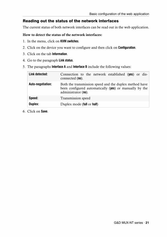
Reading out the status of the network interfaces
The current status of both network interfaces can be read out in the web application.
How to detect the status of the network interfaces:
1. In the menu, click on KVM switches.
2. Click on the device you want to configure and then click on Configuration.
3. Click on the tab Information.
4. Go to the paragraph Link status.
5. The paragraphs Interface A and Interface B include the following values:
6. Click on Save.
Link detected: Connection to the network established (yes) or dis-connected (no).
Auto-negotiation: Both the transmission speed and the duplex method have been configured automatically (yes) or manually by the administrator (no).
Speed: Transmission speed
Duplex: Duplex mode (full or half)
G&D MUX-NT series · 21

Basic configuration of the web application
Creating and administrating netfilter rulesBy default, all network computers have access to the web application ConfigPanel (open system access).
Once a netfilter rule has been created, open system access is disabled and all incom-ing data packets are compared with the netfilter rules. The list of netfilter rules is processed in the stored order. As soon as a rule applies, the corresponding action is executed and the following rules are ignored.
Creating new netfilter rules
How to create a new netfilter rule:
1. In the menu, click on KVM switches.
2. Click on the device you want to configure and then click on Configuration.
3. Click on the tab Network.
4. Go to the paragraph Netfilter.
5. Enter the following values:
NOTE: The open system access allows unrestricted connections via ports 80/TCP (HTTP), 443/TCP (HTTPS) and 161/UDP (SNMP).
Interface: In the pull-down menu, select on which network interfaces the data packets are to be intercepted and manipulated:
All Interface A Interface B Link-Aggregation group
Option: In the pull-down menu, select how to interpret the sender information of the rule:
Normal: The rule applies to data packets whose sender information corresponds to the IP address or MAC address specified in the rule.
Inverted: The rule applies to data packets whose sender information does not correspond to the IP address or MAC address specified in the rule.
22 · G&D MUX-NT series
Basic configuration of the web application
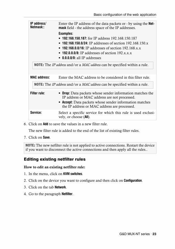
6. Click on Add to save the values in a new filter rule.
The new filter rule is added to the end of the list of existing filter rules.
7. Click on Save.
Editing existing netfilter rules
How to edit an existing netfilter rule:
1. In the menu, click on KVM switches.
2. Click on the device you want to configure and then click on Configuration.
3. Click on the tab Network.
4. Go to the paragraph Netfilter.
IP address/ Netmask::
Enter the IP address of the data packets or - by using the Net-mask field - the address space of the IP addresses.
Examples: 192.168.150.187: for IP address 192.168.150.187 192.168.150.0/24: IP addresses of section 192.168.150.x 192.168.0.0/16: IP addresses of section 192.168.x.x 192.0.0.0/8: IP addresses of section 192.x.x.x 0.0.0.0/0: all IP addresses
MAC address: Enter the MAC address to be considered in this filter rule.
Filter rule: Drop: Data packets whose sender information matches the IP address or MAC address are not processed.
Accept: Data packets whose sender information matches the IP address or MAC address are processed.
Service: Select a specific service for which this rule is used exclusi-vely, or choose (All).
NOTE: The new nefilter rule is not applied to active connections. Restart the device if you want to disconnect the active connections and then apply all the rules..
NOTE: The IP address and/or a MAC address can be specified within a rule.
NOTE: The IP address and/or a MAC address can be specified within a rule.
G&D MUX-NT series · 23
Basic configuration of the web application
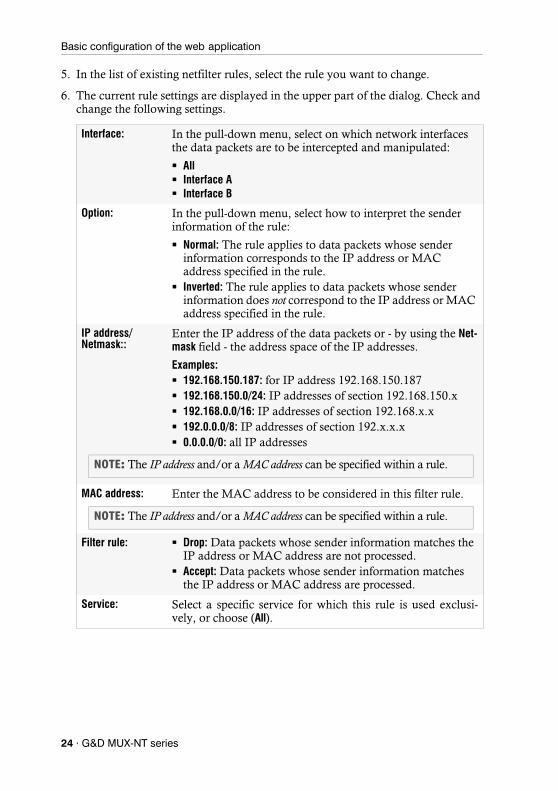
5. In the list of existing netfilter rules, select the rule you want to change.
6. The current rule settings are displayed in the upper part of the dialog. Check and change the following settings.
Interface: In the pull-down menu, select on which network interfaces the data packets are to be intercepted and manipulated:
All Interface A Interface B
Option: In the pull-down menu, select how to interpret the sender information of the rule:
Normal: The rule applies to data packets whose sender information corresponds to the IP address or MAC address specified in the rule.
Inverted: The rule applies to data packets whose sender information does not correspond to the IP address or MAC address specified in the rule.
IP address/ Netmask::
Enter the IP address of the data packets or - by using the Net-mask field - the address space of the IP addresses.
Examples: 192.168.150.187: for IP address 192.168.150.187 192.168.150.0/24: IP addresses of section 192.168.150.x 192.168.0.0/16: IP addresses of section 192.168.x.x 192.0.0.0/8: IP addresses of section 192.x.x.x 0.0.0.0/0: all IP addresses
MAC address: Enter the MAC address to be considered in this filter rule.
Filter rule: Drop: Data packets whose sender information matches the IP address or MAC address are not processed.
Accept: Data packets whose sender information matches the IP address or MAC address are processed.
Service: Select a specific service for which this rule is used exclusi-vely, or choose (All).
NOTE: The IP address and/or a MAC address can be specified within a rule.
NOTE: The IP address and/or a MAC address can be specified within a rule.
24 · G&D MUX-NT series

Basic configuration of the web application
7. Click on Apply to save your settings.
8. Click on Save.
Deleting existing netfilter rules
How to delete existing netfilter rules:
1. In the menu, click on KVM switches.
2. Click on the device you want to configure and then click on Configuration.
3. Click on the tab Network.
4. Go to the paragraph Netfilter.
5. In the list of existing netfilter rules, select the rule you want to delete.
6. Click on Delete.
7. Confirm the confirmation prompt by clicking on Yes or cancel the process by clicking on No.
8. Click on Save.
Changing the order or priority of existing netfilter rules
The list of netfilter rules is processed in the stored order. As soon as a rule applies, the corresponding action is executed and the following rules are ignored.
How to change the order or priority of existing netfilter rules:
1. In the menu, click on KVM switches.
2. Click on the device you want to configure and then click on Configuration.
3. Click on the tab Network.
4. Go to the paragraph Netfilter.
5. In the list of existing netfilter rules, select the rule whose order/priority you want to change.
6. Click the button Arrow up to increase the priority or the button Arrow down to decrease the priority.
7. Click on Save.
NOTE: The new nefilter rule is not applied to active connections. Restart the device if you want to disconnect the active connections and then apply all the rules..
IMPORTANT: Pay attention to the order or priority of the individual rules, espe-cially when adding new rules.
G&D MUX-NT series · 25
Basic configuration of the web application
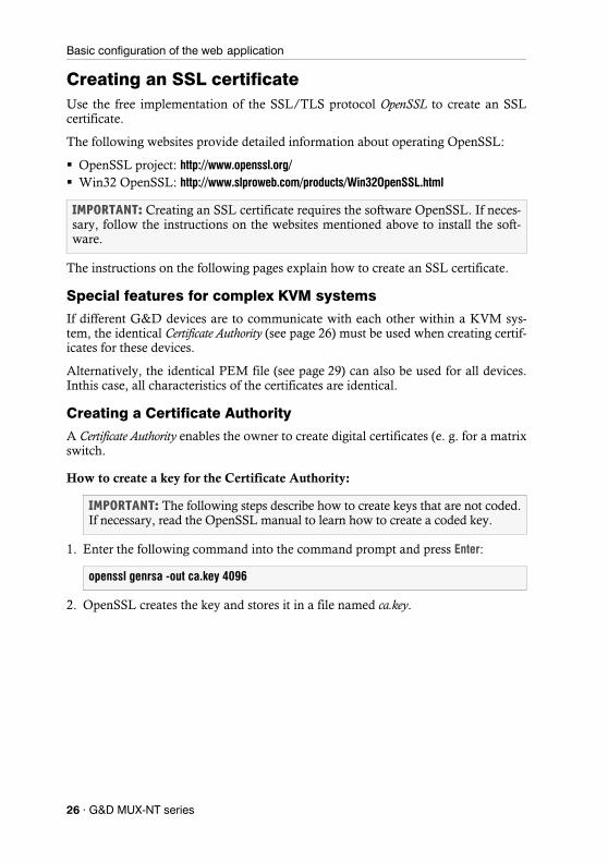
Creating an SSL certificateUse the free implementation of the SSL/TLS protocol OpenSSL to create an SSL certificate.
The following websites provide detailed information about operating OpenSSL:
OpenSSL project: http://www.openssl.org/ Win32 OpenSSL: http://www.slproweb.com/products/Win32OpenSSL.html
The instructions on the following pages explain how to create an SSL certificate.
Special features for complex KVM systems
If different G&D devices are to communicate with each other within a KVM sys-tem, the identical Certificate Authority (see page 26) must be used when creating certif-icates for these devices.
Alternatively, the identical PEM file (see page 29) can also be used for all devices. Inthis case, all characteristics of the certificates are identical.
Creating a Certificate Authority
A Certificate Authority enables the owner to create digital certificates (e. g. for a matrix switch.
How to create a key for the Certificate Authority:
1. Enter the following command into the command prompt and press Enter:
2. OpenSSL creates the key and stores it in a file named ca.key.
IMPORTANT: Creating an SSL certificate requires the software OpenSSL. If neces-sary, follow the instructions on the websites mentioned above to install the soft-ware.
IMPORTANT: The following steps describe how to create keys that are not coded. If necessary, read the OpenSSL manual to learn how to create a coded key.
openssl genrsa -out ca.key 4096
26 · G&D MUX-NT series

Basic configuration of the web application
How to create the Certificate Authority:
1. Enter the following command into the command prompt and press Enter:
2. Now, OpenSSL queries the data to be integrated into the certificate.
The following table shows the different fields and an exemplary entry:
Enter the data you want to state, and confirm each entry by pressing Enter.
3. OpenSSL creates the key and stores it in a file named ca.crt.
openssl req -new -x509 -days 3650 -key ca.key -out ca.crt
Field Example
Country Name (2 letter code) DE
State or Province Name NRW
Locality Name (e.g., city) Siegen
Organization Name (e.g., company) Guntermann & Drunck GmbH
Organizational Unit Name (e.g., section)
Common Name (e.g., YOUR name) Guntermann & Drunck GmbH
Email Address
IMPORTANT: The device's IP address must not be entered under Common Name.
IMPORTANT: Distribute the certificate ca.crt to the web browsers using the web application. The certificate checks the validity and the trust of the certificate stored in the device.
G&D MUX-NT series · 27

Basic configuration of the web application
Creating any certificate
How to create a key for the certificate to be created:
1. Enter the following command into the command prompt and press Enter:
2. OpenSSL creates the key and stores it in a file named server.key.
How to create the certificate request:
1. Enter the following command into the command prompt and press Enter:
2. Now, OpenSSL queries the data to be integrated into the certificate.
The following table shows the different fields and an exemplary entry:
Enter the data you want to state, and confirm each entry by pressing Enter.
3. If desired, the Challenge Password can be defined. This password is needed if you have lost the secret key and the certificate needs to be recalled.
4. Now, the certificate is created and stored in a file named server.csr.
IMPORTANT: The following steps describe how to create keys that are not coded. If necessary, read the OpenSSL manual to learn how to create a coded key.
openssl genrsa -out server.key 4096
openssl req -new -key server.key -out server.csr
Feld Beispiel
Country Name (2 letter code) DE
State or Province Name NRW
Locality Name (e.g., city) Siegen
Organization Name (e.g., company) Guntermann & Drunck GmbH
Organizational Unit Name (e.g., section)
Common Name (e.g., YOUR name) 192.168.0.10
Email Address
IMPORTANT: Enter the IP address of the device on which the certificate is to be installed into the row Common Name.
28 · G&D MUX-NT series

Basic configuration of the web application
Creating and signing an X509 certificate
1. Enter the following command into the command prompt and press Enter:
2. OpenSSL creates the certificate and stores it in a file named server.crt.
Creating a PEM file
1. Enter the following command(s) into the prompt and press Enter:
a. Linux
b. Windows
2. The gdcd.pem file is created while copying. It contains the created certificate and its key as well as the Certificate Authority.
Selecting an SSL certificateBy default, each G&D device with integrated web application stores at least one SSL certificate. The certificate has two functions:
The connection between web browser and web application can be established via an SSL-secured connection. In this case, the SSL certificate allows the user to authenticate the opposite side.If the device’s IP address does not match the IP address stored in the certificate, the web browser sends a warning message.
openssl x509 -req -days 3650 -in server.csr -CA ca.crt -CAkey ca.key -set_serial 01 -out server.crt
NOTE: The .pem file contains the following three components:
server certificate private server key certificate of the certification authority
If these three components are available separately, enter them successively to the Clear text entry before updating the certificate stored in the device.
cat server.crt > gdcd.pemcat server.key >> gdcd.pemcat ca.crt >> gdcd.pem
copy server.crt + server.key + ca.crt gdcd.pem
ADVICE: You can import a user certificate so that the device’s IP address matches the IP address stored in the certificate.
G&D MUX-NT series · 29
Basic configuration of the web application
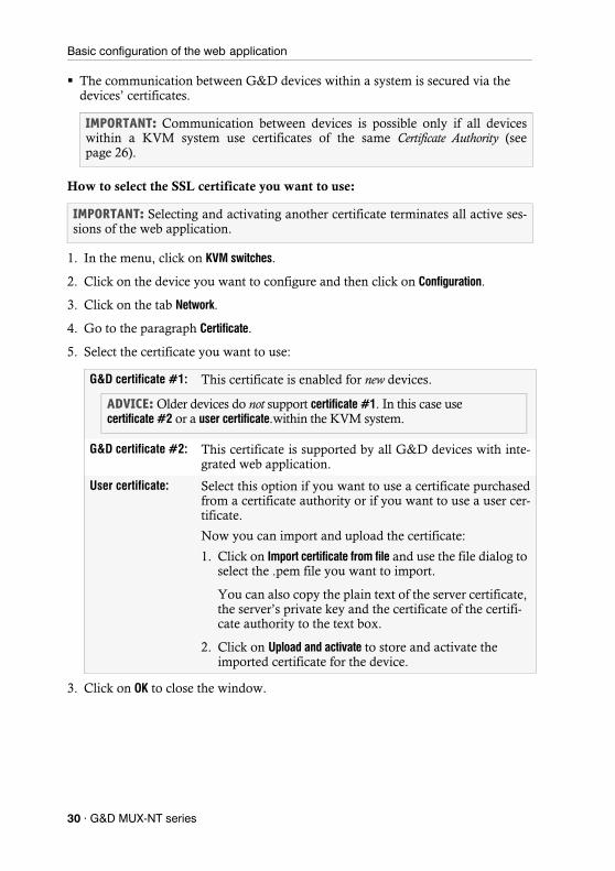
The communication between G&D devices within a system is secured via the devices’ certificates.
How to select the SSL certificate you want to use:
1. In the menu, click on KVM switches.
2. Click on the device you want to configure and then click on Configuration.
3. Click on the tab Network.
4. Go to the paragraph Certificate.
5. Select the certificate you want to use:
3. Click on OK to close the window.
IMPORTANT: Communication between devices is possible only if all devices within a KVM system use certificates of the same Certificate Authority (see page 26).
IMPORTANT: Selecting and activating another certificate terminates all active ses-sions of the web application.
G&D certificate #1: This certificate is enabled for new devices.
G&D certificate #2: This certificate is supported by all G&D devices with inte-grated web application.
User certificate: Select this option if you want to use a certificate purchased from a certificate authority or if you want to use a user cer-tificate.
Now you can import and upload the certificate:
1. Click on Import certificate from file and use the file dialog to select the .pem file you want to import.
You can also copy the plain text of the server certificate, the server’s private key and the certificate of the certifi-cate authority to the text box.
2. Click on Upload and activate to store and activate the imported certificate for the device.
ADVICE: Older devices do not support certificate #1. In this case use certificate #2 or a user certificate.within the KVM system.
30 · G&D MUX-NT series
Basic configuration of the web application
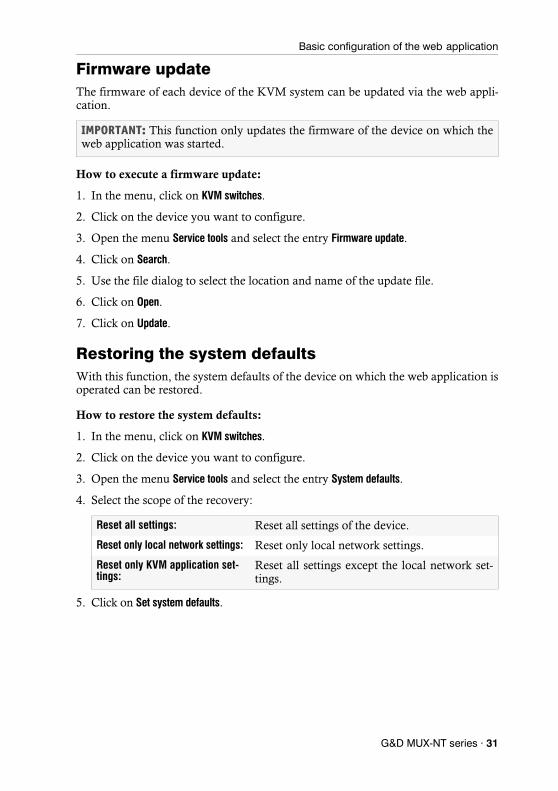
Firmware updateThe firmware of each device of the KVM system can be updated via the web appli-cation.
How to execute a firmware update:
1. In the menu, click on KVM switches.
2. Click on the device you want to configure.
3. Open the menu Service tools and select the entry Firmware update.
4. Click on Search.
5. Use the file dialog to select the location and name of the update file.
6. Click on Open.
7. Click on Update.
Restoring the system defaultsWith this function, the system defaults of the device on which the web application is operated can be restored.
How to restore the system defaults:
1. In the menu, click on KVM switches.
2. Click on the device you want to configure.
3. Open the menu Service tools and select the entry System defaults.
4. Select the scope of the recovery:
5. Click on Set system defaults.
IMPORTANT: This function only updates the firmware of the device on which the web application was started.
Reset all settings: Reset all settings of the device.
Reset only local network settings: Reset only local network settings.
Reset only KVM application set-tings:
Reset all settings except the local network set-tings.
G&D MUX-NT series · 31

Basic configuration of the web application
Restarting the KVM switchThis function restarts the KVM switch. Before restarting, you will be prompted for confirmation to prevent an accidental restart.
How to restart the KVM switch using the web application:
1. In the menu, click on KVM switches.
2. Click on the desired device.
3. Open the menu Service tools and select the entry Restart.
4. Confirm the confirmation prompt with Yes.
32 · G&D MUX-NT series
Network functions of the devices
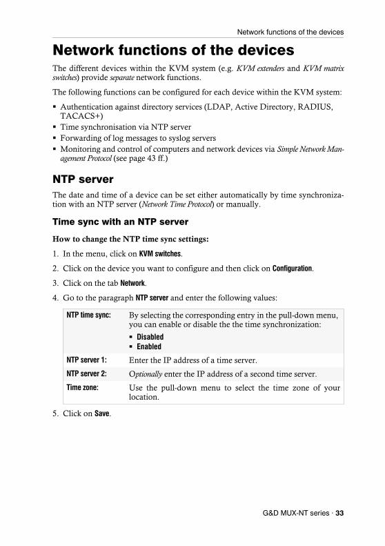
Network functions of the devicesThe different devices within the KVM system (e.g. KVM extenders and KVM matrix switches) provide separate network functions.
The following functions can be configured for each device within the KVM system:
Authentication against directory services (LDAP, Active Directory, RADIUS, TACACS+)
Time synchronisation via NTP server Forwarding of log messages to syslog servers Monitoring and control of computers and network devices via Simple Network Man-
agement Protocol (see page 43 ff.)
NTP serverThe date and time of a device can be set either automatically by time synchroniza-tion with an NTP server (Network Time Protocol) or manually.
Time sync with an NTP server
How to change the NTP time sync settings:
1. In the menu, click on KVM switches.
2. Click on the device you want to configure and then click on Configuration.
3. Click on the tab Network.
4. Go to the paragraph NTP server and enter the following values:
5. Click on Save.
NTP time sync: By selecting the corresponding entry in the pull-down menu, you can enable or disable the the time synchronization:
Disabled Enabled
NTP server 1: Enter the IP address of a time server.
NTP server 2: Optionally enter the IP address of a second time server.
Time zone: Use the pull-down menu to select the time zone of your location.
G&D MUX-NT series · 33
Network functions of the devices
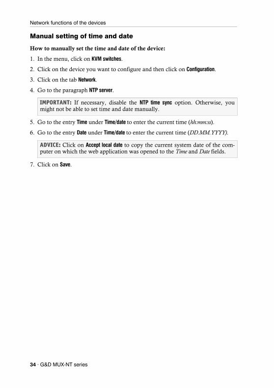
Manual setting of time and date
How to manually set the time and date of the device:
1. In the menu, click on KVM switches.
2. Click on the device you want to configure and then click on Configuration.
3. Click on the tab Network.
4. Go to the paragraph NTP server.
5. Go to the entry Time under Time/date to enter the current time (hh:mm:ss).
6. Go to the entry Date under Time/date to enter the current time (DD.MM.YYYY).
7. Click on Save.
IMPORTANT: If necessary, disable the NTP time sync option. Otherwise, you might not be able to set time and date manually.
ADVICE: Click on Accept local date to copy the current system date of the com-puter on which the web application was opened to the Time and Date fields.
34 · G&D MUX-NT series
Network functions of the devices
Logging syslog messagesThe syslog protocol is used to transmit log messages in networks. The log messages are transmitted to a syslog server that logs the log messages of many devices in the computer network.
Among other things, eight different severity codes have been defined to classify the log messages:
The web application enables you to configure whether the syslog messages are to be locally logged or sent to up to two syslog servers.
Local logging of syslog messages
How to locally log syslog messages:
1. In the menu, click on KVM switches.
2. Click on the device you want to configure and then click on Configuration.
3. Click on the tab Network.
4. Go to the paragraph Syslog enter the following data under Syslog local:
5. Click on Save.
0: Emergency 1: Alert 2: Critical
3: Error 4: Warning 5: Note
6: Info 7: Debug
Syslog local: By selecting the corresponding entry in the pull-down menu, you can enable or disable the local logging of syslog messa-ges:
Disabled Enabled
Log level: In this pull-down menu, select the severity from which a log message is to be logged.
The selected severity and all lower severity levels are logged.
If you select the severity 2 - Critical, messages for this code as well as for the severity levels 1 - Alert and 0 - Emergency are logged.
G&D MUX-NT series · 35

Network functions of the devices
Sending syslog messages to a server
How to send syslog messages to a server:
1. In the menu, click on KVM switches.
2. Click on the device you want to configure and then click on Configuration.
3. Click on the tab Network.
4. Go to the paragraph Syslog and enter the following values under Syslog server 1 or Syslog server 2:
5. Click on Save.
Syslog server: By selecting the corresponding entry in the pull-down menu, you can enable or disable the sending of syslog messages to a server:
Disabled Enabled
Log level: In this pull-down menu, select the severity level from which a log message is to be logged.
The selected severity level and all lower severity levels are logged.
IP address/ DNS name:
Enter the IP address or name of the server to which the syslog messages are to be sent.
Port: Enter the port - usually 514 - on which the syslog server accepts incoming messages.
Protocol: Select the protocol - usually UDP - on which the syslog server accepts incoming messages:
TCP UDP
If you select the severity 2 - Critical, messages for this code as well as for the severity levels 1 - Alert and 0 - Emergency are logged.
36 · G&D MUX-NT series

Network functions of the devices
Viewing and saving local syslog messages
If the function to log the local syslog messages is activated, these syslog messages can be viewed and, if necessary, stored in the information dailog.
How to view and store local syslog messages:
1. In the menu, click on KVM switches.
2. Click on the device you want to configure.
3. Open the menu Service untility and select the entry Syslog.
4. Click on Fetch syslog.
The local syslog messages are now retrieved and displayed in the text field.
5. Click on the red [X] to close the window.
User authentication with directory servicesIn internal corporate networks, user accounts are often managed centrally by a directory service. The device can access such a directory service and authenticate users against the directory service.
The directory service is used exclusively to authenticate a user. Rights are granted by the database of the KVM system. The following paragraphs describe the different scenarios:
The user account exists in the directory service and in the KVM systemThe user can log on with the password stored in the directory service. After a suc-cessful login, the rights of the account with the same name are assigned to the user in the KVM system.
ADVICE: Click on Save syslog to save the messages in a text file.
NOTE: If the directory service fails to authenticate the user account Admin , the user account is authenticated against the database of the device.
NOTE: The password with which the user has successfully logged on is trans-ferred to the database of the KVM system.
G&D MUX-NT series · 37

Network functions of the devices
The user account exists in the directory service, but not in the KVM systemA user who has been successfully authenticated against the directory service but does not have an account of the same name in the KVM system's database will be granted the rights of a RemoteAuth user.If required, change the rights of this particular user account to set the rights for users without a user account.
The user account exists in the KVM system, but not in the directory serviceIf the directory service is available, it reports that the user account does not exist. Access to the KVM system is denied to the user.If the server is not available but the fallback mechanism (see page 37) is activated, the user can log on with the password stored in the KVM system.
How to configure the authentication of user accounts:
1. In the menu, click on KVM switches.
2. Click on the device you want to configure and then click on Configuration.
3. Click on the tab Network.
4. Go to the paragraph Authentication.
ADVICE: Deactivate the RemoteAuth user to prevent users without user accounts to log on to the KVM system.
IMPORTANT: In order to prevent the logon of a user locked or deactivated in the directory service when the connection to the directory service fails, please observe the following security rules:
If a user account is deactivated or deleted in the directory service, this action must also be carried out in the user database of the KVM system!
Activate the fallback mechanism only in exceptional cases.
NOTE: If no directory service is used, the user accounts are managed by the device.
38 · G&D MUX-NT series
Network functions of the devices
5. Enter the following values under Authentication server:
6. Click on Save.
Auth. Server: Select the Local option if the user administration is to be car-ried out by the KVM system.
If you want to use a certain directory service, select the corre-sponding entry from the pull-down menu:
LDAP Active Directory Radius TACACS+
Fallback: Activate this option if you want to use the local user admini-stration of the KVM system if the directory service is tempo-rarily unavailable.
ADVICE: After selecting a directory service, enter the settings of the direc-tory service server in the Server Settings section of the dialog box.
IMPORTANT: In order to prevent the logon of a user locked or deactivated in the directory service when the connection to the directory service fails, please observe the following security rules:
If a user account is deactivated or deleted in the directory service, this action must also be carried out in the user database of the KVM system!
Activate the fallback mechanism only in exceptional cases.
G&D MUX-NT series · 39

Monitoring functions
Monitoring functionsUnder KVM extender and System monitoring you can view the monitoring values of any devices connected to the KVM system.
The following exemplary figure shows the monitoring values Status, Main power and Temperature of a KVM switch:
The values configured for the table view (see Configuring table columns on page 10) are listed in the table.
You can see immediately from the colour whether the status is correct (green) or criti-cal (red). The text displayed in the column also provides information about the current status.
Viewing all monitoring valuesYou can see the list of all monitoring values under KVM switches.
How to show a list of all monitoring values:
1. In the menu, click on KVM switches.
2. Click on the KVM switch you want to configure and then click on Configuration.
3. Click on the tab Monitoring.
The displayed table contains a list of all available monitoring values.
4. Click on Save.
Figure 5: Detailed view of an exemplary monitoring table
40 · G&D MUX-NT series

Monitoring functions
Enabling/disabling monitoring values
You can switch each monitoring value on and off separately or you can switch all monitoring values on or off together.
Deactivated monitoring values are not displayed in the web application.
How to enable/disable an individual monitoring value:
1. In the menu, click on KVM switches.
2. Click on the KVM switch you want to configure and then click on Configuration.
3. Click on the tab Monitoring.
4. Turn the slider in the column Enabled of the desired monitoring value to the right (enabled) or to the left (disabled).
5. Click on Save.
How to enable/disable all monitoring values:
1. In the menu, click on KVM switches.
2. Click on the KVM switch you want to configure and then click on Configuration.
3. Click on the tab Monitoring.
4. Mark or unmark the Enabled checkbox in the column header to switch all values on or off.
5. Click on Save.
IMPORTANT: The web application does not give any warnings about deactivated monitoring values and does also not send any SNMP traps for these values.
G&D MUX-NT series · 41
Monitoring functions
Advanced features for managing critical devicesThe Monitoring status icon (see User interface on page 8) shows you at a glance whether all monitoring values are within the normal range (green icon) or if at least one monitoring value is outside the normal range (yellow or red icon).
The Monitoring status icon always takes the colour of the most critical monitoring value
Displaying the list of critical monitoring values
If the Monitoring status icon is displayed in yellow or red, you can access the Active alarms dialog by clicking on the icon.
The Active alarms dialog shows any critical values.
Acknowledging the alarm of a critical device
Many alarm messages require immediate action by the administrator. Other alarms (for example, the failure of the redundant power supply), on the other hand, indicate possibly uncritical circumstances.
In such a case, you can acknowledge the alarm message of a value. The value is thus downgraded from Alarm (red) to Warning (yellow).
How to acknowledge the monitoring message of a device:
1. Click on the red Monitoring status icon at the top right.
2. Select the alarm you want to acknowledge.
3. Click on Acknowledge.
42 · G&D MUX-NT series
Monitoring devices via SNMP
Monitoring devices via SNMPThe Simple Network Management Protocol (SNMP) is used to monitor and control com-puters and network devices.
Practical use of the SNMP protocolA Network Management System (NMS) is used to monitor and control computers and network devices. The system queries and collects data from the agents of the moni-tored devices.
If an agent detects a serious event on the device, it can automatically send a trappacket to the Network Management System. This ensures that the administrator is informed about the event at short notice.
Configuring an SNMP agent
How to configure an SNMP agent:
1. In the menu, click on KVM switches.
2. Click on the device you want to configure and then click on Configuration.
3. Click on the tab Network.
4. Go to the paragraph SNMP agent.
5. Enter the followng values under Global:
NOTE: An agent is a program that runs on the monitored device and determines its status. The determined data is transmitted to the Network Management System via SNMP.
Status: Select the particular entry to either switch the SNMP agent off (Off) or on (Enabled).
Protocol: Select the protocol (TCP or UDP) – usually UDP – to be used to transmit the SNMP packets.
Port: Define the port – usually 161 – on which the incoming SNMP packets are to be accepted.
SysContact: Enter the admin’s contact data (e.g. direct dial or e-mail address).
SysName: Enter the device name.
SysLocation: Enter the location of the device.
G&D MUX-NT series · 43

Monitoring devices via SNMP
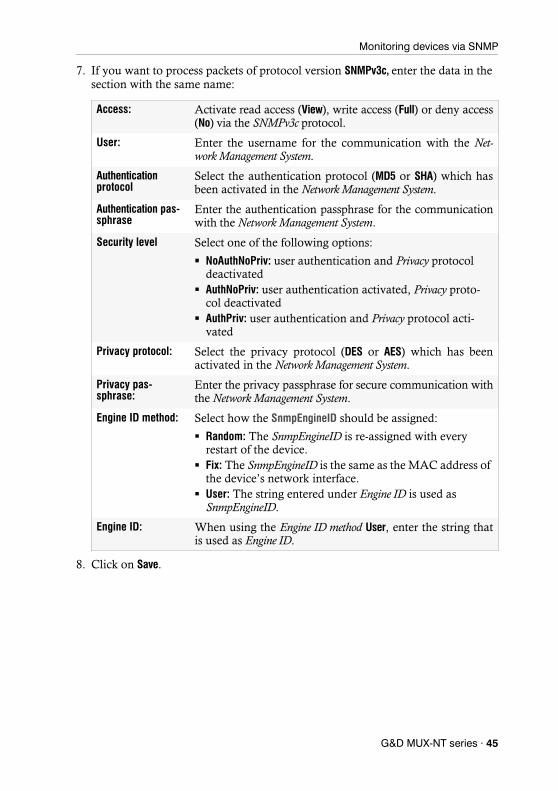
6. If you want to process packets of protocol version SNMPv2c, enter the data listed on the following page in the section with the same name.
Access: Activate read access (View), write access (Full) or deny access (No) via the SNMPv2c protocol.
Source: Enter the IP address or the address space of the addresses of incoming SNMP packets.
Examples: 192.168.150.187: Only IP address 192.168.150.187 192.168.150.0/24: IP addresses of space 192.168.150.x 192.168.0.0/16: IP addresses of space 192.168.x.x 192.0.0.0/8: IP addresses of space 192.x.x.x
Read-only community:
Enter the name of the Community which has also been selected in the Network Management System.
Write-only community:
Enter the name of the Community which has also been selected in the Network Management System.
IMPORTANT: The password (Community) of the packages of protocol version SNMPv2c is transmitted unencrypted and can therefore be easily tapped.
If necessary, use the protocol version SNMPv3 (see below) and a high security level to ensure secure data transmission.
44 · G&D MUX-NT series
Monitoring devices via SNMP
7. If you want to process packets of protocol version SNMPv3c, enter the data in the section with the same name:
8. Click on Save.
Access: Activate read access (View), write access (Full) or deny access (No) via the SNMPv3c protocol.
User: Enter the username for the communication with the Net-work Management System.
Authentication protocol
Select the authentication protocol (MD5 or SHA) which has been activated in the Network Management System.
Authentication pas-sphrase
Enter the authentication passphrase for the communication with the Network Management System.
Security level Select one of the following options:
NoAuthNoPriv: user authentication and Privacy protocol deactivated
AuthNoPriv: user authentication activated, Privacy proto-col deactivated
AuthPriv: user authentication and Privacy protocol acti-vated
Privacy protocol: Select the privacy protocol (DES or AES) which has been activated in the Network Management System.
Privacy pas-sphrase:
Enter the privacy passphrase for secure communication with the Network Management System.
Engine ID method: Select how the SnmpEngineID should be assigned:
Random: The SnmpEngineID is re-assigned with every restart of the device.
Fix: The SnmpEngineID is the same as the MAC address of the device’s network interface.
User: The string entered under Engine ID is used as SnmpEngineID.
Engine ID: When using the Engine ID method User, enter the string that is used as Engine ID.
G&D MUX-NT series · 45
Monitoring devices via SNMP
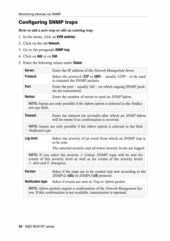
Configuring SNMP traps
How to add a new trap or edit an existing trap:
1. In the menu, click on KVM switches.
2. Click on the tab Network.
3. Go to the paragraph SNMP trap.
4. Click on Add or on Edit.
5. Enter the followng values under Global:
Server: Enter the IP address of the Network Management Server.
Protocol: Select the protocol (TCP or UDP) – usually UDP – to be used to transmit the SNMP packets.
Port: Enter the port – usually 162 – on which outgoing SNMP pack-ets are transmitted.
Retries: Enter the number of retries to send an SNMP Inform.
Timeout: Enter the timeout (in seconds) after which an SNMP Informwill be resent if no confirmation is received.
Log level: Select the severity of an event from which an SNMP trap is to be sent.
The selected severity and all lower severity levels are logged.
Version: Select if the traps are to be created and sent according to the SNMPv2c (v2c) or SNMPv3 (v3) protocol.
Notification type: Select if events are sent as Trap or Inform packet.
NOTE: Inputs are only possible if the Inform option is selected in the Notifica-tion type field.
NOTE: Inputs are only possible if the Inform option is selected in the field Notification type.
NOTE: If you select the severity 2 - Critical, SNMP traps will be sent for events of this severity level as well as for events of the severity levels 1 - Alert and 0 - Emergency.
NOTE: Inform packets require a confirmation of the Network Management Sys-tem. If this confirmation is not available, transmission is repeated.
46 · G&D MUX-NT series

Monitoring devices via SNMP
6. If you selected protocol version SNMPv2c in the last step, enter the name of the Community, which was also selected in the Network Management System.
7. If you selected protocol version SNMPv3 in step 5, enter the following data in the section with the same name:
8. Click on Save.
How to delete an existing trap:
1. In the menu, click on KVM switches.
2. Click on the tab Network.
3. Go to the paragraph SNMP trap.
4. In the row of the receiver you want to delete, click on Delete.
5. Click on Save.
IMPORTANT: The password (Community) of the packages of protocol version SNMPv2c is transmitted unencrypted and can therefore be easily tapped.
If necessary, use the protocol version SNMPv3 (see below) and a high security level to ensure secure data transmission.
User: Enter the username for the communication with the Net-work Management System.
Authentication protocol
Select the authentication protocol (MD5 or SHA) which has been activated in the Network Management System.
Authentication pas-sphrase
Enter the authentication passphrase for secure communica-tion with the Network Management System.
Security level Select one of the following options:
NoAuthNoPriv: user authentication and Privacy protocol deactivated
AuthNoPriv: user authentication activated, Privacy proto-col deactivated
AuthPriv: user authentication and Privacy protocol acti-vated
Privacy protocol: Select the privacy protocol (DES or AES) which has been activated in the Network Management System.
Privacy pas-sphrase:
Enter the privacy passphrase for secure communication with the Network Management System.
Engine ID: Enter the Engine ID of the trap receiver.
G&D MUX-NT series · 47
Users and groups
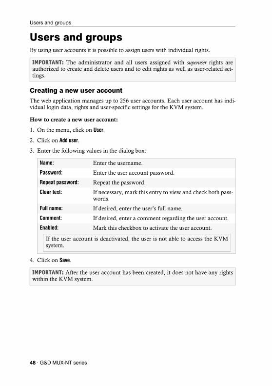
Users and groupsBy using user accounts it is possible to assign users with individual rights.
Creating a new user account
The web application manages up to 256 user accounts. Each user account has indi-vidual login data, rights and user-specific settings for the KVM system.
How to create a new user account:
1. On the menu, click on User.
2. Click on Add user.
3. Enter the following values in the dialog box:
4. Click on Save.
IMPORTANT: The administrator and all users assigned with superuser rights are authorized to create and delete users and to edit rights as well as user-related set-tings.
Name: Enter the username.
Password: Enter the user account password.
Repeat password: Repeat the password.
Clear text: If necessary, mark this entry to view and check both pass-words.
Full name: If desired, enter the user’s full name.
Comment: If desired, enter a comment regarding the user account.
Enabled: Mark this checkbox to activate the user account.
IMPORTANT: After the user account has been created, it does not have any rights within the KVM system.
If the user account is deactivated, the user is not able to access the KVM system.
48 · G&D MUX-NT series

Users and groups
Renaming a user account
How to change the name of a user account:
1. On the menu, click on Users.
2. Click on the user account you want to configure and then click on Configuration.
3. Enter the username under Name.
4. Optional: Enter the user’s full name under Full name
5. Click on Save.
Changing the password of a user account
How to change the password of a user account:
1. On the menu, click on Users.
2. Click on the user account you want to configure and then click on Configuration.
3. Change the following values in the dialog box:
4. Click on Save.
Enabling or disabling a user account
How to enable or disable a user account:
1. On the menu, click on User.
2. Click on the user account you want to configure and then click on Configuration.
3. Mark the check box Enabled to activate the user account.
If you want to block access to the system with this user account, unmark the checkbox.
4. Click on Save.
New password: Enter the new password.
Confirm password: Repeat the new password.
Clear text: Mark this entry to view and check both entered pass-words.
IMPORTANT: If a user account is disabled, the user has no access to the KVM sys-tem.
G&D MUX-NT series · 49
Users and groups
Deleting a user account
How to delete a user account:
1. On the menu, click on User.
2. Click on the user account you want to delete and then click on Delete.
3. Confirm the confirmation prompt by clicking on Yes or cancel the process by clicking on No.
System rights
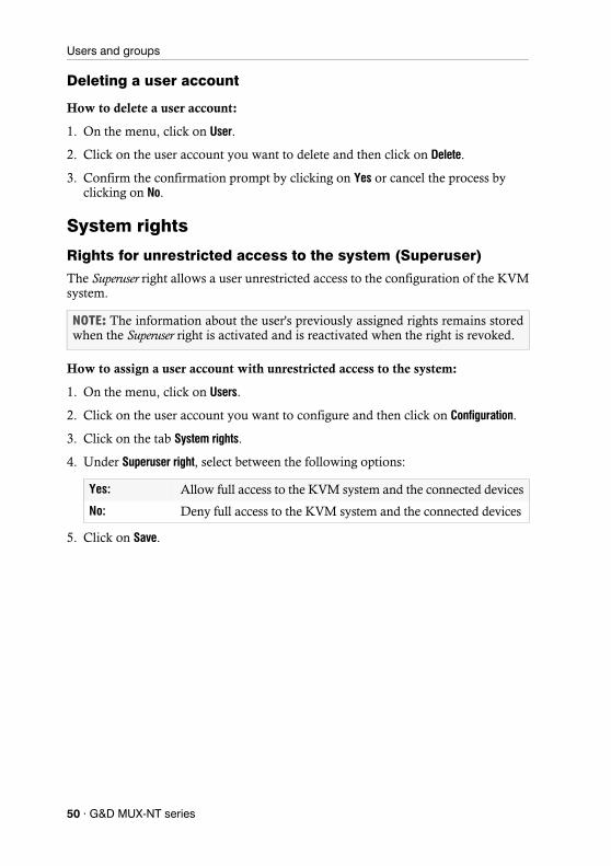
Rights for unrestricted access to the system (Superuser)
The Superuser right allows a user unrestricted access to the configuration of the KVM system.
How to assign a user account with unrestricted access to the system:
1. On the menu, click on Users.
2. Click on the user account you want to configure and then click on Configuration.
3. Click on the tab System rights.
4. Under Superuser right, select between the following options:
5. Click on Save.
NOTE: The information about the user's previously assigned rights remains stored when the Superuser right is activated and is reactivated when the right is revoked.
Yes: Allow full access to the KVM system and the connected devices
No: Deny full access to the KVM system and the connected devices
50 · G&D MUX-NT series
Users and groups
Changing the login right to the web application
How to change the login right to the web application:
1. On the menu, click on Users.
2. Click on the user account you want to configure and then click on Configuration.
3. Click on the tab System rights.
4. Under Config Panel Login, select between the following options:
5. Click on Save.
Rights to change your own password
How to change the right to change your own password:
1. On the menu, click on Users.
2. Click on the user account you want to configure and then click on Configuration.
3. Click on the tab System rights.
4. Under Change own password, select between the following options:
5. Click on OK to save your settings.
Yes: Allow access to web application
No: Deny access to web application
Yes: Allow users to change their own password
No: Deny users the right to change their own password
G&D MUX-NT series · 51
Advanced functions of the KVM system
Advanced functions of the KVM system
Temporarily (de)activating SNMP traps (Maintenance mode)By activating the maintenance mode, the user is enabled to deactivate SNMP traps (see page 46), e.g. for devices that are occupied for reasons of maintenance.
The status messages are displayed again after the maintenance mode has been deac-tivated.
(De)activating the maintenance mode
How to (de)activate a device’s maintenance mode:
1. In the menu, click on KVM switches.
2. Right-click the device and click on Maintenance > On or Maintenance > Off in the context menu.
Viewing a list of devices in maintenance mode
How to display the list of devices in maintenance mode:
1. Click on the System monitoring > Maintenance folders in the tree view.
The main view lists the respective devices.
Identifying a device by activating the Identification LEDSome devices provide an Identification LED on the front panel.
Use the web application to switch the device LEDs on or off in order to identify the devices in a rack, for example.
How to (de)activate the Identification LED of a device:
1. In the menu, click on KVM switches.
2. Right-click the device and click on Identification LED > On or Identification LED > Off in the context menu.
ADVICE: The devices in Maintenance mode are always displayed in yellow.
52 · G&D MUX-NT series

Advanced functions of the KVM system
Saving and restoring the data of the KVM systemThe backup function lets you save your configurations. You can reset your configu-rations with the restore function.
How to save the configuration of the KVM system:
1. In the directory tree, click on System > Tools.
2. Click Backup.
3. Enter the location and the name of the backup file under Path.
4. Optional: Enter a Password to secure the backup file or a Comment.
5. Select the scope of data you want to back up: You can back up either the network settings and/or the Application settings.
6. Click Backup.
How to restore the configuration of the KVM system:
1. In the directory tree, click on System > Tools.
2. Click on Restore.
3. Enter the location and the name of the backup file under Path.
4. Use the information given under Creation date and Comment to check if you selected the right backup file.
5. Select the scope of data you want to restore: You can restore either the network set-tings and/or the Application settings.
6. Click Restore.
NOTE: To save and restore your configuration, you can go to System > Tools in the directory tree or use the Tools icon.
ADVICE: Use the file button to select the name and the location of the backup file via the file dialog.
ADVICE: Use the file button to select the name and the location of the backup file via the file window.
NOTE: If one of these options cannot be selected, the data for this option was not stored.
G&D MUX-NT series · 53

In the web application's KVM Switches menu, you can configure various settings of the KVM switch and view the device's status information.
Basic configuration of KVM switches
Changing the name of a KVM switch
How to change the name of a KVM switch
1. In the menu, click on KVM switches.
2. Click on the KVM switch you want to configure and then click on Configuration.
3. Enter the desired name of the KVM switch in the Name field of the Device section.
4. Click on Save.
Changing the comment of a KVM switchThe list field of the web application displays the name of a KVM switch as well as the entered comment.
How to change the comment of a KVM switch:
1. In the menu, click on KVM switches.
2. Click on the KVM switch you want to configure and then click on Configuration.
3. Enter any comment in the Comment field of the Device section.
4. Click on Save.
ADVICE: For example, use the comment field to note the location of the KVM switch.
2 KVM switches
54 · G&D
MUX-NT series
Configuration settings of KVM switches
Deleting a KVM switch from the KVM systemIf the system is not able to find a KVM switch that has previously been integrated in the KVM system, it assumes that the device is switched off.
If a KVM switch has been permanently removed from the system, you can manually delete it from the KVM switches list.
How to delete a KVM switch that is switched off or disconnected from the system:
1. In the menu, click on KVM switches.
2. Click on the KVM switch you want to delete and then click on Delete.
3. Confirm the confirmation prompt by clicking on Yes or cancel the process by clicking on No.
Configuration settings of KVM switches
Device configuration
Changing the hotkey
The hotkey is used to switch to a computer. Press the hotkey and a select key together to switch to the corresponding computer.
If many application programs on a computer are operated with key combinations or different KVM devices are used in a cascade, the number of available key combina-tions may be limited.
If an application program or another device within the cascade uses the same hot-key, you can change the hotkey.
NOTE: Only KVM switches that have been switched off can be deleted.
NOTE: The default hotkey is set to Ctrl.
NOTE: Hotkeys can be one or a combination of the keys Ctrl, Alt, Alt Gr, Win or Shift.
G&D MUX-NT series · 55
Configuration settings of KVM switches
How to change the hotkey:
1. In the menu, click on KVM switches.
2. Click on the KVM switch you want to configure and then click on Configuration.
3. Click on the tab General.
4. In the Hotkey modifier field of the Configuration section, select at least one of the listed modifier keys by marking the corresponding check box:
5. Click on Save.
Changing a select key set
By default, the select keys 1 to 4 (set »1…4«) are active for switching between the computers connected to the KVM switch.
If one of the shortcuts resulting from the select key set collides with a key combination of an installed application program, you can change both the hotkey (see page 55) and the select key set described in this paragraph.
Ctrl
Alt
Alt Gr
Win
Shift
NOTE: If you selected multiple modifier keys, press them together to trigger the hotkey.
EXAMPLE: The default setting for switching to computer 2 is Hotkey+2 (default: Ctrl+2).
56 · G&D MUX-NT series

Configuration settings of KVM switches
How to change the select key set
1. In the menu, click on KVM switches.
2. Click on the KVM switch you want to configure and then click on Configuration.
3. Click on the tab General.
4. In the USB auto refresh field, select one of the options listed under Configuration:
5. Click on Save.
Enabling/disabling switching
Switching to a specific channel can be take place either via the buttons on the device, configured select keys, the IP-Control-API, SNMP or the web application ConfigPanel.
If required, you can restrict the options for switching between channels.
How to enable/disable the options for switching between channels:
1. In the menu, click on KVM switches.
2. Click on the KVM switch you want to configure and then click on Configuration.
1…4: Activate the select keys 1, 2, 3, 4
Num1…4: Activate the select keys Num1, Num2, Num3, Num4
A…D: Activate the select keys A, B, C, D
F1…F4: Activate the select keys F1, F2, F3, F4
NOTE: As an alternative to using select keys for switching between channels, you can use step keys to switch the channels in ascending or descending order (see separate »Installation and Operation« manual).
The active step keys depend on the selected select keys. For your information the step keys are shown behind the name of the select key set.
G&D MUX-NT series · 57
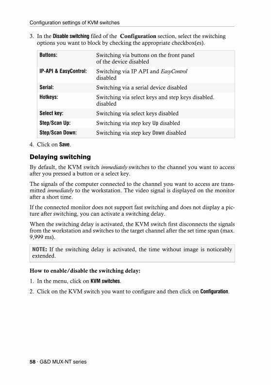
Configuration settings of KVM switches
3. In the Disable switching filed of the Configuration section, select the switching options you want to block by checking the appropriate checkbox(es).
4. Click on Save.
Delaying switching
By default, the KVM switch immediately switches to the channel you want to access after you pressed a button or a select key.
The signals of the computer connected to the channel you want to access are trans-mitted immediately to the workstation. The video signal is displayed on the monitor after a short time.
If the connected monitor does not support fast switching and does not display a pic-ture after switching, you can activate a switching delay.
When the switching delay is activated, the KVM switch first disconnects the signals from the workstation and switches to the target channel after the set time span (max. 9,999 ms).
How to enable/disable the switching delay:
1. In the menu, click on KVM switches.
2. Click on the KVM switch you want to configure and then click on Configuration.
Buttons: Switching via buttons on the front panel of the device disabled
IP-API & EasyControl: Switching via IP API and EasyControl disabled
Serial: Switching via a serial device disabled
Hotkeys: Switching via select keys and step keys disabled. disabled
Select key: Switching via select keys disabled
Step/Scan Up: Switching via step key Up disabled
Step/Scan Down: Switching via step key Down disabled
NOTE: If the switching delay is activated, the time without image is noticeably extended.
58 · G&D MUX-NT series

Configuration settings of KVM switches
3. In the Switching delay field of the Configuration section, you can adjust the delay.
4. Click on Save.
Changing the scancode sets of a PS/2 keyboard
When a key on the PS/2 keyboard is pressed, the keyboard processor sends a data packet called scancode. There are two common scancode sets (sets 2 and 3) that contain different scancodes.
By default, the KVM switch interprets all entries of a PS/2 keyboard with the scan code set 2.
How to change the setting of the scancode set:
1. In the menu, click on KVM switches.
2. Click on the KVM switch you want to configure and then click on Configuration.
3. In the Scancode set field of the Configuration section, select between the following options:
4. Click on Save.
5. Restart the KVM switch.
Reinitialising USB input devices
Once you connect a USB keyboard or mouse to the KVM switch, the input device is initialised and can be used without restrictions.
The USB connection of some USB input devices needs to be reinitialised after a cer-tain time. Activate the automatic reinitialisation of the USB input devices if a USB keyboard or mouse no longer reacts to your inputs during operation.
NOTE: Switching can be delayed up to 9,999 milliseconds. Entering the value 0 disables the delay.
ADVICE: If the pipe ("|") cannot be entered or the arrow keys of the keyboard do not work as expected, it is recommended to switch to scan code set 3.
Set 2: Activates scancode set 2 for PS/2 keyboard inputs
Set 3: Activates scancode set 3 for PS/2 keyboard inputs
NOTE: After a restart, the keyboard is initialised and the selected scancode set is applied.
G&D MUX-NT series · 59

Configuration settings of KVM switches
How to enable/disable reinitialisation of USB input devices:
1. In the menu, click on KVM switches.
2. Click on the KVM switch you want to configure and then click on Configuration.
3. In the USB auto refresh field, select one of the options listed under Configuratio:
4. Click on Save.
Channel configuration
Changing the channel name
How to change the channel name:
1. In the menu, click on KVM switches.
2. Click on the KVM switch you want to configure and then click on Configuration.
3. Click on the tab Channels.
4. Click on the channel you want to configure and then click on Configuration.
5. Enter the channel name in the Name field of the Channel section.
6. Click on Save.
Changing the comment of a channel
How to change the comment of a channel:
1. In the menu, click on KVM switches.
2. Click on the KVM switch you want to configure and then click on Configuration.
3. Click on the tab Channels.
4. Click on the channel you want to configure and then click on Configuration.
5. Enter any comment in the Comment field of the Channel section.
6. Click on Save.
Off: The connected USB input devices do not require reinitial-isation (recommended setting).
All devices: All USB devices are reinitialised regularly.
Only faulty devices: The status of the USB devices is monitored. If communi-cation to a USB device is disturbed, this device is reinitial-ised.
60 · G&D MUX-NT series
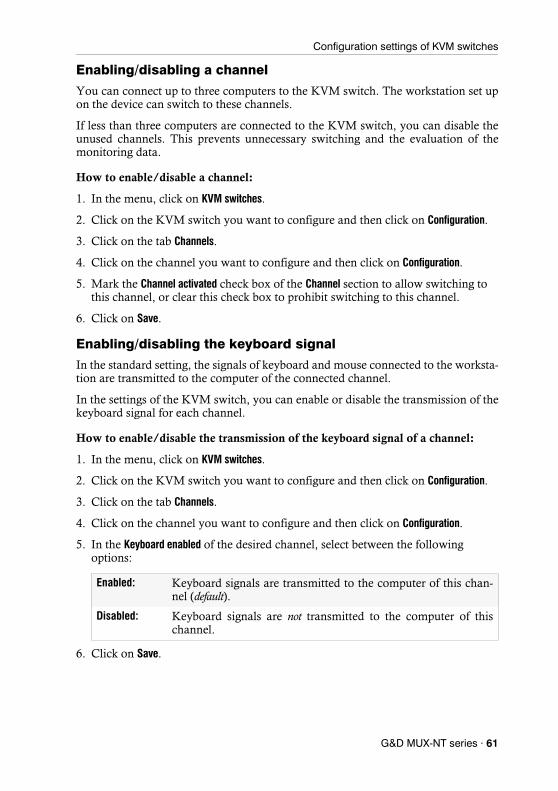
Configuration settings of KVM switches
Enabling/disabling a channel
You can connect up to three computers to the KVM switch. The workstation set up on the device can switch to these channels.
If less than three computers are connected to the KVM switch, you can disable the unused channels. This prevents unnecessary switching and the evaluation of the monitoring data.
How to enable/disable a channel:
1. In the menu, click on KVM switches.
2. Click on the KVM switch you want to configure and then click on Configuration.
3. Click on the tab Channels.
4. Click on the channel you want to configure and then click on Configuration.
5. Mark the Channel activated check box of the Channel section to allow switching to this channel, or clear this check box to prohibit switching to this channel.
6. Click on Save.
Enabling/disabling the keyboard signal
In the standard setting, the signals of keyboard and mouse connected to the worksta-tion are transmitted to the computer of the connected channel.
In the settings of the KVM switch, you can enable or disable the transmission of the keyboard signal for each channel.
How to enable/disable the transmission of the keyboard signal of a channel:
1. In the menu, click on KVM switches.
2. Click on the KVM switch you want to configure and then click on Configuration.
3. Click on the tab Channels.
4. Click on the channel you want to configure and then click on Configuration.
5. In the Keyboard enabled of the desired channel, select between the following options:
6. Click on Save.
Enabled: Keyboard signals are transmitted to the computer of this chan-nel (default).
Disabled: Keyboard signals are not transmitted to the computer of this channel.
G&D MUX-NT series · 61

Configuration settings of KVM switches
Support for multimedia and other special keys
Several manufacturers have added keys to standard keyboards.
Thus, some USB keyboards are equipped with special multimedia keys that enable convenient operation of the computer’s special multimedia functions. For example, the Apple Mac mini's keyboard is equipped with a button to open the DVD drive.
How to enable/disable the support for multimedia and other special keys
1. In the menu, click on KVM switches.
2. Click on the KVM switch you want to configure and then click on Configuration.
3. Click on Channels.
4. Click on the channel you want to configure and then click on Configuration.
5. In the USB keymode of the desired channel, select between the following options:
6. Click on Save.
PC Standard: Standard keymode
PC Multimedia: Support for special multi-media keys
Apple A1243: Keymode for Apple computers
LK463: LK463-compatible keyboard
62 · G&D MUX-NT series
Configuration settings of KVM switches
Video channel configuration
Changing the name of a video channel
How to change the name of a video channel
1. In the menu, click on KVM switches.
2. Click on the KVM switch you want to configure and then click on Configuration.
3. Click on the tab Channels.
4. Click on the channel you want to configure and then click on Configuration.
5. Enter the channel name in the Video channel field of the Video channel section.
6. Click on Save.
Changing the comment of a video channel
How to change the comment of a video channel:
1. In the menu, click on KVM switches.
2. Click on the KVM switch you want to configure and then click on Configuration.
3. Click on the tab Channels.
4. Click on the channel you want to configure and then click on Configuration.
5. Enter any comment in the Comment field of the Video channel section.
6. Click on Save.
NOTE: If you have purchased a multichannel version of the KVM switch, the con-figuration settings described in this section are available separately for each multi-channel channel.
G&D MUX-NT series · 63

Configuration settings of KVM switches
Reading the EDID profile of a monitor
The EDID information (Extended Display Identification Data) of a monitor informs the graphics card of the connected computer about various technical features of the device. The KVM switch usually forwards this information to computer unaltered via Enhanced-DDC (Enhanced Display Data Channel).
The EDID profile of a monitor can also be imported and transmitted to one (or more) of the connected computers via the KVM switch.
How to import the EDID profile of a connected monitor:
1. In the menu, click on KVM switches.
2. Click on the KVM switch you want to configure and then click on Configuration.
3. Click on Channels.
4. Click on the channel you want to configure and then click on Configuration.
5. Click on New EDID profile in the Video channel section.
6. Click in the Learn list box and select the monitor whose EDID information you want to read in.
7. Click on Ok.
8. If desired, change the information in the fields Name and/or Comment.
9. Click on Save.
NOTE: An EDID profile can be imported either directly from a monitor connected to the KVM switch or from a bin file.
NOTE: The Name and Comment fields of the profile are automatically prefilled and the contents of the EDID information are displayed.
64 · G&D MUX-NT series
Configuration settings of KVM switches
How to import the EDID profile of a monitor from a file:
1. In the menu, click on KVM switches.
2. Click on the KVM switch you want to configure and then click on Configuration.
3. Click on Channels.
4. Click on the channel you want to configure and then click on Configuration.
5. Click on New EDID profile in the Video channel section.
6. Click on Search.
7. Select the bin file to be imported from the file dialog and click on Open.
8. If desired, change the information in the fields Name and/or Comment.
9. Click on Save.
Defining the EDID profile of a channel
How to select the EDID profile:
1. In the menu, click on KVM switches.
2. Click on the KVM switch you want to configure and then click on Configuration.
3. Click on Channels.
4. Click on the channel you want to configure and then click on Configuration.
5. In the EDID profile field of the Video channel section, select between the following options:
6. Click on Save.
NOTE: The Name and Comment fields of the profile are automatically prefilled and the contents of the EDID information are displayed.
ADVICE: If you want to apply an EDID profile to the same video channels of the other channels, click the All button.
[Auto]: automatic handling of EDID data (default)
Profile name: Selection of an EDID profile previously imported by a user
G&D MUX-NT series · 65
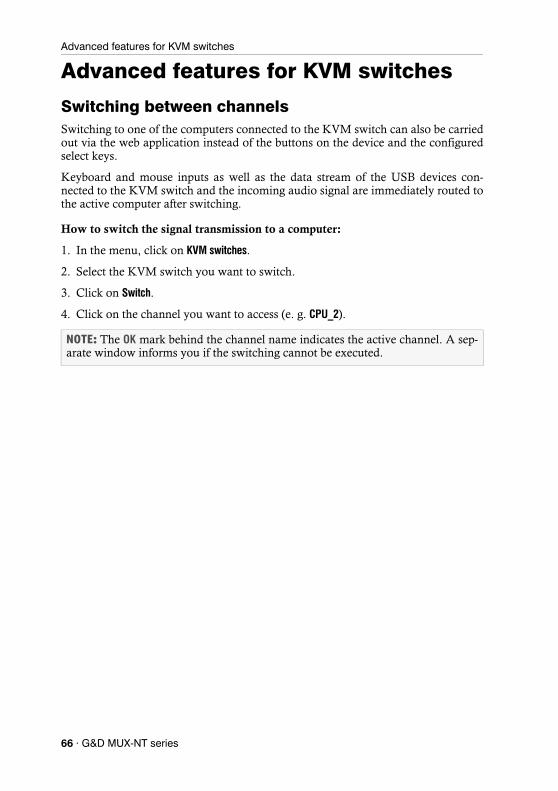
Advanced features for KVM switches
Advanced features for KVM switches
Switching between channelsSwitching to one of the computers connected to the KVM switch can also be carried out via the web application instead of the buttons on the device and the configured select keys.
Keyboard and mouse inputs as well as the data stream of the USB devices con-nected to the KVM switch and the incoming audio signal are immediately routed to the active computer after switching.
How to switch the signal transmission to a computer:
1. In the menu, click on KVM switches.
2. Select the KVM switch you want to switch.
3. Click on Switch.
4. Click on the channel you want to access (e. g. CPU_2).
NOTE: The OK mark behind the channel name indicates the active channel. A sep-arate window informs you if the switching cannot be executed.
66 · G&D MUX-NT series

Advanced features for KVM switches
Configuring monitoring valuesIn the Monitoring section, you can define values to be monitored and check the status of these values.
Selecting the values to be monitored
By default, the KVM system monitors a variety of different values of the KVM switch.
If required, you can limit the evaluation and monitoring of properties.
How to manage the values to be monitored:
1. In the menu, click on KVM switches.
2. Click on the KVM switch you want to configure and then click on Configuration.
3. Click on Monitoring.
4. Enable or disable individual monitoring values by sliding the slider to the left (off) or to the right (on).
5. Click on Save.
NOTE: In order to enable or disable all values you can use the check box in the header of the Enabled column.
G&D MUX-NT series · 67
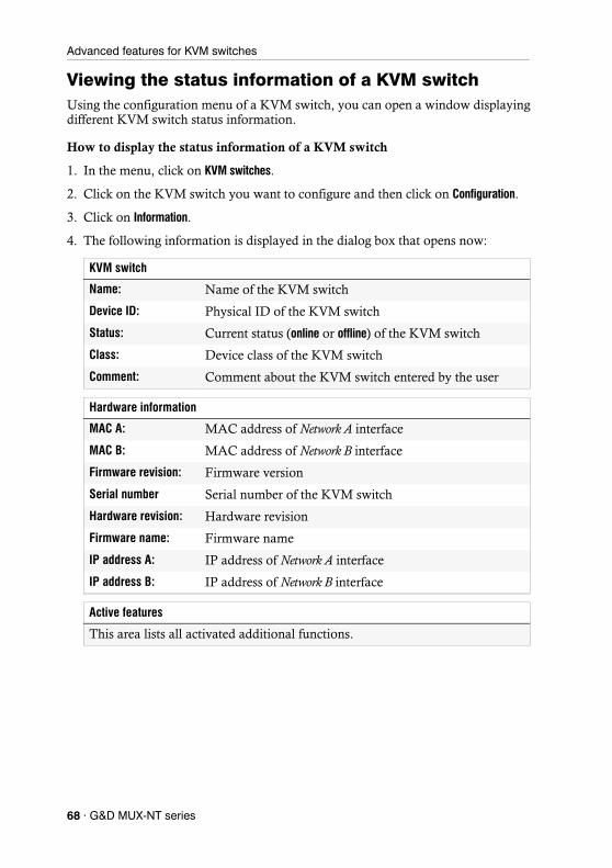
Advanced features for KVM switches
Viewing the status information of a KVM switchUsing the configuration menu of a KVM switch, you can open a window displaying different KVM switch status information.
How to display the status information of a KVM switch
1. In the menu, click on KVM switches.
2. Click on the KVM switch you want to configure and then click on Configuration.
3. Click on Information.
4. The following information is displayed in the dialog box that opens now:
KVM switch
Name: Name of the KVM switch
Device ID: Physical ID of the KVM switch
Status: Current status (online or offline) of the KVM switch
Class: Device class of the KVM switch
Comment: Comment about the KVM switch entered by the user
Hardware information
MAC A: MAC address of Network A interface
MAC B: MAC address of Network B interface
Firmware revision: Firmware version
Serial number Serial number of the KVM switch
Hardware revision: Hardware revision
Firmware name: Firmware name
IP address A: IP address of Network A interface
IP address B: IP address of Network B interface
Active features
This area lists all activated additional functions.
68 · G&D MUX-NT series
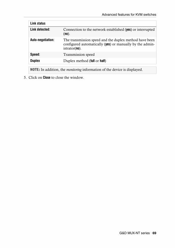
Advanced features for KVM switches
5. Click on Close to close the window.
Link status
Link detected: Connection to the network established (yes) or interrupted (no).
Auto-negotiation: The transmission speed and the duplex method have been configured automatically (yes) or manually by the admin-istrator(no).
Speed: Transmission speed
Duplex Duplex method (full or half)
NOTE: In addition, the monitoring information of the device is displayed.
G&D MUX-NT series · 69

�����

�����

�����

�����

Guntermann & Drunck GmbH Obere Leimbach 9 57074 Siegen Germany http://[email protected]
The manual is constantly updated and available on our website. http://gdsys.de/A9200153