gamefisher - appliance parts | replacement water …€¦ · · 2007-09-29one year limited...
TRANSCRIPT

SEARS
OWNER'SMANUAL
MODEL NO.
225.58150815" TRANSOM
225.58149820" TRANSOM
CAUTION:Read and Follow
all Safety Rulesand Instructions
Before OperatingThis Equipment
GAMEFISHER15 HORSEPOWEROUTBOARD MOTORWITH 6 GALLON REMOTE TANK
• Installation
• Operation
• Customer Responsibilities
• Service Adjustments
• Repair Parts
Sears Roebuck and Co., Hoffman Estates, IL 60179 U.S.A.

ii i iii i I
SAFETY RULES
BOATER'S RESPONSIBILITIES
The operator (driver) is responsible for the correct and
safe operation of the boat and safety of its occupants
and general public. It is strongly recommended that
each operator (driver) read and understand this entire
manual before operating the outboard.
Be sure at least one additional person on board isinstructed in the basics of starting and operating theoutboard and boat handling in case the driver is unableto operate the boat.
BEFORE OPERATING YOUR OUTBOARD
Read this manual carefully. Learn how to operate youroutboard properly. If you have any questions, contactyour nearest Sears Store which sells Gamefisher out-board motors.
Safety and operating information that is practiced alongwith using good common sense can help prevent per-sonal injury and product damage.
This manual as well as safety labels posted on the out-board use the following safety alerts to draw your atten-tion to special safety instructions that should be fol-lowed.
IMMEDIATE HAZARDS WHICH WILL RESULT INSEVERE PERSONAL INJURY OR DEATH.
USING AN OUTBOARD THAT EXCEEDS THE MAXI-MUM HORSEPOWER LIMIT OF A BOAT CAN:1. CAUSE LOSS OF BOAT CONTROL, 2. PLACE TOOMUCH WE|GHT AT THE TRANSOM ALTERING THEDESIGNED FLOTATION CHARACTERISTICS OFTHE BOAT OR 3. CAUSE THE BOAT TO BREAKAPART PARTICULARLY AROUND THE TRANSOMAREA. OVERPOWERING A BOAT CAN RESULT INSERIOUS INJURY, DEATH OR BOAT DAMAGE.
DO NOT attempt to make repairs or adjustments notspecifically covered in this manual. Should you everneed technical assistance, please contact your SearsService Center.
NEVER OPERATE your motor at full throttle when theengine is overloaded. This can occur under conditionswhen a planing boat is loaded so it does not plane orwhen towing another boat.
• Some boats are extremely unstable in the water, evenwhen secured to a dock. Do not stand erect. Stay asclose as possible to centerline of boat while installingmotor.
• DO NOT store your motor or gasoline where fumesmay reach an open flame and cause a fire.
DRAIN THE GASOLINE from your motor beforetransporting your motor inside your car or othervehicle.
HAZARDS OR UNSAFE PRACTICES WHICH COULDRESULT IN SEVERE PERSONAL INJURY OR DEATH.
I _ .CAUTION IHAZARDS OR UNSAFE PRACTICES WHICH COULDRESULT IN MINOR INJURY OR PRODUCT OR PRO-PERTY DAMAGE.
ALWAYS DISCONNECT SPARK PLUG WIRES ANDPLACE WIRES WHERE THEY CANNOT CONTACTSPARK PLUGS TO PREVENT ACCIDENTAL START-ING WHEN WORKI_IG ON YOUR OUTBOARDMOTOR.
• DO NOT use a motor with a horsepower rating higherthan what is listed (_nthe certification plate on yourboat.
GASOLINE AND ITS VAPORS ARE EXTREMELYFLAMMABLE AND HIGHLY EXPLOSIVE UNDERCERTAIN CONDITIONS. ALWAYS STOP THE EN-GINE AND DO NOT SMOKE OR ALLOW OPENFLAMES OR SPARKS IN THE AREA WHILE FILLINGFUEL TANKS.
• DO NOT fill the gas tank when the engine is running.Do not fill the gas tank indoors.
• REMOVE portable fuel tank from boat when refuelingto prevent spilling fuel in boat. Always mix fuel in awell ventilated area.
2

CONGRATULATIONS...
You are to be congratulated on your selection of thisOutboard Motor which will give you years of satisfactoryservice. Your Gamefisher is the end product of years ofresearch, engineering and development. It has beenassembled by Craftsmen who take pride in their work.
This Owner's Guide will help you to receive all thetrouble-free performance built into your motor. READTHROUGH THIS MANUAL CAREFULLY BEFOREOPERATING THE MOTOR. It contains complete operat-ing instructions and recommendations for the care andprotection of your motor. Following these recommenda-tions and instructions will assure you of years of boatingpleasure.
I
Outboarding is a great _port. Always remember, how-ever, that you have friends on the water. Extend to themthe courtesy of thoughtful, safe operation of your motorand boat and you will increase your own enjoyment.
MODELNUMBER
SERIALNUMBER
DATE OFPURCHASE
THE MODEL AND SERIAL NUMBERS WILL BEFOUND ON A DECAL ATTACHED TO THE PORTSTERN BRACKET.
YOU SHOULD RECORD BOTH SERIAL NUMBERAND DATE OF PURCHASE AND KEEP IN A SAFEPLACE FOR FUTURE REFERENCE.
PRODUCT SPECIFICATIONS
Engine 15 HP
Horsepower Rating @ 6000 RPM
Recommended 5500 - 6500 RPMOperating Range
Engine Type Two Cycle, Two CylinderAlternate Firing
2.25" x 1.94"Bore and Stroke
57.1 mm x 49.2 mm)
Cubic Inch 15.41 Cubic InchesDisplacement (252.5 cc)
Water Cooled - DisplacementCooling Type Water Pump
Propeller Right Hand Rotation,Spline Drive
Spark Plug - Champion 33-328
Spark Plug Gap 0.040 in. (1.0 mm)
Fuel Tank Remote 6.0 gal. (23 L)
Gear Ratio 14:22
15" Leg = 62 Ibs. (28.1 Kg)Weight (approx.) 20" Leg = 64 Ibs. (29.0 Kg)
25:1 Break-InFuel:Oil Ratio 50:1 Normal
CUSTOMER RESPONSIBILITIES
• Read and observe the safety rules.
• Follow a regular schedule in maintaining, caring forand using your outboard motor.
• Followthe instructions under"Cus.tomer Responsibil-ities" and "Storage" sections of this Owner's Manual.
ONE YEAR LIMITED WARRANTY ON GAMEFISHER OUTBOARD MOTORFor one year from the date of purchase, when this Gamefisher Outboard Motor ismaintained, lubricated and tuned-up according to the instructions inthe owner's manual, Sears will repair,free of charge, any defect in material andworkmanship.
Ifthis Gamefisher Outboard Motor is used for commercial orrental purposes, thiswarranty applies foronly 90 daysfrom the date of purchase.
This warranty does not cover:
• Expendable items which become worn during normal use, such as sparkplugs, water pump impeller, oil seals,propellers and tune-ups.
• Repairs necessary because of operator abuse or negligence, includingbutnot limited to strikingan underwaterobject and failure to maintain the equipment according to the instructionscontained in the owner's manual.
WARRANTY SERVICE IS AVAILABLE BY RETURNING THE GAMEFISHER OUTBOARD MOTOR TO THENEAREST SEARS SERVICE CENTER/DEPARTMENT IN THE UNITED STATES. THIS WARRANTY APPLIESONLY WHILE THIS PRODUCT IS IN USE IN THE UNITED STATES.
This warranty gives you specific legal rights, and you may also have other rightswhich may vary from state tostate.
._ SEARS, ROEBUCK AND CO. Department 817WA, Hoffman Estates, IL 60179

TABLE OF CONTENTS
SAFETY RULES ................................. 2
MOTOR SPECIFICATIONS ...................... 3
WARRANTY ..................................... 3
MOTOR ACCESSORIES ......................... 5
INSTALLATION ................................. 7
MOTOR NOMENCLATURE ...................... 8
OPERATION ................................. 8-16
CUSTOMER RESPONSIBILITIES ............. 17-24
SERVICE AND ADJUSTMENTS ................. 25
STORAGE .................................. 26-27
TROUBLESHOOTING POINTS .................. 28
REPAIR PARTS ................................ 29
PARTS ORDERING .................. REAR COVER
INDEX
B
Before Starting Engine ....... 12
Boat Transom ................ 7
Break-In Procedure .......... 13
C
Carburetor .................. 25
Cooling System ............. 15
Customer Responsibilities .... 17
D
Draining/Refilling Gear
Housing Lubricant ......... 23
E
Exterior Care ................ 27
F
Fuel Pump Filter ............. 19
Fuel Ratio Conversion Table .o 12
Fuel System ................ 11
Fuel Tank Filter ............. 19
G
Gasoline Selection .......... 12
General Recommendations... 17
I
Index ........................ 4
K
Know Your Outboard Motor . .. 8
L
Lanyard Stop Switch .......... 6Lubrication Schedule ........ 17
Lubrication Code ............ 22
M
Maintenance Schedule ....... 17
Mounting Motor .............. 7
Motor Tilt Angle ............. 11
Motor Speed (RPM) andPropeller ................. 15
Motor Tilt .................... 9
O
Oil Selection ................ 12
Operating Checks ........... 15
Operating In FreezingTemperatures ............. 16
P
Pre-Operation Checklist ..... 16
Product Specifications ........ 3
Propeller ................... 11
Propeller Removal ........... 21
R
Removing Motor ............. 7
Remove Motor Cover ........ 18
S
Salt Water Operation ........ 16Shakedown Checklist ........ 16
Shallow Water Drive Bar ..... 10
Spark Plug .................. 20
Start Engine ................ 14
Steering Friction ............. 9
Storage ..................... 26
Submerged MotorFresh Water ............... 24
Submerged MotorSalt Water ................ 24
T
Tiller Handle Position ........ 10
Throttle Stop ................ 25
Troubleshooting Chart ....... 28
W
Warranty .................... 3

OUTBOARD MOTOR ACCESSORIES
These accessories were available when the outboard motor was purchased. They are also available at most Sears retail
outlets, catalog and service centers. Most Sears stores can order repair parts for you, when you provide the model number
of your outboard motor.
SPARK PLUG OUTBOARD OILTC-W3 or TC-W !1
i
FUEL STABILIZER GEAR LUBE
PROPELLER APPLICATION
opuonal - Veryug_ Loads
Optional- Ught Loads
Optional - Light Loads
Standard - Average Loads
Optional - Average Loads
Optional - Medium/Heavy Loads
Optional - Heavy Loads
Optional - Heavy Loads/Sailboat
NO. OF DIA.BLADES (IN.)
3 8
3 8
2 8 1/4
3 8
2 8 1/4
3 8 3/8
3 8 1/4
3 8 1/4
PITCH(IN.)
9
8 1/4
8 1/4
9 1/4
8 3/4
6
6
4 1/2
MATERIAL
Aluminum
Nylon
Aluminum
Nylon
Aluminum
Aluminum
Aluminum
Aluminum
PART NO.
P-472
P-6430
P-286-3
P-6477
P-70
P-715
P-395
P-396
5
i ii
GENERAL INFORMATION
LANYARD STOP SWITCH
1 The purpose of the lanyard stop switch is to turn off
the engine ignition whenever the operator (when at-
tached to the lanyard) moves far enough away from the
operator's position to activate the switch.
2 The lanyard is a cord usually between 4 and 5 feet in
length when stretched out with an element on one endmade to be inserted into the switch and a metal snap on
the other end for attaching to the operator. It is coiled to
make its at-rest condition as short as possible so as to
minimize the likelihood of the lanyard entanglement
with nearby objects. It is made as long as it is in itsstretched condition to minimize the likelihood of acci-
dental activation should the operator choose to move
around in an area close to the normal operator's posi-
tion. If for any reason it is desired to have a shorter
functional lanyard, this may be accomplished by using
up length in the way the lanyard and clip are attached to
the operator (such as wrapping the lanyard around the
operator's wrist or leg) or by tying a simple knot in the
lanyard.
Read the Safety Warning following before electing touse or not to use such a switch.
THE FOLLOWING ADVANTAGES AND DISADVAN-TAGES OF A LANYARD STOP SWITCH SHOULD BECONSIDERED BEFORE ELECTING TO USE, OR NOTTO USE, SUCH A SWITCH.
ADVANTAGES: THE PURPOSE OF A LANYARD STOPSWITCH IS TO STOP THE ENGINE IGNITION WHEN-EVER THE OPERATOR (WHEN ATTACHED TO THELANYARD) MOVES FAR ENOUGH AWAY FROM THEOPERATOR'S POSITION TO ACTIVATE THESWITCH. THIS WOULD OCCUR IF THE OPERATORFALLS OR MOVES WITHIN THE BOAT A SUFFI-CIENT DISTANCE FROM THE OPERATOR'S POSI-TION. THIS TYPE OF ACCIDENT IS MOST LIKELY INCERTAIN TYPES OF BOATS SUCH AS LOW-SIDEDBASS BOATS, HIGH-PERFORMANCE BOATS ANDLIGHT, SENSITIVE-HANDLING FISHING BOATSOPERATED BY HAND-TILLER. IT IS ALSO LIKELY ASA RESULT OF POOR OPERATING PRACTICES SUCHAS SITTING ON THE BACK OF THE SEAT AT PLAN-ING SPEEDS, STANDING AT PLANING SPEEDS,OPERATING AT HIGH SPEEDS IN SHALLOW OROBSTACLE-INFESTED WATERS, RELEASING YOURGRIP ON A STEERING WHEEL THAT IS PULLING INONE DIRECTION, DRINKING AND DRIVING ORDARING, HIGH-SPEED BOAT MANEUVERS.
DISADVANTAGES: INADVERTENT ACTIVATION OF
THE SWITCH IS ALSO A POSSIBILITY. THIS COULD
CAUSE ANY, OR ALL, OF THE FOLLOWING POTEN-TIALLY HAZARDOUS SITUATIONS:
1, LOSS OF BALANCE AND FALLING FORWARD OFUNSTABLE BOAT PASSENGERS- A PARTICULARCONCERN IN BOW RIDER TYPE BOATS.
2. LOSS OF POWER AND DIRECTIONAL CONTROL
IN HEAVY SEAS, STRONG CURRENT OR HIGHWINDS.
3. LOSS OF CONTROL WHEN DOCKING.
IN ADDITION, THERE ARE LIMITATIONS TO WHATTHE LANYARD STOP SWITCH CAN DO. THE BOAT
CAN CONTINUE TO COAST FOR A CONSIDERABLEDISTANCE DEPENDING ON THE VELOCITY AT
SHUTDOWN AND THE DEGREE OF ANY TURN.
HOWEVER, THE BOAT WILL NOT COMPLETE A
FULL CIRCLE. WHILE THE BOAT IS COASTING, ITCAN CAUSE INJURY TO ANYONE IN THE BOAT'S
PATH AS SERIOUSLY AS THE BOAT WOULD WHENUNDER POWER.
AS WE CANNOT POSSIBLY KNOW OF AND ADVISETHE BOATING PUBLIC OF ALL CONCEIVABLE
BOAT/MOTOR TYPES AND/OR POOR OPERATING
PRACTICES, THE FINAL DECISION OF WHETHERTO USE A LANYARD STOP SWITCH RESTS WITH
YOU, THE OWNER/DRIVER.
WE STRONGLY RECOMMEND THAT OTHER OCCU-PANTS BE INSTRUCTED ON PROPER STARTING
AND OPERATING PROCEDURES SHOULD THEY BEREQUIRED TO OPERATE THE OUTBOARD AND
BOAT IN AN EMERGENCY.
6

INSTALLATION
BOATTRANSOM
TRANSOM TYPE
• Make sure the transom of your boat is designed formounting an outboard motor. (Figure 1) The keelshould be tapered from a point about 30" (76.2cm)ahead of the transom so that it is no more than 1/2"
(1.27cm) thick at the transom.
MOUNTING MOTOR
• Mark the vertical centerline (exact middle) of thestern of the boat.
• Center the motor on the transom.
IMPORTANT: IF THE MOTOR IS NOT CENTERED ON
THE TRANSOM, THE TORQUE OF THE PROPELLERWILL TEND TO CAUSE THE BOAT TO RUN OFF
COURSE AND CREATE HARD STEERING AND CON-
TROL.
SOME BOATS ARE UNSTABLE IN THE WATER, EVENWHEN SECURED TO A DOCK. DO NOT STANDERECT. STAY AS CLOSE AS POSSIBLE TO CENTER-LINE OF BOAT WHILE INSTALLING MOTOR.
• Raise or lower the motor until the anti-cavitation
plate is 1/2" to 1" below the bottom of the boat.(Figure 2)
• Tighten stern bracket clamp screws alternately byhand until tight. (Figure 3)
IMPORTANT: DO NOT USE WRENCH TO TIGHTENCLAMP SCREWS.
REMOVING MOTOR
• To remove the motor from the boat, simply reversethe installation procedure.
IMPORTANT: WHEN REMOVING, MAINTAIN MOTORIN AN UPRIGHT POSITION RESTING ON IT'S SKEGUNTIL ALL WATER HAS DRAINED FROM THEMOTOR LEG.
OK OK
NOT SUITABLE NOT SUITABLE
FIGURE 1
ANTI-CAVITATION
(1.27 crn) -- (2.54
FIGURE 2
FIGURE 3

OPERATION
KNOW YOUR OUTBOARD MOTOR
Read this owner's manual and safety rules before operating your outboard motor. Compare the illustrations (Figures 4
and 5) with your outboard motor to familiarize yourself with the location of various controls and adjustments. Save thismanual for future reference.
2OO
14
- 10
9
25
15
22
17
FIGURE 4
1 MotorCover
2 Motor CoverLatch
3 IdleRelief HolesfThermostat
4 MotorLeg5 Anti-CavitationPlate
6 Propeller7 Skeg8 WaterInlet
9 Gear Housing10 Stem Brackets
11. "131tReleaseLever
12 ShiftLever
13 Stop Switch14 ThrotUe/SteedngArm
18
FIGURE 5
15 StartingDecal:Explains how to startyourmotor.16 Warm-Up Knob:Puffingthewarm-upknoboutrichensthe fuel/
air mixture when startinga coldmotor.17 "ritltrelease Lever:Rotatingthe tilt release leverenables the
motor to be tiltedup.18 ShallowWaterDriveBar:The shallowwaterdrivebar allows
operatingat lowspeedsinshallowwater.
19 MotorLock Bar:Movingthe motorlockbar changesthe tiltangle of themotor.
20 GearShift Lever:Allowsshiftinginand out of neutral,forwardand reversegear.
21 LanyardSwitch:Pullingthecordshutsthe motoroff inan emer-gencysituation.
22 Twist-GripThrottle:Tumingthethrottleallowsyou to increaseanddecrease speed.It alsohas twopositiod_:(1) Start - usedwhenstartingmotor; and (2) Shift - used beforeshiftingmotorto forward orreversegear.
23 Primer:Pushingtheprimerbuttonsuppliesa smallamountoffuelto thecarburetorfor starting.
24 Starter RopeHandle:Pullingthe starterropeturns the motorover forstarting.
25 StopButton:Pushingthe stopbuttonstopsthe motor.
8

OPERATION
HOW TO USE YOUR OUTBOARD MOTOR
MOTOR TILT
• To tilt the motor up out of the water push tilt releaselever down to "Release" position. (Figure 6)
• Grasp handle on back of motor cover and pull forward
until end of travel of tilt stop. Push tilt stop down tolock motor in tilt position. (Figure 7)
• Return motor to operating position. Grasp handle onback of motor cover and pull slightly forward. Pull thetilt stop up to release motor. (Figure 8)
• Push the tilt release lever up to engage position.(Figure 9)
RELEASE
FIGURE 6
TILT STOP
FIGURE 7
TILTSTOP
FIGURE 8
ENGAGE
FIGURE 9
STEERING FRICTION
STEERING FRICTION ADJUSTMENT IS NOT IN-TENDED TO ALLOW "HANDS OFF" STEERING.LOSS OF CONTROL AND SERIOUS INJURY COULDRESULT.
• Adjust screw for steering friction desired. (Figure 10)
FIGURE 10

J
ii i i
OPERATION
SHALLOW WATER DRIVE BAR
The shallow water drive bar allows the motor to operateat low speeds in shallow water.
• Tilt the motor and lock it in the up position. (See Motor
Tilt, page 9).
• Lift the shallow water drive bar up until it clicks into its"up" position. (Figure 11)
• Pull the tilt stop up and slowly lower the motor makingsure that the shallow drive bar rests against the motorlock bar. (Figure 12)
TILLER HANDLE POSITIONS
The motor is equipped with a throttle arm that drops
down for convenient handling during transportation orstorage. To drop the handle, lift the arm up slightly,
push and hold the lock lever down. (Figure 13) Drop thehandle until it clears the lock lever. (Figure 14)
SHALLOW WATER BAR//
FIGURE 11 FIGURE 13
LOCK BAR
FIGURE 12
f\\/
\
FIGURE 14
10

OPERATION
MOTOR TILT ANGLE
IMPORTANT: ADJUST MOTOR TILT ANGLE, IF NECESSARY, BY CHANGING THE POSITION OF THE LOCKBAR SO THAT THE PROPELLER SHAFT IS PARALLEL TO THE SURFACE OF THE WATER WHEN THE BOAT IS
PLANING. SEE FIGURE 15 TO DETERMINE CORRECT MOTOR ANGLE.
• Adjust motor angle if motor is too close to transom or bow will dig in or plow.
LOCK BAR TOO LOW,MOTOR TOO CLOSE
-2CORRECT
LOCK BAR TOO HIGH,MOTOR TOO FAR OUT
FIGURE 15
• Adjust motor angle, if motor is too far away from transom the bow may ride high, the boat may "porpoise," andthe motor may race.
PROPELLER
• Your engine is equipped with a general duty propeller which should give you good all around Operating charac-teristics on a typical boat for this size engine.
• CJ_eck that motor is not over-revving (RPM too high) or lugging (RPM too low) at wide open throttle. Optionalpropellers may be ordered from Sears.
11

OPERATION
BEFORE STARTING ENGINE
OIL SELECTION
• Use NMMA certified TC-W3 or TC-W II outboard oil.
GASOLINE SELECTION
• 87 pump octane minimum, premium not needed.
• 10% ethanol maximum.
• 3% methanol maximum.
• Use a major fuel supplier.
IMPORTANT: Experience indicates that alcoholblended fuels (called gasohol or using ethanol ormethanol) can attract moisture which leads to separa-tion and formation of acids during storage. Acidic gascan damage the fuel system of an engine while in stor-age. To avoid engine problems, the fuel system shouldbe emptied before storage for 30 days or longer. Drainthe gas tank, start the engine and let it run until the fuellines and carburetor are empty. Use fresh fuel nextseason. See Storage Instructions for additional infor-mation. Never use engine or carburetor cleaner pro-ducts in the fuel tank or permanent damage may occur.
FOR A PROPER FUEL MIX
Recommended lubricant and gasoline must be properlymixed or serious damage will result to the engine.
• Maintain a clean fuel tank.
• Strain fuel through a fine mesh strainer.
• Pour one (1) gallon (38.1 cm) of fresh gasoline into anempty fuel tank. Add proper amount of outboard mo-tor oil. Add balance of gasoline, mix thoroughly.
TO PREVENT SPILLING FUEL IN BOAT, REMOVEPORTABLE FUEL TANK WHEN REFUELING. GASO-LINE IS HIGHLY FLAMMABLE -- ALWAYS MIX INWELL VENTILATED AREA.
• Observe safety rules - mix fuel in a well ventilatedarea (preferably outdoors). Avoid sparks and openflames.
• Repeated use of additive compounds such as"break-in" oils, "tune-up" compounds, "tonics", "fric-tion reducing" compounds, etc. is not recommended.
USE ORSERVICE FUEL RATIO CONVERSION TABLE
RATIO GASOLINE QTY. OIL QTY.
Break-in 1 Gallon25:1 3.8 Liters 1/3 Pint 5.3 oz, .158 Liters
or 3 Gallons (2.5 Imp. Gal.)11.5 Liters 1 Pint 16 oz. .473 Liters
4% Oil 6 Gallons (5 Imp. Gal.)5 Liters 2 Pints 32 oz. .946 Liters
Normal 1 Gallon50:1 3.8 Liters 1/6 Pint 2.6 oz. .079 Liters
or 3 Gallons (2.5 Imp. Gal.) 1/2 Pint 8 oz. .236 Liters11.5 Liters
2% Oil 6 Gallons (5 Imp. Gal.)23 Liters 1 Pint 16 oz. .473 "Citers
NOTE: Regular use of a fuel stabilizer can help avoid fuel problems during short storage periods. Mix stabilizer accordingto bottle instructions during each fill up to be sure it will be present during unplanned storage.
12

I
• II II I
OPERATION
BREAK-IN PROCEDURE -- USE 25:1 MIX
I ,A CAUTION ]SEVERE DAMAGE TO THE ENGINE CAN RESULTBY NOT COMPLYING WITH THE FOLLOWINGBREAK-IN PROCEDURE.
• Mix correct amount of outboard motor oil with eachgallon of gasoline (see gasoline -- oil mixture require-ments and fuel ratio conversion table).
• Run engine at moderate speed (approximately 1/2throttle) for ten minutes. Check operation of thewater pump and cooling system. (Refer to "CheckingWater Pump Operation.")
• Advance to full throttle for a few seconds.
• Return to moderate speed for several minutes.
• Repeat steps 2 and 3 gradually increasing time of fullthrottle operation until 5 minutes of full throttle oper-ation has been reached. This break-in operation willrequire approximately one (1) hour running time.
• Use the 25:1 gasoline-oil for an additional two (2)hours before changing to the 50:1 mixture for normaluse.
• AVOID CONTINUOUS FULL THROTTLE OPERA-TION FOR AN ADDITIONAL TWO (2) HOURS.
• Your outboard motor may now be operated at anythrottle setting desired using the proper fuel ratio asspecified in the gasoline-oil chart.
DISCONNECT FUEL LINE IF MOTOR IS NOT USEDFOR ANY LENGTH OF TIME. FAILURE TO DO SOCOULD RESULT IN FUEL LEAKAGE INTO THEBOAT.
• Observe required maintenance and operating in-structions.
FUEL SYSTEM
I _ CAUTION 1CHECK WITH YOUR SEARS STORE BEFORE USINGANY FUEL TANK; TO MAKE SURE THE LINE, VENTAND CHECK VALVE ARE SAFE, AND ARE THECORRECT SIZE.
• Place fuel tank in a secure level place out of the way.
• Connect fuel line to quick-disconnect fitting in frontof motor. (Figure 16)
• Slide back sleeve in coupler.
• Place sleeve on bushing and release to lock in place.
FIGURE 16
• Carburetor.
Your motor's carburetor is preset at tll_ factory fornormal operation. If you are operating at varying alti-tudes or temperature conditions you may need toreadjust the carburetor for best operation. See Car-buretor (page 25) in Service and Adjustments section.
13
OPERATION
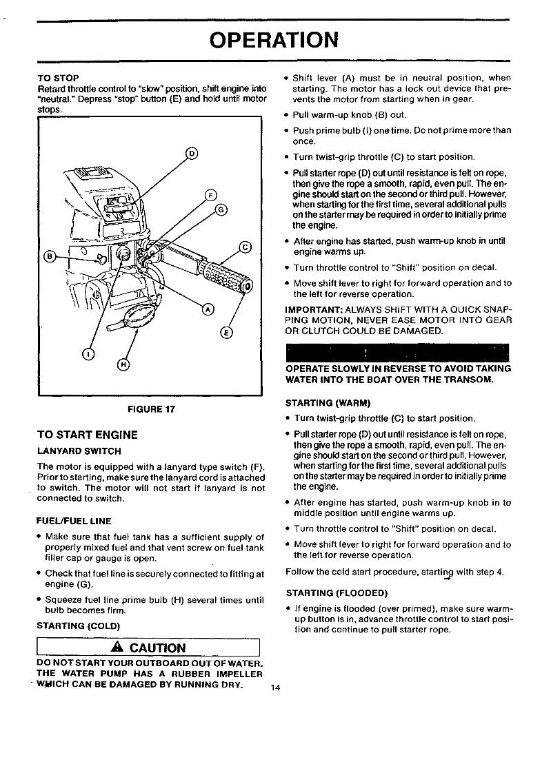
TO STOPRetard throttle control to "slow" position, shift engine into"neutral." Depress "stop" button (E) and hold until motorstops.
®
• Shift lever (A) must be in neutral position, whenstarting. The motor has a lock out device that pre-vents the motor from starting when in gear.
• Pull warm-up knob (B) out.
• Push prime bulb (I) onetime. Do not prime more thanonce.
• Turn twist-grip throttle (C) to start position.
• Pull starter rope (D) out until resistance is felt on rope,then give the rope a smooth, rapid, even pull. The en-gine should start on the second or third pull. However,when starting for the first time, several additional pullson the starter may be required in order to initially primethe engine.
• After engine has started, push warm-up knob in untilengine warms up.
• Turn throttle control to "Shift" position on decal.
• Move shift lever to right for forward operation and tothe left for reverse operation.
IMPORTANT: ALWAYS SHIFT WITH A QUICK SNAP-PING MOTION, NEVER EASE MOTOR INTO GEAROR CLUTCH COULD BE DAMAGED.
OPERATE SLOWLY IN REVERSE TO AVOID TAKINGWATER INTO THE BOAT OVER THE TRANSOM.
FIGURE 17
TO START ENGINE
LANYARD SWITCH
The motor is equipped with a lanyard type switch (F).Prior to starting, make sure the lanyard cord is attachedto switch. The motor will not start if lanyard is notconnected to switch.
FUEL/FUEL LINE
• Make sure that fuel tank has a sufficient supply ofproperly mixed fuel and that vent screw on fuel tankfiller cap or gauge is open.
• Check that fuel line is securely connected to fitting atengine (G).
• Squeeze fuel line prime bulb (H) several times untilbulb becomes firm.
STARTING (COLD)
[ A, CAUTIONDO NOT START YOUR OUTBOARD OUT OF WATER.THE WATER PUMP HAS A RUBBER IMPELLER
• WJblICH CAN BE DAMAGED BY RUNNING DRY. 14
STARTING (WARM)
• Turn twist-grip throttle (C) to start position.
• Pull starter rope (D) out until resistance isfelt on rope,then give the rope a smooth, rapid, even pull. The en-gine shouldstart on the second or third pull. However,when startingfor the first time, several additional pullson the starter may be required in order to initiallyprimethe engine.
• After engine has started, push warm-up knob in tomiddle position until engine warms up.
• Turn throttle control to "Shift" position on decal.
• Move shift lever to right for forward operation and tothe left for reverse operation.
Follow the cold start procedure, starting with step 4.
STARTING (FLOODED)
• If engine is flooded (over primed), make sure warm-up button is in, advance throttle control to start posi-tion and continue to pull starter rope.

OPERATION
OPERATING CHECKS
COOLING SYSTEM
Cooling water ispicked up on the side ofthe gear housingjust ahead of the propeller, goes through the powerhead,and then goes out with the exhaust gases.
IMPORTANT: NEVER RUN MOTOR OUT OF THE WA-TER, AND NEVER RUN MOTOR UNLESS WATER PUMPIS WORKING NORMALLY OR OVERHEATING AND MO-TOR DAMAGE MAY RESULT.
• Check that a spray of water is coming out of the idlerelief holes when the motor is idling. (Figure 18)
/
FIGURE 18
OPERATING PRECAUTIONS
Avoid striking underwater objects especially in re-verse, since both the motor and the transom may bedamaged. (Figure 19)
If an object is hit, stop and check for damage.
While operating in reverse or in forward, faster thantrolling speed, engage tilt release/reverse lock.
If you operate in very shallow water, you may plug the
water inlet with mud or debris which will cause yourmotor to overheat.
Avoid shallow water. If you must operate in shallowwater or in an area where there are known obstruc-
tions, use shallow water driver" bar (page 10).
If while operating your boat the propeller comes in
contact with fishing line, stop motor. Visually inspectand remove any line that is wrapped around prop. Assoon as possible, remove engine from water andcheck gear housing for water which would indicate ada_naged seal.
AND CHECK
i
FIGURE 19
MOTOR SPEED (R.RM.) AND PROPELLER
IMPORTANT:. TO AVOID MOTOR DAMAGE, THE MO-TOR MUST BE RUNNING IN THE RIGHT OPERATINGRANGE AND THE PROPELLER MUST BE CORRECT FORTHE BOAT.(SEE SPECIRCATIONS).
• At wide open throttlecheck that motor R.P.M. is withinspecifications.
• Ifyour motorseems to be runningwell but is not in thecorrect R.RM. range, you may need a propeller witha different pitch (a smaller pitch increases R.P.M.while a larger pitch decreases R.RM.). Consult yourSears Store.
PRE-OPERATION CHECKLIST
13 Operator knows safe navigation, boating and operat-ing procedures.
[] All needed safety equipment is on board, in goodcondition and easy to reach.
[] Motor isoperating normally. Ifthe motor is hard to startor is not runningwell, have repairs made before leav-ing dockside.
[] Fuel supply is O.K.
[] Use only recommended gasoline and oil and useonly the correct mixture.
[] There are no fuel leaks.
[] Propeller is not fouled or damaged.
[] A spare propeller is on board.Ip
[] The correct anchor and lines are on board.
[] All anchor and mooring lines are neatly coiled out ofthe way.
[] Recreational equipment and fishing gear is stowedsecurely.
F__]Bilge is pumped and there are no water leaks.
[] Passengers are safely on board.
[] The area is clear for operation. Operator is aware ofother boats, skiers, divers, swimmers, etc.
15

OPERATION
SHAKEDOWN CHECKLIST
[] Operator has read and understood the entire opera-tor's manual.
[] Operator has carried out pre-operation checklist.
[] Operate cautiously and get to know how your boathandles.
[] If the motor is new, follow all break-in procedures.
[] Follow all operating procedures.
[] Check tightness of mounting clamps.
[] Adjust motor angle if necessary.
[] Adjust idle if necessary.
[] Adjust carburetor if necessary.
[] Check that propeller is correct for boat.
OPERATING IN FREEZINGTEMPERATURES
• When using the motor in freezing or near freezing tem-peratures, keep the gear housing in the water. Whenlaunching the boat/motor in near freezing"tempera-tures, let the rig soak for 20 to 30 minutes before start-ing to allow water in the water pick-up, water pump,or water tube to thaw.
IMPORTANT: IF THE MOTOR IS TILTED OUT OF THEWATER, WATER REMAINING IN THE COOLING SYSTEMAND GEAR HOUSING MAY FREEZE AND CAUSE PARTSTO BREAK.
• Do not start a motor that might be frozen.
SALT WATER OPERATION
Although all motor parts that contact water have beenchemically treated to resist salt water corrosion, youshould take some special steps after runningyour motorin salt water.
• Always tilt the motor out of the water when not inuse.
• From time to time run the motor in fresh water to flushout salt deposits.
• Wash motor down with fresh water and soap; rinse.Apply a marine-type wax to protect the finish.
• Periodically remove propeller and lubricate propellershaft.
• Replace water pump impeller every year. Apply anti-seize compound to the driveshaft/crankshaft spline.
i ,A CAUTIONIF OUTBOARD IS STORED TILTED UP IN FREEZINGTEMPERATURE, TRAPPED COOLING WATER ORRAIN WATER THAT MAY HAVE ENTERED THEEXHAUST OUTLET IN THE GEAR CASE COULDFREEZE AND CAUSE DAMAGE TO THE OUTBOARD.
16
CUSTOMER RESPONSIBILITIES
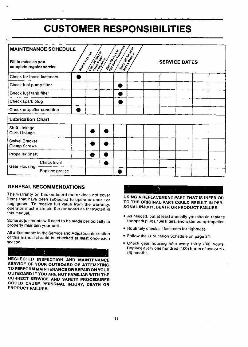
' / / _/_ /MAINTENANCE SCHEDULE/ ._ /.o,. / ._j/_o_.# /
F.,,._atesas.o,, I/' _;_lt._f l_"._t ..:#I/'&"'!.&_'!complete regular service / ._o- /Check for loose fasteners •
Check fuel pump filter •
Check fuel tank filter •
Check spark plug •
Check propeller condition •
SERVICE DATES
Lubrication Chart
Shift LinkageCarb Linkage • •
Swivel BracketClamp Screws • •
Propeller Shaft • •
Check level •Gear Housing
Replace grease •
GENERAL RECOMMENDATIONS
The warranty on this outboard motor does not cover
items that have been subjected to operator abuse or
negligence. To receive full value from the warranty,operator must maintain the outboard as instructed inthis manual.
Some adjustments will need to be made periodically toproperly maintain your unit.
All adjustments in the Service and Adjustments sectionof this manual should be checked at least once eachseason.
NEGLECTED INSPECTION AND MAINTENANCE
SERVICE OF YOUR OUTBOARD OR ATTEMPTING
TO PERFORM MAINTENANCE OR REPAIR ON YOUR
OUTBOARD IF YOU ARE NOT FAMILIAR WITH THE
CORRECT SERVICE AND SAFETY PROCEDURES
COULD CAUSE PERSGNAL INJURY, DEATH ORPRODUCT FAILURE.
USING A REPLACEMENT PART THAT IS INFERIOR
TO THE ORIGINAL PART COULD RESULT IN PER-
SONAL INJURY, DEATH OR PRODUCT FAILURE.
• As needed, but at least annually you should replacethe spark plugs, fuel filters, and water pump impeller.
• Routinely check all fasteners for tightness.
• Follow the Lubrication Schedule on page 22.
• Check gear housing lube every thirty (30) hours.Replace every one hundred (100) hours of use or six(6) months.
17

CUSTOMER RESPONSIBILITIES
TO REMOVE MOTOR COVER
DO NOT REMOVE OR INSTALL COVER WHILEMOTOR IS RUNNING. THE COVER PROTECTS YOUFROM MOVING PARTS, WHICH COULD CATCHHANDS, HAIR OR CLOTHING AND CAUSE SERIOUSINJURY.
• Push down hard on cover and turn cover release leveron rear of motor. (Figure 20)
• Lift cover up in rear and move cover to front to freeit from cover retainer. Lift cover up and off.
TO INSTALL MOTOR COVER
• Place cover retainer into slot in front of motor cover.(Figure 21)
• Push cover back slightly over seal.
• Push down and turn release lever to lock cover inplace.
PUSH DOWN
REAR
FIGURE 20
/COVER RETAINER
DOWN _
P
FIGURE 21
18

CUSTOMER RESPONSIBILITIES
FUEL PUMP FILTER
• Remove motor cover.
• Remove fuel line from pump. (Figure 22)
• Remove filter/fitting from pump cover.
NOTE: FILTER IS PART OF THE FUEL FITTING.
• Clean or replace filter.
• Reinstall filter/fitting and connect fuel line and securewith clamp.
AVOID SPILLING FUEL AND KEEP ALL SOURCESOF HEAT, FLAME AND SPARKS AWAY WHEN DIS-CONNECTING, HANDLING OR STORING FUELSYSTEM COMPONENTS.
PUMP COVER
FIGURE 22
FUEL TANK FILTER
• Disconnect fuel line from motor.
• Remove fuel connector assembly from fuel tank.
• Remove fuel filter from bottom of assembly (Figure23).
• Wash filter in clean solvent.
• Replace filter if rusted, corroded or damaged.
• Reinstall fuel connector assembly and reconnect fuelline.
FIGURE 23
19

CUSTOMER RESPONSIBILITIES
SPARK PLUG
• Remove motor cover.
• Disconnect spark plug lead by twisting slightly andpulling (Figure 24).
• Remove, clean and inspect spark plug. (Figure 25).
• Replace plug if tip of insulator is rough, cracked, bro-ken or blistered, or if the electrodes are eroded.
FIGURE 24
• Gap plug to .040 in. (1.0 mm) (Figure 26).
• Check spark plug gasket and carefully clean spark plugseat on cylinder head.
IMPORTANT: DO NOT OVERTIGHTEN SPARK PLUG ORDAMAGE TO CYLINDER HEAD MAY RESULT.
• Install plugfinger tight, and then tighten about 1/4 turn ortorque to 120 - 180 lb. in. (13.6 - 20.3 N-m).
• Install spark plug lead.
FIGURE 25
.040 in.
(1.0mm)
FIGURE 26
20

CUSTOMER RESPONSIBILITIES
COOLING SYSTEM
• If motor overheats, have your Sears Service Centercheck the water pump for damage.
PROPELLER
Your motor comes with a propeller designed for goodall-around performance on most boats. Check thatmotor is not over-rewing (R.RM. too high) or lugging(R.RM. too low) at wide open throttle.
IMPORTANT: IF THE PROPELLER IS CHANGED FORSPECIAI_ USE OR CONDmONS, BE SURE THAT R.RM.STAYSWITHIN SPECIFICATIONS, OR SERIOUS MOTORDAMAGE COULD RESULT. SEE YOUR SEARS SERVICECENTER FOR HELP.
• Unusual or extreme vibration may be caused by apropeller that is bent, unbalanced, badly nicked,broken or clogged with weeds.
• Inspect and clean, repair or replace propeller whenthis type of vibration happens.
SHIFT INTO NEUTRAL GEAR POSITION AND DIS-CONNECT SPARK PLUG WIRES TO PREVENT ACCI-DENTAL STARTING AND SERIOUS INJURY WHILESERVICING PROPELLER.
• Remove cotter pin (Figure 27) and pull off propeller nut(Figure 28).
• Remove thrust pin from hub (Figure 29).
• Pull propeller straight back and off propeller shaft. If pro-peller is frozen to shaft, tap propeller gently with a blockof wood (Figure 30).
• Lubricate propeller shaft liberally (see LubricationChart).
• Reinstall propellerthrust pin, propeller nut and cotter pin.
FIGURE 28
FIGURE 29
FIGURE 27
21FIGURE 30

i I i II
CUSTOMER RESPONSIBILITIES
LUBRICATION
NOTE: Bold letters indicate type of lubrication as specified below,
SHIFT LINKAGE
CARBLINKAGE
CLAMP SCREWS
SHIFT LINKAGE
WARM UP BUTTONLINKAGE
SWIVELBRACKET &
GREASEFITTING
GEAR HOUSING
PROPELLER SHAFT
FIGURE 31
LUBRICATION CODE
A. Sears Outboard Gear Lube. (If not available, use non-corrosive, EP 90 outboard gear lube.)
B. Waterproo! Marine Grease, All Purpose Auto Chassis Lubricant or"Rykon" #2. For temporary lubrication whenabove lubricants are not available, use SAE #40 motor oil.
C. "Anti-Seize" Lubricant.
22
CUSTOMER RESPONSIBILITIES
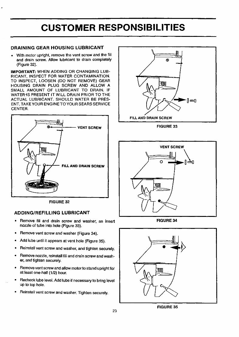
DRAINING GEAR HOUSING LUBRICANT
• With motor upright, remove the vent screw and the filland drain screw. Allow lubricant to drain completely(Figure 32).
IMPORTANT: WHEN ADDING OR CHANGING LUB-RICANT, INSPECT FOR WATER CONTAMINATION.TO INSPECT, LOOSEN (DO NOT REMOVE) GEARHOUSING DRAIN PLUG SCREW AND ALLOW ASMALL AMOUNT OF LUBRICANT TO DRAIN. IFWATER-IS PRESENT IT WILL DRAIN PRIOR TO THEACTUAL LUBRICANT. SHOULD WATER BE PRES-ENT, TAKE YOUR ENGINE TO YOUR SEARS SERVICECENTER.
VENT SCREW
FILL AND DRAIN SCREW
FIGURE 32
ADDING/REFILLING LUBRICANT
• Remove fill and drain screw and washer, an insertnozzle of tube into hole (Figure 33).
• Remove vent screw and washer (Figure 34).
• Add lube until it appears at vent hole (Figure 35).
• Reinstall vent screw and washer, and tighten securely.
• Remove nozzle, reinstall filland drain screw and wash-er, and tighten securely.
• Remove vent screw and allow motorto stand uprightforat least one-half (1/2) hour.
• Recheck lube level. Add lube if necessary to bring levelup to top hole.
• Reinstall vent screw and washer. Tighten securely.
_]==0
FILL AND DRAIN SCREW
FIGURE 33
VENT SCREW
FIGURE 34
FIGURE 3523

i i i
CUSTOMER RESPONSIBILITIES
SPECIAL SITUATIONS
SUBMERGED MOTOR FRESH WATER
• If motor is recovered within a few hours, and is not
damaged and does not have dirt inside, try to start asfollows:
• Drain fuel lines and carburetor.
• Remove spark plugs and turn motor over severaltimes by pulling starter rope to force water fromthe crankcase and cylinder.
• Dry off and install spark plugs and dry off ignitioncomponents.
• If fuel tank was submerged, drain all fuel from tankand flush with fresh fuel until all water is removed.
• Try starting motor, using fresh fuel mixture.
If motor starts, run for at least an hour until parts are
thoroughly warmed up and water has evaporated frommoving parts inside.
SUBMERGED MOTOR SALT WATER
IMPORTANT: DO NOT ATTEMPT TO START MOTORUNTIL ALL ELECTRICAL PARTS ARE CLEANED ANDDRIED.
• Immediately flush away all salt water, both inside andout, with clean fresh water.
• Follow all steps for fresh water submersion outlinedpreviously.
• If motor will not start, protect all electrical parts with
ignition dryer and conditioner and cover all externalparts with a thick coat of oil. "
• Immediately take motor to a Sears Service Center forservicing.
24

SERVICE AND ADJUSTMENTS
CARBURETOR
NOTE: Adjust the carburetor for better starting and lowspeed operation when there are changes in temperature,humidity or barometric pressure.
The high speed system, which meters fuel from high idleto wide open throttle, is factory equipped with a jet that isnot adjustable. The jet can be replaced with a jet for highaltitude operation. Consult your Sears Service Center forinstallation.
Adjust idle as outlined below:
INITIAL SETTING
NOTE: Do not overtightendamaged.
- needle and seat may be
BEFORE STARTING MOTOR:
• Remove motor cover.
• Tum idle adjustment needle in, clockwise, until it seatslightly (Figure 36).
• Back needle out one (1) full turn.
FINAL ADJUSTMENT
IMPORTANT:. DO NOT ADJUST LEANER THAN NECES-SARY TO OBTAIN sMooTH IDUNG. IT IS BETI'ER TOHAVE IDLE SET A U'rTLE RICH THAN TOO LEAN. A LEANsE-n'ING CAN CAUSE MOTOR DAMAGE.
With boat tied securely to dock, start motor and run untilfully warmed up.
Set controls to lowest reliable idle in neutral gear posi-tion.
Tum idle adjustment needle slowly open, counterclock-wise, until motor loses power and begins to roll due toan over-rich mixture. Note this position (Figure 37).
Slowly tum needle closed, clockwise, until motor runssmoothly and beginsto pick upspeed. Continue turningclockwise until motor pops or stalls due to lean mixture.Note this position.
Set needle halfway between the two positions.
Repeat, as needed for fine tuning.
THROTTLE STOP
• Your motor isequipped with a throttle stopwhich can beadjusted for correct idle speed.
o Ifneeded tum the throttlestop adjusting screw (A) to ob-tt_n approximately an 800 RPM idle when in neutralgear (Figure 38).
25
FIGURE 36
IDLE ADJUSTMENT SCREW
RICH LEAN HALFWAY
3 4 5
FIGURE 37
FIGURE 38

i i i i
STORAGE
PREPARATION FOR STORAGE
• We recommend that your Sears Service Center pre-
pare your motor for storage during the off season orfor long periods of time.
• The Service Center has the latest tools, materials andinformation and can also carry out maintenance asrequired.
• If your motor cannot be taken to your Sears ServiceCenter, follow the steps below to prevent rust anddamage from freezing temperatures.
IMPORTANT: IF GASOLINE MUST BE LEFT IN TANK,USE A GASOLINE STABILIZER. MIX STABILIZERACCORDING TO BOTTLE INSTRUCTIONS DURINGEACH TANK FILL UP TO ASSURE THAT IT WILL BEPRESENT DURING EACH STORAGE INTERVAL.
• Gasoline stabilizer helps prevent gum deposits fromforming in essential fuel system parts such as thecarburetor, fuel filter, fuel hose, or tank during stor-age. Also, experience indicates that alcohol blendedfuels (called gasohol or using ethanol methanol) canattract moisturewhich leads to separation and forma-tion of acids during storage. Acidic gas can damagethe fuel system of an engine while in storage.
• To avoid engine problems, the fuel system should beemptied before storage of 30 days or longer. Followthese instructions.
AVOID SPILLING FUEL AND KEEP ALL SOURCES OFHEAT, FLAME AND SPARKS AWAY WHEN DISCON-NECTING, HANDLING OR STORING FUEL SYSTEMCOMPONENTS.
• Remove motor cover.
With motor mountedon boat and infresh water, run themotor until it is thoroughly warmed up.
Place shift lever in neutral and run motor at fast idle(Figure 39).
O
Disconnect fuel line from bushing on motor (Figure 40).
When motor begins to stall, rapidly inject a rust preven-tative oil into the carburetor air intake for ten (10) totwenty (20) seconds until motor stops (Figure 41).
This protects the crankcase with a coating of oil.
• Remove boat and outboard from water.
II ©
FIGURE 39
FIGURE 40
)
FIGURE 41
26

STORAGE
• Remove spark plug and put an ounce or two of out-board oil into spark plug hole (Figure 42).
• Reinstall spark plug.
• Pull starter rope several times to lubricate piston, ringsand cylinder walls and to remove water from coolingsystem.
• Lubricate all parts, as outlined in Lubrication.
• Drain and refillgear housing, as outlined in Lubrication.
• Lubricate and service propeller, as outlined in Mainte-nance.
• Reinstall motor cover.
EXTERIOR CARE
• Your outboard isprotected with a durable enamel finish.To keep its appearance, wash and wax often using ma-rine cleaners and waxes (Figure 43).
PREPARATION FOR USE AFTER STORAGE
• We recommend that your Sears Service Center pre-pare your motor for use after storage. The ServiceCenter has the latest tools, materials and information.
• They can also perform maintenance as required bywarranty, test-run your motor and perform tune-upand adjustments needed for good operation. If yourmotor cannot be returned to your Sears Service Cen-ter, do the following steps:
• Remove spark plug and clean or replace, as out-lined under Maintenance.
• Lubricate all parts, as outlined under Lubrication.
• Check lubricant in gear housing, as outlined underLubrication.
• Service exterior of motor, as outlined under Exte-rior Care.
• Drain fuel tank and use a fresh fuel mixture.
FIGURE 42
FIGURE 43
27
i i
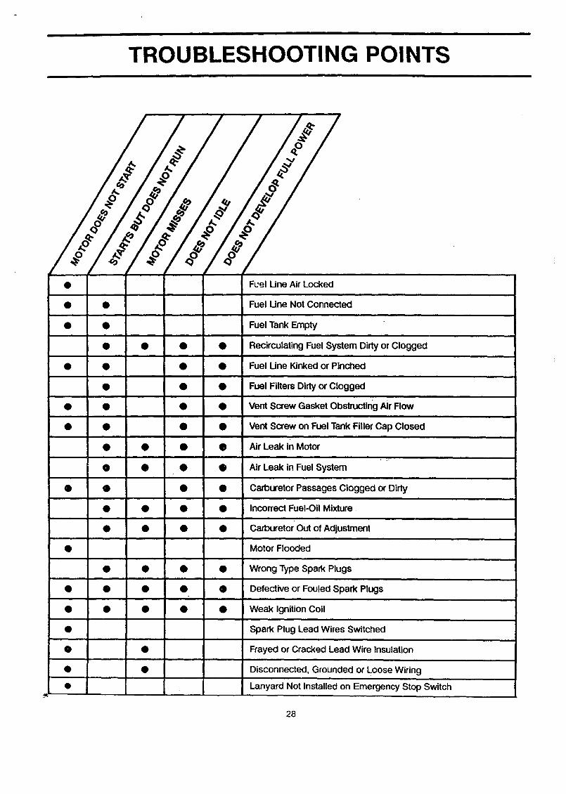
TROUBLESHOOTING POINTS
i
Q
i
• • •i
• • •i
• •
• • • •
FL'el Line Air Locked
Fuel Une Not Connectedi
Fuel Tank Empty
Recirculating Fuel System Dirty or Clogged
Fuel Line Kinked or Pinched
Fuel Filters Dirty or Cloggedi
Vent Screw Gasket Obstructing Air Flow
Vent Screw on Fuel Tank Filler Cap Closed
Air Leak in Motor
Air Leak in Fuel System
Carburetor Passages Clogged or Dirty
Incorrect Fuel-Oil Mixture.==
Carburetor Out of Adjustment
Motor Flooded
Wrong Type Spark Plugs
Defective or Fouled Spark Plugs
Weak Ignition Coil
Spark Plug Lead Wires Switched
Frayed or Cracked Lead Wire Insulation
Disconnected, Grounded or Loose Wiring
Lanyard Not Installed on Emergency Stop Switch
28

" INUI"_:
COWL ASSEMBLY - TOP AND BO-I-rOM .................................... 30IGNITION SYSTEM ....................................................... 32SHIFT LINKAGE .......................................................... 34FUEL AND RECIRCULATION SYSTEM ..................................... 36CARBURETOR ........................................................... 38STARTER ASSEMBLY .................................................... 40CRANKSHAFT AND PISTON ............................................... 42CYLINDER BLOCK ....................................................... 44STEERING HANDLE/TWIST GRIP THROTTLE ............................... 46SWIVEL BRACKET AND DRIVESHAFT HOUSING ........................... 48CLAMP BRACKETS ....................................................... 50THERMOSTAT ........................................................... 51GEAR HOUSING ......................................................... 52FUEL TANK AND LINE .................................................... 54MISCELLANEOUS PARTS ................................................. 55
OPT = optional AR = As Required N.S.S. = Not Sold Seperate
NOTE: indented description indicate that these parts are included in preceding
assembly.
THESE PARTS BOOKS/FICHE CARDS ARE COPYRIGHTED AND MAY NOT BE
DISTRIBUTED OR REPRODUCED IN ANY OTHER FORMAT.
29

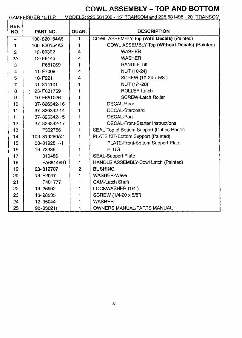
L;UWL/_:3_t:IVlI_LY - I UP AND BOTTOMGAMEFISHER 15 H.P. MODELS: 225.581508 - 15" TRANSOM and 225.581498 - 20" TRANSOM
PORT SiDE )
(STARBOARD SIDE
11
1920
\
23
13
12
25
30
GAMEFISHER 15 H.P.
COWL ASSEMBLY - TOP AND BOTTOMMODELS: 225.581508 - 15" TRANSOM and 225.581498 -20" TRANSOM
!
1
2
2A
3
4
5
7
8
9
10
11
11
12
13
14
15
16
17
18
19
20
21
22
23
24
25
PART NO.
100- 820i54A6
100- 820154A2
12- 89302
12- F8143
F681269
11- F7009
10- F2211
11-814101
23- F681759
10- F681026
37- 826342-16
37- 826342-14
37- 826342-15
37- 826342-17
F392756
100- 819280A2
38- 819281 --1
19- 73336
819486
FA681469T
23- 812707
13- F2047
F481777
13- 26992
10- 28635
12- 35044
90- 830211 I
QUAN.
1
1
4
4
1
4
4
1
1
1
1
1
1
1
1
1
1
1
1
1
2
1
1
1
1
1
1
DESCRIPTION
COWL ASSEMBLY-Top (Witl_ Decals) (Painted)
COWL ASSEMBLY-Top (Without Decals) (Painted)
WASHER
WASHER
HANDLE-Tilt
NUT (10-24)
SCREW (10-24 x 5/8")
NUT (1/4-20)
ROLLER-Latch
SCREW-Latch Roller
DECAL-Rear
DECAL-Starboard
DECAL-Port
DECAL-Front-Starter Instructions
SEAL-Top of Bottom Support (Cut as Req'd)
PLATE KIT-Bottom Support (Painted)
PLATE-Front-Bottom Support Plate
PLUG
SEAL-Support Plate
HANDLE ASSEMBLY-Cowl Latch (Painted)
BUSHING
WASHER-Wave
CAM-Latch Shaft
LOCKWASHER (1/4")
SCREW (1/4-20 x 5/8")
WASHER
OWNERS MANUAL]PARTS MANUAL
31
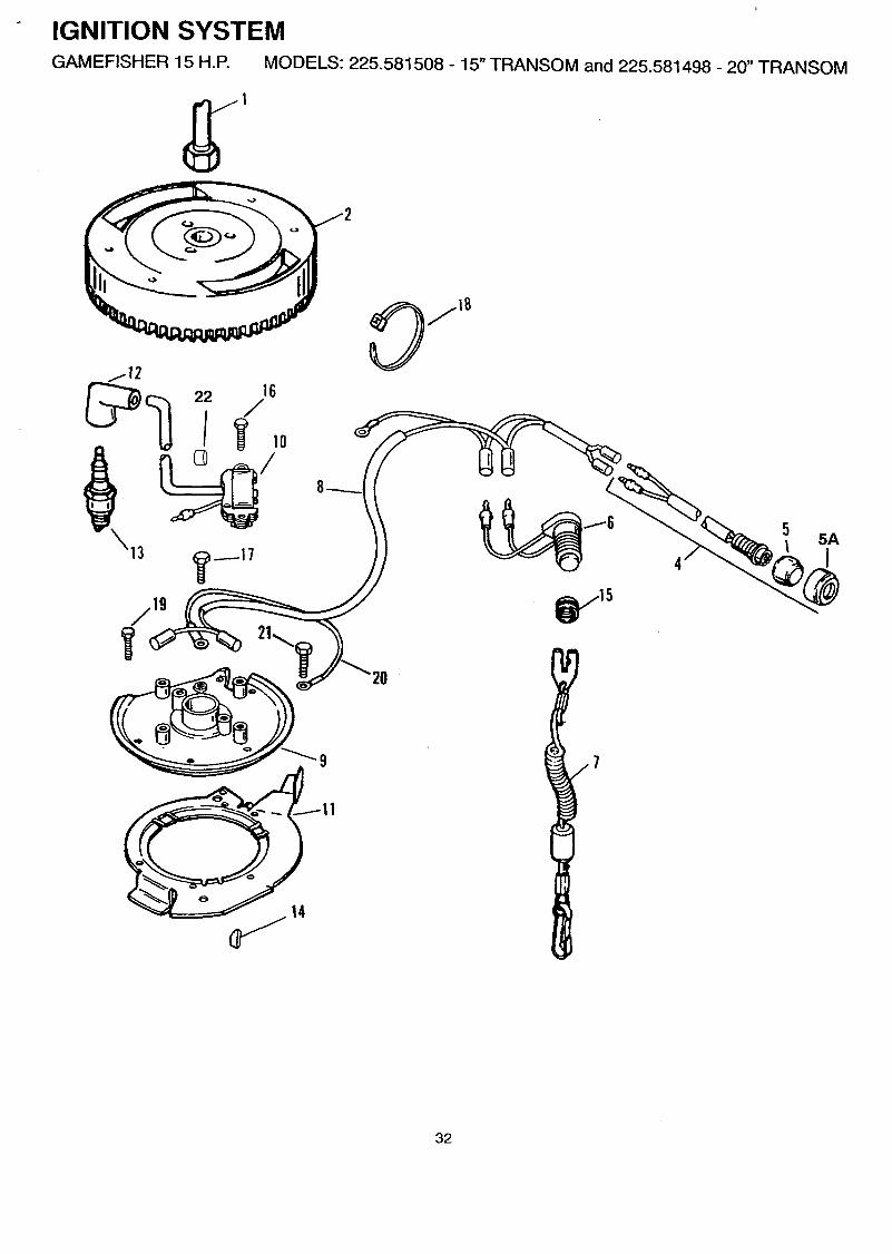
" IGNITION SYSTEMGAMEFISHER 15 H.P. MODELS: 225.581508 - 15" TRANSOM and 225.581498 -20" TRANSOM
22 16
8
It.
32

GAMEFISHER 15 H.P.
IGNITION SYSTEMMODELS: 225.581508 - 15" TRANSOM and 225.581498 - 20" TRANSOM
REENO.
1
2
4
5
5A
6
7
8
9
10
11
12
12
13
13
14
15
16
17
18
19
20
21
22
PART NO.
F681091
200- 824380T1
87- 824440A9
824466A3
824915
87- 826214A1
819399A1
84- 819379A7
300- 826692T
819156T
826691
FKl123
85- 818751
33- 328
33-814
28- F458498-1
22- F681188
10- 824353
10- 824352
56762
10- 824358
84- 60466A16
10- 824358
20117A1
54- 816311
QUAN.
1
1
1
1
1
1
1
1
1
2
1
2
OPT
2
OPT
1
1
6
1
1
5
1
1
1
2
DESCRIPTION
NUT-Flywheel
FLYWHEEL (Painted)
SWITCH ASSEMBLY-Stop
COVER ASSEMBLY-Stop Switch
BEZEL-Stop Switch Cover
SWITCH ASSEMBLY-Emergency Stop
LANYARD ASSEMBLY
HARNESS ASSEMBLY-Engine Stop
PLATE-Stator
MODULE-Ignition (Cut Wire as Req'd)
CAM-Throttle
BOOT KIT-Spark Plug
COVER-Spark Plug (RFI)
SPARK PLUG (CHAMPION # L82YC)
SPARK PLUG (RFI) (CHAMPION # RL82YC)
KEY-Crankshaft/Flywheel
NUT-Stop Switch Sleeve
SCREW (8-32 x 3/4")-Ignition Module
SCREW (10-24 x 3/8")-Ground
CABLE TIE (4")
SCREW (10-24 x 1/2")-Stator PlateWIRE ASSEMBLY-Ground
SCREW (10-24 x 1/2")-Ground
MARKER SET-Ignition Module Cable
CABLE TIE (8'_
33
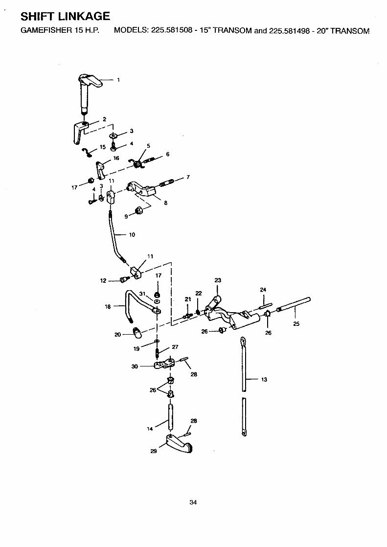
SHIFT LINKAGEGAMEFISHER 15 H.P. MODELS: 225.581508 - 15" TRANSOM and 225.581498 - 20" TRANSOM
5 6
17 I"__ 7
9.._.> 8
10
13
34

GAMEFISHER 15 H.E
REF.NO.
1
2
3
4
5
6
7
8
9
10
!1
!2
13
14
15
16
17
18
19
20
21
22
23
24
25
26
27
28
29
30
31
SHIFT LINKAGEMODELS: 225.581508 - 15" TRANSOM and 225.581498 - 20" TRANSOM
PART NO.
F681490
F681003-1
12- F8143
10- 48408
24- F681424
16- F681134
16- 826590
824357
11-814101
F681531-1
816514
10- 819625
F286615
824826
F681263-1
F681742
11-20110
825402
13- 26996
F286685
16- F98273
13- F8058
819508T
17- 31656
F286871
23- 26841
16- F286134
17- 25905
819626T
820367--1
13- F8048
QUAN.
1
1
1
1
1
1A
1A
1
1
1
2
1
1
1
1
1
2
1
1
1
1
1
1
1
1
4
1
2
1
1
1
DESCRIPTION
STOP-Starter Pulley Interlock
ARM-Starter Interlock
WASHER
SCREW (10-16 x 1/2")SPRING-Interlock Lever
STUD-Interlock Lever
STUD-(1/4-20 x 1.69") W/Dri Loc-Neutral Interlock Pivot
LEVER-Neutral Interlock
NUT (1/4-20)
ROD-Interlock
BEARING
SCREW-Shoulder
ROD-Gear Shift-Upper
SHAFT-Gear Shift Handle
LINK-Starter Interlock
LEVER-Intermediate Interlock
NUT (10-32)
LINK-Shift Lever
LOCKWASHER (#10)
CONNECTOR-Gear Shift Rod
STUD-Rod End Connector
LOCKWASHER (#10 Internal)
LEVER-Gear Shift (Painted)
PIN-Roll
PIN-Gear Shift Lever
BUSHING
STUD-Gear Shift Lever
PIN-Roll
HANDLE-Gear Shift (Painted)
LEVER-Shift Handle Shaft
WASHER-Bowed
• = Contents of Short Block Assy 800-819553A14
35

FUEL AND RECIRCULATION SYSTEMGAMEFISHER 15 H.P. MODELS: 225.581508 - 15" TRANSOM and 225.581498 - 20" TRANSOM
23
31 32
30
25
14
10
TO CARB_
TOP FITTING
20
34
6
24
,TO CARB;IDE ELBOW .i
16 i/<"
\
13
11
12
36
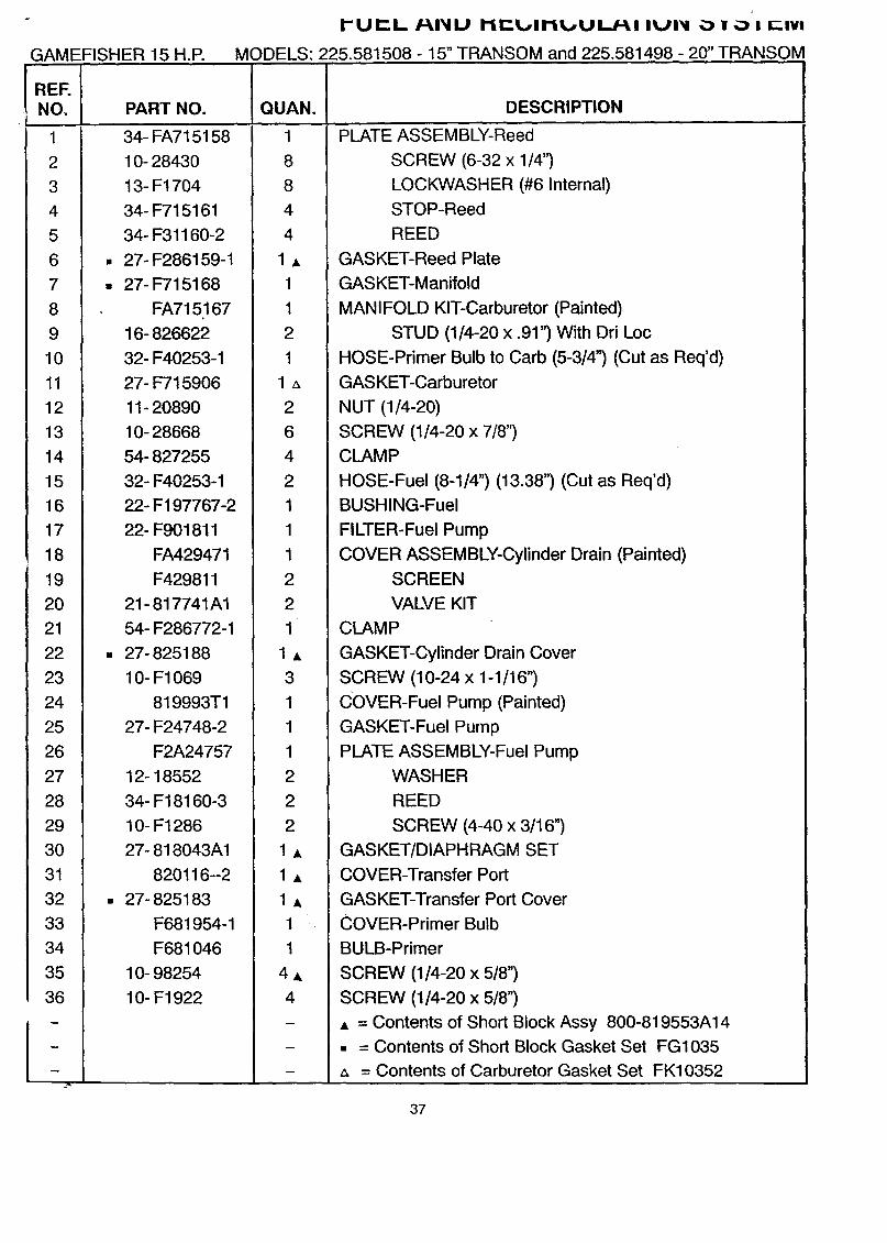
GAMEFISHER 15 H.P.
I"UIF_.L/-_I_IIU I1F-..LplII_,UL./-_I IUI_II _._ ; _,_ t _-tvt
MODELS: 225.581508 - 15" TRANSOM and 225.581498 - 20" TRANSOM
REF.NO.
1
2
3
4
5
6
7
8
9
10
11
12
13
14
15
16
17
18
19
20
21
22
23
24
25
26
27
28
29
3O
31
32
33
34
35
36
PART NO.
34- FA7i 5158
10- 28430
13- F1704
34- F715161
34- F31160-2
• 27- F286159-1
• 27- F715168
FA715167
16- 826622
32- F40253-1
27- F715906
11- 20890
10- 28668
54- 827255
32- F40253-1
22- F197767-2
22- F901811
FA429471
F429811
21- 817741A1
54- F286772-1
• 27- 825188
10- F1069
819993T1
27- F24748-2
F2A24757
12- 18552
34- F18160-3
10- F1286
27- 818043A1
820116--2
• 27-825183
F681954-1
F681046
10- 98254
10- F1922
QUAN.
1
8
8
4
4
1A
1
1
2
1
14
2
6
4
2
1
1
1
2
2
1
1A
3
1
1
1
2
2
2
1A
1A
1A
1
1
4A
4
DESCRIPTION
PLATE ASSEMBLY-Reed
SCREW (6-32 x 1/4")
LOCKWASHER (#6 Internal)
STOP-Reed
REED
GASKET-Reed Plate
GASKET-Manifold
MANIFOLD KIT-Carburetor (Painted)
STUD (1/4-20 x .91') With Dri Loc
HOSE-Primer Bulb to Carb (5-3/4') (Cut as Req'd)
GASKET-Carburetor
NUT (1/4-20)
SCREW (1/4-20 x 7/8")
CLAMP
HOSE-Fuel (8-1/4") (13.38") (Cut as Req'd)
BUSHING-Fuel
FILTER-Fuel Pump
COVER ASSEMBLY-Cylinder Drain (Painted)
SCREEN
VALVE KIT
CLAMP
GASKET-Cylinder Drain Cover
SCREW (10-24 x 1-1/16")
COVER-Fuel Pump (Painted)
GASKET-Fuel Pump
PLATE ASSEMBLY-Fuel Pump
WASHER
REED
SCREW (4-40 x 3/16")
GASKET/DIAPHRAGM SET
COVER-Transfer Port
GASKET-Transfer Port Cover
COVER-Primer Bulb
BULB-Primer
SCREW (1/4-20 x 5/8")
SCREW (1/4-20 x 5/8")
A = Contents of Short Block Assy 800-819553A14
• = Contents of Short Block Gasket Set FG1035
z_ = Contents of Carburetor Gasket Set FK10352
37

CARBURETORGAMEFISHER 15 H.P. MODELS: 225.581508 - 15" TRANSOM and 225.581498 - 20" TRANSOM
20
14
29
21
24
22
_5 31-o
I
34
3O
18
33
19
17
\2
13
10
38
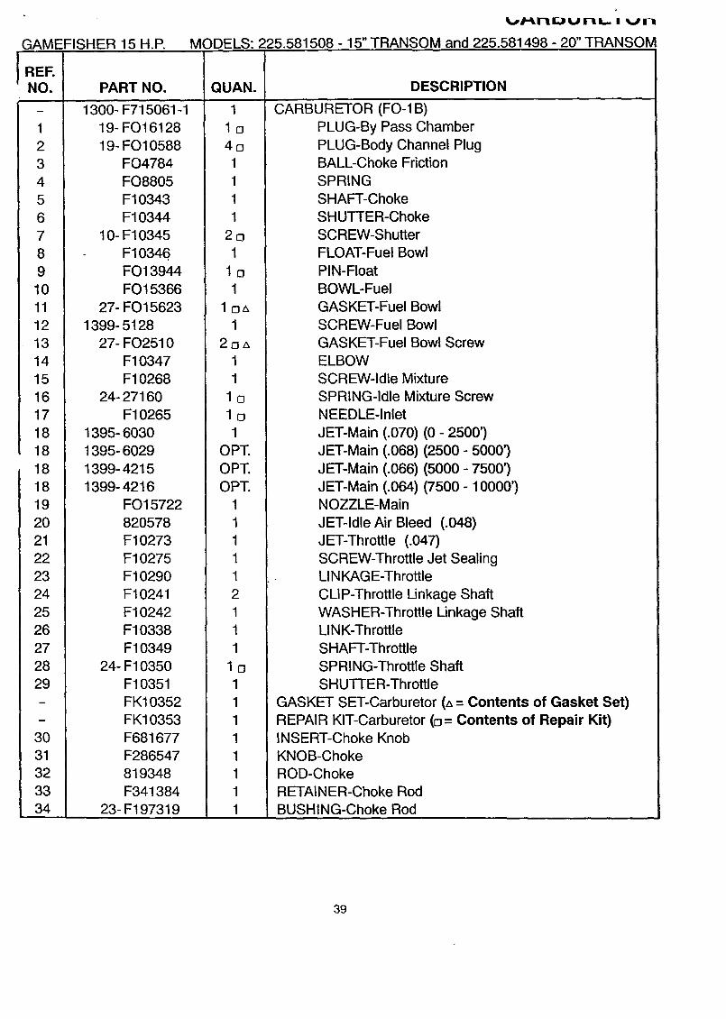
GAMEFISHER 15 H.P.
%J,I"_,FIII;_,,,I hi,.,,, ii _b,,,_rl
MODELS: 225.581508 - 15" TRANSOM and 225.581498 - 20" TRANSOM
REF.NO.
1
2
34
56
7
8
9
10
11
12
13
14
15
16
17
18
18
18
18
19
20
2122
23
24
25
26
27
28
29
30
3132
33
34
PART NO.
1300- F715061-1
19- FO16128
19- FO10588
FO4784
FO8805
F10343
F10344
10- F10345
F10346FO13944
FO15366
27- FO 15623
1399- 5128
27- FO2510
F10347
F10268
24- 27160
F10265
1395- 6030
1395- 6029
1399- 4215
1399- 4216
FO 15722
820578
F10273F10275
F10290F10241
F10242
F10338
F1034924- F10350
F10351
FK10352
FK10353
F681677
F286547
819348
F341384
23- F197319
QUAN.
1
lo
401
1
1
1
2o1
lo1
loz_1
2oz_
1
1
lo
lo1
OPT.
OPT.
OPT.
11
1
1
1
2
1
1
1
lo1
1
1
1
1
1
1
1
DESCRIPTION
CARBURETOR (FO-1B)
PLUG-By Pass Chamber
PLUG-Body Channel PlugBALL-Choke Friction
SPRING
SHAFT-Choke
SHUTTER-Choke
SCREW-Shutter
FLOAT-Fuel Bowl
PIN-Float
BOWL-Fuel
GASKET-Fuel Bowl
SCREW-Fuel Bowl
GASKET-Fuel Bowl Screw
ELBOW
SCREW-Idle Mixture
SPRING-Idle Mixture Screw
NEEDLE-Inlet
JET-Main (.070) (0- 2500')
JET-Main (.068) (2500- 5000')
JET-Main (.066) (5000- 7500')
JET-Main (.064) (7500- 10000')NOZZLE-Main
JET-Idle Air Bleed (.048)
JET-Throttle (.047)
SCREW-Throttle Jet SealingLINKAGE-Throttle
CLIP-Throttle Linkage Shaft
WASHER-Throttle Linkage ShaftLINK-Throttle
SHAFT-Throttle
SPRING-Throttle Shaft
SHUTTER-Throttle
GASKET SET-Carburetor (a = Contents of Gasket Set)
REPAIR KIT-Carburetor (o = Contents of Repair Kit)INSERT-Choke Knob
KNOB-Choke
ROD-Choke
RETAINER-Choke Rod
BUSHING-Choke Rod
39

STARTER ASSEMBLYGAMEFISHER 15 H.P. MODELS: 225.581508 - 15" TRANSOM and 225.581498 - 20" TRANSOM
13
23
16
i
i j
ii
J
/
K
21
t
//
13
40
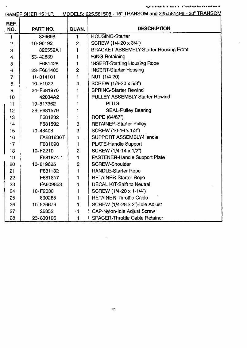
GAMEFISHER 15 H.P.
V IJr_l I i 51 | r-i_,.Pvi..iWmil,,,,p,,-,-- n
MODELS: 225.581508 - 15" TRANSOM and 225.581498 - 20" TRANSOM
REF.NO.
1
2
3
4
5
6
7
8
9
10
11
12
13
14
15
16
17
18
19
20
21
22
23
24
25
26
27
28
PART NO.
826693
10- 90192
826559A1
53- 42689
F681428
23- F681405
11-814101
10- F1922
24- F681970
42034A2
19- 817362
26- F681579
F681232
F681592
10- 48408
FA681630T
F681090
10- F2210
F681874-1
10- 819625
F681132
F681817
FA609853
10- F2030
830265
10- 826676
26852
23- 830196
QUAN.
1
2
1
1
1
2
1
4
1
1
1
1
1
3
3
1
1
2
1
2
1
1
1
1
1
1
1
1
DESCRIPTION
HOUSING-Starter
SCREW (1/4-20 x 3/4")
BRACKET ASSEMBLY-Starter Housing Front
RING-Retaining
INSERT-Starting Housing Rope
INSERT-Starter Housing
NUT (1/4-20)
SCREW (1/4-20 x 5/8")
SPRING-Starter Rewind
PULLEY ASSEMBLY-Starter Rewind
PLUG
SEAL-Pulley Bearing
ROPE (64/67")
RETAINER-Starter Pulley
SCREW (10-16 x 1/2")
SUPPORT ASSEMBLY-Handle
PLATE-Handle Support
SCREW (1/4-14 x 1/2'_
FASTENER-Handle Support Plate
SCREW-Shoulder
HANDLE-Starter Rope
RETAINER-Starter Rope
DECAL KIT-Shift to Neutral
SCREW (1/4-20 x 1-1/4")
RETAINER-Throttle Cable
SCREW (1/4-28 x 2")-Idle Adjust
CAP-Nylon-Idle Adjust Screw
SPACER-Throttle Cable Retainer
41

!JMAI_II_I'IAI" I AND PISTON
GAMEFISHER 15 H.P. MODELS: 225.581508 - 15" TRANSOM and 225.581498 - 20" TRANSOM
2O I
1"18
12
9
I
10
6
?
8
1110
42

GAMEFISHER 15 H.P.
_=rllI/'ll_ill\,,.,_l I/'ll-- I /'ll_iil./ I--I,_ I _IPl_il
MODELS: 225.581508 - 15" TRANSOM and 225.581498 - 20" TRANSOM
REENO.
1
2
3
5
6
7
8
9
11
12
13
14
15
16
17
18
19
20
PART NO.
10- 28636
1100- 817753A1
• 26-819801
• 27- F286277
400- 819803A2
30- F286028
29- F286571
FA286155
FA712228
600- FS715016
10- F175634
• 25-32509
31 - F343014
• 26-819396
700- 819946A3
53- F31410
41- F712017
39- 820484A1
QUAN.
4
1
1
1A
1A
1
1A
1A
2,
2,
4
1,
1,
1,
2,,
4
2
2
DESCRIPTION
SCREW (1/4-20 x 3/4")
CAGE ASSEMBLY-Crankshaft Bearing
SEAL-Crankshaft-Upper
GASKET-Crankshaft Bearing Cage
CRANKSHAFT ASSEMBLY
BEARING-Ball
ROLLER SET (26 Per Set)
LINER SET-Centermain Bearing
ROLLER SET (2 Strips-28 Per)CONNECTING ROD ASSEMBLY
SCREW-Corm Rod
O RING
BEARING-Crankshaft Lower Main
SEAL-Crankshaft Lower
PISTON KIT
RING-RetainingPIN-Piston
RING SET-Piston (2 Rings)
, = Contents of Short Block Assy 800-819553A14
• = Contents of Short Block Gasket Set FG1035
3

CYLINDER BLOCKGAMEFISHER 15 H.P. MODELS: 225.581508 - 15" TRANSOM and 225.581498 - 20" TRANSOM
14
13
J
1
7
44

GAMEFISHER 15 H.P. MODELS: 225.581508 - 15" TRANSOM and 225.581498 - 20" TRANSOM
REF.NO.
1
2
3
4
5
6
7
8
9
10
11
12
13
14
15
16
17
18
19
PART NO.
800- 819553A14
800- 819553A12
10- Fl107
10- F1335
17- F8559
FG 1O35
824141T
10- 28668
-. 27- F715154
F715151
• 27- F715279-1
10- 35386
• 27- F286529-3
900- F286518T
10- F901938-1
12- 37998
32- F715943
10- 28636
13- 26992
F715660
QUAN.
1
1A
8
4
2
1
1A
12
2A
1A
1A
6
1A
1
8
8
1
3
3
1
DESCRIPTION
SHORT BLOCK ASSEMBLY (Painted)
CYLINDER KIT
• SCREW (1/4-20 x 3/4")
SCREW (5/16-18 x 1-1/4")PIN-Dowel
GASKET SET
COVER-Exhaust (Painted)
SCREW (1/4-20 x 7/8")
GASKET-Exhaust Port Cover
PLATE-Exhaust
GASKET-Cylinder Mounting
SCREW (5/16-18 x 1")
GASKET-Cylinder Head
HEAD-Cylinder (Painted)
SCREW-Cylinder Head
WASHER
TUBE-Cylinder Water Jacket
SCREW (1/4-20 x 3/4'_
LOCKWASHER (1/4")
TUBE-Exhaust
• - Contents of Short Block Assy 800-819553A14• = Contents of Short Block Gasket Set FG1035
45

STEERING HANDLE/TWIST GRIP THROTTLEGAMEFISHER 15 H.P. MODELS: 225.581508 - 15" TRANSOM and 225.581498 - 20" TRANSOM
19
20 19
13
24 \
26
14
16
46

GAMEFISHER 15 H.P.
I ILLr'I't n/-_m,_ULr- l-_l_lU I I'IHU I ! L_ LINI_(_P_.
MODELS: 225.581508 - 15" TRANSOM and 225.581498- 20" TRANSOM
RERNO.
1
2
3
4
5
6
7
8
9
10
11
12
13
14
15
16
17
18
19
20
21
22
23
24
25
26
27
28
29
30
31
32
PART NO.
817751T1
17- F1807
10- 823595
10- 823594
24- F286868
23- 26856
F286490
819914A2
10- 828815
19- F286539
11-814101
10- 28635
826592
87- 824440A9
824466A3
824915
10- 826575
827252
826609T
12- F286220
23- 26856
F286224-
23- 812707
25- 21836
F702178
25- 23145
F702137
828406
37- F712894
10- 824352
826591'
816514
13- 78968
QUAN.
1
1
1
1
1
2
1
1
1
1
1
2
1
1
1
1
3
1
1
2
2
1
1
1
1
1
1
1
1
1
1
1
2
DESCRIPTION
BRACKET-Steering (Painted)PIN-Groove
SCREW-Steering Handle Pivot
SCREW-Steering Handle Pivot
SPRING-Steering Handle Stop
BUSHING
STOP-Steering Handle
ARM/KINGPIN ASSEMBLY-Steering (Painted)
SCREW (1/4-20 x 1-3/4")
BUMPER
NUT (1/4-20)
SCREW (1/4-20 x 5/8")CABLE ASSEMBLY-Throttle
SWITCH ASSEMBLY-Stop
COVER ASSEMBLY-Stop Switch
BEZEL-Stop Switch Cover
SCREW (8-32 x 5/8")
ARM-Steering (LOWER)
HANDLE-Steering (Painted)
WASHER
BUSHING
INSERT-Steering Handle PivotBUSHING
O RING (LARGE)
RETAINER-Grip
O RING (SMALL)
GRIP-Steering Handle
SLEEVE-Steering Handle Grip
DECAL-Speed Indicator
SCREW (10-24 x 3/8")
BUSHING
BEARING-Connector
LOCKWASHER (1/4" Internal)
47

SWIVEL BRACKET AND DRIVESHAFT HOUSINGGAMEFISHER 15 H.P. MODELS: 225.581508 - 15" TRANSOM and 225.581498 - 20" TRANSOM
18
24
21
4
See Page 46/47Ref. No. 8
48

_,,,.} VV I V 1__1.-- I.,,/I i/"lVl\l.- i /"_itliJ I,..,P! I! V I,.._.,./I It'll I i 1%.,/_../,_,.,711'I1'%,_i
GAMEFISHER 15 H.P. MODELS: 225.581508 - 15" TRANSOM and 225.581498 - 20" TRANSOM
REF.NO.
1
2
3
4
5
5A
6
7
8
9
10
11
12
13
14
15
16
17
18
19
20
21
22
24
25
26
27
28
30
31
32
3334
35
36
37
38
39
4O
41
43
44
PART NO.
F7154O4
10- F2417
1400- 817750A4
22- F213274
23- F286169
23- F681169
17- 819707
F681631
54- F286573-1-,
10- F1820
12-12038
11- F1608
F286364
17- F8538
23- 26856
17- F1794
23- F536813
FA387742
12- F2037
F286827
12- F286286-1
17- F1806
12- F286011
37- F688585
FA341510
F286433
F286349
24- F286300
819320T
FA1844
13- 26992
11- 64015FA492845T
10- F430732
32- FS901244
F286346
1500- 819344T
32- F286244
F286914-1
26- F901307-2
F286347
37- 818029
QUAN.
1
2
1
2
1
1
1
1
1
1
1
1
1
1
1
2
1
1
1
1
1
1
1
1
1
1
1
1
2
2
2
21
4
1
1
1
1
1
1
2
1
DESCRIPTION
PLATE-Leg Tuner
SCREW (1/4-20 x 3/8")
BRACKET KIT-Swivel (Painted)FITTING-Grease
BUSHING-Bottom (1-3/4")
BUSHING-Top (1-1/8")PIN-Tilt Lock
SHOE-Friction-Swivel Bracket
CLAMP-Steering Friction
SCREW (1/4-20 x 1-3/8")WASHER
NUT (1/4-20)LEVER-Reverse Lock
PIN-SpringBUSHING
PIN-SpringBUSHING
LEVER ASSEMBLY-Intermediate
WASHER
LEVER-Reverse Lock
WASHER
PIN-Groove
WASHER-Swivel Bracket
DECAL-Tilt Lock
LINK-Reverse Lock
BRACKET-Shallow Water Drive
LOCK-Reverse
SPRING-Reverse Lock
BRACKET-Shock Mount Lower (Painted)
SCREW KIT (1/4-20 x 2-3/8")
LOCKWASHER (1/4")
NUT (1/4-20)
EXTENSION KIT (Painted)
SCREW (5/16-18 x 1-1/4')LINE-Water-Extension
MOUNT-Shock-Lower
HOUSING-Driveshaft (Painted)
LI N E-Water
SLEEVE-Water Line
SEAL-Driveshaft
MOUNT-Shock-UpperDECAL-Fuel Mix
20"-For Model
225.581498
49
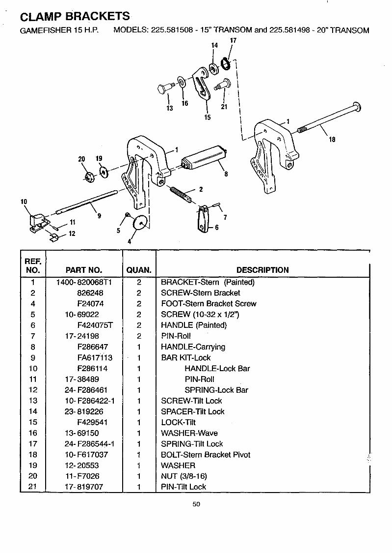
CLAMP BRACKETSGAMEFISHER 15 H.P. MODELS: 225.581508 - 15" TRANSOM and 225.581498 - 20" TRANSOM
1714
10
11
12
20 19
III
1613 21
15III
18
REF.NO.
1
2
4
5
6
7
8
9
10
11
12
13
14
15
16
17
18
19
20
21
PART NO.
1400- 820068T1
826248
F24074
10- 69022
F424075T
17- 24198
F286647
FA617ii3
F286114
17- 38489
24- F286461
10- F286422-1
23- 819226
F429541
13- 69150
24- F286544. -t
10- F617037
12- 20553
11- F7026
17- 819707
QUAN.
2
2
2
2
2
2
1
1
1
1
1
1
1
1
1
1
1
1
1
1
DESCRIPTION
BRACKET-Stem (Painted)SCREW-Stern Bracket
FOOT-Stern Bracket Screw
SCREW (10-32 x 1/2")
HANDLE (Painted)PIN-Roll
HANDLE-Carrying
BAR KIT-Lock
HANDLE-Lock Bar
PIN-Roll
SPRING-Lock Bar
SCREW-Tilt Lock
SPACER-Tilt Lock
LOCK-Tilt
WASHER-Wave
SPRING-Tilt Lock
BOLT-Stern Bracket Pivot
WASHER
NUT (3/8-16)
PIN-Tilt Lock
50
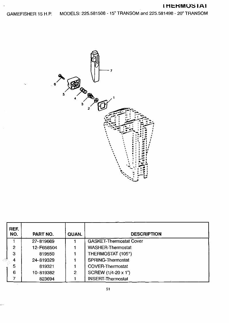
GAMEFISHER 15 H.P.
I I-II'-I-IMU_ IAI
MODELS: 225.581508 - 15" TRANSOM and 225.581498 - 20" TRANSOM
.6
! _7
54
3
REF.NO.
1
2
3
4
5
6
7
PART NO.
27- 819669
12- F658504
819550
24- 819329
819321
10- 819382
823694
QUAN.
1
1
1
1
1
2
1
DESCRIPTION
GASKET-Thermostat Cover
WASHER-Thermostat
THERMOSTAT (105 ° )
SPRING-Thermostat
COVER-Thermostat
SCREW (1/4-20 x 1")
INSERT-Thermostat
51

GEAR HOUSINGGAMEFISHER 15 H.P. MODELS: 225.581508 - 15" TRANSOM and 225.581498 - 20" TRANSOM
35--
33
52

GAMEFISHER 15 H.P.
I_I::AH I-IUU:51N_
MODELS: 225.581508 - 15" TRANSOM and 225.581498 - 20" TRANSOM
REF.NO. PART NO.
D
1234567891011121314151617181920212223242526272829304
313233343536373738394O414243444445464748495051.£9
1600- 819483A21600- 817749A2
10- F5010912- 1918317- 4845043- 819251A130- F127910-224- F286895
F28672113- 2699211- 2089012- F28690331 - 4891343- 819252A112- F45671717- F28672852- 81925317- F856424- F40971944- F45609843- 819254A131 - 817756A225- F45530526- 6602210- 28639
1500- 824916A110- F5010912-1918316- 82654226- 81747226- F901307-217- 48450
FP715FA324101
11- 817752A118- 45882
F28661510- F1976
F286705-1819962
10- F 180012- 3799810- F43073227- F28655510- F2030
F34156245- F34312845- F34412817- F90156347- F436065-246- FA71506026- F901307-2
F715388FA510914FK1065FKIN.ql-1
QUAN.
111
111111111121111111
211
1
lJ111111111114
4.1.11
1.1.1.
1111
DESCRIPTION
HOUSING KIT-Gear (COMPLETE) (Painted)HOUSING KIT-Gear (BASIC) (Painted)
PLUGWASHERPIN-Dowel
GEAR ASSEMBLY-PinionBEARING-Ball
SPRING-Shift CamCAM-ShiftLOCKWASHER (1/4")NUT (1/4-20)WASHERBEARING-PropshaftGEAR ASSEMBLY-ForwardWASHER-ThrustPIN-ShiftCLUTCHPIN-SpiralSPRING-ClutchPROPSHAFTGEAR ASSEMBLY-ReverseCAGE ASSEMBLY-Propshaft (Painted)
SEALSEAL
SCREW (1/4-20 x 5/8")HOUSING KIT-Driveshaft-Upper (Painted)
PLUGWASHERSTUD (1/4-20 x 1.36")SEAL-Gear Shift RodSEAL-DriveshaftPIN-Dowel
PROPELLER (8-3/8 x 6 x 3)PIN KIT-Propeller (3 Pins with Cotter Pin)NUT KIT-Propeller
PIN-CotterROD-Gear Shift-UpperSCREW (10-24 x 1/2") ,ROD-Gear Shift-Lower-15'-For Model 225.581508ROD-Gear Shift-Lower-20"-For Model 225.581498BOLT (1/4-20 x 7")WASHERSCREW (5/16-18 x 1-1/4")GASKET-Gear HousingSCREW (1/4-20 x 1-1/4")PLATE-Water PumpDRIVESHAFT-15' -For Model 225.58i508DRIVESHAFT-20"-For Model 225.581498PIN-DriveIMPELLERBODY ASSEMBLY-Water Pump
SEAL-DriveshaftDISCSEAL-Water Line
SEAL KIT-Gear Housing (D= Contents of Seal Kit)IqI=PAIR KIT-W_tp.r Pl Imn f-.-_ _nnte_nt_q ¢_f R__n_ir Kit_
53

FUEL TANK AND LINEGAMEFISHER 15 H.P. MODELS: 225.581508 - 15" TRANSOM and 225.581498 - 20" TRANSOM
3_
1412 13 |
IIII
Jt/
118
10
15
II
_-.-2
54

GAMEFISHER 15 H.P.
I-UEL TANK AND LINEMODELS: 225.581508 - 15" TRANSOM and 225.581498 - 20" TRANSOM
REE
:NO.
D
1
2
3
4
5
6
7
8
9
10
11
12
13
14
15
16
PART NO.
1259- 823504A3
1259- 823504A1
823536
22- 823532
25- 823533
35- 823534
32- 820572A8
13330A3
21- 13331A121-13331_?.
54- 41582-10
54- 41582--7
F197787-3
F17815
F17816
22- 89771 --1
54- 41582--7
32-16789-78
32- 16789100
QUAN.
1
1
1
1
1
1
1
1
1
1
2
2
1
1
1
1
2
AR
AR
DESCRIPTION
TANK ASSEMBLY-Fuel (COMPLETE)TANK ASSEMBLY-Fuel
GAUGE & CAP ASSEMBLY
CONNECTOR ASSEMBLY-Fuel
O RING
SCREEN-Filter
LINE ASSEMBLY-Fuel (5/16" I.D.) (30" & 60")BULB ASSEMBLY-Primer
VALVE-Check (INLET)
VALVE-Check (OUTLET)
CLAMP (LARGE)
CLAMP (SMALL)
CONNECTOR-Fuel-Engine
SEAL (SMALL)
SEAL (LARGE)CONNECTOR-Fuel Tank
CLAMP (SMALL)
LINE-Fuel (9') Cut as Req'd
LINE-Fuel (100') Cut as Req'd
GAMEFISHER 15 H.P.
REF.NO. PART NO.
- 92- 818252-12
- 92- 825321-12
- 92- 819107-12
MISCELLANEOUS PARTSMODELS: 225.581508 - 15" TRANSOM and 225.581498- 20" TRANSOM
QUAN.
AR
AR
AR
DESCRIPTION
LACQUER-Graphite Gray Acrylic-Spray Can (12 Per Case)
LACQUER-Graphite Gray Acrylic-Brush Bottle (12 Per Box)
LACQUER-Clear Acrylic-Spray Can (12 Per Case)
55

SEARS
OWNER'SMANUAL
MODEL NO.225.581508
15" TRANSOM
225.581498
20" TRANSOM
IF YOU NEEDREPAIR SERVICE
OR PARTS:
FOR REPAIR SERVICE, CALL
THIS TOLL FREE NUMBER;
1-800-4-REPAIR(1-800-473-7247)
FOR REPLACEMENT PARTSINFORMATION AND
ORDERING, CALL THISTOLL FREE NUMBER
1- 800-FON-PART(1-800-366-7278)
GAMEFISHER 15 HORSEPOWEROUTBOARD MOTOR
Each Outboard Motor has its own model and serial
number.
The model and serial number of your outboard motor willbe found on a decal attached to the port stern bracket.
All parts listed herein may be ordered through Sears,Roebuck and Co. Service Centers and most Retail
Stores.
WHEN ORDERING REPAIR PARTS, ALWAYS GIVE THEFOLLOWING INFORMATION:
• PRODUCT-OUTBOARD MOTOR
• MODEL NUMBER - 225.581508 (15"TRANSOM)225.581498 (20"TRANSOM)
• SERIAL NUMBER-
• PART NUMBER-
• PART DESCRIPTION -
Your Sears merchandise has added value when you con-sider that Sears has service units nationwide staffed with
Sears trained technicians...professional techniciansspecifically trained on Sears products, having the parts,tools and the equipment to insure that we meet our
pledge to you, we service what we sell.
Sears Roebuck and CO., Hoffman Estates, IL. 60179 U.S.A.
Printed in U.S.A. 90-830211 1-395