galaxy s6 edge + glass/lcd repair guide - zendesk · pdf filesamsung galaxy s6 edge +...
TRANSCRIPT

Galaxy S6 edge + Glass/Lcd REPAIR GUIDE
Version 1
2016 Edition

RiAna Soto Repair Training Specialist
Samsung Galaxy S6 edge + Glass/LCd REPAIR GUIDE

FOR EVERY REPAIR
MAKE SURE TO COMPLETE, INITIAL,
AND HAVE CUSTOMER SIGN THE CELLAIRIS
REPAIR LIABILITY WAIVER FORM

PRE-REPAIR DEVICE CHECK-IN

• Philips screwdriver
• Spudger
• Tweezers
• Isesamo
• Pentalobe screwdriver
•Magnetic Mat
• Samsung Galaxy s6 edge plus
digitizer/Lcd
TOOLS NEEDED

• Always operate the heat gun on the lowest setting.
• Keep face, hands, hair, and clothing away from the air stream.
• The air nozzle also becomes extremely hot. Never grab the heat gun by the nozzle.
• Never operate the heat gun by laying it on its side on a table. It should be firmly grasped in one hand
at all times during usage.
• Never operate near flammable or explosive liquids and vapors. Cleaning supplies and the 3M #94
Primer are of concern. Make sure fumes are absent from the work area before operating the heat gun
• The heat gun nozzle should never get closer than 2“ to the object being heated.
• Keep heat gun moving. Never stay in one spot.
HEAT-GUN PRECAUTIONS

• Magnetic Pad: During the repair, you will be utilizing a magnetic pad to organize the plethora of
differing screws that you will be pulling out of the iPhone 6S. Below is a list of several internal
components of the iPhone 6S that should never be placed on the pad, or you risk damaging the
hardware or erasing client data:
• LCD/Digitizer Assembly
• Cameras
• Motherboard
• Battery
• Speaker
ADDITIONAL PRECAUTIONS

• Power on/off: To avoid any damage to the hardware during the repair, it is best to have the device
powered off until you can get to and disconnect the battery.
• Battery: Never unplug any flex cables unless the battery has been completely disconnected to avoid
frying your hardware. Do not plug the battery back until all cables have been reconnected.
• Release Screws: Apply pressure on the screw and twist counterclockwise to initially loosen it, then
lighten the pressure and continue twisting until the screw is gently released. Make sure you have
properly sized screwdrivers available for the repair.
• Pin Connectors: extremely fragile and must be plugged or unplugged with extreme caution.
• Battery connector: held down by light adhesive and solder. If not cautious it will come off the
motherboard. Very time consuming to be repaired. Do not break it in the first place.
• Motherboard: small surface mount components can be easily damaged if they are nicked by the
spudger. Always take your time and never touch the surface of the motherboard.
ADDITIONAL PRECAUTIONS

STEP 1
• Power off device.
• Remove sim card.
Disassemble the device
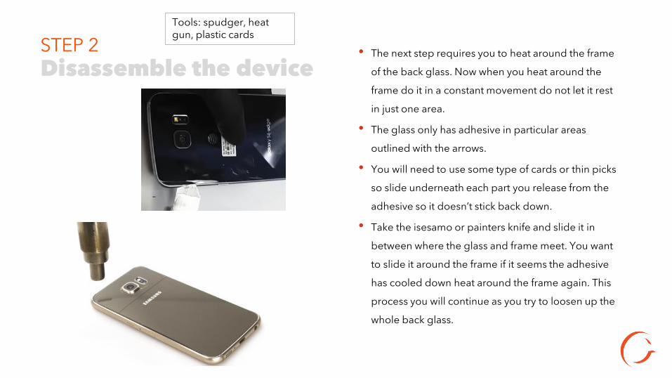
STEP 2 • The next step requires you to heat around the frame
of the back glass. Now when you heat around the
frame do it in a constant movement do not let it rest
in just one area.
• The glass only has adhesive in particular areas
outlined with the arrows.
• You will need to use some type of cards or thin picks
so slide underneath each part you release from the
adhesive so it doesn’t stick back down.
• Take the isesamo or painters knife and slide it in
between where the glass and frame meet. You want
to slide it around the frame if it seems the adhesive
has cooled down heat around the frame again. This
process you will continue as you try to loosen up the
whole back glass.
Disassemble the device
Tools: spudger, heat gun, plastic cards

STEP 3
Disassemble the device
Tools: plastic cards, isesamo or painters knife
• As you heat up and loosen the areas around the frame put
plastic picks or plastic cards underneath.
• Do not push the isesamo or painters knife to far into the
back as you slide this tool only the tip. The adhesive does
not have a thick lining but, you can possibly Knick
something.

STEP 4
• Now that the back glass is
removed.
• Unscrew the 18 Philips screws.
• Peel back black tape to
expose the battery ( area
pointed out with Red arrows)
Disassemble the device
Tools: Spudger, fingers

STEP 5
• Next step requires you to heat the front of the screen for 4 to 6 seconds in a constant motion at a 45 degree angle. Then begin pushing the on the battery forward to help separate the frame from the Digitizer/LCD.
• If you notice difficulty you can use the tip of isesamo or painters knife to go around the glass in between the frame of the phone.
Disassemble the device
Tools: spudger, heat gun

STEP 6
• Once you have gone all the way around the screen
separating the screen from housing you should be able to
push it through the frame.
• Peeling black tape up slightly covering the battery can help
push the frame out around the glass and Lcd exposing the
motherboard.
Disassemble the device
Tools: spudger, tweezers

STEP 7
• The back housing should be off at this point so we will start by unplugging the battery.
• Next, disconnect the Bluetooth and Wi-Fi antenna cables using the flat end of spudger.
• Disconnect home button connector by using flat end of spudger.
• Disconnect front camera.
Disassemble the device
Tools: Philips screwdriver, spudger
Battery
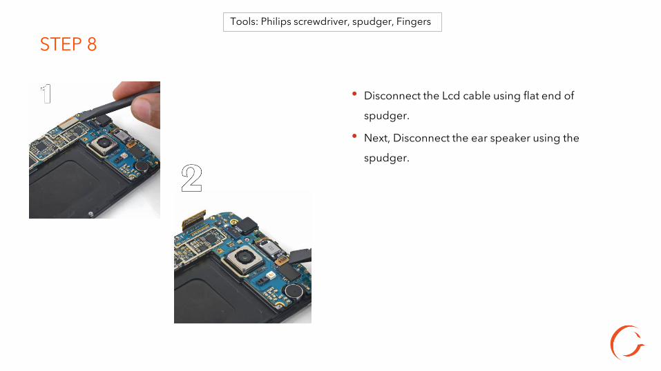
STEP 8
• Disconnect the Lcd cable using flat end of
spudger.
• Next, Disconnect the ear speaker using the
spudger.
Tools: Philips screwdriver, spudger, Fingers

STEP 9
• After, those components are disconnected lift up the motherboard at the top near camera side.
• There is one cable attached underneath the motherboard disconnect that ribbon cable using flat end of
spudger.
Tools: Philips screwdriver, spudger, Fingers

STEP 10
• Now that the motherboard is out we can separate the glass/lcd from the back housing.
• Use the isesamo, plastic card, or painters knife and slide it in between the plastic frame and glass.
• Once it is in place slide it down and all the way around frame.
Tools: Philips screwdriver, spudger, Fingers

STEP 11
• Once the back housing is loosened go ahead and pull it up.
• The plastic housing should just slide off.
• Make sure the bottom flex cable buttons are still attached to frame not original glass. Using heat to help separate the adhesive holding those down can help prevent ripping the cables.
Tools: heat gun, spudger, Fingers
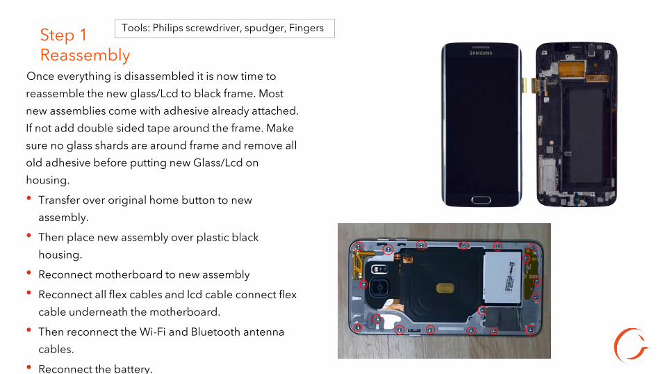
Step 1 Reassembly
Once everything is disassembled it is now time to reassemble the new glass/Lcd to black frame. Most new assemblies come with adhesive already attached. If not add double sided tape around the frame. Make sure no glass shards are around frame and remove all old adhesive before putting new Glass/Lcd on housing.
• Transfer over original home button to new assembly.
• Then place new assembly over plastic black housing.
• Reconnect motherboard to new assembly
• Reconnect all flex cables and lcd cable connect flex cable underneath the motherboard.
• Then reconnect the Wi-Fi and Bluetooth antenna cables.
• Reconnect the battery.
• Once that is connected put the plastic housing back on and screw in the Philips screws.
Tools: Philips screwdriver, spudger, Fingers

STEP 2
• Next, put the back glass back on now if it’s the original glass you might need to add a thin layer of adhesive around the frame of the back glass. Outlined with the white shade of tape around the frame. If it’s a replacement back glass and doesn’t come with adhesive on it definitely add some around the frame. Then apply back glass to phone. Smooth around the back with your hands to help seal.
• Power on device and do post test.
Tools: Philips screwdriver, spudger, Fingers
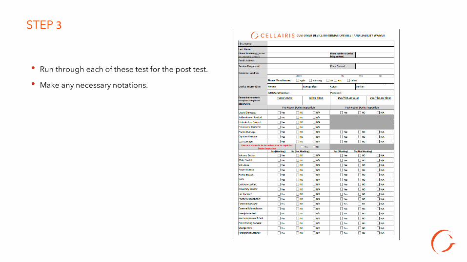
• Run through each of these test for the post test.
• Make any necessary notations.
STEP 3
STEP 4
Troubleshooting • After the repair is done make sure the touch is responsive. If you notice that the touch is delayed could mean the part is defective. Try a new one. • Also check part Lcd connector could mean not properly aligned.
